

Ingersoll-Rand EP 20 SE, HXP 25 SE, HP 20 SE, HXP 20 SE, EP 25 SE Operators/instruction Manual Options
...
Before installation or starting the compressor for the
APDD 567A
®
first time, this manual should be studied carefully to
obtain a clear knowledge of the unit and of the duties
to be performed while operating and maintaining the
unit.
RETAIN THIS MANUAL WITH UNIT.
This Technical manual contains IMPORTANT SAFETY
DATA and should be kept with the air compressor at all
times.
EP/HP/HXP 20 SE
EP/HP/HXP 25 SE
OPERATORS/
INSTRUCTION MANUAL
OPTIONS
September 1998

BONDED WARRANTY & REGISTERED START UP
AIR COMPRESSOR GROUP
Warranty
The Company warrants that the equipment manufactured by it and delivered hereunder will be free of defects in material
and workmanship for a period of twelve months (see extended airend warranty) from the date of placing the Equipment
in operation or eighteen months (see extended airend warranty) from the date of shipment from Davidson, NC, whichever
shall first occur. The Purchaser shall be obligated to promptly report any failure to conform to this warranty, in writing to
the Company in said period, whereupon the Company shall, at its option, correct such nonconformity, by suitable repair
to such equipment or, furnish a replacement part F.O.B. point of shipment, provided the Purchaser has stored, installed
maintained and operated such Equipment in accordance with good industry practices and has complied with specific
recommendations of the Company. Accessories or equipment furnished by the Company, but manufactured by others,
shall carry whatever warranty the manufacturers have conveyed to the Company and which can be passed on to the
Purchaser. The Company shall not be liable for any repairs, replacements, or adjustments to the Equipment or any costs
of labor performed by the Purchaser or others without Company’s prior written approval.
The effects of corrosion, erosion and normal wear and tear are specifically excluded. Performance warranties are limited
to those specifically stated within the Company’s proposal. Unless responsibility for meeting such performance
warranties are limited to specified tests, the Company’s obligation shall be to correct in the manner and for the period of
time provided above.
THE COMPANY MAKES NO OTHER WARRANTY OR REPRESENTATION OF ANY KIND WHATSOEVER,
EXPRESSED OR IMPLIED, EXCEPT THAT OF TITLE, AND ALL IMPLIED WARRANTIES OF MERCHANTABILITY
AND FITNESS FOR A PARTICULAR PURPOSE, ARE HEREBY DISCLAIMED.
Correction by the Company of nonconformities whether patent or latent, in the manner and for the period of time
provided above, shall constitute fulfillment of all liabilities of the Company for such nonconformities whether based on
contract, warranty negligence, indemnity, strict liability or otherwise with respect to or arising out of such Equipment.
The purchaser shall not operate Equipment which is considered to be defective, without first notifying the Company in
writing of its intention to do so. Any such Equipment will be at Purchaser’s sole risk and liability.
Limitation or Liability
The remedies of the Purchaser set forth herein are exclusive, and the total liability of the Company with respect to this
contract or the Equipment and services furnished hereunder, in connection with the performance or breach thereof, or
from the manufacture, sale, delivery, installation, repair or technical direction covered by or furnished under this contract,
whether passed on contract, warranty negligence, indemnity, strict liability or otherwise, shall not exceed the purchase
price of the unit of Equipment upon which such liability is based.
The Company and its suppliers shall in no event be liable to the Purchaser, any successors in interest or any beneficiary
or assignee of this contract for any consequential, incidental, indirect, special or punitive damages arising out of this
contract or any breach thereof, or any defect in, or failure of, or malfunction of the Equipment hereunder, whether based
upon loss of use, lost profits or revenue, interest, lost goodwill, work stoppage, impairment of other goods, loss by reason
of shutdown or non-operation, increased expenses of operation, cost of purchase of replacement power or claims of
Purchaser or customers of Purchaser for service interruption whether or not such loss or damage is based on contract,
warranty, negligence, indemnity, strict liability or otherwise.
The Ingersoll-Rand Company Rotary Screw Air Compressor that has been filled
prior to its original shipment from Ingersoll-Rand Company with ULTRA
COOLANT and which has been operated solely on ULTRACOOLANT
thereafter shall have its AIREND warranted for twenty four (24) months from the
date of placing the COMPRESSOR in operation or thirty (30) months from the
date of shipment, whichever occurs first.
Except for the above warranty period, the standard warranty provisions shall
apply and the conditions outlined herein are understood to be a supplement to the
standard Ingersoll-Rand Company warranty.
©INGERSOLL-RAND COMPANY
EXTENDED AIREND WARRANTY
ROTARY SCREW AIR COMPRESSOR
This unit was purchased from:
_______________________________________________
_______________________________________________
_______________________________________________
Ingersoll-Rand Company reserves the right to make
changes or add improvements without notice and without
incurring any obligation to make such changes or add such
improvements to products sold previously.
Number of units on order: __________________________
Customer Order Number: __________________________
Ingersoll-Rand Company Order Number: ______________
For ready reference, record the serial number and
model number of your unit here:
Serial Number: ___________________________________
Model Number:___________________________________
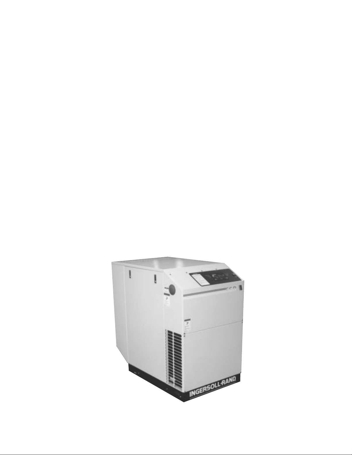
TYPICAL UNIT
1

TABLE OF CONTENTS
0.0 SAFETY AND WARNINGS
0.1 safety instructions
0.2 safety precautions
0.3 decals
1.0 RECEIPT OF EQUIPMENT
1.1 inspection
1.2 unpacking and handling
1.3 tools
2.0 INSTALLATION
2.1 ventilation
2.2 foundation requirements
2.3 piping
2.4 electrical installation
2.5 outdoor sheltered installation
3.0 INTELLISYS
3.1 emergency stop switch
3.2 power on light
3.3 power indicator light
3.4 push buttons
3.5 setpoint procedure
3.6 warnings
3.7 alarms
4.0 SYSTEMS
4.1 general systems
4.2 aircooled compressors
4.3 coolant system
4.4 compressed air system
4.5 coolant/air separation system
4.6 electrical system
4.7 capacity control
5.0 MAINTENANCE
5.1 maintenance schedule
5.2 maintenance records
5.3 maintenance procedures
5.4 sheave alignment
5.5 v-belts
5.6 belt tension adjustment
5.7 shaft seal replacement
5.8 inlet air filter
5.9 coolant filter element
5.10 coolant
5.11 separator tank scavenge
check valve/orifice/screen
5.12 temperature control valve element
replacement
5.13 coolant separator element
5.14 cooler cores: cleaning
5.15 motor lubrication
5.16 long term storage
5.17 coolant/lubricant changeout
5.18 intellisys removal
5.19 coolant hoses
5.20 airend discharge hose
6.0 TROUBLE SHOOTING
7.0 OPTIONS
7.1 remote start/stop
7.2 remote start/stop, PORO
7.3 sequencer control
8.0 REFERENCE DRAWINGS
8.1 electrical schematic - full voltage
8.2 electrical schematic - star-delta
8.3 electrical schematic - full voltage
remote mounted starter
8.4 foundation plan - enclosed
8.5 foundation plan - unenclosed
8.6 foundation plan - outdoor modification
8.7 basic flow schematic - full voltage
8.8 basic flow schematic - full voltage with
modulation
8.9 basic flow schematic - star-delta
8.10 basic flow schematic - star-delta with
modulation
8.11 typical system flow diagrams
9.0 MAINTENANCE RECORD
GENERAL INFORMATION
Weight: See foundation plan, Section 8.0
Cooling Air Flow: See foundation plan, Section 8.0
Ambient Temperature Limit: 35°F to 115°F (2°C to 46°C)
Coolant: Factory Filled SSR Ultra Coolant
Coolant Change: 8000 hours or two years, whichever
comes first
Coolant Capacity: Tank only: 0.75 gal. (2.8 liters)
Complete System: 1.70 gal. (6.4 liters)
Discharge Temperature Limit: 228°F (109°C)
Power Inlet Wiring: Recommended conduit: metallic
flexible Greenfield, or equivalent,
Tools: U.S. Standard and metric are required
to perform maintenance
2
3
0.0 SAFETY AND WARNINGS
0.1 SAFETY INSTRUCTIONS Before you install this air compressor you should take the time to carefully read all the instructions contained in this manual.
Electricity and compressed air have the potential to cause
severe personal injury or property damage.
Before installing, wiring, starting, operating or making any
adjustments, identify the components of the air
compressor using this manual as a guide.
The operator should use common sense and good
working practices while operating and maintaining this
unit. Follow all codes, pipe adequately, understand the
starting and stopping sequence. Check the safety devices
by following the procedure contained in this manual.
Maintenance should be done by qualified personnel,
adequately equipped with proper tools. Follow the
maintenance schedules as outlined in the operators
manual to ensure problem free operation after start up.
Safety instructions in the operators manual are bold-faced
for emphasis. The signal words DANGER, WARNING and
CAUTION are used to indicate hazard seriousness levels
as follows:
Danger is used to indicate the presence of
a hazard which
D! DANGER
! WARNING
! CAUTION
NOTICE
WARNING
COMPRESSED AIR AND ELECTRICITY
ARE DANGEROUS.
BEFORE DOING ANY WORK ON THIS
UNIT, BE SURE THE ELECTRICAL SUPPLY
HAS BEEN CUT OFF–LOCKED & TAGGED
AND THE ENTIRE COMPRESSOR SYSTEM
HAS BEEN VENTED OF ALL PRESSURE.
1. Do not remove the covers, loosen or
remove any fittings, connections or
devices when this unit is in operation. Hot
liquid and air under pressure that are
contained within this unit can cause
severe injury or death.
2. The compressor has high and
dangerous voltage in the motor starter and
control box. All installations must be in
accordance with recognized electrical
codes. Before working on the electrical
system, be sure to remove voltage from
the system by use of a manualdisconnect-switch. A circuit breaker or
fuse safety switch must be provided in the
electrical supply line leading to the
compressor.
Those responsible for installation of this
equipment must provide suitable grounds,
maintenance clearance and lightning
arrestors for all electrical components as
stipulated in O.S.H.A. 1910.308 through
1910.329.
3. Do not operate the compressor at higher
discharge pressure than those specified
on the Compressor Nameplate or motor
overload will occur. This condition will
result in compressor motor shutdown.
4. Use only safety solvent for cleaning the
compressor and auxiliary equipment.
5. Install a manual shut off valve (isolation
type) in the discharge line. When a safety
valve is installed between the isolation
valve and the compressor, it must have
sufficient capacity to relieve the full
capacity of the compressor(s).
6. Whenever pressure is released through
the pressure relief valve, it is due to
excessive pressure in the system. The
cause for the excessive pressure should
be investigated immediately.
7. Before doing any mechanical work on
the compressor:
a.) Shut the unit down.
b.) Electrically isolate the compressor by
use of the manual disconnect switch in the
power line to the unit. Lock and tag the
switch so that it cannot be operated.
c.) Vent pressure from the compressor and
isolate the unit from any other source of
air.
8. There can be adverse effects if
compressor lubricants are allowed to
enter plant air systems.
Air line separators, properly selected and
installed, will minimize any liquid carryover.
The use of plastic bowls on line filters
without metal guards can be hazardous.
From a safety standpoint, metal bowls
should be used on any pressurized
system. Review of your plant air line
system is recommended.
9. When a receiver is installed, it is
recommended that occupational safety
and health standards as covered in the
Federal Register, Volume 36, number 105,
part 11, paragraph 1910.169 be adhered to
in the installation and maintenance of this
receiver.
10. Before starting the compressor, its
maintenance instructions should be
thoroughly read and understood.
11. After maintenance functions are
completed, covers and guards must be
replaced.
0.2 SAFETY PRECAUTIONS
SAFETY PRECAUTIONS
BEFORE PROCEEDING, READ CAREFULLY BEFORE INSTALLING THE
COMPRESSOR OR PERFORMING ANY MAINTENANCE
will cause severe
injury, death, or substantial property
damage if the warning is ignored.
Warning is used to indicate the presence of
a hazard which
injury, death, or substantial property
damage if the warning is ignored.
Caution is used to indicate the presence of
a hazard which
personal injury or property damage if the
warning is ignored.
Notice is used to notify people of
installation, operation, or maintenance
information which is important but not
hazard-related.
can cause severe
will or can cause minor
personal
personal

WARNING
4
Failure to adhere to these recommendations can result in mechanical failure, property damage and serious injury or death.
All air and water inlet, and air and water discharge pipework to and from the inlet and discharge port connections must take
into account vibration, pulsations, temperature, maximum pressure applied, corrosion and chemical resistance. In addition,
it should be noted that lubricated compressors will discharge some oil into the air stream; therefore, compatibility between
discharge piping, system accessories and software must be assured.
For the foregoing reasons, the use of plastic piping, soldered copper fittings and rubber hose as discharge piping is not
recommended. In addition, flexible joints and/or flex lines can only be considered for such purposes if their specifications fit
the operating parameters of the system.
It is the responsibility of the installer and owner to provide the appropriate service pipework to and from the machine.
WARNING
CHECK HIGH AIR TEMPERATURE
There is a high discharge air temperature shutdown function built into the Intellisys on each compressor. It is factory pre-set
at 228°F (109°C). This function should be checked at regular intervals for proper operation, once a month is recommended.
The procedure is:
1. Block off the cooling air discharge.
2. The compressor discharge temperature will rise at a rapid rate. Shutdown should occur when the discharge
temperature reaches the pre-set maximum discharge air temperature setting of the Intellisys. The display should
indicate “HIGH AIREND TEMP” and the alarm light will be illuminated.
The actual temperature at which shutdown occurs should be recorded for comparison to the Intellisys set point and with
similar future test results.
SAFETY SHUTDOWN
!
!
!
“Ingersoll-Rand air compressors are not designed, intended, or approved for breathing air applications. Ingersoll-Rand does
not approve specialized equipment for breathing air application and assumes no responsibility or liability for compressors
used for breathing air services.”
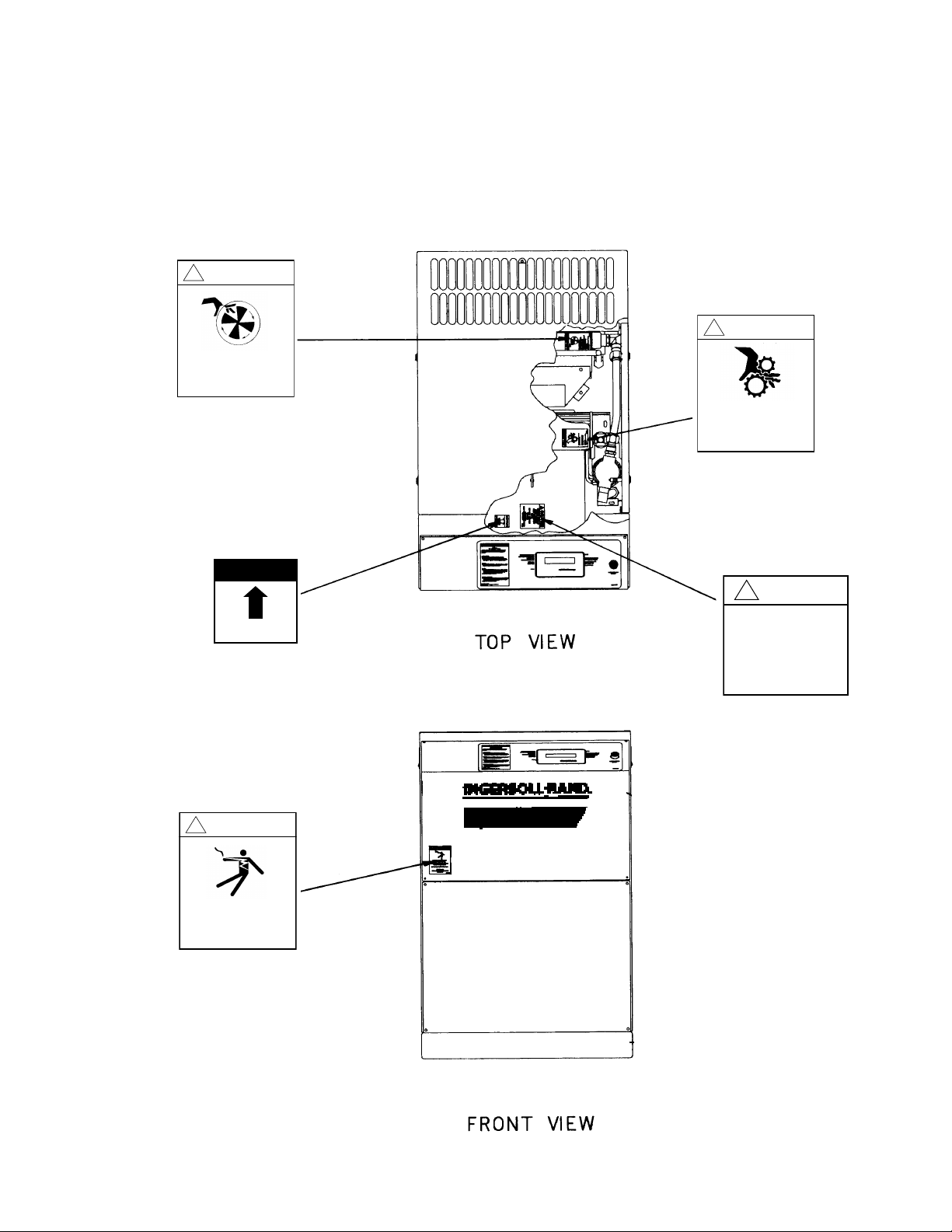
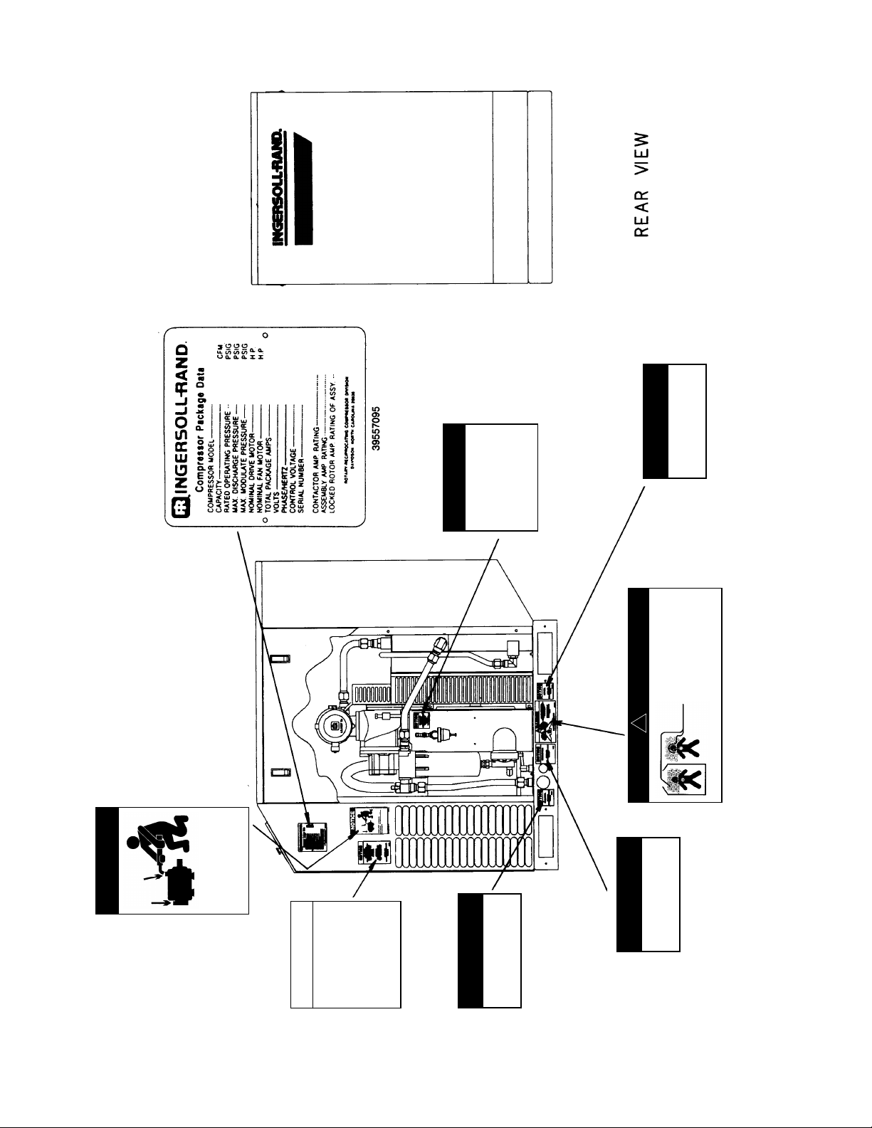
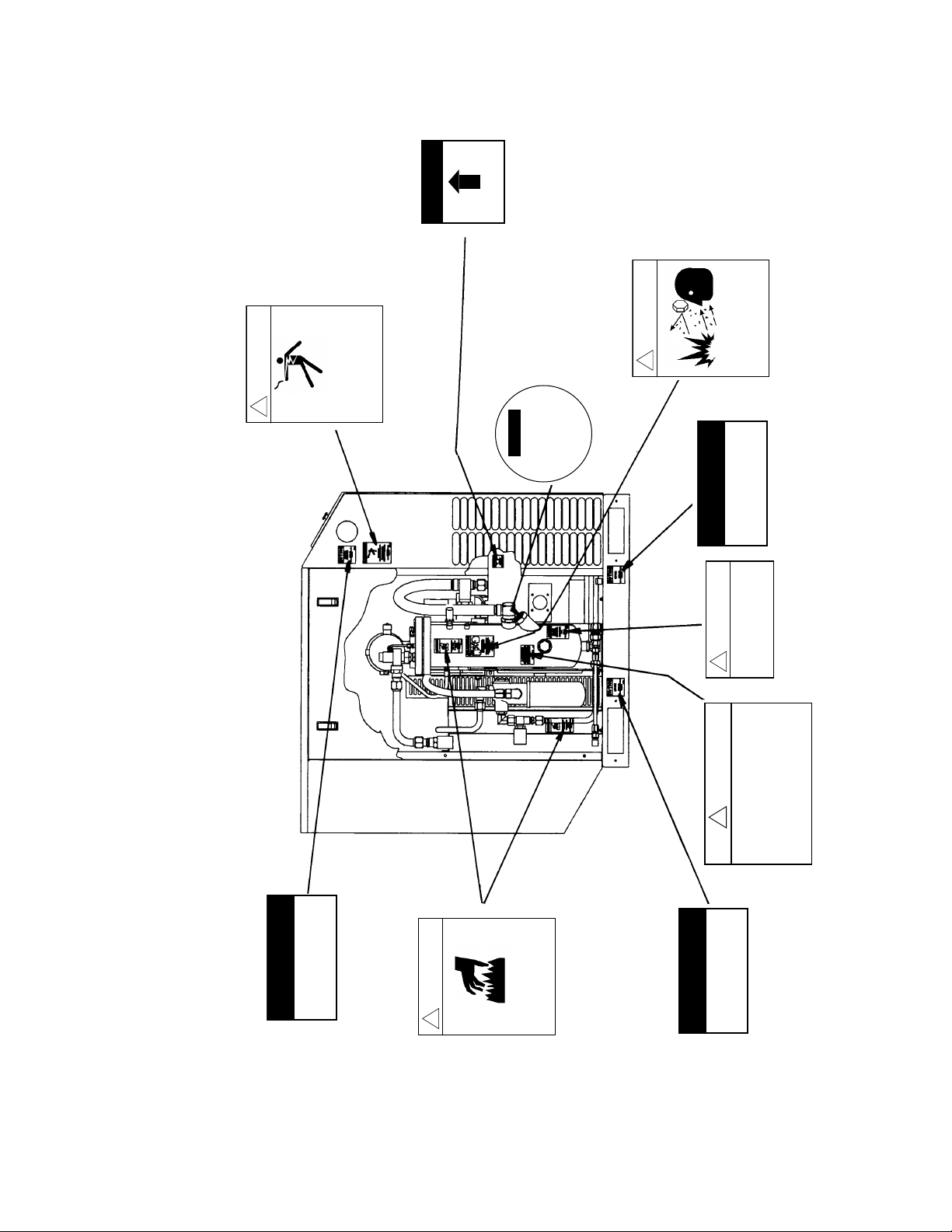
0.3 DECALS
WARNING
!
Exposed fan blade. Can cause severe
injury.
Do not operate with covers removed.
Disconnect power.Lock and tag.
INGERSOLLrAND ®
39558788
39559646
39544150
WARNING
!
Exposed moving parts.
Can cause severe
injury or death.
Stay clear or moving
parts when machine is operating.
INGERSOLLrAND ®
WARNING
!
Hazardous voltage. Can cause
severe injury or death.
Disconnect power before servicing.
Lockout/Tagout machine.
INGERSOLLrAND ®
CAUTION
!
Incorrect lifting of
machine can cause injury
or property damage.
Lift only from base
channels.
INGERSOLLrAND ®
NOTICE
Rotation.
INGERSOLLrAND ®
This section contains representative examples of decals
which will be appearing throughout this manual and are
applied to the compressor unit. If for some reason a
decal is defaced, painted over, or parts are replaced, we
recommend that you obtain a replacement kit as listed in
the spare parts section of the Parts List Manual (Form
APDD 568).
39540174
39540232
5
Condensate drain.
NOTICE
INGERSOLLrAND®
Lift here.
NOTICE
INGERSOLLrAND®
NOTICE
Motors MUST be greased
periodically. See Operators
Manual for procedure.
39570098
39540273
NOTICE
For detailed
regulation adjustment
instructions refer
to Operators/
Instruction Manual.
INGERSOLLrAND ®
39540208
39541081
39570098
NOTICE
To obtain satisfactory compressor
operation and maintenance a
minimum of 3 feet clearance on 3
sides is required 3-1/2 feet is
required in front of the control panel
(or minimum required by latest
National Electrical code or applicable
local codes).
Refer to the Instruction / Operators
Manual before performing any
maintenance.
INGERSOLLrAND ®
39540158
Condensate drain.
NOTICE
INGERSOLLrAND®
39541081
6
DANGER
!
Discharge air.
Can contain carbon monoxide or
other contaminants. Will cause
severe injury or death.
Do not breathe this air.
INGERSOLLrAND ®
39557236
RIGHT SIDE VIEW
CAUTION
!
Use of incorrect coolant can cause
system contamination.
Use only SSR ULTRA COOLANT.
INGERSOLLrAND ®
Electrical power inlet.
NOTICE
INGERSOLLrAND®
39544150
NOTICE
Rotation.
INGERSOLLrAND ®
WARNING
!
Hot surface.
Can cause severe injury.
Do not touch. Allow to cool before
servicing.
INGERSOLLrAND ®
39541362
39540273
WARNING
!
Hazardous voltage. Can cause
severe injury or death.
Only use factory supplied inlet for
incoming power.See Operators/
Instruction manual.
INGERSOLLrAND ®
39543764
39543921
NOTICE
Filler Cap.
Use only recommended
coolant.
Read instruction book
before servicing.
39543921
WARNING
!
High pressure air.
Can cause severe injury or death.
Relieve pressure before removing filter
plugs / caps, fittings or covers.
INGERSOLLrAND ®
39541354
Lift here.
NOTICE
INGERSOLLrAND®
Lift here.
NOTICE
INGERSOLLrAND®
CAUTION
!
IMPROPER COOLANT FILTER REPLACEMENT
WILL CAUSE COMPRESSOR DAMAGE.
REPLACE FILTER ELEMENT AFTER FIRST
150 HOURS OF OPERATION; AND EVERY 1200
HOURS THEREAFTER OR WHEN COOLANT IS
CHANGED.
INGERSOLLrAND ®
39557244
39540240
39540273
39540265
7
8
WARNING
!
Hazardous voltage. Can cause
severe injury or death.
Disconnect power before servicing.
Lockout/Tagout machine.
INGERSOLLrAND ®
39540174
39838396 (UNITS W/FV STARTER)
39838412 (UNITS W/SD STARTER)
39845037 (UNITS W/REMOTE FV STARTER)
39539127 (S/2 FV)
39539135 (S/2.3, S/3 FV)
39539150 (S/4 FV)
39567656 (S/2 SD)
39539143 (S/2.3, S/3 SD)
UNITS W/BUILT-ON STARTER
ONLY
1.0 RECEIPT OF EQUIPMENT
IMPORT ANT
READ THIS
LOST OR DAMAGED GOODS
THOROUGHLY INSPECT THIS SHIPMENT
IMMEDIA TELY UPON ARRIV AL
OUR RESPONSIBILITY FOR THIS SHIPMENT
CEASED WHEN THE CARRIER SIGNED
BILL OF LADING
If goods are received short or in damaged condition, it is important that
you notify the carrier and insist on a notation of the loss or damage
across the face of the freight bill. Otherwise no claim can be enforced
against the transportation company.
If concealed loss or damage is discovered, notify your carrier at once
and request an inspection. This is absolutely necessary. Unless you do
this the carrier will not entertain any claim for loss or damage. The agent
will make an inspection and grant a concealed damage notation. If you
give the transportation company a clear receipt for goods that have been
damaged or lost in transit, you do so at your own risk and expense.
WE, AT I-R, ARE WILLING TO ASSISTYOU IN EVERY POSSIBLE
MANNER TO COLLECT CLAIMS FOR LOSS OR DAMAGE, BUT THE
WILLINGNESS ON OUR PART DOES NOT MAKE US RESPONSIBLE
FOR COLLECTION OF CLAIMS OR REPLACEMENT OF MATERIAL.
THE ACTUALFILING AND PROCESSING OF THE CLAIM IS YOUR
RESPONSIBILITY.
Ingersoll-Rand Company
Davidson, North Carolina
APDDGFO-99-79
SPREADER
BARS
1.1 INSPECTION
When you receive the compressor please inspect it
closely . Any indication of careless handling by the carrier
should be noted on the delivery receipt especially if the
compressor will not be immediately uncrated. Obtaining
the delivery man’s signed agreement to any noted
damages will facilitate any future insurance claims.
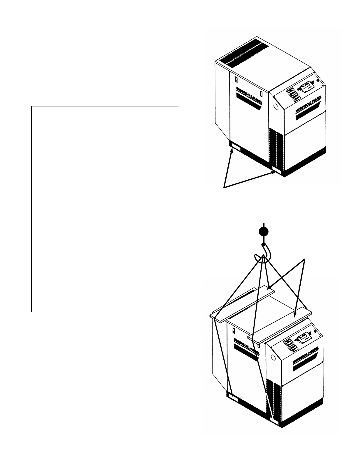
1.2 UNPACKING AND HANDLING
The compressor package has been mounted on a base
which provides for forklifting between the two side
channels to facilitate handling during shipment. Care in
positioning the forklifts is important because the location
of the center of gravity is strongly affected by the location
of the compression module and drive motor.
FORKLIFT PADDING
WILL REDUCE SCRATCHES
AND MARS
Slings can be used to lift the crates, but spreader bars
must be used to prevent the slings from exerting a force
against the sides of the crates.
1.3 TOOLS
Remove compressor unit from wooden skid. Acrowbar
and hammer will be needed.
9
2.0 INST ALLATION
AIR INTAKE
CHEMICALS
METAL
FILINGS
PAINT
SPRAY
OVERSPRAY
Do not use plastic pipe, soldered copper
fittings or rubber hose for discharge piping.
WARNING
Never elevate the compressor unit
above the floor level. This may allow air
to enter the cabinet under the base.
Performance will be affected.
NOTICE
!
!
36” (.9 m)
42” (1.06 m) OR
CODE MINIMUM
10
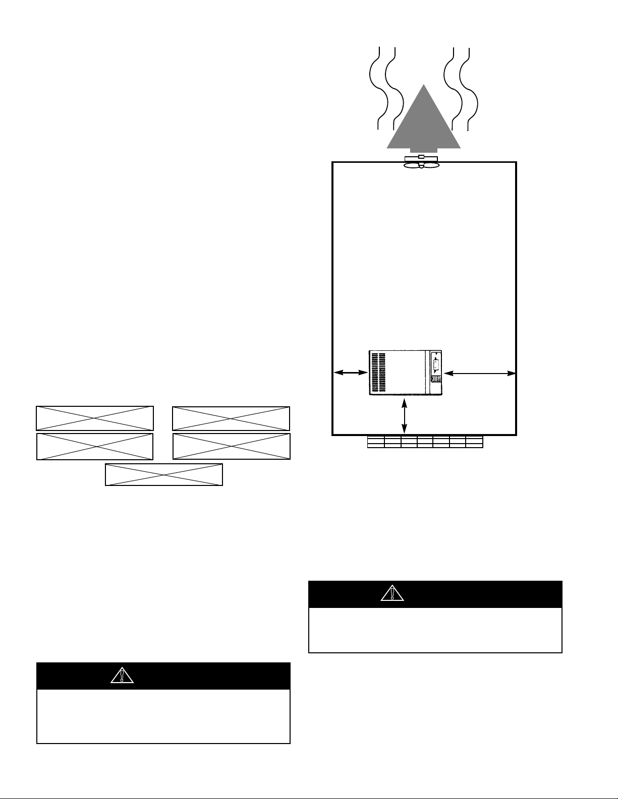
2.1 VENTILATION
Oil flooded rotary air compressors produce large
amounts of heat. Because of this large heat production,
the compressor must be placed in a room with adequate
ventilation. Aroom in which the amount of air that is
drawn in and exhausted is equal to or greater than the
cooling fan air flow requirement for the compressor that
is installed.
If heated air from the compressor exhaust is allowed to
recirculate back to the compressor, the compressor will
overheat and shut down. This heat must be exhausted
from the room. You should take this into consideration
when you decide where to place the compressor within
your plant. Consider that the required maintenance
clearance is 3 ft (.9 m) all around the compressor.
However 42” (1.06m), or minimum required by latest
NEC or applicable local codes, must be maintained in
front of control panel.
Ambient temperatures higher than 115°F (46°C)
should be avoided as well as areas of high humidity.
Consider also the environment surrounding or near
the compressor. The area selected for the location of
the compressor should be free of dust, chemicals,
metal filings, paint fumes and overspray.
DUST
2.2 FOUNDATION REQUIREMENTS
Refer to the foundation plan for the particular model
compressor to be installed. See Section 8.0.
The compressor can be installed on any level floor that is
capable of supporting it. Compressor weights are listed
on the foundation plans.
When sound transmission is of particular importance it is
often helpful to install a sheet of rubber-fabric-matting, or
cork under the compressor to reduce the possibility of
resonant sounds being transmitted or amplified through
the floor.
36”
(.9 m)
2.3 PIPING
The use of plastic bowls on line filters without metal
guards can be hazardous. Their safety can be affected
by either synthetic lubricants or the additives used in
mineral oil. From a safety standpoint, metal bowls should
be used on any pressurized system. Review of your plant
air line system is recommended.
The built-in aftercooler reduces the discharge air
temperature well below the dew point (for most ambient
conditions), therefore, considerable water vapor is
condensed. To remove this condensation, each
compressor with built-in aftercooler is furnished with a
combination condensate separator/trap.
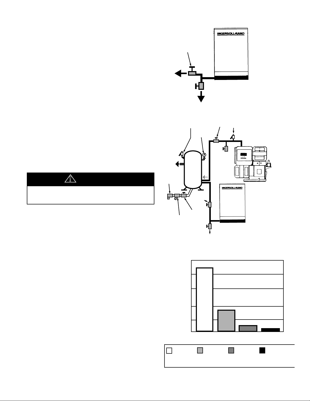
ISOLATION
VALVE
DRIP LEG
ISOLATION
VALVE
ISOLATION
VALVE
STRAINER
TRAP
NOTE:
SEPARATE LINES
GOING TO THE
RECEIVER
DRIP
LEG
ROTARY
COMPRESSOR
PRESSURE
GAUGE
SAFETY
VALVE
ISOLATION
VALVE
RECIPROCATING
COMPRESSOR
DRIP
LEG
SAFETY
VALVE
Careful review of piping size from the compressor
connection point is essential. Length of pipe, size of pipe,
number and type of fittings and valves must be
considered for optimum efficiency of your compressor.
It is essential when installing a new compressor to review
the total plant air system. This is to ensure a safe and
effective total system.
Liquid water occurs naturally in air lines as a result of
compression. Moisture vapor in ambient air is
concentrated when pressurized and condenses when
cooled in downstream air piping.
Moisture in compressed air is responsible for costly
problems in almost every application that relies on
compressed air. Some common problems caused by
moisture are rusting and scaling in pipelines, clogging of
instruments, sticking of control valves, and freezing of
outdoor compressed air lines. Any of these could result in
partial or total plant shutdown.
Compressed air dryers reduce the water vapor concentration and prevent liquid water formation in
compressed air lines. Dryers are a necessary companion
to filters, aftercoolers, and automatic drains for improving
the productivity of compressed air systems.
NOTICE
!
2.3 PIPING (Continued)
200
160
120
80
40
0
DEW POINT
without
Aftercooling
100°F/38°C
(with
Aftercooler)
35°F /1.7°C
(Refrigerated
Dryer)
-40°F/-40°C
(Desiccant
Dryer)
Gallons of Water/24
hours/1000 acfm
ROTARY
COMPRESSOR
A dripleg assembly and isolation valve should be
mounted near the compressor discharge. Adrain line
should be connected to the condensate drain in the
base.
IMPORT ANT: The drain line must slope downward from
the base to work properly.
NOTE: For ease of inspection of the automatic drain trap
operation, the drain piping should include an open funnel.
It is possible that additional condensation can occur if the
downstream piping cools the air even further and low
points in the piping systems should be provided with
driplegs and traps.
IMPORT ANT: Discharge piping should be at least as
large as the discharge connection at the compressor
enclosure. All piping and fittings must be suitable for the
maximum operating temperature of the unit and, at a
minimum, rated for the same pressure as the
compressor sump tank.
DISCHARGE PIPING WITH AFTERCOOLER
Do not use the compressor
to support the discharge pipe.
ROTARY-RECIP IN PARALLEL
MOISTURE CONTENT OF COMPRESSED AIR
11
Two types of dryers, refrigerated or desiccant, are used
ISOLATION
VALVE
ISOLATION
VALVE
STRAINER
TRAP
DRIP
LEG
ROTARY
COMPRESSOR
PRESSURE
GAUGE
SAFETY
VALVE
ISOLATION
VALVE
ROTARY
COMPRESSOR
DRIP
LEG
1FU 2FU 3FU 4FU/5FU
Transformer Primary Primary Secondary Secondary
Rating Fuse Fuse Fuse Fuse
(VA) (Amp) (Amp) (Amp) (Amp)
230 2.0 2.0 2.0 2.0
330 2.5 2.5 3.2 2.0
FUSE TABLE
to correct moisture related problems in a compressed air
system. Refrigerated dryers are normally specified where
compressed air pressure dew points of 33°F (1°C) to
39°F (4°C) are adequate. Desiccant dryers are required
where pressure dew points must be below 33°F (1°C).
Contact your local Ingersoll-Rand distributor for
assistance in selecting correct Ingersoll-Rand filtration or
drying products.
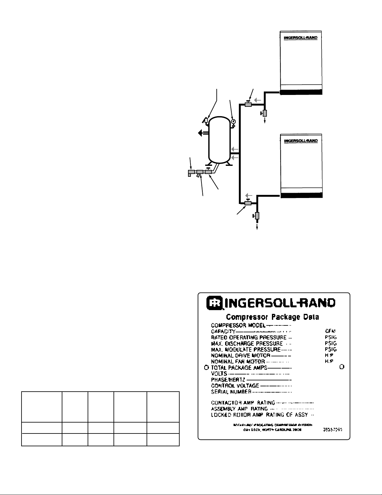
NOTE: Screw type compressors should not be installed
in air systems with reciprocating compressors without a
means of pulsation isolation, such as a common receiver
tank. We recommend both types of compressor units be
piped to a common receiver utilizing individual air lines.
When two rotary units are operated in parallel, provide
an isolation valve and drain trap for each compressor
before the common receiver.
2.4 ELECTRICAL INSTALLATION
Before proceeding further, we recommend that you
review the safety data in the front of this manual.
Locate the compressor data plate on the right side of
starter box.
The data plate lists the rated operating pressure, the
maximum discharge pressure and the electric motor
characteristics and power.
Confirm that the line voltage and compressor nameplate
voltage are the same and that the standard starter box
meets the intent of NEMA 1 guidelines.
Remove the screws and door from the front of the starter
box. Confirm that all electrical connections are made and
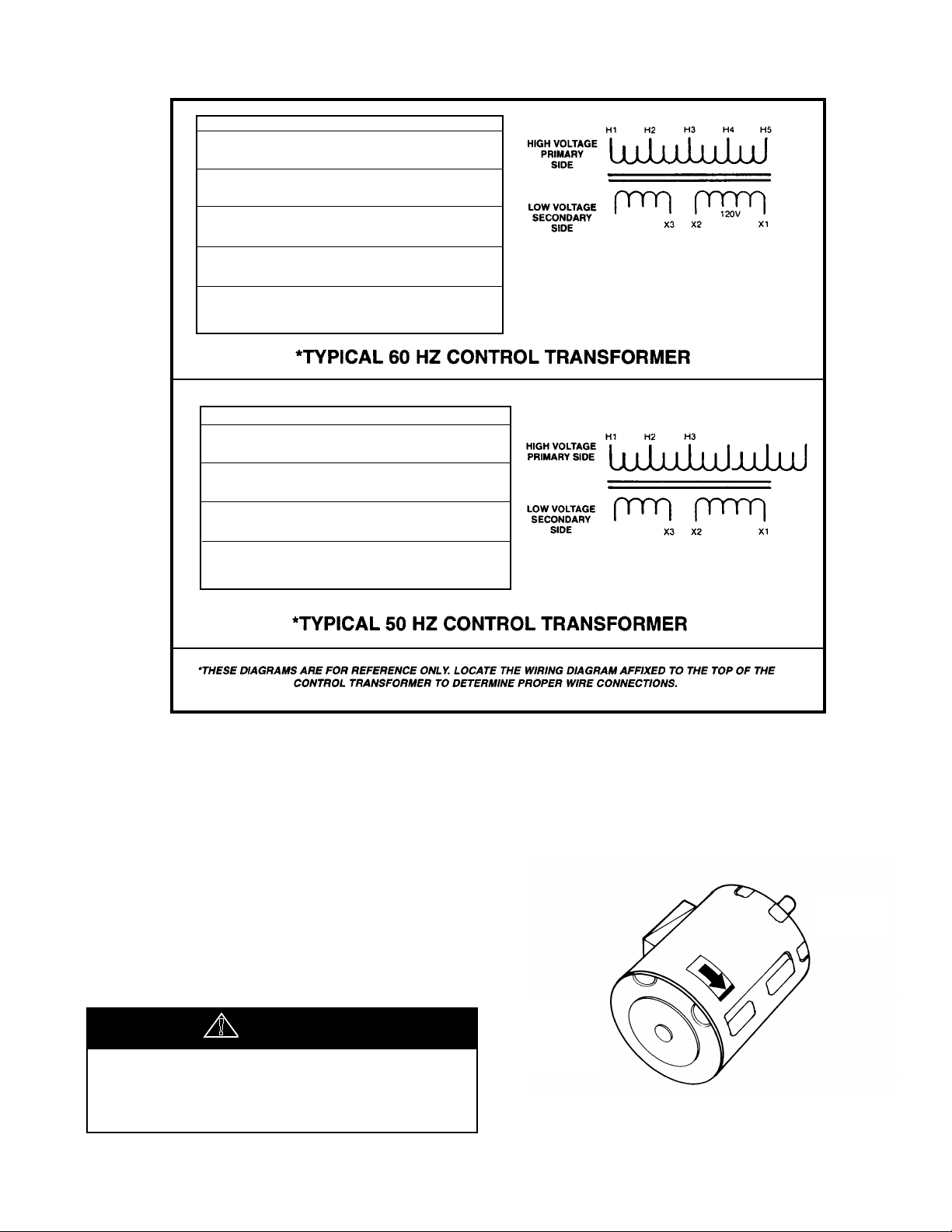
tightened. Confirm that the control transformer is wired
correctly for supply voltage. See Figure 2.4-1 on next
page for typical control transformer wiring.
12
ROTARY TWO COMPRESSOR SYSTEM
CAUTION
ELECTRICAL INSTALLATION (Continued)
Inspect the motor and control wiring for tightness.
Replace the starter box door.
Rotation Check
Locate the rotation decal on the motor.
Drive Motor
The correct compressor drive motor rotation is
clockwise when viewed from the rear or non-drive
end of the motor. See Figure 2.4-2.
!
DRIVE
END
NON-DRIVE
END
110V
LINE VOLTS HZ LINE SEC VOLTS LINE
200 60 H4-H5 120 X1-X2
8 X3-X4
8 X4-X5
220/230 60 H3-H5 120 X1-X2
8 X3-X4
8 X4-X5
380 60 H3-H5 120 X1-X2
8 X3-X4
8 X4-X5
440/460 60 H2-H5 120 X1-X2
8 X3-X4
8 X4-X5
575 60 H1-H5 120 X1-X2
8 X3-X4
8 X4-X5
LINE VOLTS HZ LINE SEC VOLTS LINE
220 50 H5-H6 110 X1-X2
8 X3-X4
8 X4-X5
380 50 H4-H6 110 X1-X2
8 X3-X4
8 X4-X5
415 50 H2-H6 110 X1-X2
8 X3-X4
8 X4-X5
550 50 H1-H6 110 X1-X2
8 X3-X4
8 X4-X5
H4
H5
H6
X5
X5
X4
16V
C.T.
X4
16V
C.T.
FIGURE 2.4-1 TYPICAL CONTROL TRANSFORMER WIRING
If the compressor is operated in the
opposite direction of rotation, airend damage
can result and is not warrantable.
FIGURE 2.4-2 DRIVE MOTOR ROT ATION
13
ELECTRICAL INSTALLATION (Continued)
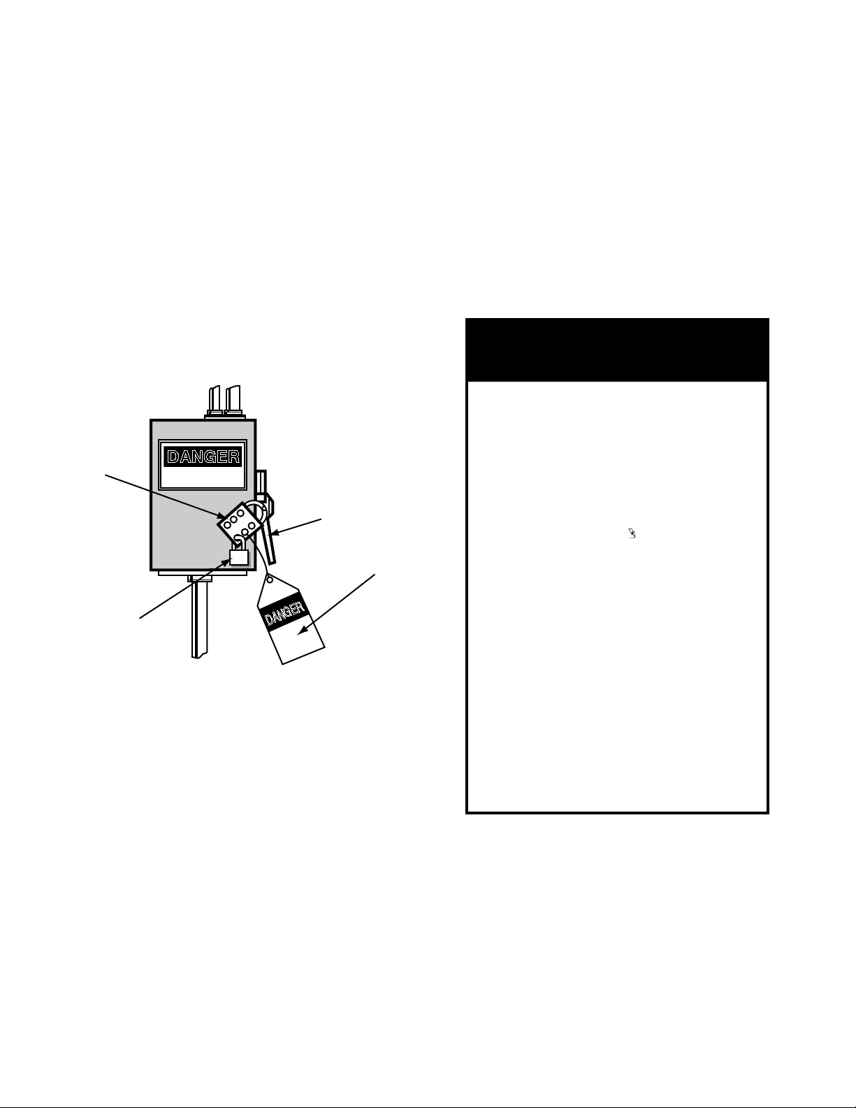
DANGER
HIGH VOLTAGE
DANGER
LEVER
HASP
TAG
KEY LOCK
NOTICE
Intellisys
Operating Instructions
BEFORE INSTALLING, OPERATING, OR PERFORMING ANY
MAINTENANCE ON THIS UNIT, READ AND UNDERSTAND
THE INSTRUCTIONS IN THE OPERATORS / INSTRUCTION
MANUAL
Remove the starter box door.
The Intellisys will automatically shut the unit down if the
compressor rotation is incorrect, and “CHK MTR
ROTATION” will appear in the display, also the alarm
light will be on. See Section 6.
For the compressor motor rotation check, the motor
jogging time must be as short as possible.
After depressing the start button, IMMEDIATELY
depress the “EMERGENCY STOP” button. Should
the motor rotation be incorrect, put main disconnect
in the OFF position, lock and tag. See Figure 2.4-3.
FIGURE 2.4-3 MAIN DISCONNECT
LOCKED AND TAGGED
Interchange any two line connections (L1, L2 or L3) at
the starter. Close and fasten the starter box door.
Recheck for correct rotation.
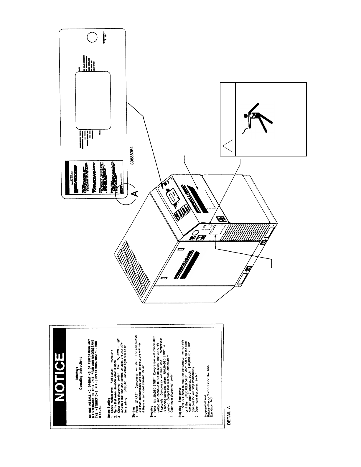
Intellisys Operating Instructions
Read and understand the following Intellisys Operating
Instructions (See Figure 2.4-4) prior to operating the unit.
NOTE: These instructions are also contained on
the decal near the Intellisys panel of the unit.
Before Starting
1. Check coolant level. Add coolant if necessary.
2. Verify that main isolation valve is open.
3. Close main disconnect switch. The “ POWER” light
indicates that line and control voltages are available
for starting. “UNLOAD” indicator light will be on.
Starting
1. Push “START”. Compressor will start. The compressor
will load automatically and the air pressure will rise
if there is sufficient demand for air.
Stopping
1. Push “UNLOADED STOP”. Compressor will immediately
unload and continue to
7 seconds. Compressor will then stop. If compressor
is running unloaded when “UNLOADED STOP” is
pushed, compressor will stop immediately.
2. Open main disconnect switch.
Stopping - Emergency
1. If there is a need to stop the compressor immediately
or if the “UNLOADED STOP” does not stop the compressor after 7 seconds, push “EMERGENCY STOP”
Compressor will stop immediately.
2. Open main disconnect switch.
run unloaded approximately
14
FIGURE 2.4-4 INTELLISYS OPERATING
INSTRUCTIONS

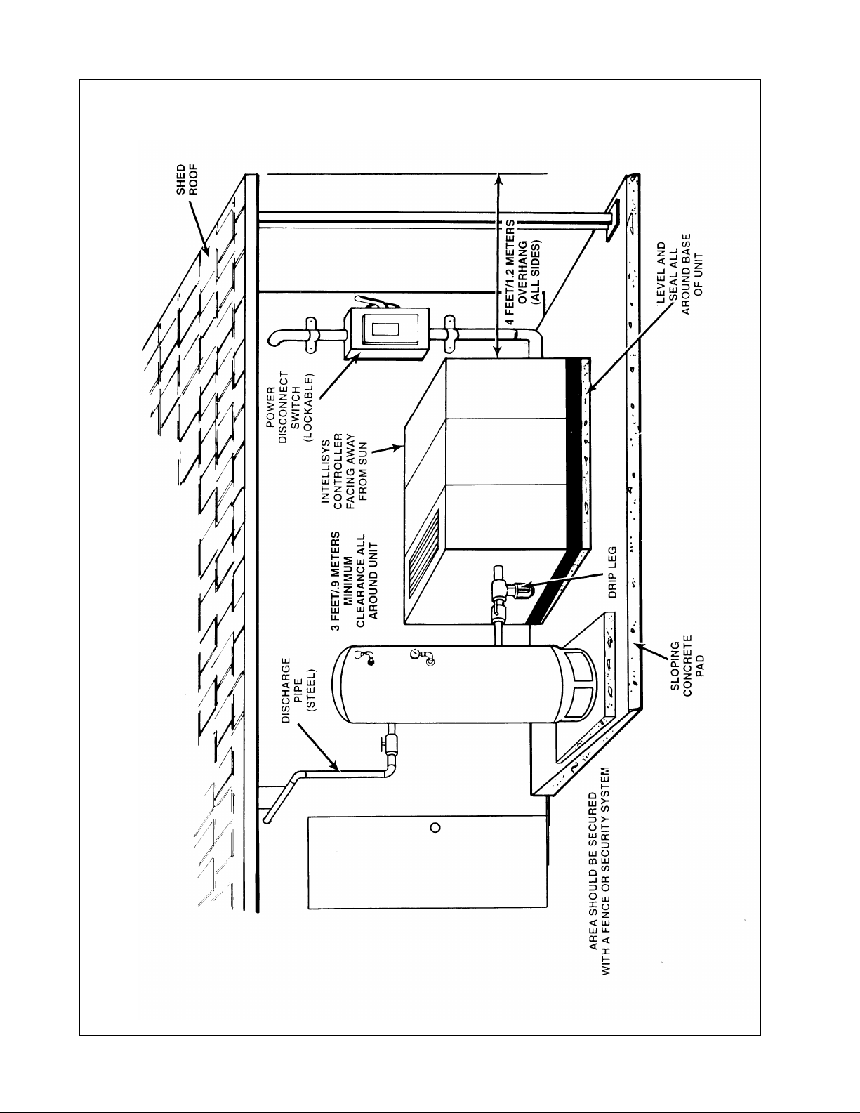
2.5 OUTDOOR SHELTERED INSTALLATION
Many times a compressor must be installed outside due
to jobsite conditions or limited space within a
manufacturing facility. When this occurs there are certain
items that should be incorporated into the installation to
help ensure trouble free operation. These items have
been listed below plus Figure 2.5-1 has been included to
show a typical outdoor sheltered installation. The unit
must be purchased with the Outdoor Modification Option
to provide NEMA 4 electrics and a cabinet exhaust on
the rear of the unit rather than the top to prevent recirculation of cooling air.
■ The compressor should be on a concrete pad
designed to drain water away. If the concrete pad is
sloped, then the compressor must be leveled. In order
to properly pull cooling air through the aftercooler, the
base/skid must be sealed to the concrete pad.
■ The roof of the shelter should extend a minimum of
4 ft (1.2 m) around all sides of the compressor to prevent direct rain and snow from falling on the unit.
■ Air-cooled machines must be arranged under the
shelter in a way that prevents air recirculation (i.e. hot
exhaust back to the package inlet).
■ If the installation includes more than one compressor,
the hot air exhaust should not be directed towards the
fresh air intake of the second unit or an Air Dryer.
■ If a standard machine is to be installed outside, the
ambient temperature must never drop below 35°F
(1.7°C).
■ Power disconnect switch should be within line of sight
and in close proximity to the unit. N.E.C. and local
electrical codes must be followed when installing the
power disconnect switch.
■ Condensate drains must never be allowed to dump on
the ground. Run to a suitable sump for future
collection and disposal or separation of lubricant and
water mixture.
■ Incoming power connections must use suitable
connectors for outdoor weather tight service.
■ A minimum of 3 ft (.9 m) clearance must be allowed
on all four sides of the unit for service access.
However 42” (1.06m), or minimum required by latest
NEC or applicable local code, must be maintained in
front of control panel.
■ If possible, access by a forklift and/or an overhead
beam hoist should be kept in mind (for eventual
service to airend or motor).
■ If the area around the installation contains fine
airborne dust or lint and fibers etc., then the unit
should be purchased with the High Dust Filter Option
and TEFC motor.
■ Some type of protection such as a fence or security
system, should be provided to prevent unauthorized
access.
■ Arrange the machine with the Intellisys con-
troller/starter enclosure facing away from the sun as
radiant heat can affect starter/lntellisys performance.
Also direct sunlight and UV rays will degrade the
membrane touch panel. This is not a warrantable
situation.
15
16
FIGURE 2.5-1 TYPICAL OUTDOOR SHELTERED INSTALLATION
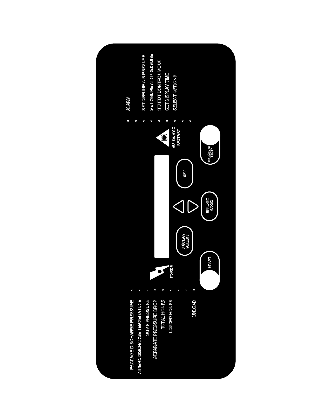
INGERSOLrAND
INTELLISYS
• ALARM•• SET OFFLINE AIR PRESURE
• SET ONLINE AIR PRESSURE
• SELECT CONTROL MODE
• SET DISPLAY TIME
• SELECT OPTIONS
•
•
PACKAGE DISCHARGE PRESSURE •
AIREND DISCHARGE TEMPERATURE •
SUMP PRESSURE •
SEPARATE PRESSURE DROP •
TOTAL HOURS •
LOADED HOURS •
•
•
UNLOAD •
POWER
START
UNLOAD
/LOAD
DISPLAY
SELECT
STOP
UNLOADED
SET
AUTOMATIC
RESTART
3.0 INTELLISYS
INTELLISYS CONTROLLER
INGERSOLLrAND
INTELLISYS
17
3.0 INTELLISYS
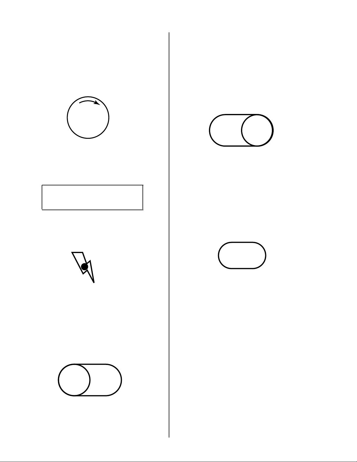
3.1 EMERGENCY STOP SWITCH
Pressing this switch stops the compressor
immediately. Compressor cannot be restarted until
switch is manually reset. Turn clockwise to reset.
3.2 POWER ON LIGHT (Inside Starter Box)
Indicates control voltage is available to the control
circuit and line voltage is available for starting.
POWER ON
3.3 POWER INDICATOR LIGHT
Indicates voltage is available to the intellisys
controller.
3.4 PUSH BUTTONS
START
If the display shows READY TO START, pressing
this button will start the compressor. The
compressor will start and load automatically if there
is a demand for air.
If in the display table press this button to exit the
display table. Display will show “CHECKING
MACHINE” then “READY TO START”.
EMEG
STOP
UNLOAD
/LOAD
START
STOP
UNLOADED
DISPLAY
SELECT
SET
POWER
POWER
UNLOAD STOP
UNLOAD
/LOAD
START
DISPLAY
SELECT
UNLOAD
/LOAD
DISPLAY
SELECT
UNLOAD
/LOAD
START
STOP
UNLOADED
DISPLAY
SELECT
SET
POWER
Pressing this button will activate the unload stop. If
the compressor is running loaded, it will unload.
Seven seconds later it will stop. if the compressor is
running unloaded, it will stop immediately. Pressing
this button with the unit stopped will flash all L.E.D.’s
for a light check and flash the software version
number in the display.
UNLOAD/LOAD
If the unit is running loaded, pressing this button will
cause the unit to unload, the unload indicator light
will be on. The unit will not load until the button is
pressed again. If the unit is running unloaded,
pressing this button will load the unit in the ON/OFF
LINE or MOD/ACS control mode previously
operating.
18
DISPLAY
SELECT
UNLOAD
/LOAD
START
DISPLAY
SELECT
SET
POWER ON
EMEG
STOP
UNLOAD
/LOAD
START
STOP
UNLOADED
DISPLAY
SELECT
SET
POWER
EMEG
STOP
UNLOAD
/LOAD
START
DISPLAY
SELECT
SET
POWER
3.4 PUSH BUTTONS (Continued)
DISPLAY SELECT
Pressing this button will change the information
selected for the display. The display table will be
incremented. If the button is held, this display table
will scroll. This button can also be used to exit the
set point procedure.
NOTE: For readings less than 1 hr., hourmeter
display minutes. After 1 hr. the hourmeter displays
hours.
SET
PRESSURE SENSOR CALIBRATION (ZEROING)
ROUTINE
This routine is entered if the unit is not running and
both the up and down arrows button are pressed at
the same time. Make sure all pressure is relieved
from the compressor before calibration. The display
will flash the message “CALIBRATING”. After
calibration is completed the display will indicate
“READY TO START”. Zeroing should only be done
after a pressure sensor has been replaced or any
controller change.
The SET button is used to enter the set point
procedure. The set button is also used to reset
warnings and alarms. Pressing this button once will
reset a warning, twice will clear an alarm.
ARROWS
These buttons have several functions. If the
Intellisys is in the set point mode, the ARROWS are
used to change the set point values. If the unit has
multiple alarms or warnings, the ARROWS are used
to scroll through these conditions. The ARROWS
have a function in the calibration routine, which will
be described later.
19
 Loading...