

Page 1
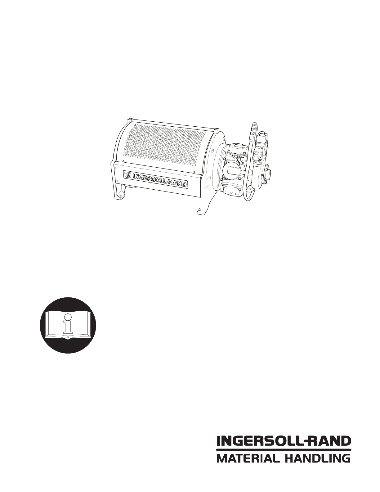
MODEL FA5A AIR WINCH
SUPPLEMENTAL SERVICE
AND MAINTENANCE INSTRUCTIONS
Form MHD56111
This manual contains important service and maintenance information.
Make this manual available to all persons responsible for the service
and maintenance of these products.
Always operate, inspect and maintain this winch in accordance with American National
Standards Institute Safety Code (ASME B30.16) and any other applicable safety codes and
regulations.
Refer all communications to the nearest Ingersoll-Rand Material Handling Office or
Distributor.
Form MHD56111
Edition 2
March 1997
71296438
©
1997 Ingersoll-Rand Company
Page 2

INTRODUCTION
The information contained in this manual is supplemental to
information contained in the FA5A Winch, Parts, Operation and
Maintenance Manual Form number MHD56087.
The information is primarily intended for service and repair
personnel who may be involved with the maintenance of FA5A
Winches. It is recommended that the FA5A Winch Parts,
Operation and Maintenance Manual MHD56087 be read prior to
performing any service or repair work.
This supplement only contains information on the major
subassemblies which are described in separate sections. Refer to
the FA5A Manual for all other information.
INDEX
Section 1. Disc Brake Assembly . . . . . . . . . . . . . . . . . . . . . . . . . . . . . . . . . . . . . . . . . . . . . . . . . . . . . . . . . . . . . . . . . . . . . . . . . . Page 3
Section 2. Manual Band Brake Assembly . . . . . . . . . . . . . . . . . . . . . . . . . . . . . . . . . . . . . . . . . . . . . . . . . . . . . . . . . . . . . . . . . Page 12
Section 3. Automatic Band Brake Assembly . . . . . . . . . . . . . . . . . . . . . . . . . . . . . . . . . . . . . . . . . . . . . . . . . . . . . . . . . . . . . . . Page 22
Section 4. Directional Control Valve Assembly . . . . . . . . . . . . . . . . . . . . . . . . . . . . . . . . . . . . . . . . . . . . . . . . . . . . . . . . . . . . Page 34
Section 5. Reduction Gear Assembly . . . . . . . . . . . . . . . . . . . . . . . . . . . . . . . . . . . . . . . . . . . . . . . . . . . . . . . . . . . . . . . . . . . . . Page 46
SAFETY INFORMATION
This manual provides important information for all personnel
involved with the safe installation, operation and proper
maintenance of this product. Even if you feel you are familiar
with this or similar equipment, you should read this manual
before operating the winch.
Danger, Warning, Caution and Notice
Throughout this manual there are steps and procedures which,
if not followed, may result in an injury. The following signal
words are used to identify the level of potential hazard.
DANGER
WARNING
Danger is used to indicate the presence
of a hazard which will cause severe
injury, death, or substantial property
damage if the warning is ignored.
Warning is used to indicate the presence
of a hazard which can cause severe
injury, death, or substantial property
damage if the warning is ignored.
Caution is used to indicate the presence
of a hazard which will or can cause
injury or property damage if the
warning is ignored.
NOTICE
Notice is used to notify people of
installation, operation, or maintenance
information which is important but not
hazard-related.
2
Page 3
DISC BRAKE - GENERAL INFORMATION
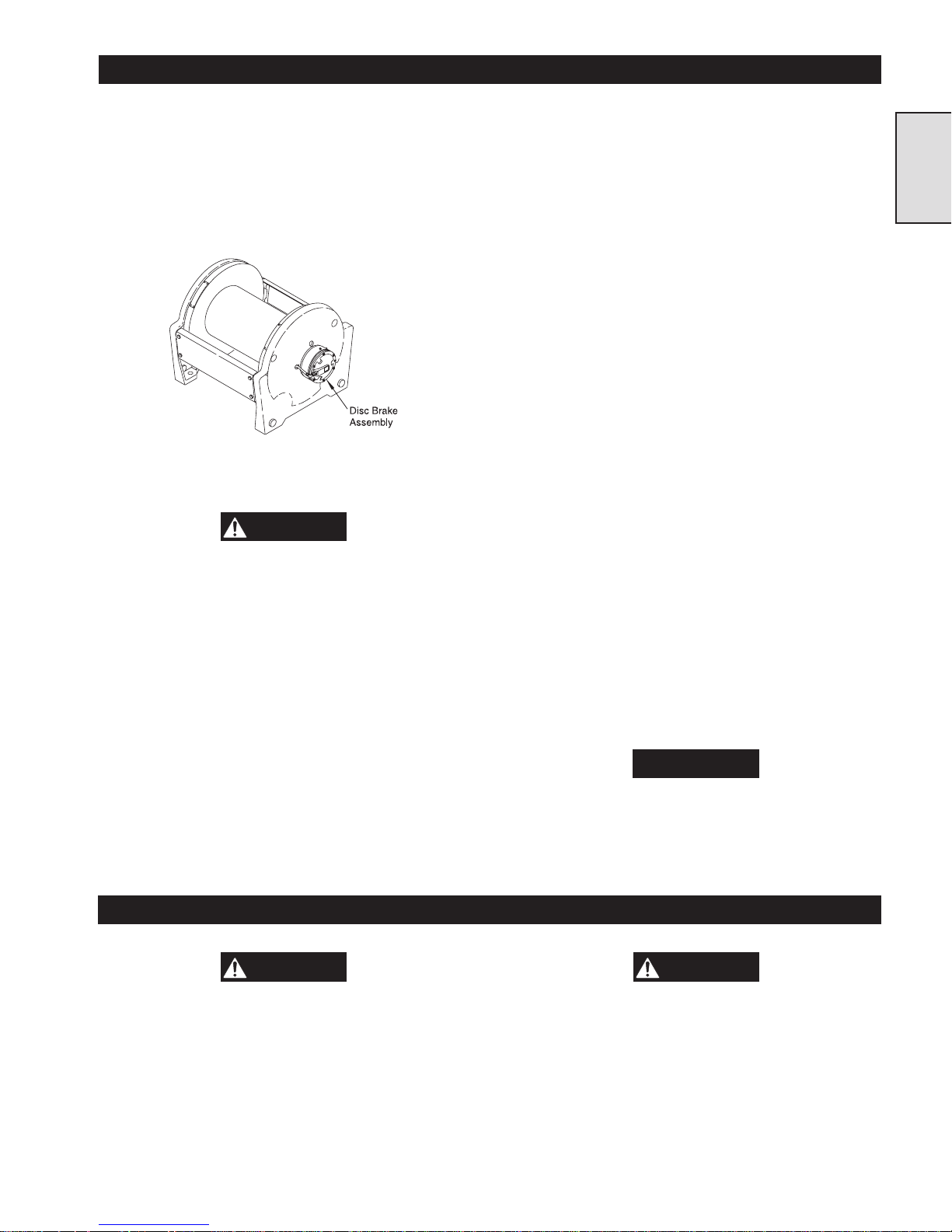
Description
The disc brake for the FA5A winch bolts to the end of the
winch opposite the motor. It has a cylindrical housing
approximately twenty centimeters (eight inches) in diameter and
ten centimeters (four inches) deep. There are eight socket head
bolts located in the end cover. The disc brake has one air line
running to it, a drain plug in the bottom, an oil level plug in the
side, and a vented filler plug on the top.
(Dwg. MHP1218)
Operation
WARNING
Do not use this winch for lifting, supporting, or
transporting people or lifting or supporting loads over
people.
When the winch control handle is moved or the pendant control
is operated, to haul-in the wire rope, a one-way clutch inside the
disc brake allows free rotation of the winch drum without the
need to disengage the brake. When the winch control handle is
released or returned to the neutral position, or the pendant
control button is released, the one-way clutch locks and the disc
brake prevents the wire rope from paying-out. When the winch
control handle is moved or the pendant control is operated to
payout the wire rope, air pressure is directed to the brake. The
air pressure releases the brake, and allows the winch drum to
rotate.
Components
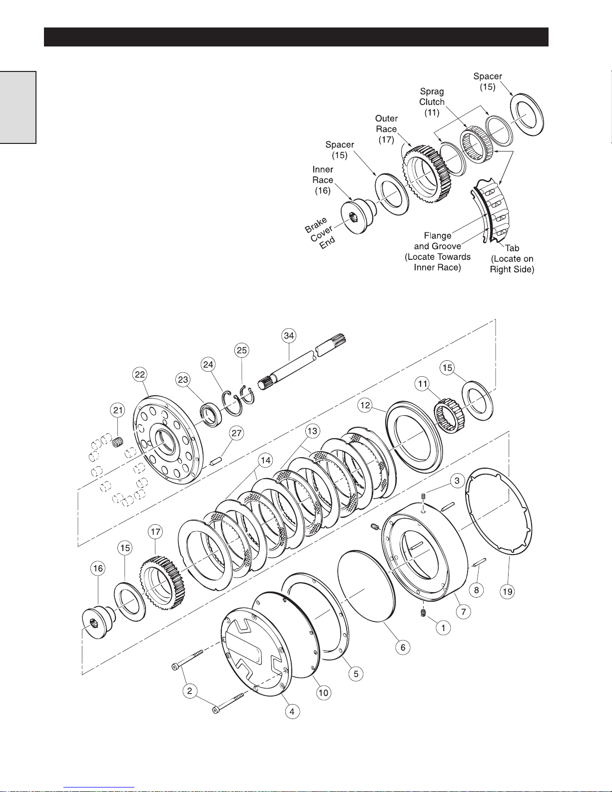
The disc brake is comprised of two main sections. The first is
the housing and end cover plate. Under the cover plate is a
diaphragm assembly. The second section is located in the brake
housing and consists of a pressure plate, twelve springs,
five friction and six separator plates, a one-way clutch with an
inner and outer race, and a bearing pressed into a support plate.
Refer to the parts drawing MHP0850 for additional information.
Function
The disc brake runs in an oil bath shared with the gearbox. The
disc brake housing is bolted to the winch frame. It anchors the
disc brake to the winch frame, and holds the oil that lubricates
the brake. A flexible diaphragm is positioned between the end
cover and the brake housing. When the winch control handle is
moved or the pendant button is pushed to payout the wire rope,
air pressure is introduced to the brake. The air pressure pushes
on the diaphragm, which then presses on a metal diaphragm
plate. The diaphragm plate transfers the force through three pins
to a pressure plate.
Twelve springs constantly press on the pressure plate. The
springs locate in pockets in the support plate. The spring
pressure squeezes the friction and separator plates together,
engaging the brake. The one-way clutch rides on inner and outer
races. The one-way clutch’s inner race rotates in a bearing
inside the support plate, and connects through the brake shaft to
the gearbox and the winch drum. The one-way clutch’s outer
race engages the friction plates which are located between the
separator plates. Three dowel pins align the separator plates and
engage them to the disc brake housing. When the plates are
compressed together and the brake is engaged, there is a solid
connection between the winch drum and the winch frame, and
the winch drum cannot turn. Moving the winch control valve
forward or pressing the pendant button to payout a load causes
air pressure to relieve the spring pressure that compresses the
brake discs together. This allows the winch drum to turn, and
the wire rope to payout.
NOTICE
The dump valve and orifice release air pressure on the
brake at a controlled rate so that the disc brake will
engage promptly.
Section 1
WARNING
Prior to troubleshooting the disc brake, remove the
wire rope from the winch drum. Failure to remove the
wire rope can cause mechanical damage and/or injury.
There are two ways that the disc brake can cause problems:
1. It may fail to release.
2. It may slip or fail to engage properly.
DISC BRAKE TROUBLESHOOTING
WARNING
If the one way clutch has “rolled over” the winch may
have been severely overloaded. If an overload is
suspected, the winch drivetrain components and
brake components (especially the one way clutch and
the inner and outer races) must be closely inspected
for damage, and replaced if necessary. Review the
FA5A winch operating procedures to be sure that the
load does not exceed the rated capacity of the winch.
3
Page 4
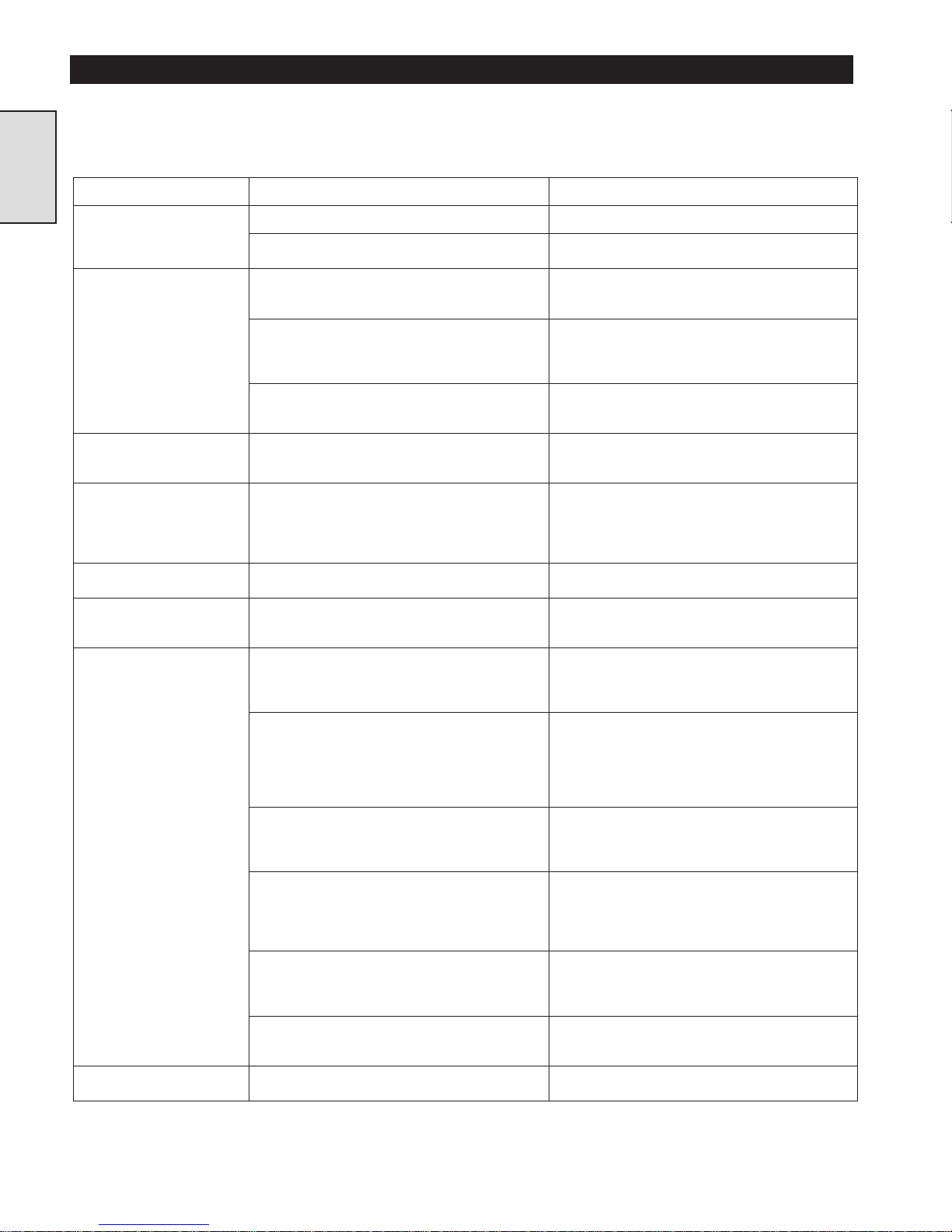
DISC BRAKE TROUBLESHOOTING
This section provides basic troubleshooting information. Specific causes to problems are best identified by thorough inspections
performed by personnel instructed in safety, operation and maintenance of this equipment. The chart below provides a brief guide to
common disc brake symptoms, probable causes and remedies.
Symptom Cause Remedy
Section 1
Air is not reaching the
brake.
The disc brake fails to
release.
Air pressure is applied to
brake at the wrong time.
Air pressure is not being
released from the brake at
the proper time.
The disc brake is not
properly lubricated.
The friction and separator
plates are slipping.
The disc brake slips or does
not engage properly.
Brake housing is extremely
hot.
The air line is not connected to the brake. Make sure the air line is connected to the brake.
The air line is blocked or torn. Make sure that the air line is not blocked, torn or
The diaphragm is leaking. Remove the cover and diaphragm assembly.
The separator plates cannot slide freely on the
three pins.
The friction plates are not free to slide on the
outer race.
The brake activation components in the winch
control valve are out of adjustment, or the control
handle is not returning to neutral.
The orifice and dump valve assembly are not
relieving air pressure from brake.
The wrong amount or type of oil is in the disc
brake and gearbox.
The wrong amount or type of oil is in the disc
brake and gearbox.
The friction plates are worn. Inspect the plates for wear. The plates must not be
The pins are sticking in the housing and are not
allowing free movement of the friction and
separator plates.
The springs have collapsed. Remove and measure the springs. Replace the
The inner race has moved out of position. Check the retainer ring that holds the inner race in
The one-way clutch has "rolled over". Check the rotation of the one-way clutch. Refer to
The brake shaft or inner race is stripped or
broken.
The brake is not releasing on time. Adjust brake release valve. Refer to “Section 4”.
pinched. Replace the air line if necessary.
Inspect the diaphragm for holes or tears, and
replace if necessary.
Remove and inspect the three pins for signs of
galling, ridges or wear. If any signs are found,
replace the pins. Check the separator plates for
signs of wear and replace as needed.
Make sure the plates are free to move on the race.
If the plates are sticking, replace the race and/or
the plates as needed.
Refer to the manual for instructions on
troubleshooting and adjusting the brake activation
components and the winch control valve.
To check, operate the winch control valve handle
or pendant control in the pay-out direction, then
feel and listen for air escaping from the dump
valve. If no air is detected, replace the orifice and
dump valve assembly.
Remove the disc brake oil level plug. Oil should be
just below the level of the oil level hole.
Drain and replace oil from disc brake and gearbox.
Refer to inspection in the “MAINTENANCE”
section.
glazed. If the plates are worn or glazed, replace
them. Refer to inspection in the
“MAINTENANCE” section.
Remove and inspect the three pins for signs of
galling, ridges or wear. If any of these are found,
replace the pins. Inspect the housing and if
necessary ream the holes. If reaming does not
clean up the holes, replace the housing. Refer to
inspection in the “MAINTENANCE” section.
springs if they are below the minimum
measurement. Refer to inspection in the
“MAINTENANCE” section.
place. If it has failed, the race could move and
prevent the diaphragm plate from moving properly.
Replace the retainer ring. Refer to inspection in the
“MAINTENANCE” section.
inspection in the “MAINTENANCE” section. If
the clutch has "rolled over" replace the clutch,
inner and outer races.
Remove and inspect the brake shaft and the inner
race. If either the shaft or race is stripped or
broken, replace both.
4
Page 5
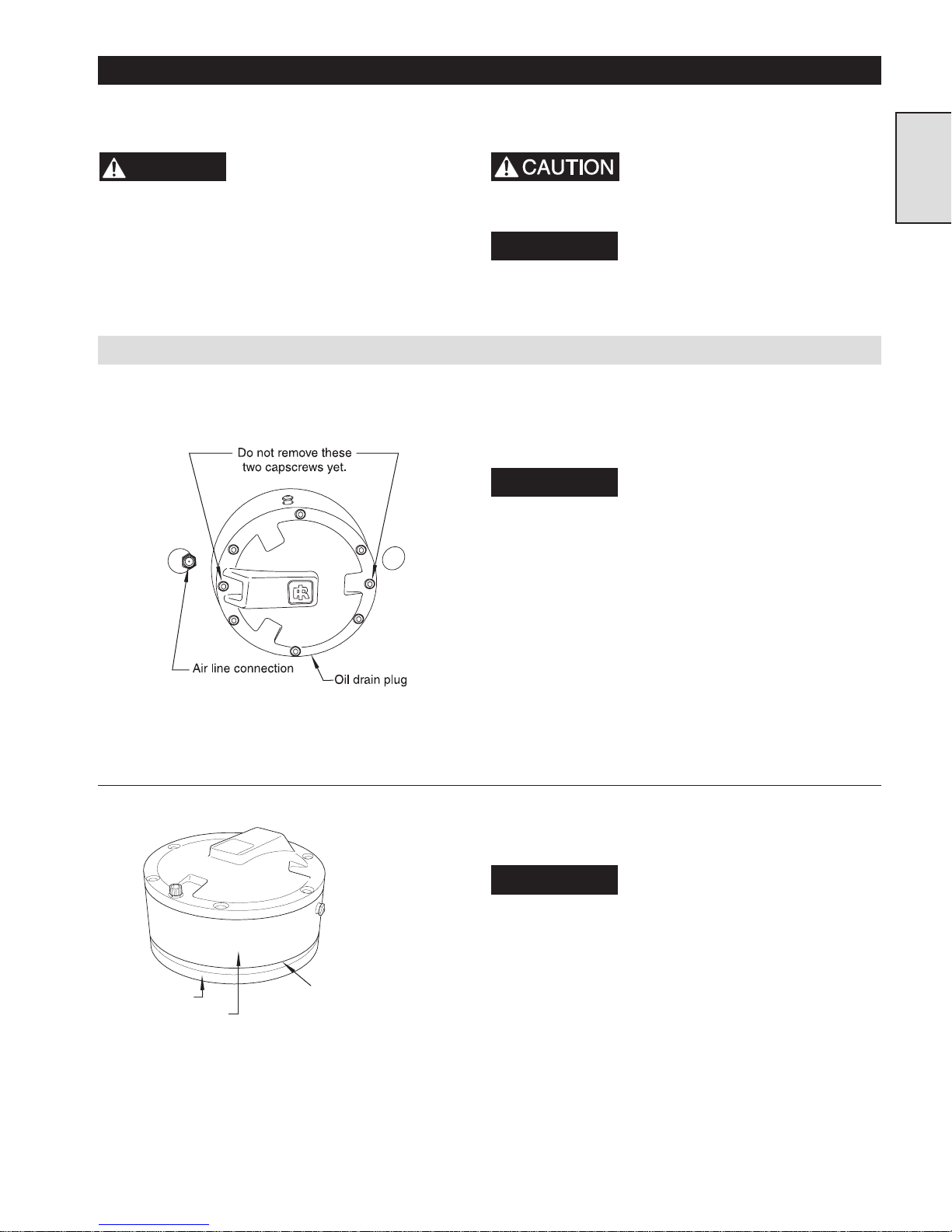
DISC BRAKE MAINTENANCE
Read these instructions completely before working on the disc brake.
WARNING
rope from the winch drum. Failure to shut off the air
and remove the wire rope can cause mechanical
damage and/or injury.
Before working on the disc
brake, shut off the air to the
winch and remove the wire
Disc Brake Removal and Disassembly
(Dwg. MHP0840)
Before working on the disc
brake, lift the vent on top of
the disc brake housing to
discharge any internal pressure.
NOTICE
1. Drain the oil from the brake by removing the drain plug (1) in
the bottom of the disc brake housing (7). Be sure to catch the
oil in a suitable container and discard it in an environmentally
safe manner.
NOTICE
upright after the disc brake housing has been removed.
2. While the oil is draining, disconnect the air line and remove
the orifice and dump valve assembly from the disc brake
housing.
3. Take out the six evenly spaced capscrews (2), but leave the two
that line up with the air fitting. These capscrews fasten the disc
brake assembly together, and should be left in place until the
brake is removed from the winch.
4. Pull the disc brake assembly straight away from the upright
and place it in a drain pan. It may be necessary to use a soft
hammer to loosen the disc brake housing. The splined brake
shaft (34) might come out with the disc brake assembly. If it
does, remove it from the brake assembly and set it aside.
All item numbers shown here
refer to the drawing and parts
list in parts section.
The oil also lubricates the gear
box. If the gearbox has not been
drained, oil will run out of the
Section 1
Support Plate
Disc Brake Housing
(Dwg. MHP0843)
Disc Brake Housing and
Support Plate will seperate
as the Capscrews are
loosened.
5. Lay the disc brake assembly down with the cover facing up.
Loosen the remaining two capscrews by backing them out one
turn at a time.
NOTICE
Spring pressure will separate the
disc brake housing and the
support plate.
5
Page 6
Section 1
(Dwg. MHP0837)
6. Lift the housing and end cover assembly off the support plate
(22), and collect the three dowel pins (8).
7. Separate the housing (7) from the end cover (4) and the
diaphragm assembly.
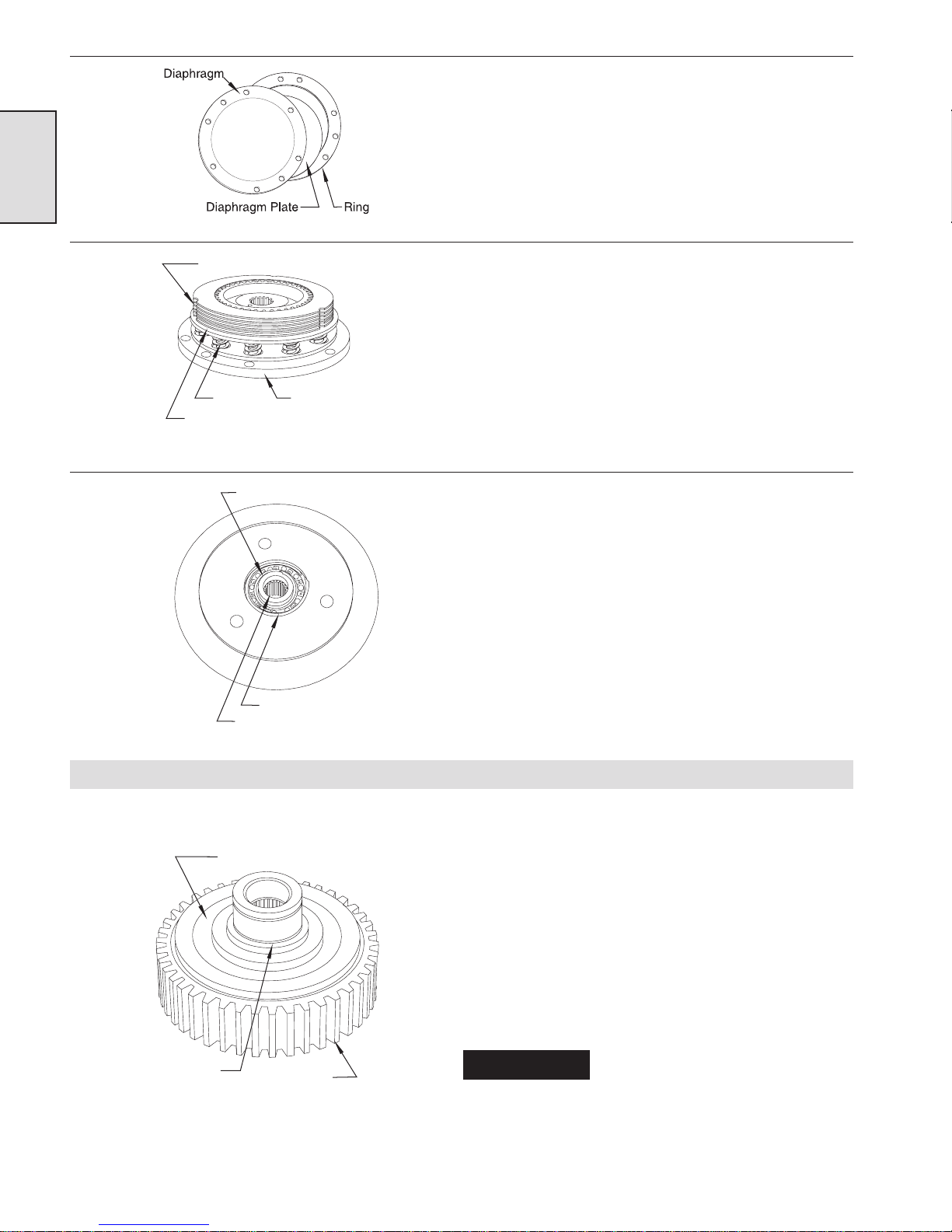
8. Remove and set aside the diaphragm (10), ring (5), and the
diaphragm plate (6).
(Dwg. MHP0769)
(Dwg. MHP0845)
Friction and Separator Plates
Spring Support Plate
Pressure Plate
Clutch Retainer Ring
Bearing Retainer Ring
Inner Race
9. Remove the five fiber covered friction plates (13), six steel
separator plates (14), pressure plate (12), and the twelve
springs (21) from the support plate.
10. Remove the one-way clutch assembly from its bearing (23) in
the support plate by taking off the clutch retainer ring (25).
Press the bearing out of the support plate after removing the
bearing retainer ring (24).
11. Slide the inner race (16) out of the one-way clutch (11), then
slide the one-way clutch (with the wear plates) out of the outer
race (17).
Inspection
One Way Clutch
Inner Race
(Dwg. MHP0848)
Outer Race
1. Check the support plate bearing for signs of wear. Bearing
should rotate freely without sticking or binding. If sticking or
binding is present replace bearing.
2. Inspect the one-way clutch and its inner and outer races for
signs of slipping, scoring, galling, cracking or discoloration.
Replace the one-way clutch and the races if they show any
wear or damage.
3. The fiber covered friction plates (13) must be flat, and should
not be glazed. The grooves should be sharp and even, and there
should be no pieces of fiber missing. The plates should
measure 2 mm ±0.1 mm (0.080 ±0.004 inches). Make sure the
teeth that engage the one-way clutch are not worn or damaged.
Replace any plates that show wear or damage.
NOTICE
that have any pieces of debris embedded.
Do not wash the friction plates in
cleaning solvent. Wipe clean if
needed, and replace any plates
6
Page 7
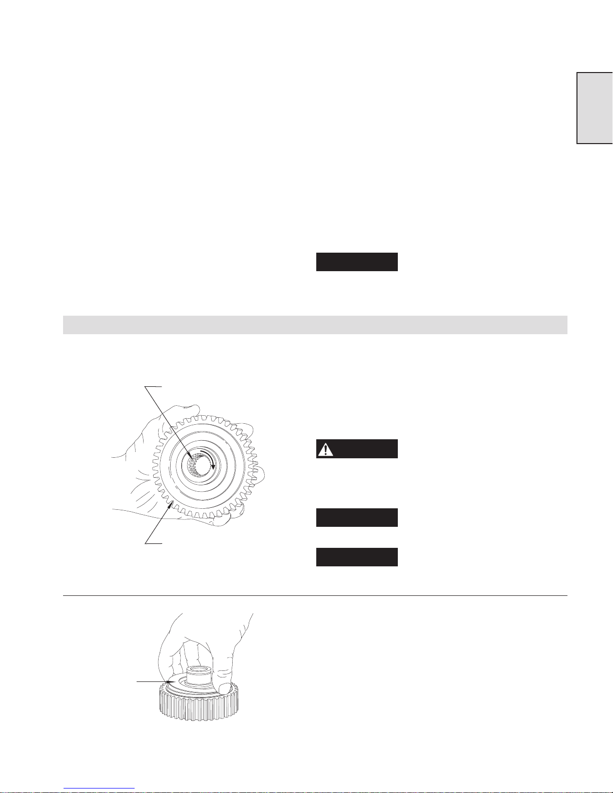
4. The steel separator plates (14) must be flat, and not scored or
discolored. They should measure 1.5 mm ±0.12 mm (0.060
±0.005 inches). The three notches (on the outside of the
separator plates) that engage the pins should not show any
deformation. Inspect the housing, and if necessary ream the
holes to 7.976 ±0.025 mm (0.314 ±0.001 inches). If reaming
does not clean up the holes, replace the housing. Replace any
plates or pins that show signs of wear or damage.
5. The free length of springs should measure at least 25.7 mm
(1.010 inches). Replace any springs that have collapsed or are
bent. Before installing new springs, compress them completely
several times. This will preset the springs to the proper initial
installation height.
6. Closely examine the diaphragm (10) for holes or tears. If there
are any holes or tears, replace the diaphragm. Make sure the
radius on the diaphragm plate is smooth and polished, and
check the diaphragm cover to make sure there are no sharp
edges that might damage the diaphragm.
Section 1
Disc Brake Assembly and Installation
Inner Race
Outer Race
(Dwg. MHP0846)
NOTICE
corresponding surfaces of the housing and cover are
clean and dry.
1. Press the bearing (23) into the support plate (22), and install
the retainer ring (24).
2. Holding the outer race on its side, insert the one-way clutch
with its wear plates (11) partially into the outer race (17).
3. Place one of the spacers (15) against the inner race’s flange
before slipping the inner race (16) inside the one-way clutch.
Slide the one way clutch all the way into the outer race.
WARNING
end of the inner race toward you. The inner race MUST
turn clockwise, and immediately lock when turned
counterclockwise.
NOTICE
NOTICE
Before reassembling the brake,
make sure that all gasket surfaces
as well as the diaphragm and
Check the direction of rotation of
the one-way clutch by holding
onto the outer race with the small
It may be necessary to slightly
rotate the one-way clutch to fully
insert it into the outer race.
The direction of rotation shown
applies to standard overwind
winches.
Spacer
(Dwg. MHP0838)
4. Oil the one-way clutch, install the remaining spacer (15)
against the clutch and slip the assembled clutch into the
bearing in the support plate.
7
Page 8
Section 1
(Dwg. MHP0845)
Clutch Retainer Ring
Bearing Retainer Ring
Inner Race
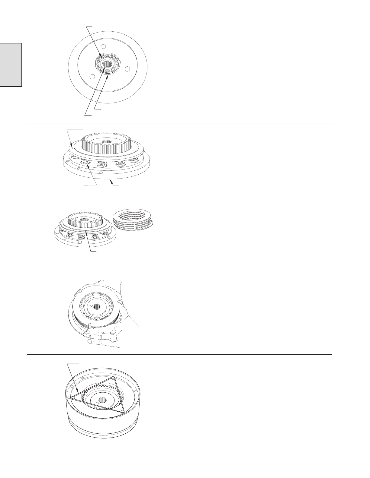
5. Install the retainer ring (25) that holds the inner race in
position.
(Dwg. MHP0839)
(Dwg. MHP0847)
Pressure Plate
Spring
in pocket Support Plate
Alternate the seperator
and friction plates
6. Position the support plate with the spring pockets facing up.
Place the springs (21) into the pockets, and rest the pressure
plate (12) on top of the springs with the stepped side of the
pressure plate facing away from the springs.
7. Coat the friction (13) and separator plates (14) with oil.
Starting with one of the steel separator plates, alternately place
the separator and friction plates over the outer race.
8. Use the loose dowel pins (8) to help line up the three notches
on the steel separator plates.
(Dwg. MHP0849)
Elastic Band
(Dwg. MHP1120)
9. Place a new gasket (19) on the mating surface of the support
plate.
10. Set the disc brake housing (7) on its side, and slip the three
dowel pins (8) through the holes provided. Wrap an elastic
band around the dowel pins (on the shallow side of the disc
brake housing) to hold them in position.
11. Set the disc brake housing down over the plates, shallow side
up. Ensure the bolt holes are aligned.
8
Page 9
(Dwg. MHP0837)
Capscrews
air line connection
Oil Drain Plug
The dowel pin in the back of the
support plate must be between the
oil level plug and the oil drain
plug.
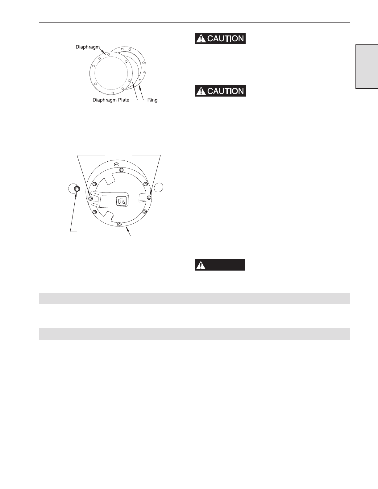
12. Remove the elastic band and install ring (5), followed by
diaphragm plate (6), diaphragm (10), and cover plate (4).
Ensure the diaphragm plate is
positioned with the radius toward
the diaphragm. The radius must be
smooth and polished.
13. Insert two capscrews (2) in the holes lined up with the air inlet,
and alternately tighten them one turn at a time until the
assembly is snug.
14. Ensure the brake shaft (34) is positioned in the winch with the
shouldered end toward the brake. Install a new gasket, and
slide the brake assembly into place over the shaft.
15. Line the brake assembly up so that the dowel pin in the upright
engages the hole in the back of the support plate.
16. Install the remaining six capscrews (finger tight). Loosen the
two capscrews that hold the brake assembly together, and then
evenly tighten all eight capscrews. Using a crossing pattern,
torque the capscrews to 25 Nm (18 ft. lbs).
17. Reinstall the air fitting and air line, and refill the disc brake
with oil until the oil runs out of the oil level plug hole. Refer to
“LUBRICATION” section in the FA5A Winch Parts,
Operation and Maintenance Manual MHD56087 for suitable
oils. To avoid overfilling the disc brake, wait until oil stops
flowing out of the oil level hole before replacing the plug.
Section 1
(Dwg. MHP1077)
Adjusting the Disc Brake
Testing the Disc Brake
WARNING
1. No adjustments are required.
1. Ensure there is no load on the winch.
2. Set the air pressure to 6.3 bar (90 psig) static (while the air
motor is not running).
3. Disconnect the air line from the disc brake, and plug the air
line to prevent the loss of air pressure. (This will keep the disc
brake engaged while the winch is paying out.)
4. Move the winch control valve handle or operate the pendant
control in the payout direction. The winch drum should not
turn. If it does turn, refer to the “TROUBLESHOOTING”
section.
After performing any maintenance
on the winch, test winch before
returning it to service.
9
Page 10
Section 1
DISC BRAKE PARTS DRAWING
One-Way Clutch Detail
(Dwg. MHP0667)
(Dwg. MHP0630)
10
Page 11
ITEM
NO.
DESCRIPTION
OF PART
TOTAL
QTY.
PART NO.
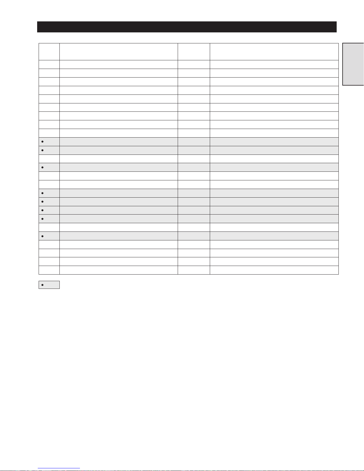
--- Disc Brake Assembly* 1 24140
1 Plug 2 71069009
2 Capscrew 8 71264717
3 Vent (25 psi) 1 71271175
4 Cover 1 23605
5 Ring 1 22028
6 Diaphragm Plate 1 22027
7 Housing 1 22026
8 Dowel Pin 3 71126882
10 Diaphragm 1 22031
11 One-way Clutch 1 71044853
12 Pressure Plate 1 24137
13 Friction Plate 5 71126874
14 Separator Plate 6 22033
15 Spacer 2 19007
16 Inner Race 1 24038
17 Outer Race 1 22032
19 Gasket 2 71262257
21 Spring 12 71053730
22 Support Plate 1 24138
23 Bearing 1 50449
24 Retainer Ring 1 54375
25 Retainer Ring 1 71053748
27 Dowel Pin 1 71126759
34 Brake Shaft 1 24039
Recommended Spare
* Disc Brake Assembly includes items 1 through 34
DISC BRAKE PARTS LIST
Section 1
11
Page 12
MANUAL BAND BRAKE ASSEMBLY - GENERAL INFORMATION
Description
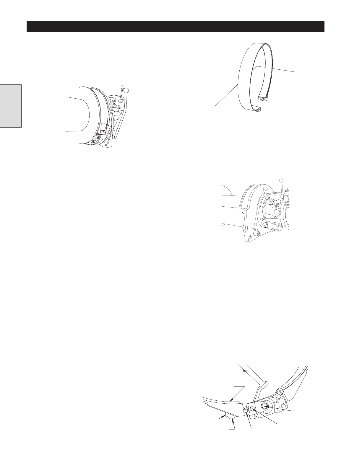
The optional manual band brake for the FA5A winch is located
on the end of the winch drum next to the air motor. It consists of
a friction material lined steel band (the brake band) that
encircles and grips a brake surface on the winch drum, and a
manually operated engagement and release mechanism.
Section 2
(Dwg. MHP1043)
Operation
The winch operator can engage the brake band at any time,
whether the winch drum is turning in the haul-in direction,
stationary, or turning in the payout direction. Moving the brake
handle towards the winch turns an eccentric shaft which
tensions the brake band, causing it to grip the brake surface and
prevent the winch drum from turning. The handle will “overcenter” and remain in the engaged position until released by the
operator.
To release the manual brake, the operator must pull the handle
away from the winch to the disengaged position allowing the
winch drum to rotate freely. The winch operator needs only to
apply light pressure (about 2.3 to 4.5 kg [5 to 10 pounds]) at the
brake handle to engage the brake and prevent the winch drum
from rotating, and only about 13.6 kg (30 pounds) to move the
handle “over-center” in order to lock the brake in the engaged
position.
The band brake is designed to work more efficiently in the
payout direction than in the haul in direction. Therefore, if the
brake is applied when hauling in, it may not completely stop the
winch drum from turning.
Components
The band brake has two main assemblies. The first assembly
consists of a friction material lined steel band that encircles and
grips the brake surface at one end of the winch drum. The
second assembly is the handle and eccentric assembly that
tensions and releases the band when the winch operator moves
the brake handle.
(Dwg. MHP1030)
Handle and eccentric assembly
Refer to Dwg. MHP1037
The brake handle has a splined end that engages an eccentric
shaft passing through bearings in an brake bracket which bolts
to the winch upright. There are two needle bearings pressed
into the brake bracket, and are protected from contamination
by ‘O’ rings that act as dirt exclusion seals.
(Dwg. MHP1037)
A cam plate pivots on the end of the eccentric shaft, and this
plate is connected to the free end of the brake band by an
adjustment bolt. The cam plate contains a self lubricating
composite bearing (the sleeve bearing) that allows the cam
plate to pivot freely when the brake is being operated. The
adjustment bolt passes through a pivot bar, and is retained in
the pivot bar by a jam nut that is permanently secured to the
bolt. Turning the jamnut (using an open end wrench) adjusts
the band brake. A locking capscrew acting on a soft bronze
locking pellet prevents the adjustment bolt from turning once
the brake is properly adjusted.
The locking pellet prevents the locking capscrew from
damaging the adjustment bolt when the locking capscrew is
tightened. The pivot bar allows the adjustment bolt to pivot
slightly as the brake is tensioned and released.
Function
Brake band
The brake band is composed of a flat steel strip formed into a
circular shape and lined inside with a friction material. Capscrews
threaded through brackets welded to the brake band attach one end
of the band to the eccentric assembly and fasten the other end to an
brake bracket secured to the winch upright.
Adjustment
Bolt
(Dwg. MHP1035)
12
Handle
Brake Band
Friction Lining
Pivot Bar
Eccentric
Shaft
Locking Capscrew
Jam Nut
Page 13
MANUAL BAND BRAKE TROUBLESHOOTING
This section provides basic troubleshooting information. Specific
causes to problems are best identified by thorough inspections
performed by personnel instructed in safety, operation and
maintenance of this equipment. The chart below provides a brief
guide to common manual brake symptoms, probable causes and
remedies.
ITEM
NO.
DESCRIPTION
OF PART
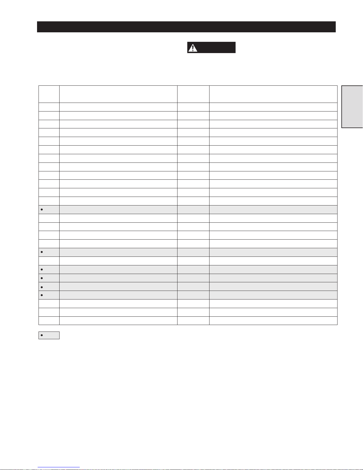
--- Brake Assembly 1 21890
101 Capscrew 3 71264808
102 Hardened Washers 3 21899
103 Spacer Tube 3 21891
104 Band Assembly 1 24367
105 Spacer 1 23029
106 Brake Bracket 1 21884
107 Capscrew 2 71264832
112 Capscrew 2 71264824
117 Jam Nut 2 71264790
119 Pivot Bar 1 23755
120 Capscrew 1 71288039
129 Locking Pellet 1 23737
130 Capscrew 2 52160
131 Cam Plate 1 21893
132 Retainer Ring 1 71145122
133 Washer 1 71137905
134 Sleeve Bearing 1 23749
135 Eccentric Shaft 1 21895
137 “O” Ring 1 71138648
138 Bearing 1 71138663
140 Bearing 1 71138671
141 “O” Ring 1 71138697
142 Brake Handle 1 21898
143 Washer 2 71266449
145 Handle Ball 1 71144273
WARNING
from the winch drum. Failure to remove the wire rope
before working on the winch can cause mechanical
damage and/or injury.
TOTAL
QTY.
Before troubleshooting the
band brake, remove the wire rope
PART NO.
Section 2
Recommended Spare
13
Page 14
MANUAL BAND BRAKE MAINTENANCE
Read these instructions completely before working on the manual band brake.
WARNING
band brake while there is a load on the winch can
result in mechanical damage and/or injury.
Before working on the band
brake, make sure the wire
rope is slack. Releasing the
Manual Band Brake Removal and Disassembly
Section 2
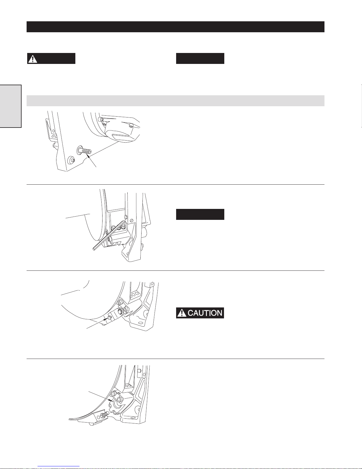
Remove the Brake Handle.
(Dwg. MHP1044)
Remove the three
Capscrews holding
the BrakeBand to
the BrakeBracket.
NOTICE
inches]. Be sure to support the winch securely so that it
cannot move while it is being serviced.
1. Remove the sideframe closest to the brake assembly by taking
out the four capscrews that fasten the sideframe to the uprights.
This will allow easy access to the band brake assembly.
2. Move the brake handle to the brake release position.
3. Remove the capscrew (130) and washers (143) that hold the
band brake handle to the eccentric shaft (135), and pull the
handle off the shaft.
4. Remove the three capscrews (101) that anchor the stationary
end of the brake band to the brake bracket (106).
NOTICE
Service is most easily done with
the motor end of the winch
blocked up approximately 10 cm [4
Make sure to remove and set aside
the three tubular steel spacers
(103) and the rubber spacer (105).
(Dwg. MHP1036)
Loosen the Locking
Capscrew before removing
the Adjustment Bolt.
(Dwg. MHP1041)
Remove the
Eccentric Shaft.
(Dwg. MHP1034)
5. Loosen the locking capscrew (130) and then unscrew the
adjustment bolt (120) from the cam plate (131). (Note: The
locking pellet (129) may fall out if the adjustment bolt is
removed. Retain it for reuse.)
The adjustment bolt is a specially
treated, high strength fastener
permanently attached to the jam
nut. Do not remove the adjustment bolt from the end of
the band brake unless the threads have been damaged,
or if the brake band itself is being replaced.
6. Push the splined end of the eccentric shaft (135) towards the
drum and remove it from the brake bracket (106).
14
Page 15
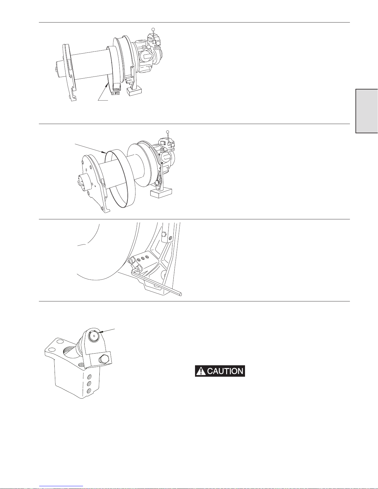
(Dwg. MHP1033)
7. Gently spread the ends of the brake band apart and slide it off
the brake drum and onto the winch drum.
Section 2
Move the Brake Band onto the
Winch Drum barrel diameter.
Remove theBrake Band
from the Winch Drumbarrel
diameter .
(Dwg. MHP1045)
Remove the Brake Bracket
from the Winch Upright.
(Dwg. MHP1042)
Removethe Retainer Ring
and Washer to remove
the Cam Plate from the
Eccentric Shaft and take
off the Sleeve Bearing.
8. Gently spread the ends of the brake band apart far enough to
clear the winch drum barrel diameter and take it off the drum.
9. Using a 10 mm allen wrench, loosen and remove the two long
and two short capscrews (107 and 112) that fasten the brake
bracket (106) to the winch upright.
10. If needed, the ‘O’ rings and bearings can be removed from the
brake bracket. The ‘O’ rings are easily removed with a blunt
scribe or a screwdriver, and the small needle bearing (140) can
easily be removed by pressing it out. Removal of the larger
needle bearing (138) is only required if the bearing housing is
cracked or chipped or if the rollers are damaged. Removal in
this case can be accomplished using a punch, driven against the
bearing outer race.
(Dwg. MHP1040)
This may shatter the race and
cause pieces to scatter. Be sure to
wear safety glasses.
11. Remove the retainer ring (132) that holds the cam plate to the
eccentric shaft, and remove the washer (133), cam plate (131),
and sleeve bearing (134). This completes the disassembly of
the manual band brake.
15
Page 16
Inspection
1. Check the sleeve bearing allows free movement of the cam
plate. Replace if worn oval by more than 0.76 mm (0.03
inch).
2. Inspect the eccentric shaft bearing surfaces for galling and
flat spots.
3. Make sure the two bearings in the brake bracket allow the
eccentric shaft to move smoothly and easily. Replace the
bearings if any of the needles are damaged or if the outer
shells are cracked or chipped.
4. Examine the adjustment bolt threads and the locking pellet
for any damage. Replace them if the adjustment bolt is bent
or the threads are damaged, or if the pellet is tight in the
Section 2
threaded locking screw hole.
5. Make sure that the rubber spacer between the brake band
and the brake bracket is still pliable and has not hardened
or cracked.
Manual Band Brake Assembly and Installation
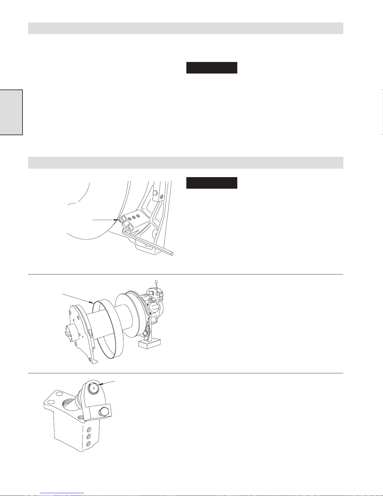
Install the Brake Bracket
onto the Winch Upright.
(Dwg. MHP1094)
6. Replace the brake band if the friction surface measures less
than 1.5 mm (1/16 inch) thick anywhere on the band.
NOTICE
7. Check the tubular spacers for signs of collapsing. If any of
them are buckling or collapsing, replace them as a set. They
should measure 28.3 to 28.8 mm (1.115 to 1.135 inches).
8. Check for any signs of wear on the hardened flat washers that
retain the tubular spacers. If they are wearing, replace them as
a set.
9. Inspect the ‘O’ rings (the dirt exclusion seals) for damage.
Replace if necessary.
NOTICE
mately 10 cm [4 inches]. Be sure to support the winch
securely so that it cannot move while it is being serviced.
1. If the needle bearings (138 and 140) were removed, press them
back into place. Lubricate them by packing with a good quality
EP grease, and install and lubricate the ‘O’ ring dirt exclusion
seals with the same grease.
2. Using the two long (107) and two short (112) capscrews,
fasten the brake bracket (106) to the winch uprights. Torque
the capscrews to 45-50 Nm (33-36 ft. lbs.)
Do not wash the brake band in
cleaning solvent. Wipe clean, or
if needed use a commercially
available brake cleaner.
Band brake installation is most
easily done with the motor end of
the winch blocked up approxi-
Install the Brake Band
onto the Winch Drum barrel
diameter.
(Dwg. MHP1095)
(Dwg. MHP1092)
Install the Sleeve
Bearing, Cam Plate,
Washer and Retainer
Ring on the
Eccentric Shaft.
3. Gently spread the ends of the brake band (104) apart and slip
the band over the winch drum barrel diameter.
4. Gently spread the ends of the brake band, and slip it over the
flange and onto the brake surface.
5. Lubricate the sleeve bearing (134) with EP grease, and install
on the eccentric shaft (135) followed by the cam plate (131),
the washer (133), and the retainer ring (132).
6. Insert the eccentric shaft into the brake bracket .
16
Page 17
Tubular
t
Spacer
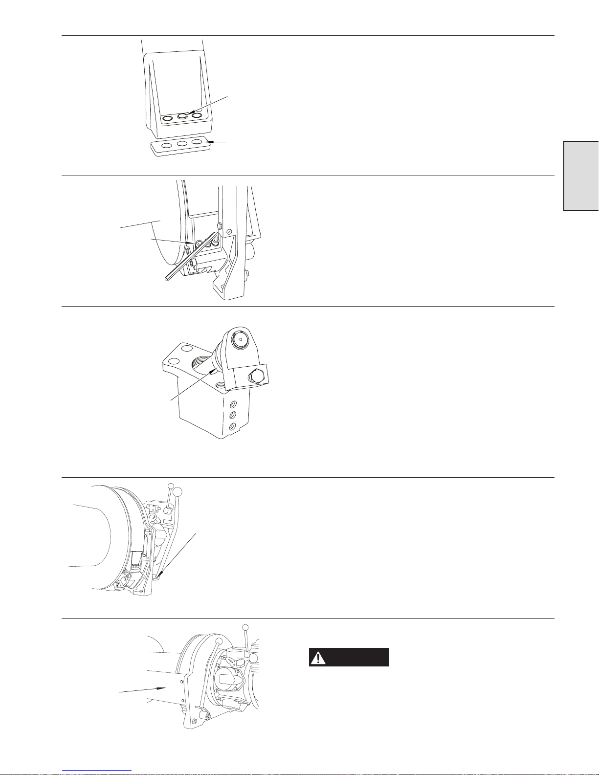
7. Place the three anchor capscrews (101) through the washers
(102), tubular spacers (103), the brake band (104) and the
rubber spacer (105).
(Dwg. MHP0986)
Install Capscrews
and torque.
(Dwg. MHP1091)
Place the post near
the 6 o’clockposition
(Dwg. MHP1093)
Rubber
Spacer
Section 2
8. Fasten the end of the brake band to the brake bracket and
torque the capscrews to 45-50 Nm (33-36 ft. lbs).
9. Position the eccentric shaft so that the post on the eccentric shaft
is near the “6:00 o’clock” position. If it is necessary to replace the
adjustment bolt, procure the proper replacement bolt from an
Ingersoll-Rand distributor. Remove the protective coating from
the threads for a distance of 9.5 mm (3/8 inch) from the shank of
the capscrew. Insert the new capscrew through the pivot bar and
the brake bracket on the brake band. Apply several drops of
Loctite® 242 threadlocking compound onto the bare threads near
the shank of the capscrew. Install and tighten a jam nut to hold
the adjustment bolt in position. The adjustment bolt should turn
freely. Thread the adjustment bolt at least 10 mm (3/8 inch) into
the cam plate. This ensures that the locking pellet will contact the
adjustment bolt and hold it in place. Insert the locking pellet
inside the threaded hole in the side of the cam plate, and hand
tighten the locking capscrew into position.
Rotate the Eccentric Shaft
by hand as far as possible
in direction of engagemen
and install Brake Handle.
(Dwg. MHP1090)
Install Sideframe
before adjusting
Brake Band.
(Dwg. MHP1089)
10. By hand, rotate the eccentric shaft and cam plate in the
engaged direction as far as possible. Then, install the brake
handle in the released position. The handle should move easily
in both directions, and should not fully engage the brake
before it is adjusted. If needed, reposition the brake handle
before adjusting the brake.
11. Install the sideframe, and then adjust the band brake.
WARNING
Always adjust and test the band
brake after completing repairs or
adjustments. Failure to adjust and
test the band brake could lead to mechanical damage
and/or injury.
17
Page 18

Adjusting the Manual Band Brake
1. Place the band brake handle in a completely released
position. Take up some of the slack in the brake band by
turning the adjustment bolt, and then tighten the locking
capscrew to prevent the adjustment bolt from moving.
2. Move the control handle towards the engaged position. The
handle should encounter growing resistance starting at
about the last third of its travel. The resistance should not
be enough to stop the handle from going “over-center” at
the end of its travel. Make sure the handle does not contact
the air motor adapter before it goes fully over-center. For
maximum load holding capacity, the handle should just
“over-center” before it touches the motor adapter. If it
Section 2
“over-centers” too soon, the brake holding capacity will be
diminished. If it does over-center too soon, reposition it on
the splined eccentric shaft and readjust the brake.
Testing the Manual Band Brake
1. Remove any load from the winch, or if possible remove the
wire rope. If there is wire rope on the winch, this test may
cause it to unspool.
2. Set the inlet air pressure to 6.3 bar (90 psig) static (while
the air motor is not running).
3. If the winch is equipped with an automatic disc or band
brake, it must be disengaged before testing the band brake.
Disconnect the air line from the automatic disc or band
brake, and plug it to prevent loss of air pressure. Apply and
hold air pressure from an external source 3.5 to 6.3 bar (50
to 90 psig) directly to the air line fitting on the automatic
disc or band brake while testing the manual band brake.
3. The force needed to move the handle “over-center” should be
about 13.5 kg (30 lbs). If the handle cannot go “over-center,”
or if there is excessive resistance, reduce the tension by turning
the adjustment bolt in the counterclockwise direction. There
must be slack in the band brake when the handle is in the
released position. Always test the band brake before use.
4. Move the brake handle towards the winch until it goes fully
“over-center.”
5. Move the winch control valve handle or operate the pendant
control in the payout direction. The winch drum should not
turn. If it does turn, review the information on troubleshooting
the manual band brake.
18
Page 19

SERVICE NOTES
Section 2
19
Page 20
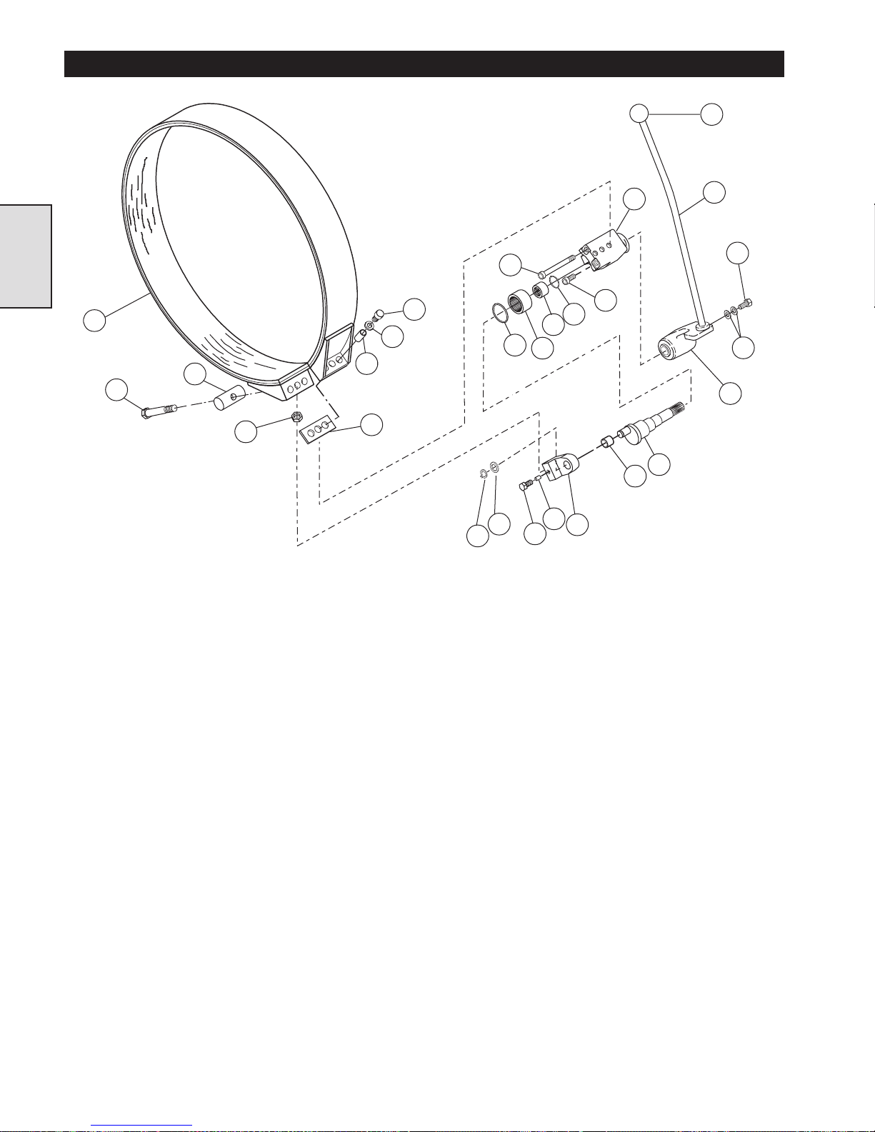
MANUAL BAND BRAKE PARTS DRAWING
145
Section 2
104
(Dwg. MHP1079)
120
119
117
103
105
102
101
132
133
107
137
130
138
140
129
141
131
112
106
134
142
130
143
142
135
20
Page 21
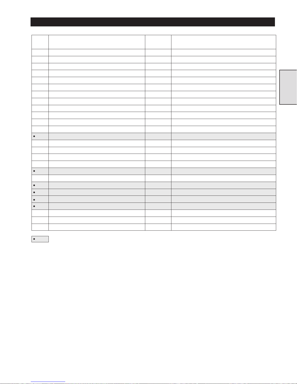
MANUAL BAND BRAKE PARTS LIST
ITEM
NO.
DESCRIPTION
OF PART
--- Brake Assembly 1 21890
101 Capscrew 3 71264808
102 Hardened Washers 3 21899
103 Spacer Tube 3 21891
104 Band Assembly 1 24367
105 Spacer 1 23029
106 Brake Bracket 1 21884
107 Capscrew 2 71264832
112 Capscrew 2 71264824
117 Jam Nut 2 71264790
119 Pivot Bar 1 23755
120 Capscrew 1 71288039
129 Locking Pellet 1 23737
130 Capscrew 2 52160
131 Cam Plate 1 21893
132 Retainer Ring 1 71145122
133 Washer 1 71137905
134 Sleeve Bearing 1 23749
135 Eccentric Shaft 1 21895
137 “O” Ring 1 71138648
138 Bearing 1 71138663
140 Bearing 1 71138671
141 “O” Ring 1 71138697
142 Brake Handle 1 21898
143 Washer 2 71266449
145 Handle Ball 1 71144273
TOTAL
QTY.
PART NO.
Section 2
Recommended Spare
21
Page 22
AUTOMATIC BAND BRAKE - GENERAL INFORMATION
Description
The optional automatic band brake for the FA5A winch is located
on the end of the winch drum next to the air motor. It consists of a
friction material lined steel band (the brake band) that encircles
and grips a brake surface on the winch drum, and a spring loaded
pneumatic release assembly.
(Dwg. MHP0983)
Operation
Section 3
The friction material lined steel band remains tensioned, gripping
the brake surface until the winch control valve or pendant control
is operated to haul-in or payout a load. When the winch is hauling
in or paying out a load, air pressure applied to a cylinder assembly
releases the band brake and allows the winch drum to rotate
freely. When the operator returns the winch control valve handle
to the neutral position or stops operating the pendant control, the
air pressure is shut off and spring pressure tensions the brake,
preventing the winch drum from rotating.
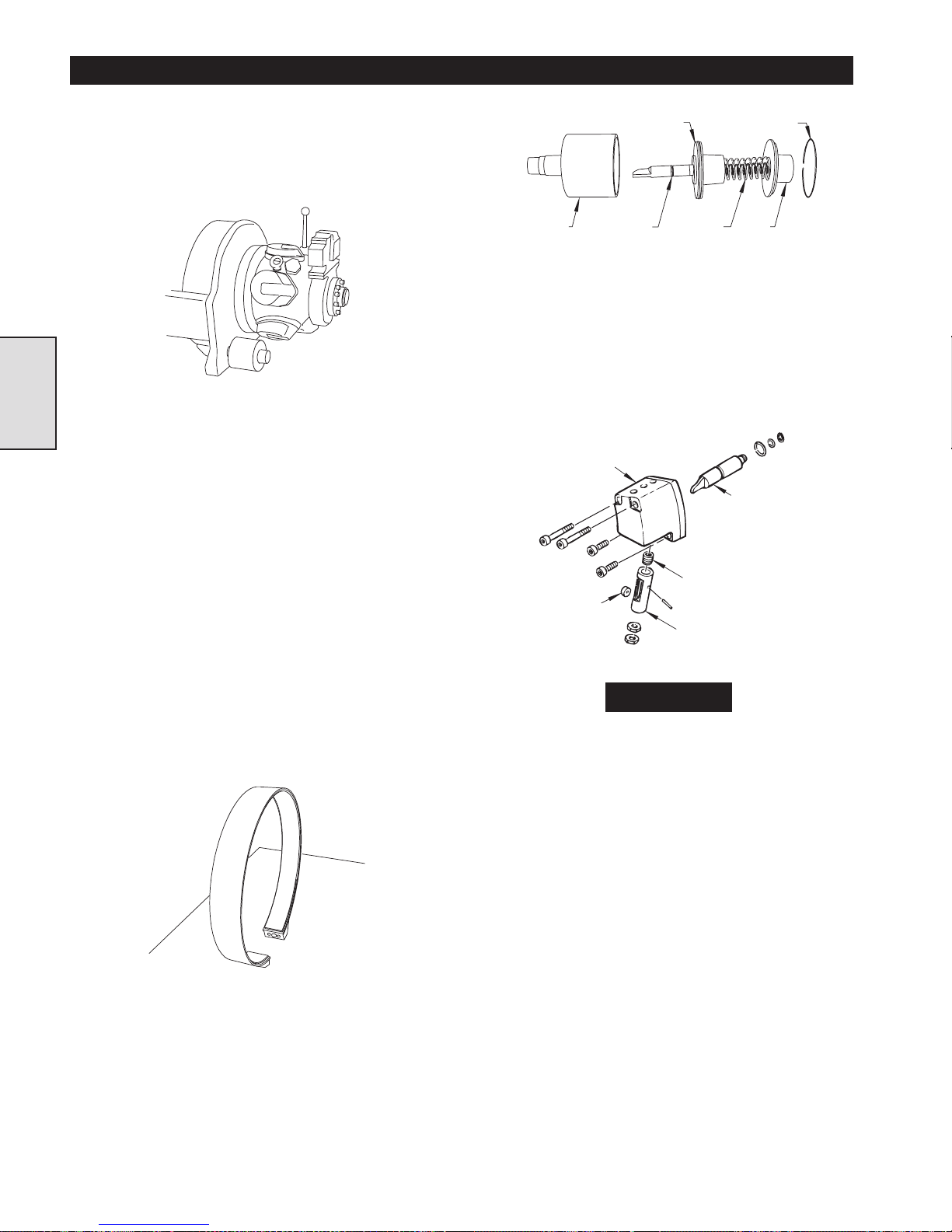
Components
The automatic band brake consists of two main assemblies. The
first consists of a brake band that encircles a brake surface on
one end of the winch drum. The second is a spring loaded
pneumatic release assembly that is activated by air pressure from
the winch control valve or pendant control.
Piston
Cylinder Cylinder Rod
(Dwg. MHP0984)
(B) Brake bracket and plunger assembly
The brake bracket and plunger assembly is bolted to the drum
side of the winch upright (next to the motor). Four capscrews
fasten the brake bracket to the upright. Three more capscrews
fasten one end of the brake band to the brake bracket. Inside the
brake bracket is a plunger that is attached to the other end of the
brake band by an adjustment bolt. The adjustment bolt runs
through a pivot bar on the band and threads into the plunger. The
pivot bar allows the adjustment bolt to pivot slightly as the brake
is tensioned and released.
Brake Bracket
Roller
(Dwg. MHP1081)
Springs Cover
Spring
Plunger
Retainer
Cylinder Rod
Brake band
The brake band is composed of a flat steel strip formed into a
circular shape and lined inside with a friction material. Capscrews
threaded through welded brackets anchor one end of the brake
band to the winch and fasten the other end of the brake band to
the pneumatic release assembly.
Dwg. MHP1030
Pneumatic release assembly
The pneumatic release assembly is composed of two parts: (A)
the cylinder assembly, and (B) the brake bracket and plunger
assembly.
(A) Cylinder assembly
The cylinder assembly consists of a cylinder that houses a
cylinder rod, a piston, a nested pair of springs, and a cover that
is secured to the cylinder by a retainer ring. The cylinder
assembly threads through the side frame of the winch into the
brake bracket and plunger assembly.
NOTICE
Additional important parts that allow the band brake
to function properly are the dump-valve and the
orifice. These parts thread into the side of the cylinder
assembly, and release air pressure on the brake at a
controlled rate allowing the band brake to engage
promptly and without hesitation.
Function
The automatic band brake is spring actuated so that it is always
tensioned unless the winch operator moves the winch control
valve handle or operates the pendant control to haul-in or payout
a load. Springs inside the cylinder assembly push on a piston that
is connected to the cylinder rod. The cam shaped end of the
cylinder rod engages a plunger inside the band bracket. The
plunger is attached to the brake band by an adjustment bolt.
While the springs press on the piston, the cylinder rod moves the
plunger, pulls on the adjustment bolt, and tensions the brake.
When the operator moves the winch control valve or operates the
pendant control, some air pressure is diverted to the brake
cylinder. The air pressure acts on the piston to counteract the
spring pressure and retract the cylinder rod. When the cylinder
rod retracts, it allows the plunger to move the brake band into the
released position. When the operator returns the winch control
valve handle to neutral or stops actuating the pendant control, air
pressure to the brake is shut off, the dump valve releases the air
pressure from the cylinder, and the spring pressure pushes on the
piston causing the band brake to engage.
22
Page 23
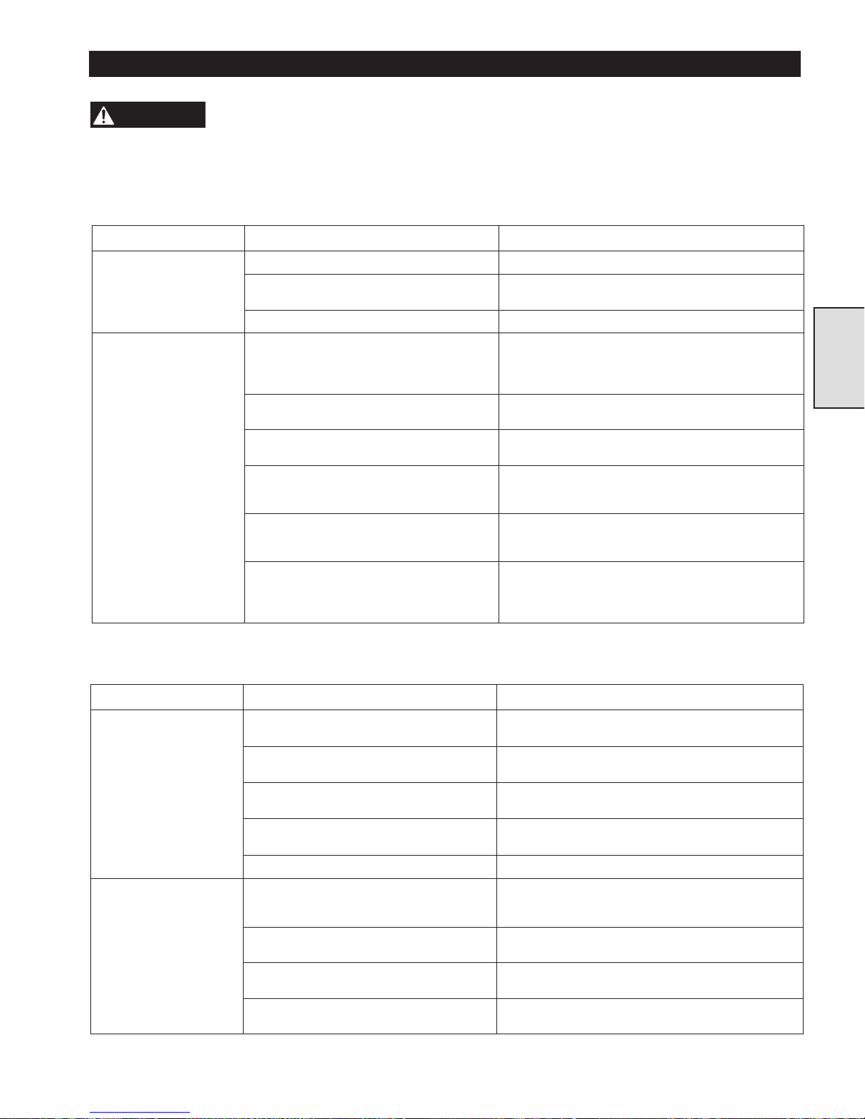
AUTOMATIC BAND BRAKE TROUBLESHOOTING
Symptom Cause Remedy
The brake does not
release.
The air line is not connected to the brake. Make sure the air line is connected to the brake.
The air line is blocked, pinched, or torn. Make sure that the air line is not blocked, torn or
pinched. Replace the air line if necessary.
The brake is not adjusted properly. Adjust the brake.
The band brake does not
hold the load.
The brake band (104) has worn past safe
limits.
Adjust the brake band (refer to proper section). Replace
the band if it measures less than 1.5 mm (1/16 inch)
thick anywhere on the band lining, or if it can no longer
be adjusted.
The adjustment bolt (120) is not locked in
position.
Check the adjustment bolt lock nuts, and tighten them if
needed.
The three anchor capscrews (101) are loose. Inspect the anchor capscrews. If necessary, torque them
to 45-50 Nm (33-36 ft lbs.)
The three tubular spacers (103) have collapsed
or are worn.
Inspect the tubular spacers. They should measure
between 28.3 and 28.8 mm (1.115 and 1.135 inches).
If they have collapsed or are worn, replace them.
The brake activation components in the winch
control valve are out of adjustment, or the
control handle is not returning to neutral.
Refer to the manual for instructions on troubleshooting
and adjusting the brake actuation components in the
winch control valve.
The orifice and dump valve assembly are not
relieving air pressure from the brake.
To check, operate the winch control valve handle or
pendant control, while feeling and listening for air
escaping from the dump valve. If no air is, detected,
replace the orifice and dump valve assembly.
Symptom Cause Remedy
The band brake does not
release.
Air is leaking past the piston (123) inside the
cylinder (121).
Replace the ‘O’ rings (109, 110, and 122) that prevent air
from leaking inside the cylinder.
The retainer ring (111) that fastens the cylinder
rod (108) to the piston (123) has failed.
Replace the retainer ring.
The cylinder rod (108) is sticking inside the
cylinder (121).
Make sure the cylinder rod slides smoothly inside the
cylinder.
The plunger (114) is sticking inside the brake
bracket (106).
Make sure the plunger slides smoothly inside the brake
bracket.
The spring (113) has collapsed or is bent. Replace the spring.
The band brake does not
hold the load.
The springs in the pneumatic release assembly
have collapsed.
Check the spring length. The springs (124) and (127)
should measure 203 mm (8.0 inches). If either spring
measures less than this dimension, replace.
The cylinder rod (108) is sticking in the
cylinder (121).
Make sure the cylinder rod is lubricated properly and
slides smoothly inside the cylinder.
The plunger (114) is sticking inside the brake
bracket (106).
Make sure that the plunger is lubricated properly and
slides smoothly inside the brake bracket.
The roller (116) or dowel pin (115) is worn or
broken.
Inspect the roller and dowel pin for wear. Replace if
necessary.
WARNING
Failure to remove the wire rope before working on the
winch can cause mechanical damage and/or injury.
Check the following before removing any brake components from the winch:
Before troubleshooting the
band brake, remove the wire
rope from the winch drum.
There are two ways that the band brake can cause problems:
1. It might not release
2. It might not hold the load
If one of the above problems is present check the following before
removing any brake components from the winch:
Section 3
If the air pressure is adequate and the brake is properly adjusted, remove the pneumatic release assembly from the winch and continue
troubleshooting.
23
Page 24
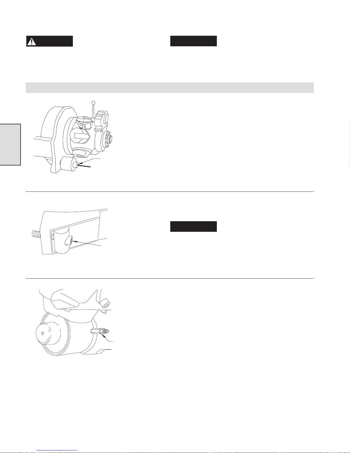
Read these instructions completely before working on the automatic band brake.
WARNING
wire rope has been removed. Working on the brake
while there is a load on the winch can cause
mechanical damage and/or injury.
Before working on the band
brake, make sure that the air
to the winch is shut off, and the
Automatic band brake maintenance
Section 3
(Dwg. MHP1096)
Release the Band Brake
by tightening the Nut on
the threaded rod.
NOTICE
in.). Be sure to support the winch securely so that it
cannot move while being serviced.
1. Remove the winch sideframe closest to the brake assembly by
taking out the four capscrewss fastening it to the corner bars
mounted to the uprights. This will allow easy access to the
band brake assembly.
2. Thread a piece of 3/8 NC threaded rod approximately 36 cm
(14 inches) long fully into the tapped hole in the cylinder rod
(inside the cylinder). Make sure the threaded rod is fully
tensioned. Slip a flat washer over the threaded rod, and then
thread a nut against the cover. Tighten the nut to disengage the
brake band.
3. While the brake band is in the released position, loosen the
adjustment bolt lock nut (117) and thread the adjustment bolt
(120) all the way out of the plunger (114).
Service is most easily done
with the motor end of the winch
blocked up approximately 10 cm (4
(Dwg. MHP0976)
(Dwg. MHP0980)
Thread the Adjustment
Bolt all the way out of
the Plunger.
Remove the Dump
Valve and Orifice
Assembly.
NOTICE
4. Remove the air line and remove the dump valve and orifice
assembly from the cylinder.
Do not remove the locknuts from
the adjustment bolt unless the bolt
is to be replaced.
24
Page 25
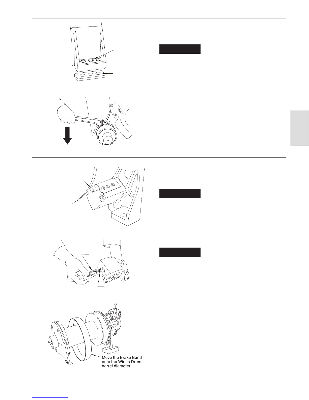
5. Remove the three capscrews (101) and washers (102) that
fasten the stationary end of the brake band to the brake bracket
(106).
(Dwg. MHP0986)
(Dwg. MHP0923)
Remove the Capscrews
holding the Brake Bracket
to the Winch Upright.
Tubular
Spacer
Rubber
Spacer
NOTICE
6. Using a cloth strap wrench, turn the cylinder assembly
counterclockwise to loosen and remove it from the winch.
7. Using a 10 mm allen wrench, loosen and remove the two long
and two short capscrews (107 and 112) that fasten the brake
bracket to the winch upright. Remove the brake bracket from
the side frame.
NOTICE
brake surface. The 3/8 inch allen wrench has enough
clearance to turn near the drum flange.
Make sure to remove and retain
the three tubular steel spacers
(103) and the rubber spacer (105).
A 3/8 inch allen wrench may be
needed to remove the two socket
head capscrews closest to the
Section 3
(Dwg. MHP0979)
(Dwg. MHP0977)
Plunger
Spring
8. Pull the plunger (114) out of the brake bracket.
NOTICE
9. Carefully spread apart the ends of the brake band and move it
off the brake surface and onto the winch drum barrel diameter.
10. Carefully spread the ends of the brake band apart far enough to
clear the winch drum barrel diameter, and pull the brake band
off the drum. Do not damage the threads of the adjustment bolt
by dragging the bolt over the winch drum.
Make sure to remove and retain
the small spring (113) that rests
behind the plunger.
(Dwg. MHP1097)
25
Page 26
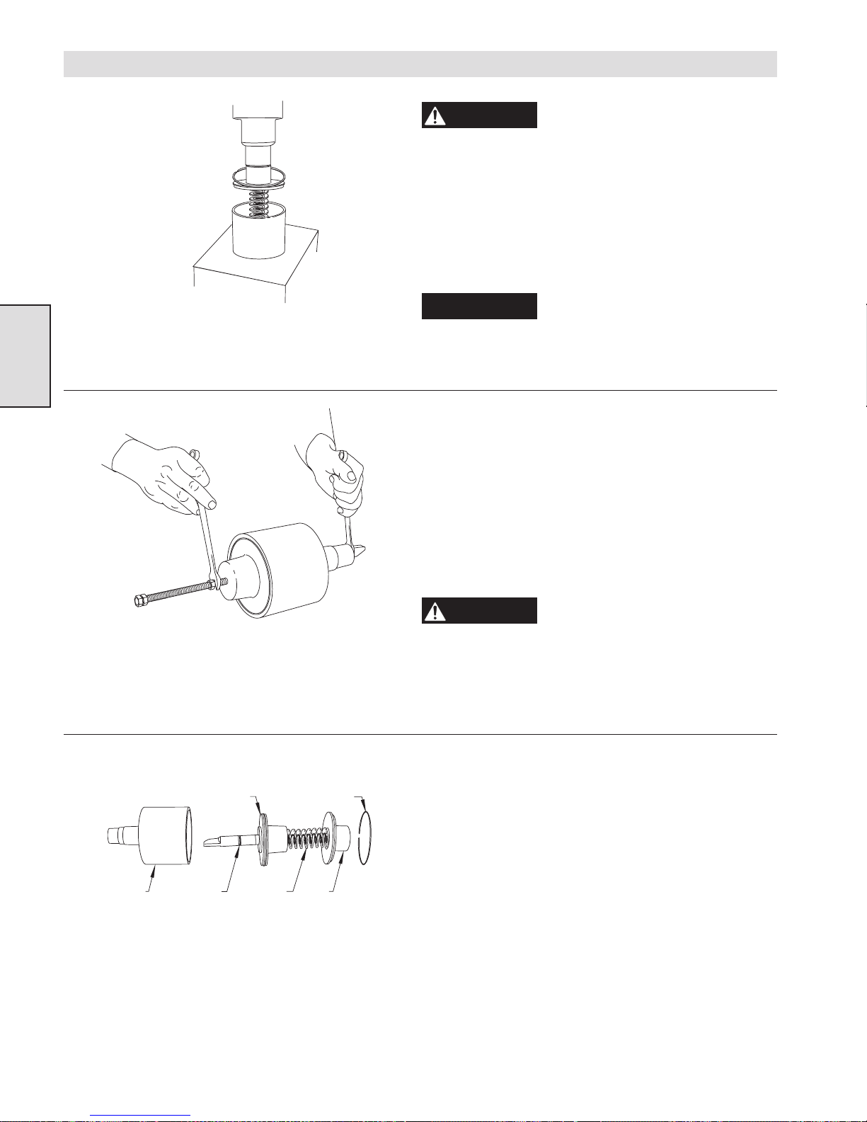
Cylinder Disassembly
(Dwg. MHP0924)
Section 3
Make sure press has
enough travel to allow
the springs to relax.
WARNING
at least 13 cm (5 inches) of travel, or use the threaded rod
method. Failure to exercise caution can cause mechanical damage and/or injury.
1. Place the cylinder assembly in a press, and press down on the
end cover (125). Using a screwdriver, locate the chamfer on
one end of the retainer ring (126), and remove the retainer ring.
Slowly release the press allowing the springs to push the cover
away from the cylinder.
NOTICE
(5 inches) when the springs extend to their uncompressed
state.
2. If a press is not readily available, there is an alternative method
of disassembling the cylinder assembly. Thread a piece of 3/8
NC threaded rod approximately 36 cm (14 inches) long, fully
into the tapped hole in the cylinder rod (inside the cylinder).
Make sure the threaded rod is fully engaged. Slip a flat washer
over the threaded rod, and then thread a nut all the way down
to the cover. Tighten the nut until the cover moves far enough
to uncover the retainer ring, and remove the ring. Use a 12 mm
(approximately 7/16 wrench) to prevent the cylinder rod from
turning, and remove the nut from the threaded rod. Spring
pressure will push the cover away from the cylinder, allowing
complete disassembly.
Use care when removing or
installing the end cover on the
cylinder. Use a sturdy press with
Before pressing down on the end
cover, operate the press so that it
can retract approximately 13 cm
(Dwg. MHP0981)
Cylinder Cylinder Rod
(Dwg. MHP0984)
Piston
Springs Cover
Retainer
WARNING
threaded rod is fully engaged in the cylinder rod. If the
threaded rod starts turning while removing the cover,
double nut it or otherwise hold it and prevent it from
threading out of the cylinder rod. Failure to exercise
caution can cause mechanical damage and/or injury.
3. Remove the springs (124 and 127) from the cylinder, and take
out the piston (123) and cylinder rod (108).
4. Remove the washer (128) inside the piston, take off the
retainer ring that holds the cylinder rod to the piston, and
remove the cylinder rod. This completes the disassembly of the
band brake and cylinder assembly.
Use care when removing or
installing the end cover on the
cylinder. Make sure that the
26
Page 27

Inspection
1. Examine the ‘O’ rings (109, 110, and 122) on the piston
and cylinder rod for signs of cracking or wear. If any of the
‘O’ rings are cracked or worn, replace them.
2. Make sure the cylinder rod (108) moves easily and
smoothly inside the cylinder (121), and make sure the
plunger (114) moves easily and smoothly inside the brake
bracket (106). If the cylinder rod or the plunger sticks or
hesitates, clean and polish (or replace) as necessary.
3. Inspect the roller (116) for wear on the inner and outer
surfaces, and the cylinder rod (108) for wear on the camshaped end. Replace both if any wear is found.
4. Check the pin (115) for wear. Replace the pin and the roller
(116) as needed.
5. Examine the springs (124 and 127). They should measure
at least 203 mm (8.0 inches) long. Replace them if they
have collapsed or become bent.
6. Ensure that the spring (113) has not collapsed or become bent.
It should measure at least 203 mm (8.0 inches) long. Replace it
if it has collapsed or become bent.
7. Check the tubular spacers for signs of collapsing. If any of
them are buckling or collapsing, replace them as a set. They
should measure 28.3 to 28.8 mm (1.115 to 1.135 inches)
8. Look for any signs of wear on the washers that retain the
tubular spacers. If they are wearing, replace them as a set.
9. Inspect the brake band lining for wear. It should be worn
evenly, without high or low spots anywhere around the brake
band. Replace the brake band if the friction surface measures
less than 1.5 mm (1/16 inch) thick anywhere on the band.
NOTICE
Do not wash the brake band in
cleaning solvent. Wipe clean if
needed. Use a commercially
available brake cleaner.
Section 3
27
Page 28
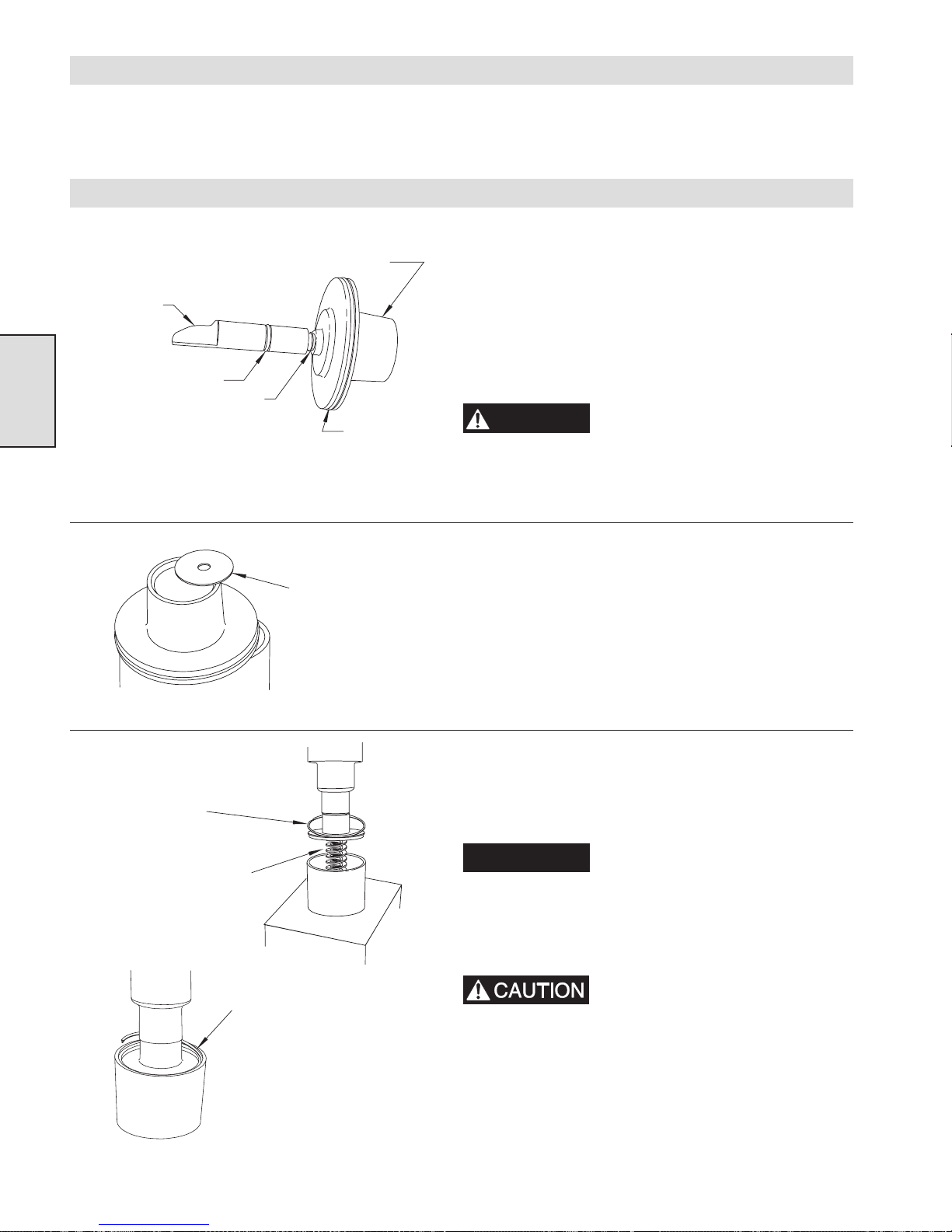
Automatic Band Brake Assembly and Installation
If assembling from new, or if the air motor and upright have been removed for service, the easiest way to assemble the automatic band
brake is to install everything except the cylinder assembly onto the upright and then mount the upright to the winch drum. The cylinder
assembly can be installed after the air motor is in place. The assembly and installation of the band brake follows these same basic steps.
Cylinder Assembly
1. Lubricate and install the two small ‘O’ rings (110 and 109)
onto the cylinder rod (108), and insert the cylinder rod into the
piston (123).
2. Install the retainer ring (111) that holds the cylinder rod on the
piston, and position the large ‘O’ ring (122) in the groove
around the piston.
3. Thoroughly coat the cylinder rod, the ‘O’ rings, and the inside
of the cylinder with Lubriplate Mo-Lith No. 2 (or equivalent)
grease.
WARNING
Use care when removing or
installing the end cover on the
cylinder. Use a sturdy press with
at least 13 cm (5 inches) of travel, or use the threaded rod
method. Failure to exercise caution can cause mechanical damage and/or injury.
Cylinder Rod
Section 3
(Dwg. MHP0982)
Retainer Ring inside Piston
Small ‘O’Ring
Small ‘O’Ring
Large ‘O’Ring
(Dwg. MHP0978)
Be sure to set Retainer Ring
on top of the Cover before
starting to press the Cover
into position.
Guide the Cover into
position while passing
it into the Cylinder.
(Dwg. MHP0924)
Be sure to place
Washer into Piston
before installing the
Piston into the
Cylinder.
Retainer Ring must be fully
seated into its groove.
4. Insert the piston and cylinder rod assembly into the cylinder,
and drop the washer (128) into the open end of the piston.
5. Set the cylinder (with the large open end upwards) in a sturdy
press. Place the two springs (124 and 127) on top of the washer
in the piston, set the large retainer ring (126) over the end
cover, and position the end cover over the springs. Carefully
press the cover into position on the cylinder.
NOTICE
The threaded rod method can be
used in the absence of a press.
Refer to cylinder disassembly
instructions.
6. Press the end cover (125) down until the retainer ring groove is
exposed, and install the retainer ring (126).
Make sure the retainer ring is fully
seated into its groove.
7. Remove the cylinder from the press. The cylinder assembly is
complete.
(Dwg. MHP0925)
28
Page 29
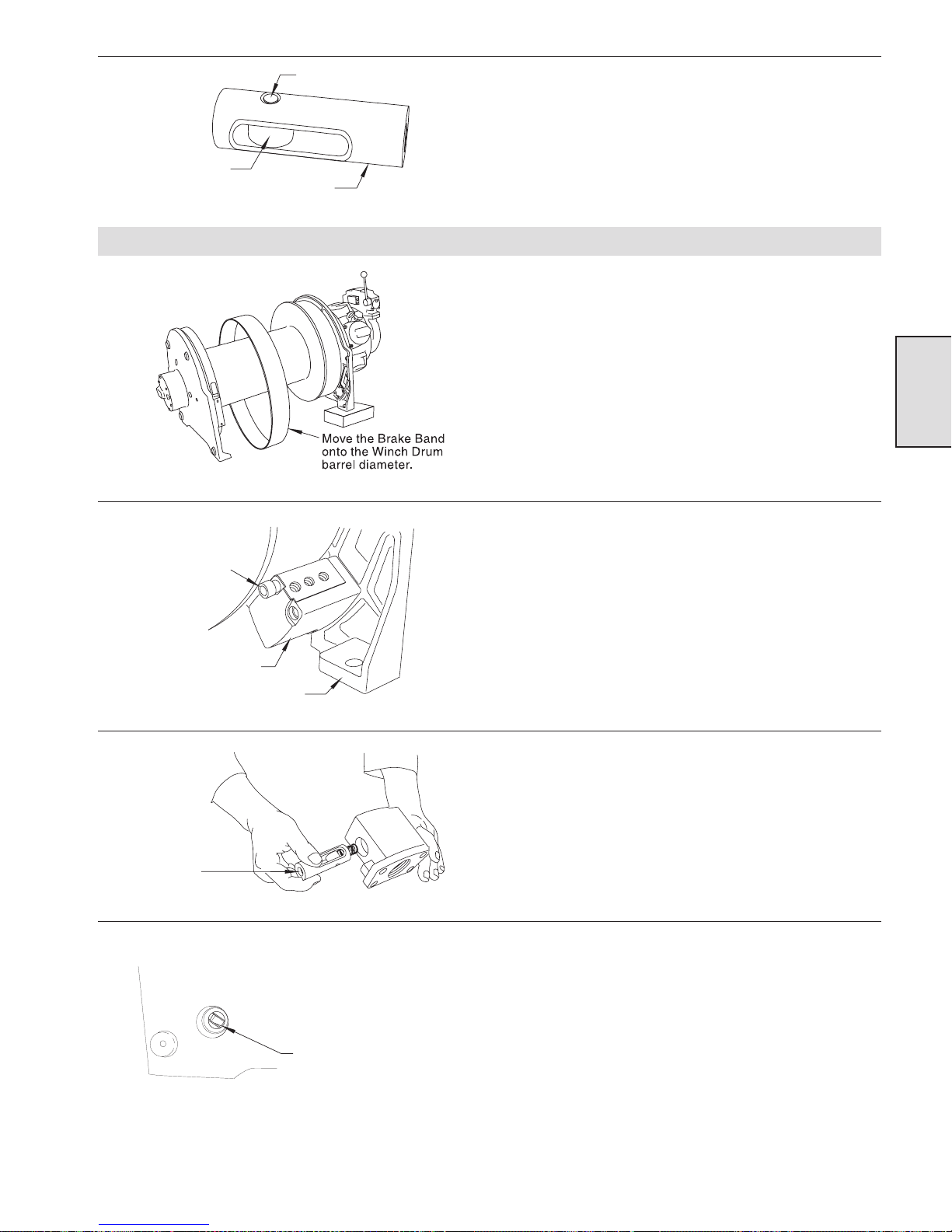
Pin
Roller
(Dwg. MHP0985)
Plunger Body
Automatic Band Brake Assembly and Installation
(Dwg. MHP1097)
Capscrew
8. To assemble the plunger, place the roller (116) inside the
plunger body (114), and then insert the pin (115). Before
installing the pin, thoroughly coat the pin, roller, and plunger
with Lubriplate Mo-Lith NO. 2 (or equivalent) grease.
1. Gently spread the ends of the brake band (104) apart, and slip
the band onto the winch drum barrel diameter.
Section 3
2. Using the two long (107) and two short (112) capscrews,
fasten the brake bracket (106) on to the winch upright. Torque
the capscrews to 45-50 Nm (33-36 ft. lbs).
3. Gently spread the ends of the brake band and slip it over the
flange and onto the brake surface.
Brake Bracket
(Dwg. MHP1099)
Threaded end of
Plunger must face
the open end of
the Bracket.
(Dwg. MHP1250)
Winch Upright
4. Place the small spring (113) in the end of the plunger, and slip
the plunger (114) into the brake bracket (106) bolted onto the
frame. Make sure that the threaded end of the plunger faces the
open end of the bracket. (Brake bracket pictured unmounted.)
5. Look through the hole in the upright and position the plunger
so that the slot in the plunger is aligned with the hole.
Make sure that the slot
in the Plunger is lined up
with the hole in the
Winch Upright.
(Dwg. MHP1032)
29
Page 30
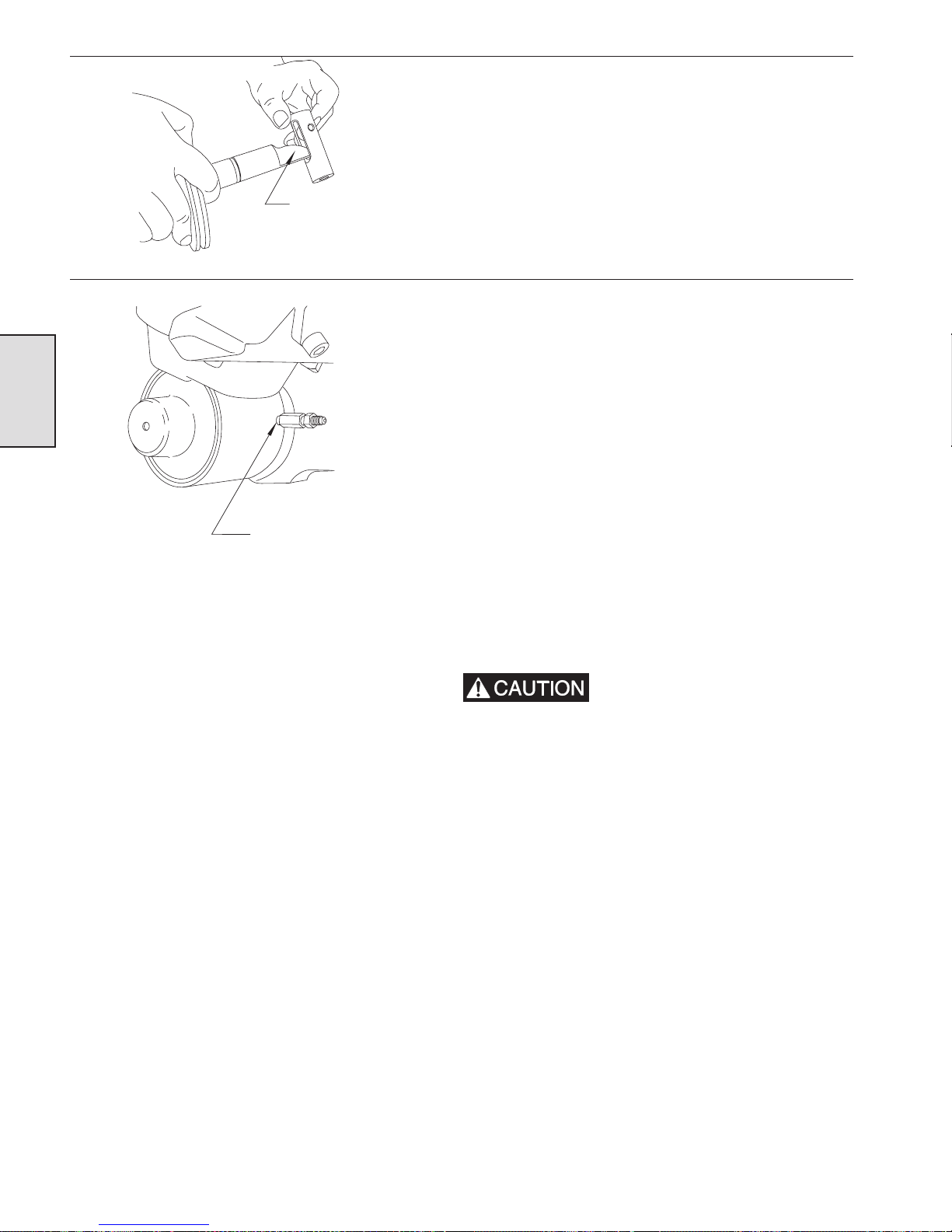
(Dwg. MHP1039)
Section 3
The Cylinder Rod must
be positioned with the
Cam shaped side against
the Roller.
Position threaded hole
horizontally and install
Dump Valve and Orifice
Assembly.
6. Position the cylinder rod (inside the plunger) with the cam
shaped side against the roller, and then screw the threaded end
of the cylinder assembly through the hole in the sideframe into
the bracket. (Cylinder rod and plunger are shown disassembled
for clarity.)
7. Thread the cylinder fully (until snug) into the side frame, and
then back off until the threaded hole in the side of the cylinder
is pointed towards the air motor and is positioned horizontally.
8. Install the dump valve and orifice assembly on the cylinder,
and connect the air line.
9. If the adjustment bolt lock nuts have been removed, apply
some thread-locking compound (Loctite® 680 or equivalent)
to the threads of the adjustment bolt close to the shank (near
the brake band). Thread one of the lock nuts onto the
adjustment bolt so that it holds the adjustment bolt on the
brake band with very little slack.
10. Loosely thread the adjustment bolt into the plunger.
11. Install the rubber spacer (105) between the brake band and the
brake bracket.
12. Fasten the stationary end of the brake band to the brake bracket
using the three capscrews (101), washers (102) and spacer
(103). Torque the capscrews to 45-50 Nm (33-36 ft lbs).
13. Fasten the corner bar to the winch upright, and torque the two
capscrews to 45-50 Nm (33-36 ft lbs). Install the sideframe and
torque the four capscrews to 72-78 Nm (52-57 ft lbs).
(Dwg. MHP1251)
Always adjust and test the band
brake after completing repairs or
adjustments. Failure to adjust and
test the band brake can lead to mechanical damage and/
or injury.
30
Page 31
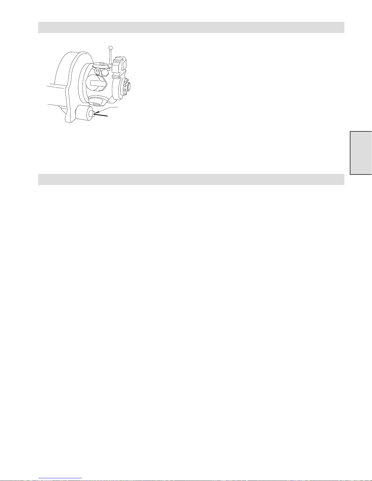
Adjusting the Automatic Band Brake
When Brakeis properly
adjusted, there should be
a gap of approximately
14 mm (9/16 in.) between
the Nut and the Cylinder
End Cover.
(Dwg. MHP0983)
Testing the Automatic Band Brake
1. Thread a piece of 3/8 NC rod all the way into the cylinder rod.
With the brake band slack and no air applied to the band brake,
push the end of the threaded rod to position the plunger all the
way inside the bracket. Turn a nut down the threaded rod until
it is even with or just touching the cylinder cover. Apply air
pressure to the band brake cylinder from an outside air source.
When air pressure is applied to the cylinder, the nut on the
threaded rod should move about 25 mm (1 inch) away from the
cover. Tighten the adjustment nut to remove slack from the
brake, and remove the air pressure from the cylinder. When
you remove the air pressure, the nut should move closer to the
cylinder end cover and then stop.
2. Repeat the process of applying air, adjusting, and removing air
until the nut stops (when there is no air applied to the brake) at
approximately 14 mm (9/16 inch) from the cylinder cover.
Tighten the jam nuts closest to the plunger to fasten the
adjustment bolt in position. Finally, remove the 3/8 NC
threaded rod from the cylinder rod.
Section 3
1. Remove or pay out the wire rope until there is no load on
the winch.
2. Set the inlet air pressure to 6.3 bar (90 psig) static (while
the air motor is not running).
3. Disconnect the air line from the automatic band brake, and
plug the air line to prevent the loss of air pressure. (This
will keep the band brake tensioned during testing.)
4. If the winch is equipped with an automatic disc brake, it must
be released before testing the band brake. Release the disc
brake by applying air at 3.5 to 6.3 bar (50-90 psig) directly to
the air line fitting on the disc brake housing.
5. Move the winch control valve handle or operate the pendant
control in the payout direction. The winch drum should not
turn. If it does turn, review the information on troubleshooting
the band brake.
31
Page 32
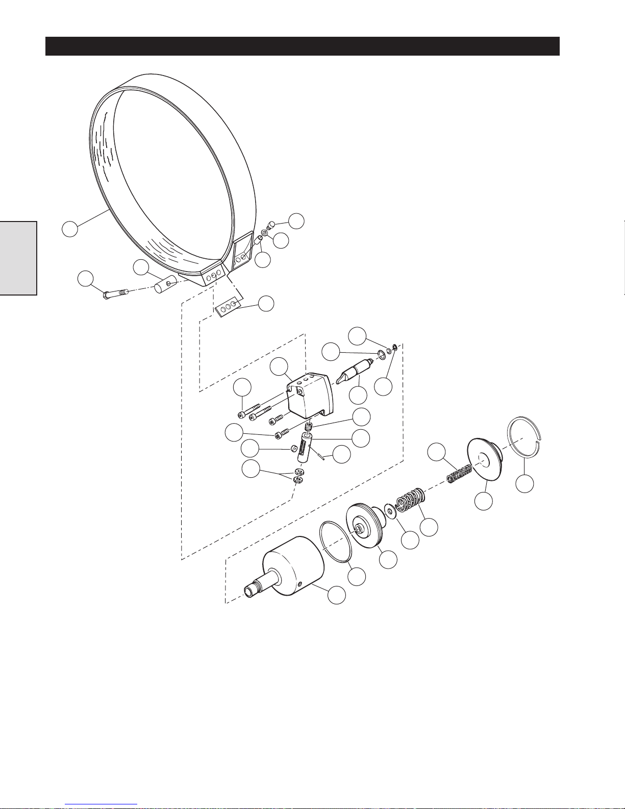
AUTOMATIC BAND BRAKE PARTS DRAWING
104
Section 3
120
119
112
107
116
117
103
105
102
106
101
109
115
110
111
108
113
114
127
126
125
(Dwg. MHP1080)
124
128
123
122
121
32
Page 33
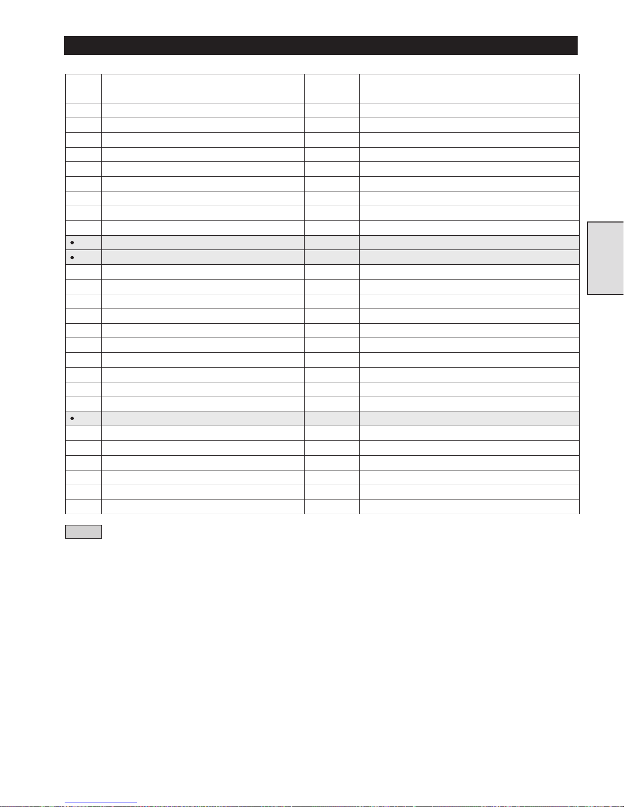
AUTOMATIC BAND BRAKE PARTS LIST
ITEM
NO.
DESCRIPTION
OF PART
TOTAL
QTY.
PART NO.
--- Brake Assembly 1 23890
101 Capscrew 3 71264808
102 Hardened Washers 3 21899
103 Spacer Tube 3 21891
104 Band Assembly 1 24367
105 Spacer 1 23029
106 Brake Bracket 1 22984
107 Capscrew 2 71264832
108 Cylinder Rod 1 23885
109 ‘O’Ring 1 71049423
110 ‘O’Ring 1 52662
111 Retainer Ring 1 54136
112 Capscrew 2 71264824
113 Spring 1 71126643
114 Plunger 1 23886
115 Dowel Pin 1 71144968
116 Roller 1 23883
117 Jam Nut 2 71267413
119 Pivot Bar 1 23755
120 Adjustment Bolt 1 71267405
121 Cylinder 1 23889
122 ‘O’Ring 1 52536
123 Piston 1 23884
124 Spring 1 71144943
125 Cover 1 23887
126 Retainer Ring 1 71126668
127 Spring 1 71144935
128 Washer 1 71145080
Recommended Spare
•
Section 3
33
Page 34
DIRECTIONAL CONTROL VALVE - GENERAL INFORMATION
Description
The air winch is controlled by a poppet type directional control
valve that is either lever operated at the winch or pendant
operated from a remote location. The winch operator can control
the winch drum direction and speed by moving a lever on the
winch control valve or by pressing a button on the remote
pendant. Materials used in the construction of the valve include
cast iron for the body, with corrosion resistant stainless steel and
bronze for the internal parts.
The poppets are designed for zero air leakage when the valve is
in the neutral position, and precise control of the air flow when
the valve is operated. Inlet air pressure provides a balancing
force on each inlet poppet to enhance control and reduce the
lever force on manually operated valves.
Incorporated in the directional control valve are an exhaust air
restrictor and a brake release valve for winches that are
equipped with a disc brake. The exhaust air restrictor allows the
winch operator to control the winch payout speed with the air
motor instead of using the brake. The brake release valve causes
the disc brake to release when the directional control valve lever
is moved or the pendant button is pressed to run the winch in
the payout direction.
When a winch is equipped with an automatic band brake, two
Section 4
brake release valves are installed in the control valve. One valve
releases the band brake when the lever moves to the haul-in
position and one releases the band brake when the handle moves
to the payout position.
then moved towards or away from the operator. This action
causes the control shaft to open the appropriate poppets and admit
air to the winch motor.
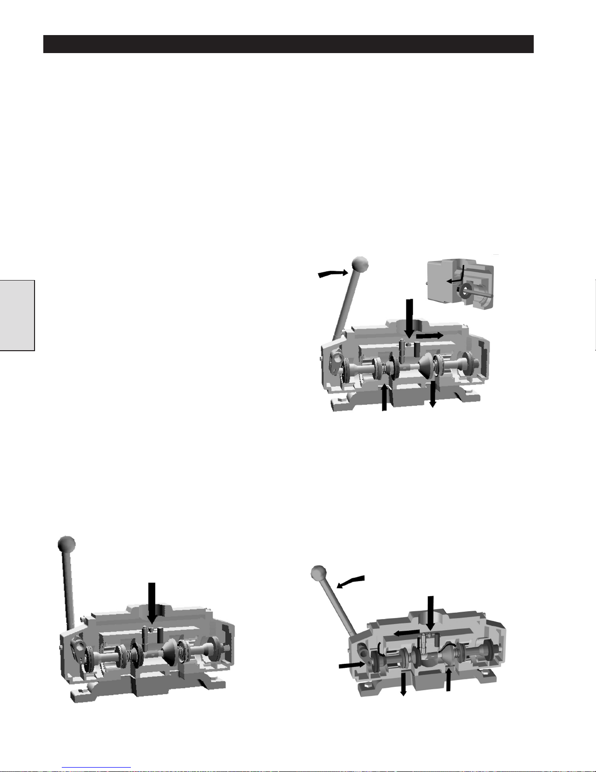
Payout
When the winch operator manually moves the directional
control valve lever to the right (when viewed from the motor
end), the control shaft slides to the left and causes the right hand
inlet poppet and the left hand exhaust poppet to open at the
same time. Refer to drawing MHP1186. The inlet poppet admits
high pressure air into the motor, and the exhaust restrictor
poppet controls the air leaving the motor through the secondary
exhaust port. This restriction regulates the payout speed of the
winch, reducing brake use and increasing operator control of
descending loads. If the winch is equipped with an automatic
disc and/or band brake, a sleeve on the valve shaft activates a
brake release valve(s) that release the brake(s).
Payout
Position
A shuttle valve, mounted on a block on the directional control
valve body, causes the brake release valve to release both the
band and disc brake in the payout direction, and causes only the
band brake to release in the haul-in direction.
Operation
The manual control lever pivots on a cross shaft running through
an end cap bolted to the valve body. The lever is spring loaded so
that the control valve returns and automatically locks into the
neutral position. A clevis attached to the cross shaft engages a
control shaft that runs lengthwise in the valve body.
Neutral
When the manual control lever is in the neutral position, no air is
admitted into the winch motor and the winch brake(s)
remains engaged. To run the winch, the directional
control valve lever must first be manually lifted and
Neutral
Position
(Dwg. MHP1186)
Haul-in
When the winch operator moves the manual control lever to the
left (when viewed from the motor end), the valve shaft slides to
the right and causes the left hand inlet poppet valve and the
right hand exhaust restrictor poppet to open at the same time.
Refer to drawing MHP1185. The inlet poppet admits high
pressure air into the motor, and the exhaust poppet allows air to
leave the motor through the secondary exhaust port. If the winch
is equipped with an automatic band brake only, a sleeve on the
valve shaft activates a brake release valve.
Haul-in
Position
(Dwg. MHP1184)
(Dwg. MHP1185)
3434
Page 35
Components
The directional control valve consists of an external handle, a
valve body which contains the valve spool, and two valve end
cap assemblies.
Function
The directional control valve regulates the direction and speed of
winch drum rotation. The control valve also acts to supply air to
the brake(s) depending on winch options and function selected.
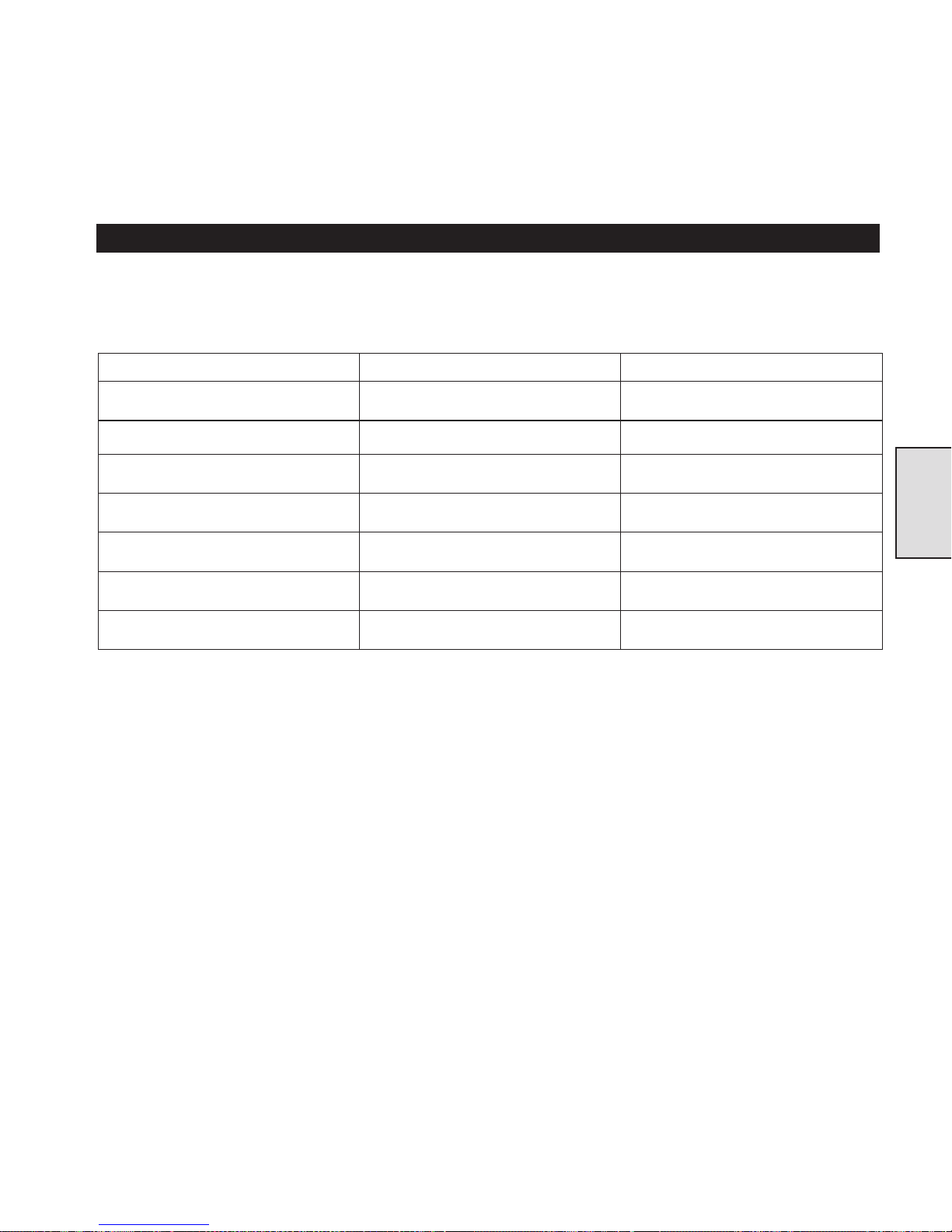
DIRECTIONAL CONTROL VALVE TROUBLE SHOOTING
This section provides basic troubleshooting information. Specific causes to problems are best identified by thorough inspections
performed by personnel instructed in safety, operation and maintenance of this equipment. The chart below provides a brief guide to
common direction control valve symptoms, probable causes and remedies.
Symptom Cause Remedy
No drum movement when control valve
actuated in Payout direction.
No drum movement when control valve
actuated in Haul-in direction.
Air escaping valve while in neutral
position.
Moving control handle in either direction
very hard.
Control handle in neutral position but
drum still rotating.
Control handle moves very easy in both
directions but no drum movement.
Unable to obtain rated line speed. Valve incorrectly adjusted. Adjust washers to provide correct
No air supply. Check air lines for rips or tears. Remove
shipping plugs.
Winch is overloaded. Reduce load.
Worn ‘O’ ring(s). Disassemble valve and replace ‘O’ ring(s).
Binding poppet. Disassemble valve and inspect.
Poppet valve stuck open. Disassemble valve and inspect.
Clevis pin sheared. Disassemble end cap and repair.
clearance.
Section 4
35
Page 36
DIRECTIONAL CONTROL VALVE MAINTENANCE
Read these instructions completely before working on the
Directional Control Valve.
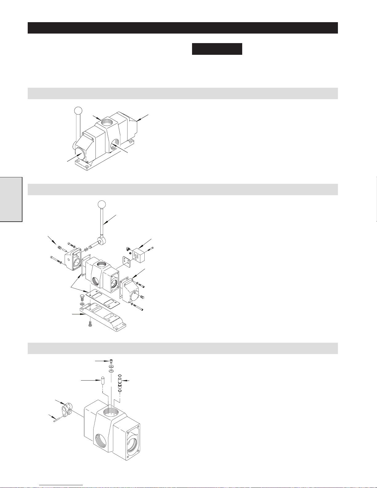
Removing Control Valve from Winch
Viewed from
Left Side
Viewed from
Rear
Viewed from
Right Side
(Dwg. MHP1121)
Separation of Components
Section 4
Plug
Gasket
Adapter
(Dwg. MHP1145)
Handle
Viewed from
Front
Shuttle
Valve
Valve Cap
NOTICE
comprised of components that
have very close tolerances. The
valve components should only be disassembled to
make a repair. Disassembly of good components can
cause additional damage.
1. Remove brake air line.
2. Remove muffler or exhaust hose.
3. Disconnect inlet air line.
4. Using a pipe wrench, remove inlet hose adapter.
5. Loosen capscrews (442) and flatwashers (434). Take valve
assembly to clean work bench. Capscrews (442) cannot be
removed until end caps or adapter are removed.
1. Remove capscrews (441) and separate valve adapter (440)
from valve body (410), discard gasket (424). Remove
capscrews (442) and flatwashers (434).
2. Remove capcrews (439 and 437) and washers (433) from valve
cap (438). Using a soft face hammer remove valve cap (438)
and discard gasket (411).
3. Remove the plug (447) from valve cap (450). Pin (445) has
internal threads. Install an 8-32 x 2 inch screw into pin. Pull
out pin (445).
4. Lift up valve handle assembly slightly, to remove pressure on
pin (463). Press handle assembly out of valve cap (450).
5. Remove capcrews (439 and 437) and washers (433) from valve
cap (450). Using a soft face hammer remove valve cap (450).
6. Remove capscrews (418) from shuttle valve body (479) and
remove shuttle valve.
7. Remove fittings (this depends on the winch options).
8. Remove gasket (419) and discard.
The directional control valve is
Disassembly of Valve Body
Capscrew
Pin
Clevis
Pin
(Dwg. MHP1146)
Brake Release
Valve
1. Press out pin (409) from clevis (446) and slide clevis off shaft
(401).
Entering from air inlet.
2. Remove capscrew (465), washer (417) and spring clip (416).
3. Lift out brake release valve assembly (413) or pin (412)
depending on winch options.
36
Page 37
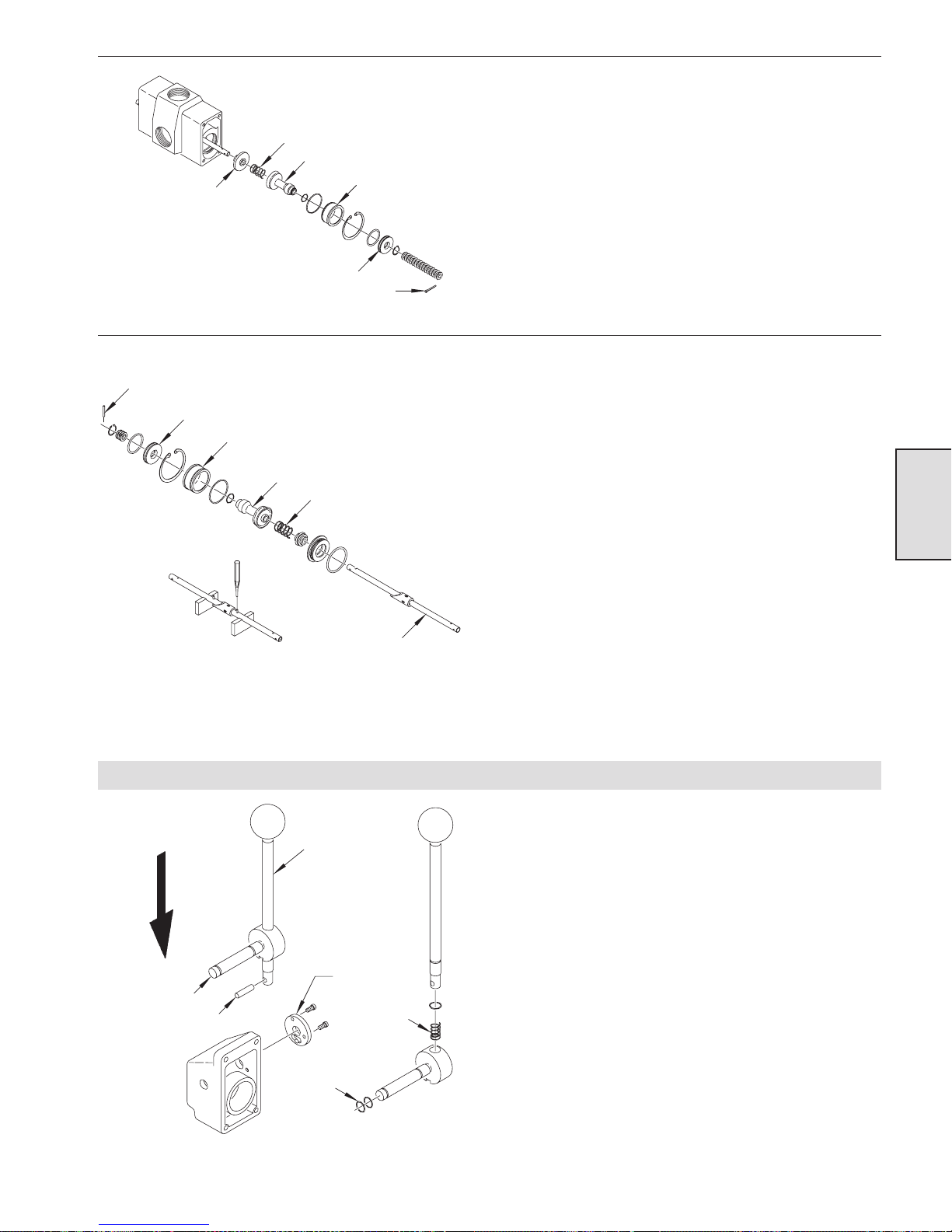
Exhaust Poppet
(Dwg. MHP1147)
Roll Pin
Valve Piston
(Dwg. MHP1148)
Spring
Valve Piston
Poppet Seat
Inlet Poppet Assembly
Inlet Poppet Assembly
Poppet Seat
Cotter Pin
Spring
Valve Shaft
Starting at front of the valve body.
4. Remove cotter pin (414) from shaft (401) and take off washers
(434).
5. Remove retainer ring (429).
6. Pull poppet subassembly out of valve body.
7. Remove retainer (432) and seperate piston valve (431) from
inlet poppet, remove ‘O’ ring (430) from outside of valve
piston and ‘O’ ring (426) from inside of valve piston.
8. Seperate poppet seat (428) from inlet poppet and remove ‘O’
ring (427).
19. Remove spring (422).
10. Remove exhaust poppet (420).
Turn the valve around and finish disassembly.
11. Remove roll pin (406) and shims (444).
12. Remove retainer ring (429). Remove shaft (401) with the rest
of the valve assembly. This step might require shaft (401)
being tapped from front end of valve body. The ‘O’ ring in the
restrictor seat (403) might create a tight fit.
13. Pull poppet subassembly out ot valve body.
14. Remove retainer (432) and seperate piston valve (431) from
inlet poppet, remove ‘O’ ring (430) from outside of valve
piston and ‘O’ ring (426) from inside of valve piston.
15. Seperate poppet seat (428) from inlet poppet and remove ‘O’
ring (427).
16. Separate inlet poppet assembly (423) from shaft (401).
17. Slide spring (422) off of shaft (401).
18. Slide restrictor poppet (402) off shaft (401).
19. Slide restrictor seat (403) off of shaft (401), remove ‘O’ ring
(404) and discard.
20. Using a suitable punch, tap out roll pins (405).
21. Back off setscrew (407) and slide sleeve (408) off shaft (401).
Section 4
Handle Disassembly
Valve Handle
Cross Shaft
Pin
‘O’Rings
(Dwg. MHP1149)
1. Push pin (463) out of valve handle (449).
2. Catch spring (462).
3. Remove ‘O’ ring (460).
4. Unscrew handle ball (469).
5. Remove ‘O’ rings (448) from cross shaft (461).
6. Remove capscrews (465) and then detent plate (464).
Detent Plate
Spring
37
Page 38
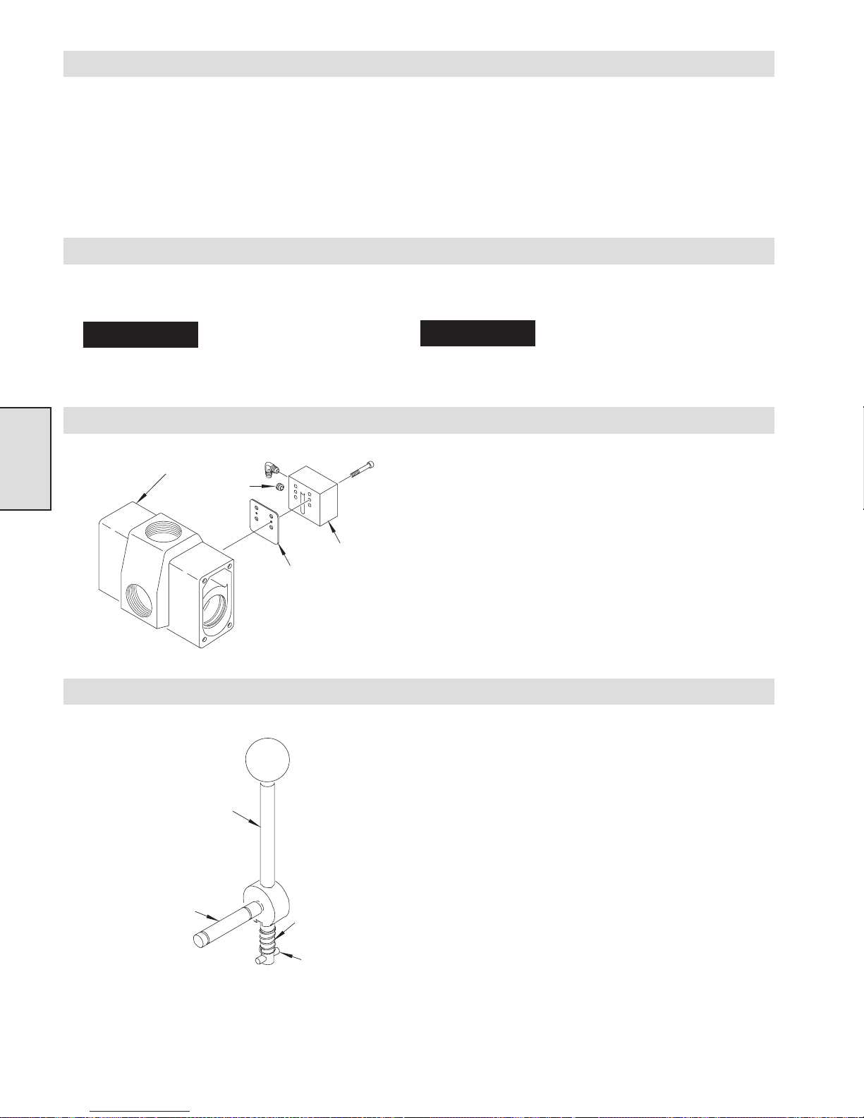
Inspection
1. Inspect the bores in the valve body and end caps, for
pitting, scratches or other signs of abnormal wear. Clean
and lightly hone.
2. Replace ‘O’ rings in all components disassembled. Replace
any steel components (not the valve body) that are showing
sign of corrosion.
3. Inspect springs, looking for signs of cracks, bulging, or
corrosion.
4. Set springs on a flat surface, springs should stand straight up.
If springs have any abnormal appearance, replace.
5. Ensure that valve components are kept clean during repair. Dirt
or other contaminates can cause damage to new parts.
Directional Control Valve Assembly and Installation
During control valve assembly lubricate all ‘O’ rings with DOW CORNING #111 lubricant.
NOTICE
other lubricants may cause valve malfunctions.
DOW CORNING #111 lubricant
is the ONLY factory authorized
lubricant for this valve. Use of
NOTICE
remove any burrs or debris). Also remove any coating
from machined surfaces to ensure a proper fit.
Shuttle Valve Assembly
Section 4
Valve
Body
Plug
Gasket
Shuttle
Valve
1. Place a bead of pipe sealant around threads of fittings installed
in lower port on shuttle valve body (479) and tighten.
2. Place capscrews (418) into shuttle valve body(479) and slide
gasket (419) onto the capscrews. Match capscrews to mounting
holes in valve body (410) insert and tighten to 24 to 30 inch lb.
(8.9 - 3.0 Nm).
When installing new end caps,
valve body or valve adapter, clean
all threaded holes with a tap (to
(Dwg. MHP1150)
Handle Assembly
Valve Handle
Cross Shaft
(Dwg. MHP1151)
1. Apply Loctite® 242 on threads of valve handle (449). Screw
handle ball (469) onto valve handle (449) and tighten.
2. Slide ‘O’ ring (460) onto valve handle (449) and lubricate.
Insert this assembly into cross shaft (461).
3. Slide spring (462) onto lower portion of valve handle (449).
4. Press pin (463) into valve handle. Pin should protrude about
1/16 inch (1.6 mm) from one side. Long side of pin should fit
into slot in the cross shaft and not bind when moved up and
down.
Spring
Pin
38
Page 39
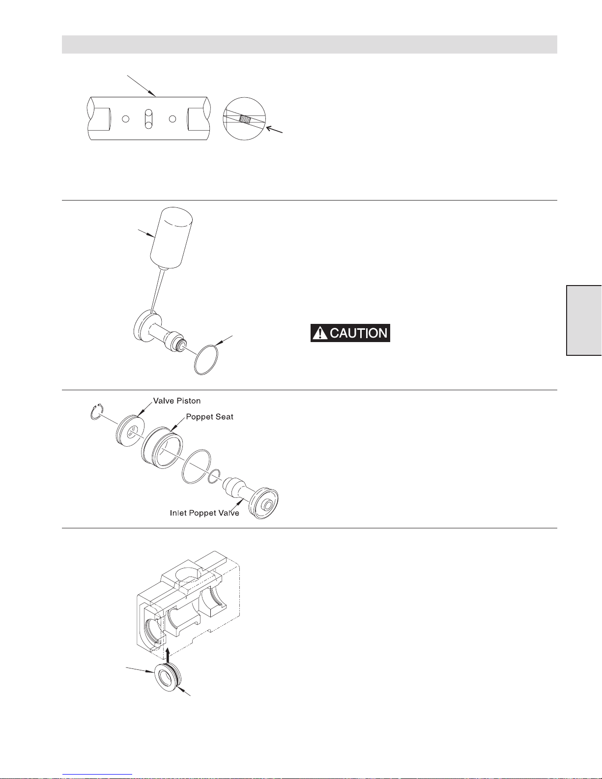
Valve Body Assembly
Valve Shaft
(Dwg. MHP1022)
Loctite
1. Insert setscrew (407) into the center hole in shaft (401) from
bottom position. Center threaded hole is offset 18° (degrees)
from the two other holes and flats on shaft.
2. With the flats on shaft (401) facing you, slide sleeve (408)
onto shaft (401). The flat part of the sleeve should be on the
right with the 45º (degrees) on the left.
3. Press roll pins (405) into shaft (401) until pins are exposed
equally on both sides of the shaft.
4. Ensure that inlet poppet is at room temperature 70° F (21° C).
®
5. Clean both inlet poppet (423) and ‘O’ ring with a non-residue
cleaner. Electrical contact cleaner works well, blow dry with
clean, dry compressed air.
®
6. Apply a continuous bead of Loctite
4212 to the groove in the
inlet poppet.
‘O’Ring
7. Slide ‘O’ ring over inlet poppet and into the groove. Press ‘O’
®
ring into groove all around and wipe excess Loctite
®
from poppet surface. Allow Loctite
4212 to cure.
4212
Wear rubber gloves while installing
‘O’ rings. The cleaner can cause
skin irritation. Loctite
®
4212 is very
Section 4
sticky and hard to clean off skin.
(Dwg. MHP1152)
(Dwg. MHP1153)
Restrictor
Seat
8. Assemble both poppet valves.
a. Lubricate the ‘O’ ring on the inlet poppet valve (423).
b. Lubricate ‘O’ ring (427) and place it on poppet seat (428).
Place this assembly on poppet valve (423).
c. Lubricate ‘O’ ring (426) and place on poppet valve (423).
d. Install valve piston (431) on poppet valve and secure with
retainer (432).
9. Place ‘O’ ring (404) onto restrictor seat (403) and lubricate.
10. Insert restrictor seat (403) up through bottom of valve body
and into inner bore position. Press restrictor seat into valve
body until seated.
(Dwg. MHP1023)
‘O’Ring
39
Page 40
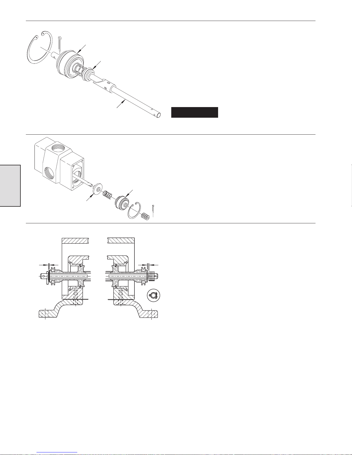
Poppet Assembly
Restrictor Poppet
Assemble valve components onto shaft (401) in the following order.
11. With the 45° degree side of sleeve (408) facing left, slide
restrictor poppet (402) onto the left side with the bevel portion
of poppet facing the sleeve.
12. Slide spring (422) on next followed by poppet assembly with
large end towards sleeve. Insert pin (414) into shaft (401) to
retain components (do not bend).
13. From the back of the valve body, carefully slide this assembly
into valve body. Use fingers to press poppet seat into valve
body.
14. Insert retainer ring (429) into valve body.
(Dwg. MHP1154)
Section 4
(Dwg. MHP1155)
0.03 to 0.05
(0.8 to 1.3 mm)
Exhaust
Poppet
Valve Shaft
Poppet
Assembly
0.06 to 0.12
(1.5 to 3 mm)
NOTICE
The flats on shaft (401) must be
facing the left (or pilot valve) side
of the valve body.
Move to the front of the valve body
15. Slide exhaust poppet (420) over shaft (401), from the front of
the valve body. Push into valve body, followed by spring
(422).
16. Slide poppet assembly on to shaft (401). Use fingers to press
poppet seat into valve body.
17. Install retainer ring (429) into valve body.
18. At the rear of the valve, use washers (434) as required to
establish a clearance between pin (406) and inlet poppet (423),
of 0.03 to 0.05 inches (0.8 to 1.3 mm). Then press pin into
shaft (401) until pin is level with top of washer(s).
19. At the front of the valve, use washers (434) as required to
establish a clearance between the washers and inlet poppet
(423) of 0.06 to 0.12 inches (1.5 to 3 mm). Then insert cotter
pin (414) into shaft and bend ends over.
20. Place ‘O’ rings (430) into grooves on both piston valves (431)
and lubricate.
(Dwg. MHP1181)
40
Page 41
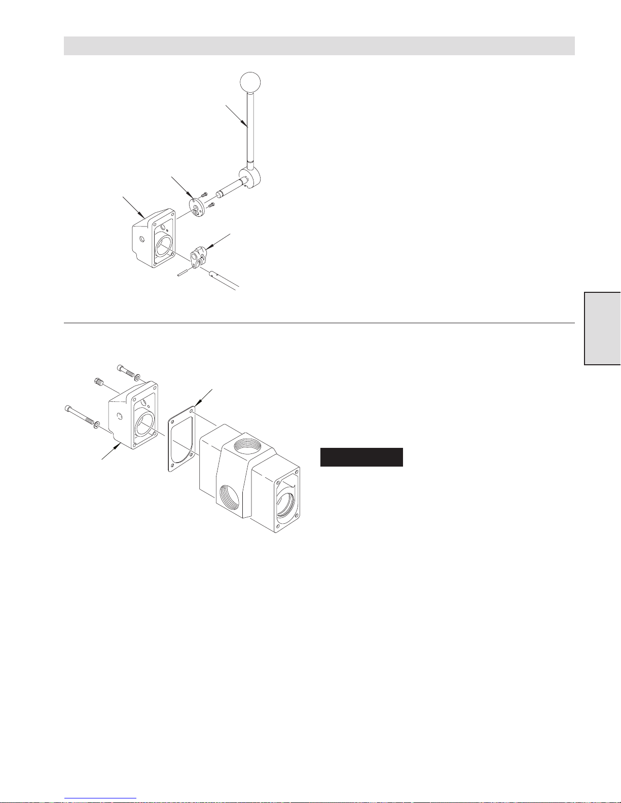
Control Handle End Cap Assembly
Valve Handle
Detent Plate
End Cap
Clevis
(Dwg. MHP1156)
Gasket
1. Place the split portion of valve clevis (446) over shaft (401),
with large portion on top of shaft and rounded portion of valve
®
clevis facing valve body. Apply Loctite
609 on roll pin (409).
Tap roll pin (409) through valve clevis and shaft until centered
in clevis.
®
2. Apply Loctite
680 on threads of capscrews (465) and insert
into detent plate (464). Insert cross shaft (461) without ‘O’
rings into end cap (450). Place detent plate on cross shaft and
align with mounting holes in end cap (450). Insert capscrews
(465) and tighten to 42 to 45 in. lbs. (15.5 to 16.7 Nm). Ensure
that cross shaft rotates freely and then remove.
3. Place valve body (410) on its side with the clevis end over the
edge of the workbench.
4. Place gasket (411) on valve cap (450) and slide assembly over
clevis. Lubricate threads and loosely install capscrews (437)
and (439) and washers (433).
5. From the bottom hole in valve cap use a punch, or similar tool,
to align the cross shaft holes in valve cap with the hole in the
clevis. Use tool to maintain position and tighten capscrews to
54 to 60 inch lbs (20 to 22 Nm).
Section 4
The slotted pin grooves in the
End Cap
NOTICE
clevis (where clevis and shaft
(401) are joined) make alignment
of the cross shaft and clevis difficult. To prevent binding
of cross shaft during installation, ensure the cross shaft
holes (located in valve cap) and the clevis hhole are
aligned before installing cross shaft.
6. Lubricate ‘O’ rings (448) and locate in grooves on cross shaft
(461). Insert cross shaft through detent plate side of valve cap
assembly. To complete, raise handle assembly up and insert
pin (463) into detent plate while pushing on cross shaft.
7. Align the hole in the cross shaft with the hole in the end of the
®
clevis. Apply a bead of Loctite
242 to pin (445). Using a
8-32 x 2 inch screw attached to the threaded end of pin, install
pin by tapping into position. Ensure pin is inserted fully into
clevis.
8. Operate the lever in both directions. There should be no
indication of sticking or binding. When released, the lever
must return to the neutral position and lock in place (handle
must be lifted before shifting in either direction).
(Dwg. MHP1157) 9. Place pipe thread sealant on the threads of plug (447), insert it
into end cap (450) and tighten.
41
Page 42
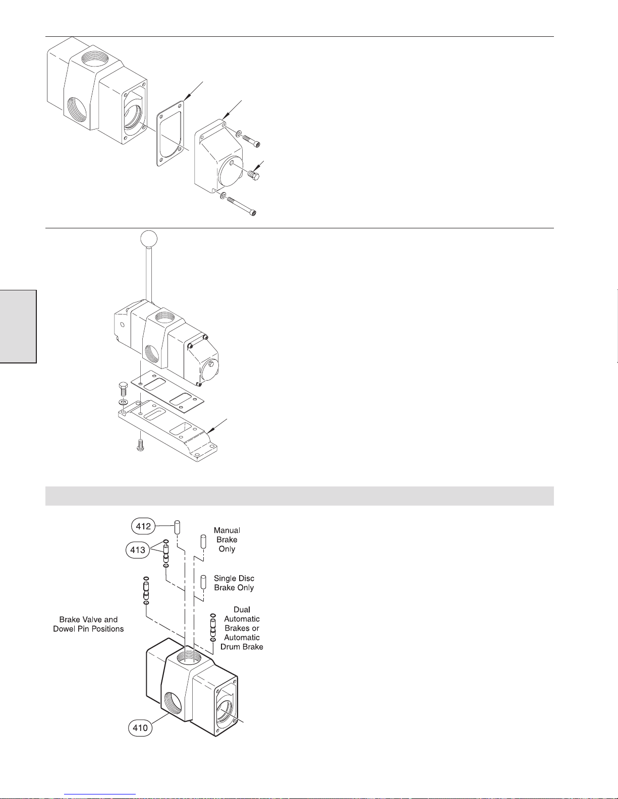
(Dwg. MHP1158)
Gasket
Valve
Cap
Plug
10. Insert capscrews (437) and washers (433) through top
mounting holes in valve cap (438). Place gasket (411) on
capscrews, insert these into valve body and loosely tighten.
11. Insert capscrews (439) and washers (433) through bottom
mounting holes. Tighten capscrews (437 and 439) to 54 to 60
inch lbs. (20 to 22 Nm).
12. Place pipe thread sealent on the threads of plug (436), insert
into valve cap (438) and tighten.
13. Insert capscrews (442) and flatwashers (434) into adapter
(440). These capscrews cannot be removed without:
a. Removing end caps or,
b. Removing adapter from valve body.
®
14. Apply Loctite
242 on threads of capscrews (441). Install
capscrews through adapter (440) and gasket (424). Insert these
into mounting holes in valve body and tighten to 13 to 17 ft lbs
(58 to 76 Nm).
Section 4
Adapter
(Dwg. MHP1159)
Brake Release Valve Installation and Adjustment
1. Press brake valve (413) into valve body. Brake valve has one
end that is longer. This end should be down (in the valve
body).
(Dwg. MHP1227)
42
Page 43
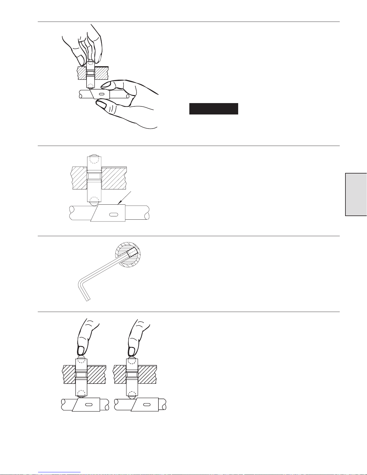
2. Rotate sleeve (408) 180º (degrees) or until long portion of
sleeve is on top.
3. Using fingers on the brass body, press brake valve (413) into
the valve body until steel ball is in firm contact with sleeve
(408).
4. Rotate sleeve (408) 180º (degrees) or until the long portion of
sleeve is on the bottom.
5. Apply Loctite® 609 to pin (412) and push into valve body
(through air inlet) until 0.16 to 0.25 inch (4 to 6.5 mm) is
exposed above surface.
(Dwg. MHP1024)
(Dwg. MHP1027)
Sle eve
NOTICE
poppet seat, resulting in erratic winch operation.
6. Insert capscrew (465) through flatwasher (417) and spring
retainer (416) into valve body and tighten.
7. Adjusting brake valve (413). Ensure that long portion of sleeve
(408) is on the bottom of shaft (401) and align a slot in sleeve
with center threaded hole in shaft.
8. Slide sleeve fully up to steel ball in brake valve.
9. Insert allen wrench through slot in sleeve and tighten setscrew
(407) against far side of sleeve. Locking sleeve into position.
Avoid using excessive Loctite
609. Loctite can drip onto shaft
(401) causing shaft to stick in
®
Section 4
(Dwg. MHP1025)
(Dwg. MHP1026)
10. Check operation of brake valve. Press control lever assembly
to the front (haul-in) position at the same time using your
finger to feel the top steel ball. The ball should rise
immediately. When the control handle is returned to neutral,
the ball should drop.
43
Page 44
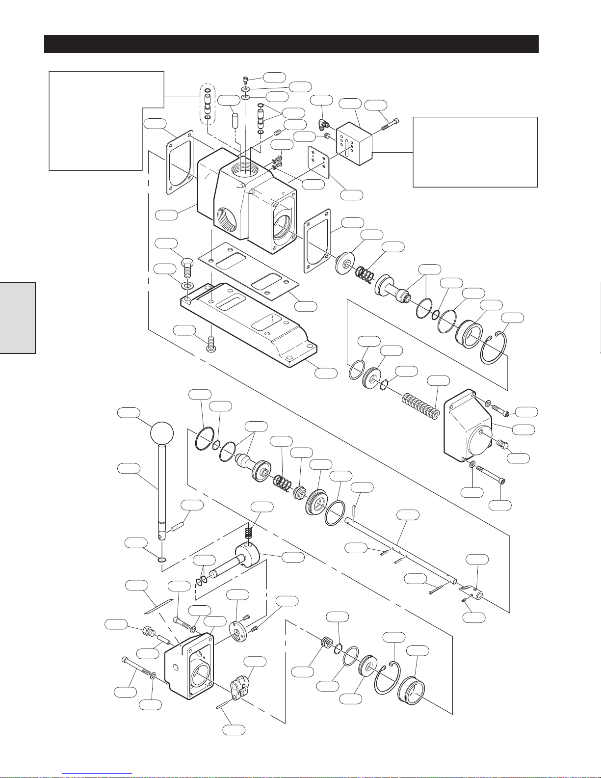
DIRECTIONAL CONTROL VALVE PARTS DRAWING
Single Air Brake:
Qty.=1eachofItem412
and Item 413.
Dual Air Brake:
Qty.= 2 of Item 413,
0ofItem412.
No Air Brake:
Qty.= 2 of Item 412,
0ofItem413.
Section 4
411
410
442
434
441
412
465
416
470
417
413
421
435
424
471
425
479
419
411
418
Note: For specific fitting
combinations refer to
Dwg. MHP0764.
Combination (item 425 and
435) shown is for single air
brake equipped winch.
420
422
423
426
427
428
429
430
431
447
469
449
439
460
443
445
433
437
463
427
448
433
426
450
464
423
446
462
422
465
461
402
444
440
403
430
404
432
405
431
406
432
434
437
438
436
433
439
401
408
414
407
429
428
(Dwg. MHP0654)
409
44
Page 45
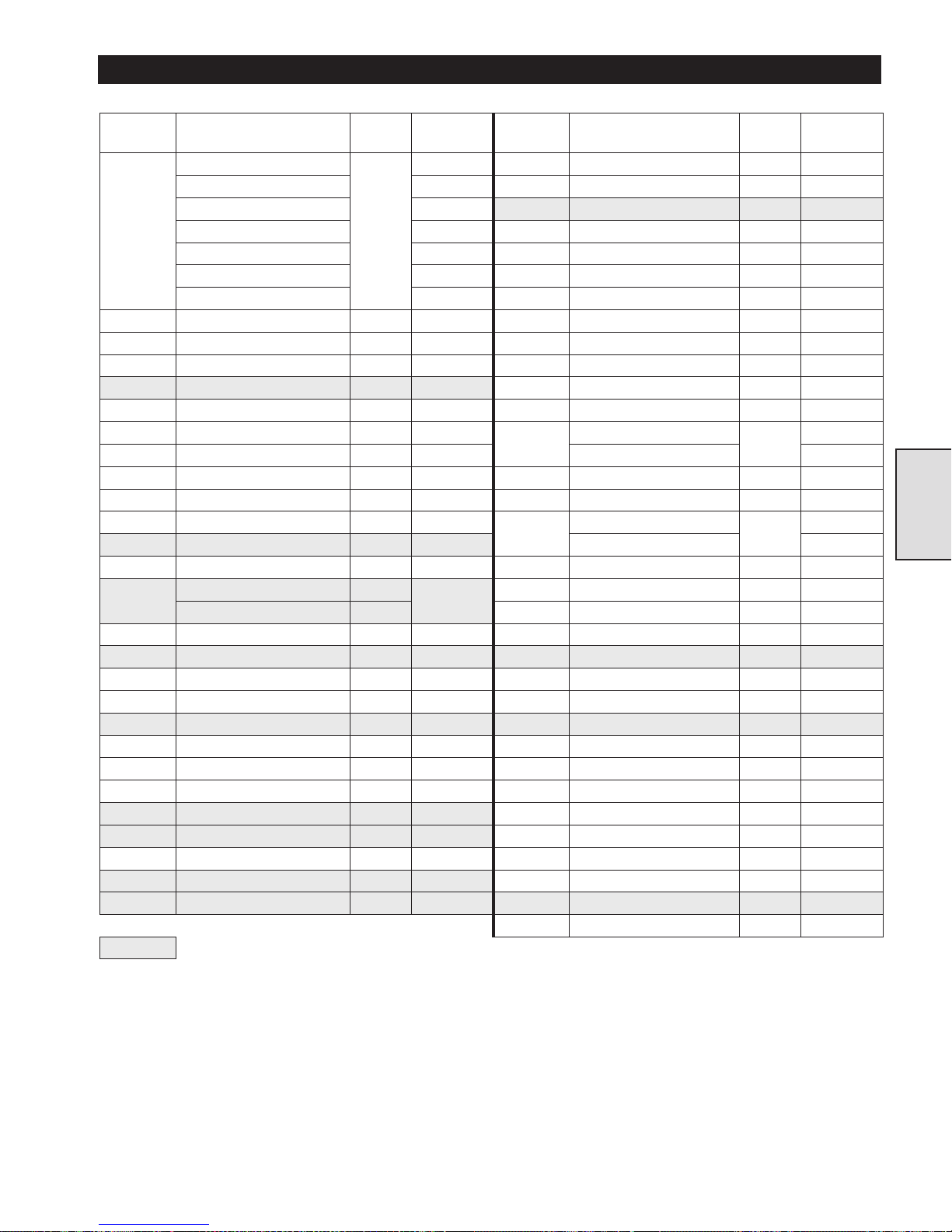
DIRECTIONAL CONTROL VALVE PARTS LIST
ITEM
NO.
DESCRIPTION
OF PART
QTY
TOTAL
PA R T
NUMBER
ITEM
NO.
DESCRIPTION
OF PART
QTY
TOTAL
PA R T
NUMBER
400
Valve Assembly *
1
--- 428 Poppet Seat 2 23518
Single Air Brake 24801 429 Retainer Ring 2 53833
Single Air Brake - CE * 25451 430 ‘O’ Ring 2 52573
Dual Air Brakes 24803 431 Valve Piston 2 23519
Dual Air Brakes - CE * 25442 432 Retainer Ring 2 71138010
Without Air Brakes 24804 433 Washer 8 71271985
Without Air Brakes - CE * 25443 434 Washer † 53881
401 Valve Shaft 1 23522 435 Plug ‡ 71069009
402 Restrictor, Poppet 1 23523 436 Plug 1 71303689
403 Restrictor, Seat 1 23524 437 Capscrew 4 71138069
404 ‘O’Ring 1 71137988 438 Valve Cap 1 23520
405 Pin 2 71293179 439 Capscrew 4 71138077
406 Pin 1 71293161
440
Adapter, Standard
1
23514
407 Setscrew 1 71138093 Adapter, CE 24373
408 Sleeve 1 23606 441 Capscrew 4 71138085
409 Pin 1 71149157 442 Capscrew 4 53890
410 Valve Body 1 24795
443
Label, Standard
1
71148290
411 Gasket 2 23592 Label, CE 96180102
412 Pin ** 71146195 444 Shim † 71138119
413
Valve Assembly **
23594
445 Pin 1 71145379
‘O’ Ring (each assembly) 2 446 Clevis 1 23589
414 Pin, Cotter 1 71287478 447 Plug 1 25498
416 Spring Clip 1 24793 448 ‘O’ Ring 2 71137962
417 Washer 1 50899 449 Handle 1 23747
418 Capscrew 2 71261747 450 Valve Cap 1 23607
419 Gasket 1 23744 460 ‘O’ Ring 1 71146963
420 Exhaust Poppet 1 23516 461 Cross Shaft 1 23746
421 Plug 1 51897 462 Spring 1 71146948
422 Spring 2 71138028 463 Pin 1 71146955
423 Inlet Poppet Assembly 2 24139 464 Detent Plate 1 23748
424 Gasket 1 71264725 465 Capscrew 3 53807
425 Fitting, Elbow ‡ 71262299 469 Knob 1 71138051
426 ‘O’Ring 2 52662 470 Capscrew 2 71303671
427 ‘O’Ring 2 51768 471 Seal Washer 2 71303838
479 Shuttle Valve Body 1 23739
Recommended spare.
*
Valve Assembly (Item 400) consists of Items 401 through 417, 420 through 424, 426 through 434 and 436 through 471.
**
Refer to the following to determine Pin (Item 412) and Valve Assembly (Item 413) configuration requirements:
1. Winches without disc or automatic drum band brake (Valve Assemblies 24804 or 25443) use quantity of 2 Pins (Item 412).
2. Winches with a single automatic brake (disc or drum band) (Valve Assemblies 24801 or 25451) use quantity of 1 Pin (Item
412) and quantity of 1 Valve Assembly (Item 413).
3. Winches with disc and automatic drum bank brakes (Valve Assemblies 24803 or 25442) use quantity of 2 Valve Assemblies
(Item 413).
†
Quantity of 4 Washers (Item 434) required to mount Adapter (Item 440). Additional Washer (Item 434) and Shim (Item 444)
quantities = ‘As Required’ to establish clearance tolerances described in “MAINTENANCE” section.
‡
Refer to Dwg. MHP0764 to determine Shuttle Valve (Item 479) configuration.
•
•
•
•
••
••
•
•
•
••
•
Section 4
45
Page 46
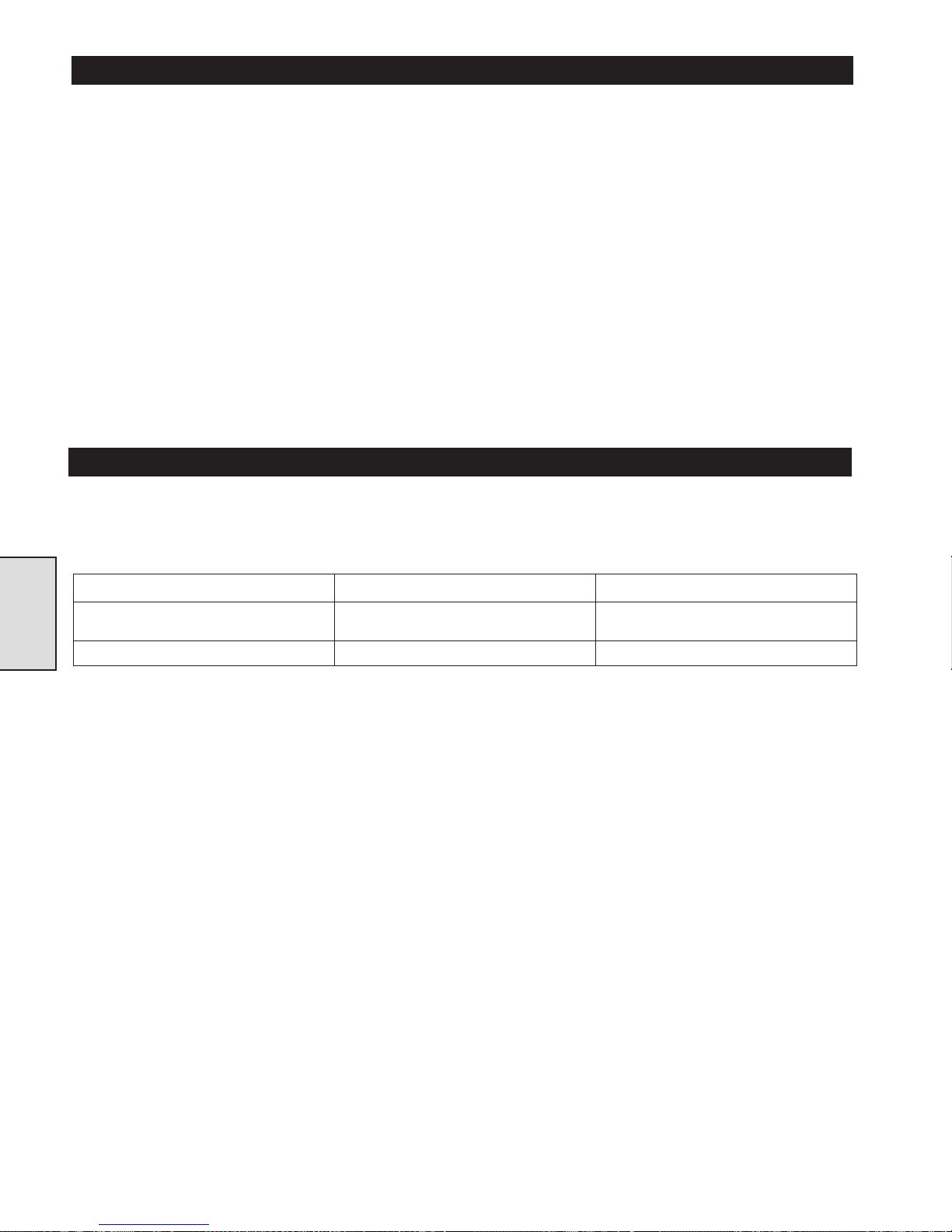
REDUCTION GEAR - GENERAL INFORMATION
Description
The reduction assembly is a planetary gear type design. There
are two planetary stages used in this reduction gear to achieve a
43:1 reduction. The air motor provides input to the first stage
sun gear which turns the planet gears. The first stage planet
gears are connected to the planet carrier which is connected to
the sun gear of the second stage. The sun gear in the second
stage drives the planet gears, in the second stage, which are
connected to the planet carrier. The planet carrier in the second
stage is connected to the outboard upright through the output
shaft. This prevents planet carrier rotation. Rotation of the
second stage planet gears causes the reduction gearbox housing
to rotate. The housing is connected to the drum by the cover and
capscrews.
Operation
Depending on which direction (clockwise or counterclockwise)
the input shaft is turning will determine the direction of drum
rotation. The speed of drum rotation is dependent on the speed
of the input shaft. This allows the operator to vary the drum
speed by controlling air motor speed. Planetary gears are not
inherently self locking (as are some other types of gearing) it is
therefore important that the braking systems work properly.
REDUCTION GEAR TROUBLESHOOTING
This section provides basic troubleshooting information. Specific causes to problems are best identified by thorough inspections
performed by personnel instructed in safety, operation and maintenance of this equipment. The chart below provides a brief guide to
common reduction gear symptoms, probable causes and remedies.
Symptom Cause Remedy
Grinding noise or excessive vibration when
rotating.
No drum rotation Broken gear teeth. Disassemble, inspect and repair.
Section 5
Worn bearings or thrust washers. Disassemble, inspect and repair.
46
Page 47
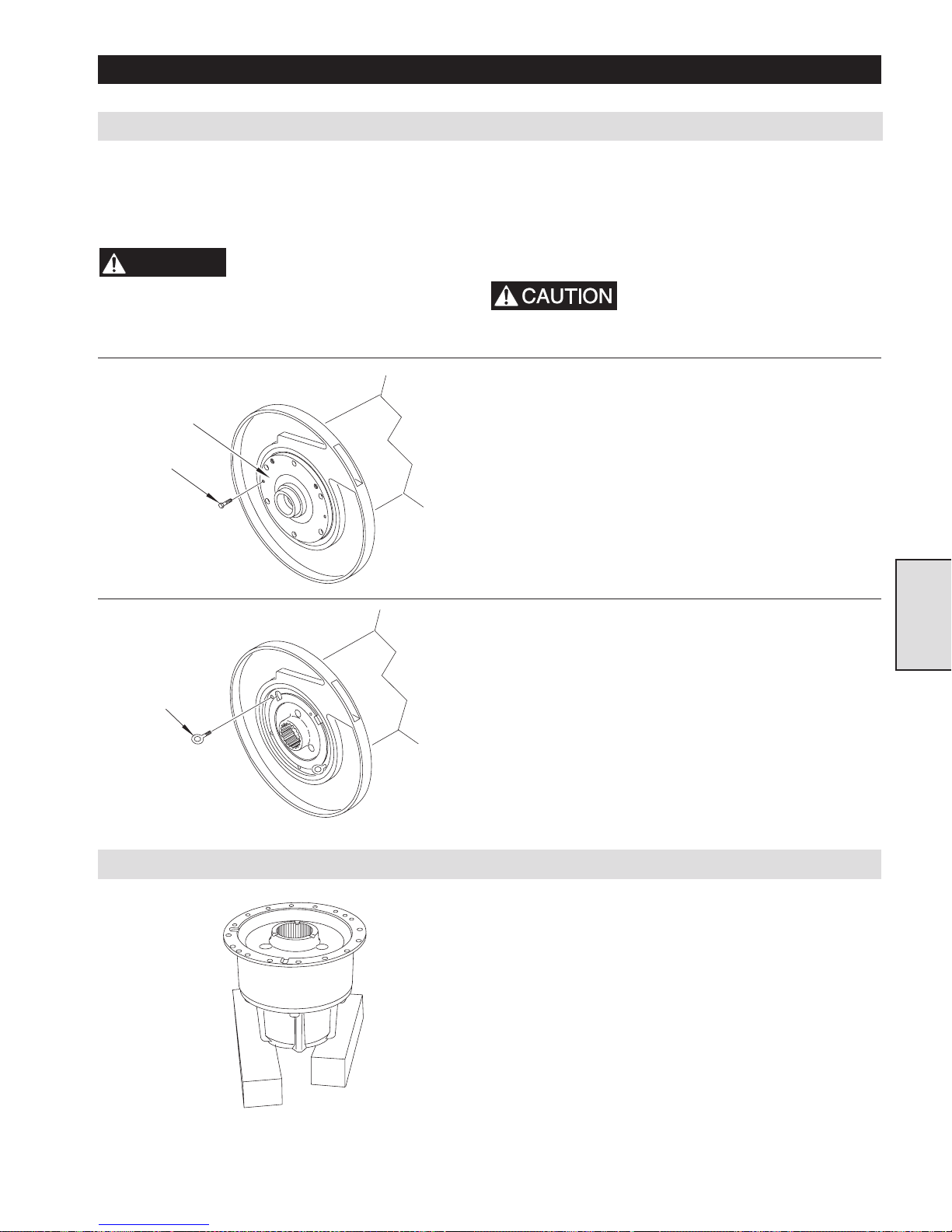
Reduction Gearbox Removal
REDUCTION GEAR MAINTENANCE
1. Rotate gearbox until drain plug is in lowest position (refer
to “LUBRICATION” Section).
2. Drain lubricant into a clean container and observe for
particles or metal shavings which might indicate a problem
and help to identify the cause.
WARNING
3. Remove disc brake.
Cover
7/16 x 20 x 1 inch
Capscrew
(Dwg. MHP1182)
Shutoff, bleed down and
disconnect the air supply line
before performing any
disassembly procedures.
4. Remove cover (4) and gasket (19) from outboard upright (26).
5. Remove output shaft (28).
6. Remove capscrews (86) from sideframes (78) at outboard
upright (26). Loosen capscrews (86) at the motor upright (27).
7. Support drum (77). Attach lifting/pulling device to outboard
upright (26) and remove winch mounting bolts. Pull outboard
upright free from drum.
There will be lubricant seepage
in area, use appropriate material
to absorb lubricant.
8. Use two 7/16 - 20 x 1 inch capscrews and thread them into the
two threaded holes in the end cover (33).
9. Tighten both capscrews evenly until seal between the cover
(33) and drum (27) is broken, remove cover (33) and thrust
washer (36).
Section 5
Eye Bolt
(Dwg. MHP1183)
Reduction Gearbox Disassembly
10. Use two 1/2 - 13 x 1 inch eye bolts and thread them into the
two threaded holes in housing (44).
11. Tighten both eyebolts evenly until seal between housing and
drum is broken.
12. Attach a suitable lifting device to the eye bolts and carefully
pull reduction gear assembly out of drum. Move to a clean
sturdy workbench.
1. Support the housing assembly on two blocks.
(Dwg. MHP1167)
47
Page 48
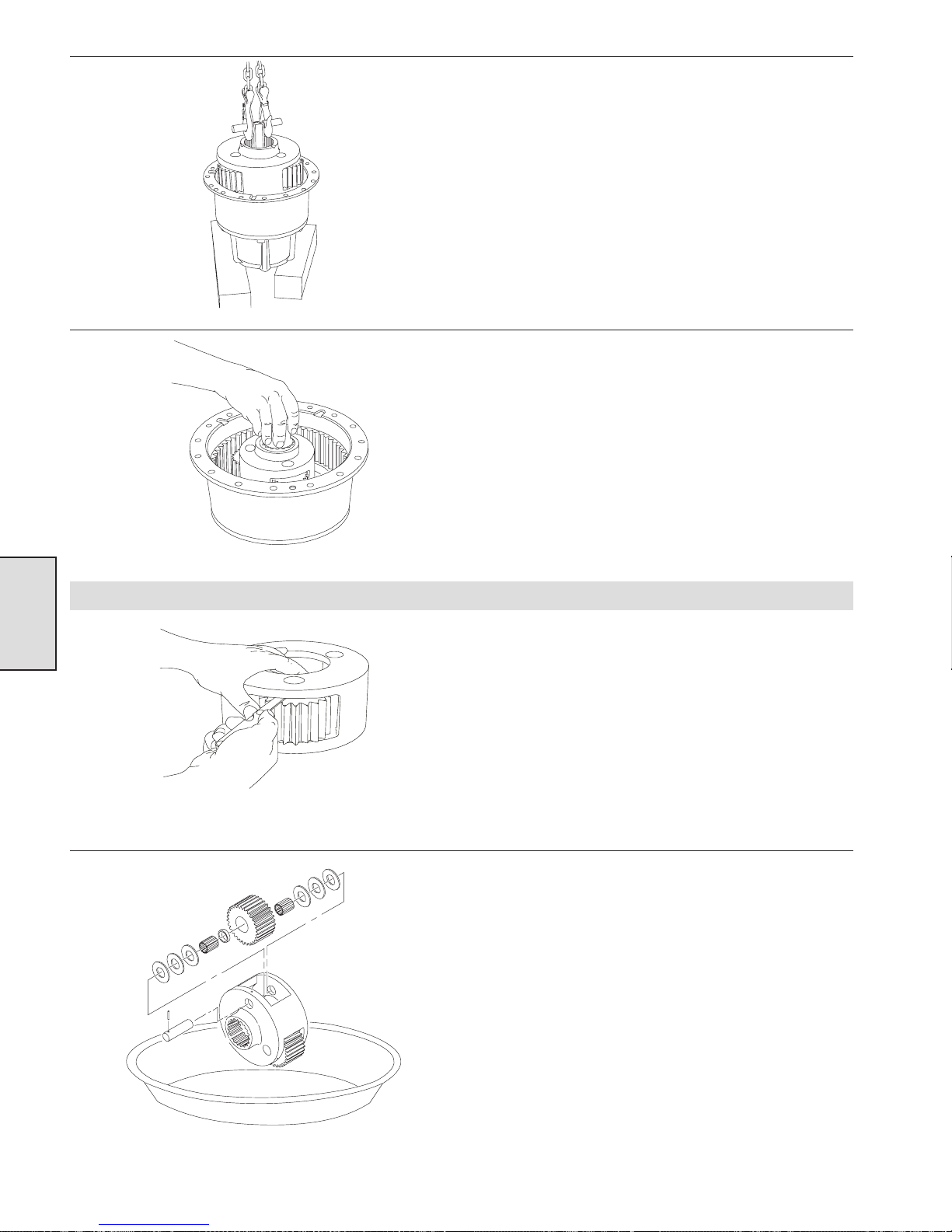
(Dwg. MHP1168)
2. Insert a suitable lifting jig into the output carrier assembly (3)
and lift assembly out of housing.
3. Grip output sun gear (45) and pull out intermediate carrier
assembly (4).
4. Remove retainer ring (53) from output sun gear (45) and push
out of carrier.
5. Remove intermediate sun gear (54). Remove thrust washers
(63 and 65) and bearing (67) from sun gear.
6. Remove oil seal (71) and bearing (67) from back side of
housing (69)
7. Remove capscrews (68) and separated housings (44 and 69).
(Dwg. MHP1160)
Output Carrier Disassembly
Section 5
(Dwg. MHP1169)
Prior to disassembly check planet gear side clearance, 0.005 to
0.032 inches (0.13 to 0.81 mm). Spin gears, gears should rotate
freely. If gears are tight or clearance is incorrect, disassemble planet
assembly.
1. Tap roll pin (38) completely into output planet pin (35).
2. Place carrier in a wide shallow container or on a clean shop
towel. Each gear contains 42 needle bearings (41) that may fall
out as the output carrier is disassembled.
3. Push out output planet pin (35). Remove thrust washers (34,
40, and 42), needle bearings (41), and spacer (59). Thrust
washers (34, 40, and 42) are used in combination to achieve
clearance, all three might not be present or quantities may
vary.
4. Tap roll pin (38) out of output planet pin (35).
(Dwg. MHP1222)
48
Page 49
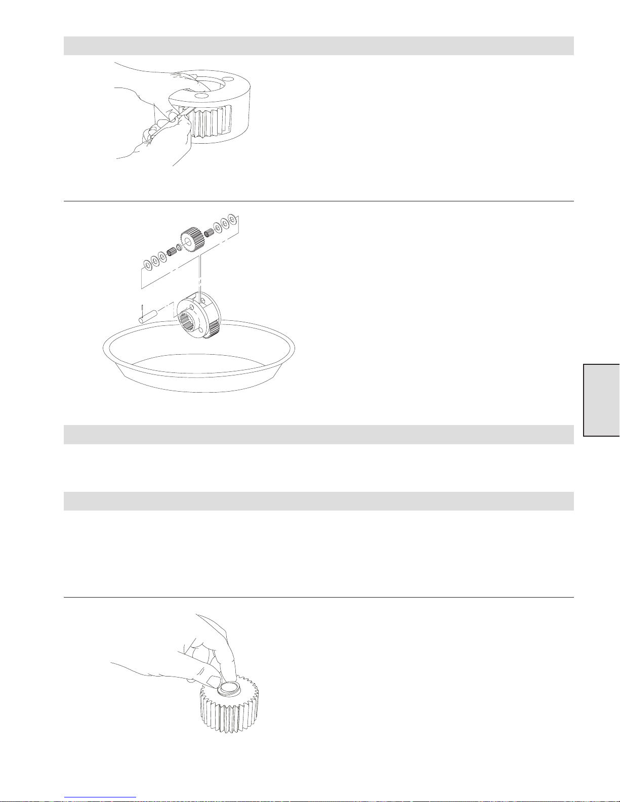
Intermediate Carrier Disassembly
(Dwg. MHP1169)
rior to disassembly check planet gear side clearance, 0.005 to 0.032
inches (0.13 to 0.81 mm). Spin gears, gears should rotate freely. If
gears are tight or clearance is incorrect, disassemble planet
assembly.
1. Tap roll pin (50) completely into intermediate planet pin (46).
2. Place carrier in a wide shallow container or on a clean shop
towel. Each gear contains 36 needle bearings (48) that may fall
out as the intermediate carrier is disassembled.
3. Tap out intermediate planet pin (46). Remove thrust washers
(52, 55, and 64), needle bearings (48), and spacer (49). Thrust
washers (52, 55, and 64) are used in combination to achieve
clearance, all three might not be present or quantities may
vary.
4. Tap roll pin (50) out of intermediate planet pin (46).
(Dwg. MHP1187)
Inspection
Intermediate Carrier Assembly
Section 5
1. Check all gear teeth for signs of galling, chipping, or uneven
wear pattern.
Cut two pieces of cardboard 3 inches (76 mm) square.
Make a intermediate planet pin tool as follows:
a. Cut an old pin to the same width as the gear, or
b. Make a pin that is the same diameter as intermediate planet
pin (46) and as long as the gear is wide.
1. Place planet gear (51) on the cardboard square and insert pin
tool.
2. Insert 5 to 7 needle bearings (48) into gear around pin tool,
ensure first few needle bearings do not tip over.
3. Insert spacer (49) followed by all 18 needle bearings.
(Dwg. MHP1164)
49
Page 50
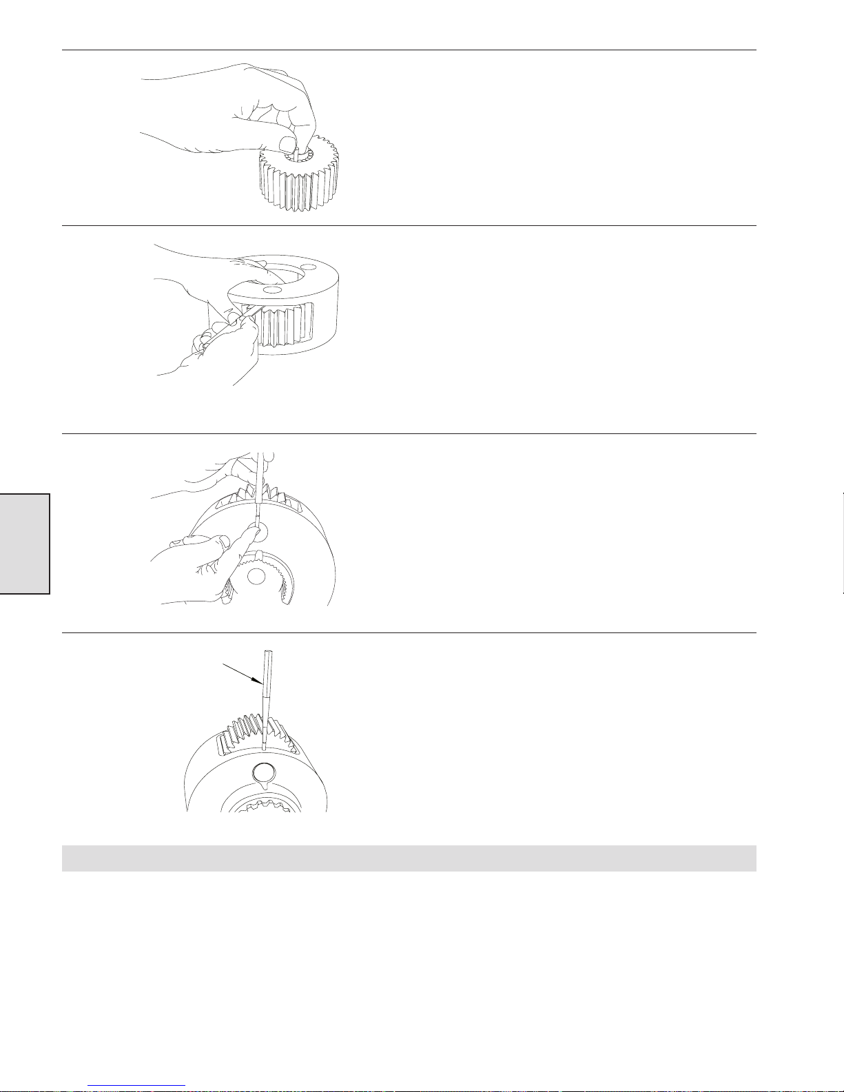
(Dwg. MHP1161)
(Dwg. MHP1169)
4. Place a thrust washer (either 52,55,or 64) on top of this
followed by the other cardboard square.
5. Pinching both cardboard squares, flip assembly over. Finish
inserting the remaining needle bearings.
6. Place another thrust washer on top of assembly. Carefully slide
assembly off the cardboard, pinching the thrust washers as they
come free. Slide this assembly right into the intermediate
carrier (47).
7. Align the bores and push out the pin tool using the
intermediate planet pin (46). Measure the side clearance and
adjust the thrust washers (52, 55, or 64) to provide 0.005 -
0.032 inches (0.13 - 0.81 mm). Spin gears, gears should rotate
freely.
8. Measure the distance that roll pin (50) must be tapped into
carrier so that the roll pin is half in the carrier and half in the
pin, and mark the punch.
Section 5
(Dwg. MHP1165)
(Dwg. MHP1166)
Output Carrier Assembly
Punch
9. Tap roll pin (50) into intermediate carrier (47) to the mark on
the punch.
Cut two pieces of cardboard 3 inches (76 mm) square.
Make an output planet pin tool as follows:
a. Cut an old pin to the same width as the gear, or
b. Make a pin that is the same diameter as output planet pin
(35) and as long as the gear is wide.
50
Page 51
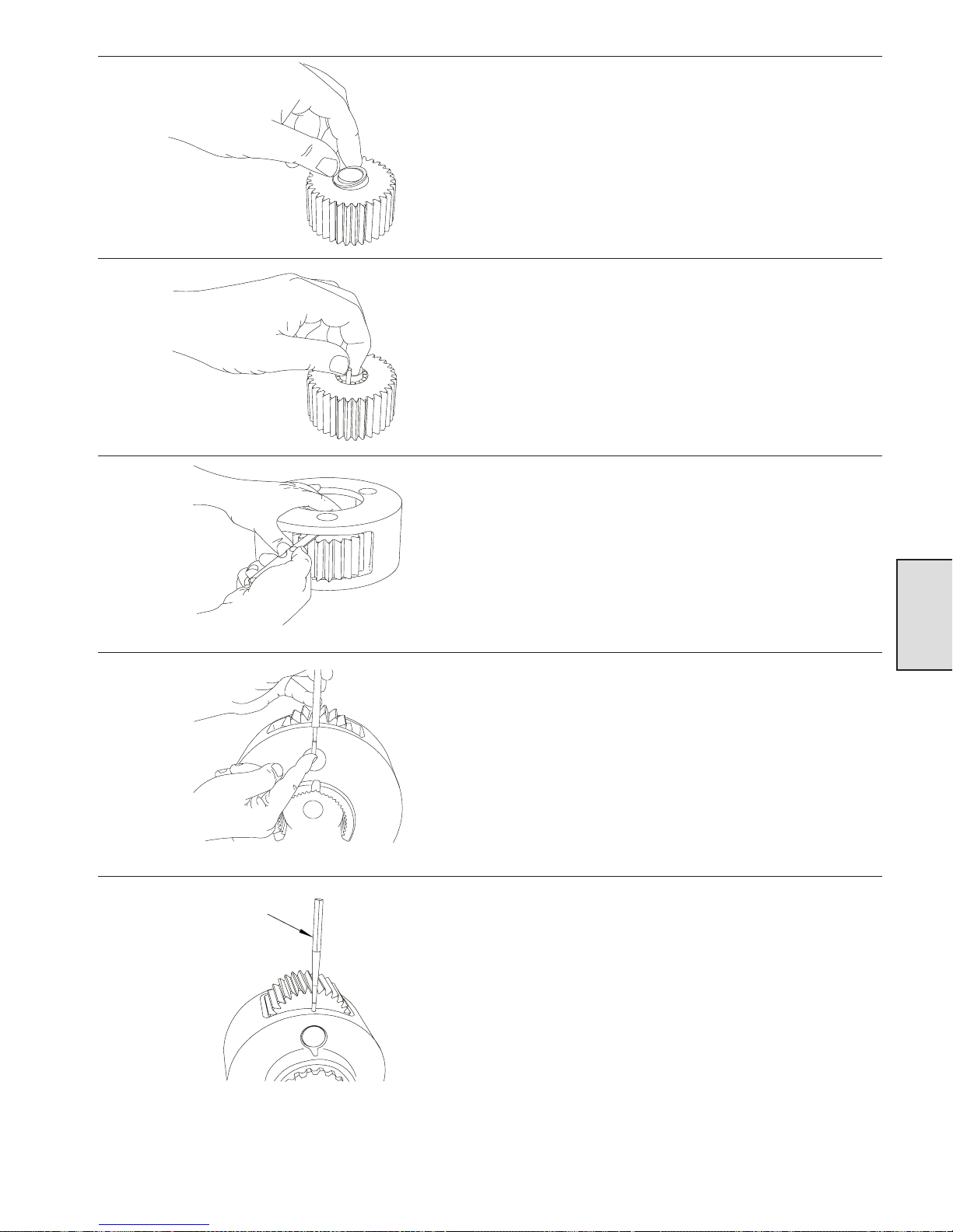
(Dwg. MHP1164)
(Dwg. MHP1161)
1. Place planet gear (39) on the cardboard square and insert pin
tool.
2. Insert 5 to 7 needle bearings (41) into gear around pin tool,
ensure first few needle bearings do not tip over.
3. Insert spacer (59) followed by all 24 needle bearings.
4. Place a thrush washer (either 34,40 or 42) on top of this
followed by another cardboard square.
5. Pinching both cardboard squares, flip assembly over. Finish
inserting the remaining needle bearings.
6. Place another thrust washer on top of assembly. Carefully slide
assembly right into the output carrier (37).
7. Align the bores and push out the pin tool using the output
planet pin (35). Measure the side clearance and adjust the
thrust washers (34, 40, or 42) to provide 0.005 - 0.032 inches
(0.13 - 0.81 mm). Spin gears, gears should rotate freely.
(Dwg. MHP1169)
(Dwg. MHP1165)
Punch
Section 5
8. Measure the distance that roll pin (38) must be tapped into
carrier so that the roll pin is half in the carrier and half in the
pin, and mark the punch.
9. Tap roll pin (38) into output carrier (37) to the mark on the
punch.
(Dwg. MHP1166)
51
Page 52
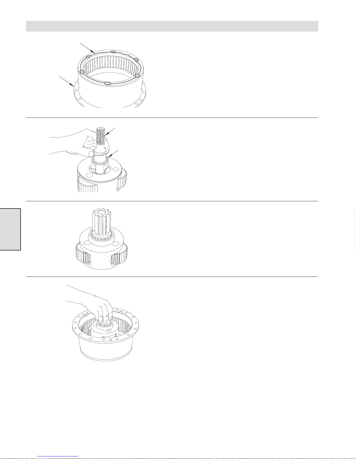
Reduction Gearbox Assembly
Loctite bead
Housing
(Dwg. MHP1162)
(Dwg. MHP1163)
®
1. Apply a bead of Loctite® 515 to the back mating surface of
housing (44).
2. Insert capscrews (68) through housing (69) and into housing
(44). Tighten capscrews to 60 ft lb (81 Nm).
3. Press bearing (67) into housing (69) followed by oil seal (71).
Intermediate
Sun Gear
4. Slide one thrust washer (65) onto input end of intermediate sun
gear (54) followed by thrust washer (63) and then next thrust
washer (65).
Thrust Washer
Section 5
(Dwg. MHP1170)
5. Place retainer ring (53) on end of output sun gear (45). Slide
this assembly into intermediate carrier assembly and fasten
with retainer ring (53).
6. Insert intermediate sun gear assembly into intermediate carrier
assembly, twisting until fully seated.
7. Lower this assembly into the housing assembly, twisting sun
gear or carrier assembly until assembly is fully seated.
(Dwg. MHP1160)
52
Page 53
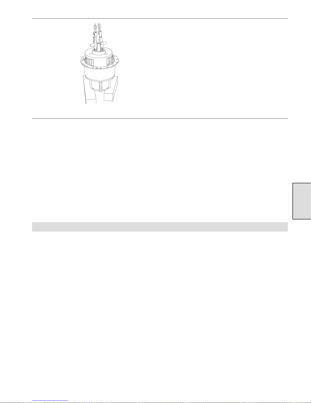
(Dwg. MHP11688)
8. Apply EP grease to the end of output sun gear (45). Set thrust
washer (43) in the grease and apply more to the top of the
thrust washer.
9. Lower intermediate carrier assembly into the housing
assembly, twisting carrier until carrier is fully seated.
10. Apply a bead of Loctite® 515 to the mating surface of the
drum.
11. Install two 1/2 - 13 x 1 inch eye bolts into housing assembly.
Lift and insert reduction gear assembly into drum. Reduction
gearbox assembly might have to be rotated to allow
intermediate sun gear to align with and slide into coupling
(73). Remove eye bolts.
®
12. Apply a bead of Loctite
(44).
13. Place thrust washer (36) inside of cover (33), use some EP
grease to hold in place.
14. Align the two threaded holes in cover (33) with the grooves in
housing (44).
15. Insert capscrews (32) through cover and into housing, tighten
to 60 ft lb (81 Nm).
515 to the mating surface of housing
Section 5
Winch Assembly
1. Press bearing (30) and oil seal (29) into outboard upright (26).
2. Slide upright onto cover (33).
3. Insert output shaft (28) through upright and into reduction
assembly. Upright might have to be rotated to allow output
shaft to align with splines in reduction gearbox and teeth in
upright.
4. Insert capscrews (86) through sideframe (78), into corner bar
(20) and tighten to 75 ft lb (102 Nm).
5. For units with disc brake refer to Disc Brake Section.
6. Insert capscrew (2) through cover (4) and gasket (19). Install
this assembly on upright and tighten to 18 ft lb (24 Nm).
7. Install mounting bolts.
8. Fill reduction gearbox with lubricant.
53
Page 54
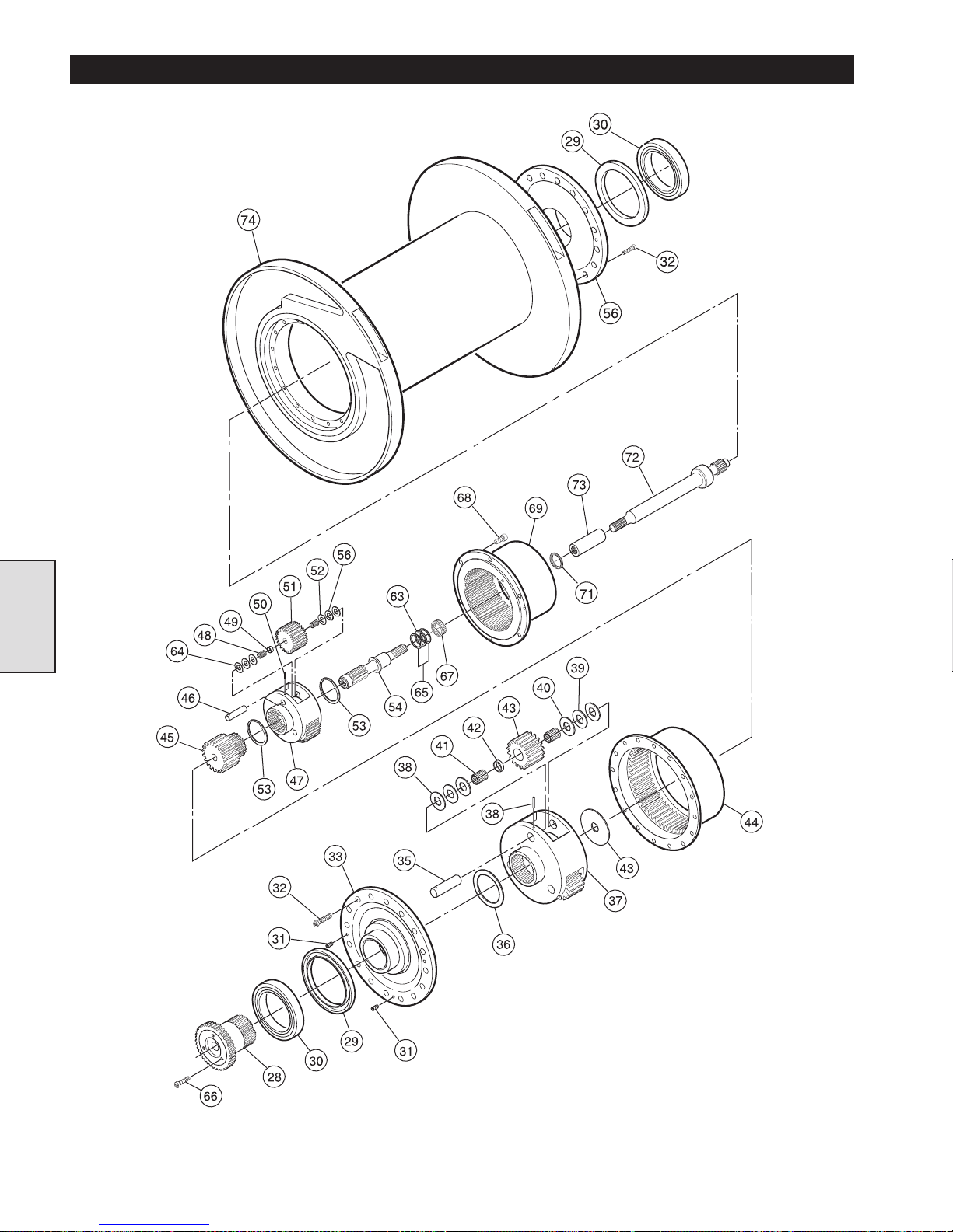
REDUCTION GEAR ASSEMBLY PARTS DRAWING
Section 5
(Dwg. MHP1221)
54
Page 55
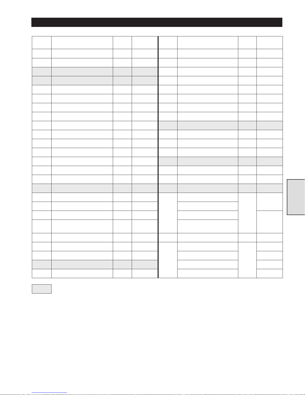
REDUCTION GEAR ASSEMBLY PARTS LIST
ITEM
NO.
DESCRIPTION
OF PART
QTY
TOTAL
PA RT
NUMBER
ITEM
NO.
DESCRIPTION
OF PART
QTY
TOTAL
PA RT
NUMBER
28 Output Shaft 1 21019 50 Pin. Roll 3 71267793
--- Gearbox Assembly (1) 1 23900 51 Gear, Intermediate Planet 3 23899
•
29 Oil Seal 2 71053862 52 Thrust Washer 6 71113260
•
30 Bearing 2 71053854 53 Retainer Ring 2 71113278
31 Plug, Drain 2 71267561 54 Intermediate Sun Gear 1 23896
32 Capscrew 16 71264683 55 Thrust Washer 6 71113229
33 End Cover 1 20393-1 56 End Cover 1 24440
--- Output Carrier Assembly (2) 1 23891 59 Spacer 3 20388
34 Thrust Washer 6 71146815
•
63 Bearing, Thrust 1 71113195
35 Pin, Output Planet 3 20394 64 Thrust Washer 6 71146807
36 Thrust Washer 1 23738 65 Thrust Washer 2 71113203
37 Output Carrier 1 23892 66 Capscrew 3 71266936
38 Pin, Roll 3 71113302
•
67 Bearing, Needle 1 71113187
39 Gear Output Planet 3 23893 68 Capscrew 6 71113161
40 Thrust Washer 6 71126478 69 Housing 1 20672
•
41 Bearing, Roller 126 71113286
•
71 Oil Seal 1 71113179
42 Thrust Washer 6 50533
72
Drive Shaft (12 inch)
1
24035
43 Thrust Washer 1 20406 Drive Shaft (15 inch)
44 Housing 1 20377 Drive Shaft (24 inch)
23902
---
Intermediate Carrier
Assembly (3)
1 23897 Drive Shaft (27 inches)
45 Output Sun Gear 1 23894 73 Coupling 1 50775
46 Pin, Intermediate Planet 3 20386
74
Drum Assembly (12 inch)
1
23750
47 Intermediate Carrier 1 23898 Drum Assembly (15 inch) 24033
•
48 Bearing, Needle 108 71113252 Drum Assembly (24 inch) 21729
49 Spacer 3 20389 Drum Assembly (27 inch) 24030
•
Recommended spare.
(1)
Gearbox Assembly includes items 31, 33, 36, 44, 63, 65, 67 through 69, 71, Output Carrier Assembly and
Intermediate Carrier Assembly.
(2) Output Carrier Assembly includes items 34, 35, and 37 through 43 and 59.
(3) Intermediate Carrier Assembly includes items 45 through 55 and 64.
Section 5
55
Page 56

PARTS ORDERING INFORMATION
The use of replacement parts other than Ingersoll-Rand
Material Handling may invalidate the Company’s warranty. For
prompt service and genuine Ingersoll-Rand Material Handling
parts, provide your nearest Distributor with the following:
1. Complete winch model number as it appears on the
nameplate.
2. Part number and part description as shown in the service
manual.
3. Quantity required.
Return Goods Policy
If it becomes necessary to return the complete winch or certain
parts to the factory, contact the Distributor from whom you
purchased the winch, or the nearest Ingersoll-Rand Distributor
in your locality.
Ingersoll-Rand will not accept any returned goods for warranty
or service work unless prior arrangements have been made and
written authorization has been provided from the location where
the goods were purchased.
NOTICE
Continuing improvement and advancement of design
may cause changes to this winch which are not
included in this manual. Manuals are periodically
revised to incorporate changes. Always check the
manual edition number on the front cover for the
latest issue.
Disposal
When the life of the winch has expired, it is recommended that
the winch be disassembled, degreased and parts separated as to
materials so that they may be recycled.
For additional information contact:
Ingersoll-Rand Material Handling
P.O. Box 24046
2724 Sixth Avenue South
Seattle, WA 98124-0046
Phone: (206) 624-0466
Fax: (206) 624-6265
or
Ingersoll-Rand Material Handling
Douai Operations
111, avenue Roger Salengro
59450 Sin Le Noble, France
Phone: (33) 3-27-93-08-08
Fax: (33) 3-27-93-08-00
56
Page 57

SERVICE NOTES
57
Page 58

SERVICE NOTES
58
Page 59

SERVICE NOTES
59
Page 60

United States Office Locations International Office Locations
For Order Entry,
Order Status and
Technical Support
Ingersoll-Rand
Material Handling
P.O. Box 24046
2724 Sixth Avenue South
Seattle, WA 98124-0046
Phone: (206) 624-0466
Fax: (206) 624-6265
Regional Sales Offices
Chicago, IL
888 Inadustrial Drive
Elmhurst, IL 60126
Phone: (630) 530-3800
Fax: (630) 530-3891
Detroit, MI
23192 Commerce Drive
Farmington Hills, MI 48335
Phone: (810) 476-6677
Fax: (810) 476-6670
Houston, TX
Suite 150
2500 East T.C. Jester
Houston, TX 77008
Phone: (713) 864-3700
Fax: (713) 864-2244
Los Angeles, CA
11909 E. Telegraph Road
Santa Fe Springs, CA 90670
Phone: (310) 948-4189
Fax: (310) 948-1828
Philadelphia, PA
P.O. Box 425
900 E. 8th Ave., Suite 103
King of Prussia, PA 19406
Phone: (610) 337-5930
Fax: (610) 337-5912
Offices and distributors in
principal cities throughout the
world. Contact the nearest
Ingersoll-Rand office for the
name and address of the
distributor in your country or
write/fax to:
Ingersoll-Rand
Material Handling
P.O. Box 24046
2724 Sixth Avenue South
Seattle, WA 98124-0046
Phone: (206) 624-0466
Fax: (206) 624-6265
Canada
National Sales Office
Regional Warehouse
Toronto, Ontario
51 Worcester Road
Rexdale, Ontario
M9W 4K2
Phone: (416) 213-4500
Fax: (416) 213-4510
Order Desk
Fax: (416) 213-4506
Regional Sales Offices
Calgary, Alberta
44 Harley Road S.E.
Calgary, Alberta
T2V 3K3
Phone: (403) 252-4180
Fax: (403) 252-4462
Edmonton, Alberta
1430 Weber Center
5555 Calgary Trail N.W.
Edmonton, Alberta
T6H 5G8
Phone: (403) 438-5039
Fax: (403) 437-3145
British Columbia
201-6351 Westminster Hwy
Richmond, B. C.
V7C 5C7
Phone: (604) 278-0459
Fax: (604) 278-1254
Latin America Operations
Ingersoll-Rand
Production Equipment Group
730 N.W. 107 Avenue, Suite 300
Miami, FL 33172-3107 USA
Phone: (305) 559-0500
Fax: (305) 559-7505
Europe, Middle East and Africa
Ingersoll-Rand Material Handling
Douai Operations
111, avenue Roger Salengro
59450 Sin Le Noble, France
Phone: (33) 3-27-93-08-08
Fax: (33) 3-27-93-08-00
Asia Pacific Operations
Ingersoll-Rand (Japan) Ltd.
Shin-Yokohama Square Bldg.
(5th Floor)
2-3-12 Shin-Yokohama,
Kouhoku-Ku,
Yokohama-shi, Kanagawa
Pref. 222 Japan
Phone: 81-45-476-7800
Fax: 81-45-476-7806
Russia
Ingersoll-Rand Company
World Trade Center
Office 1101
Krasnopresnenskaya Nab. 12
Moscow, Russia 123610
Printed in USA
Montreal, Quebec
3501 St. Charles Blvd.
Kirkland, Quebec
H9H 4S3
Phone: (514) 695-9040
Fax: (514) 695-0963
 Loading...