

Page 1
DIRECT EXPANSION COMPRESSED AIR DRYERS
EN -
-
-
FR -
Operators Manual
SECHEUR D’AIR A EXPANSION DIRECTE
Manuel des Opérateurs
D25IT D42IT D60IT
102IT D140IT D170IT
D
115/1/60
Cod. 710.0134.39.00 Rev1B – 01.2009
Page 2

Page 3
-
EN -
CONTENTS
1. GENERAL INFORMATION
1.1 Functional Description 4
1.2 Safe Use of the Dryer 4
2. INSTALLATION
2.1
2.2 Installation Site 5
2.3 Installation 5
3. START UP
3.1 Control Panel 6
3.1.1 Keys function 7
3.1.2 Condensate discharge Parameters
Programming 7
3.1.3 Anomaly Warning 8
3.1.4 Remote signalling Alarm 8
3.2 Before Start Up 9
3.3 Start Up 9
Acceptance and Transportation 5
-
FR --
R
TABLE DES MATIERES
1. INFORMATIONS GENERALES
1.1 Description fonctionnelle 13
1.2 Utilisation du séchoir en toute sécurité 13
2. INSTALLATION
Réception et transport 14
2.1
2.2 Lieu d'installation 14
2.3 Installation 14
3. MISE EN SERVICE
3.1 Pupitre de commande 15
3.1.1 Fonction des touches 16
3.1.2 Programmation des paramètres 16
3.1.3 Signalisation des anomalies 17
3.1.4 Signalisation d’alarme a distance 17
3.2 Opérations préliminaires à la mise en marche 18
3.3 Mise en marche 18
4. MAINTENANCE, TROUBLESHOOTING
AND DISMANTLING
4.1 Maintenance 9
4.2 Troubleshooting 9
4.3 Dismantling 11
TTACHMENTS TO THIS MANUAL
A
A) Air and Refrigeration Circuit 22
B) Electric Circuit Diagram 23
C) Technical Data Sheet 24
D) Correction Factors 25
E) Dryer Dimensions 26
F) Basic Spare Parts 27
4. ENTRETIEN, RECHERCHE DES PANNES ET
DEMANTELEMENT
4.1 Entretien 18
4.2 Recherche des pannes 18
4.3 Démantèlement 20
NNEXES AU MANUEL
A
A) Circuit air et frigo 22
B) Schéma électrique 23
C) Caractéristiques Techniques 24
D) Facteurs De Correction 25
E) Dimensions Du Sécheur 26
F) Pièces De Rechange Essentielles 27
Cod. 710.0134.39.00 Rev1B – 01.2009
2
- 29
Page 4
EN -
-
INTRODUCTION
This manual is an integral part of the dryer you bought, and must remain with the machine even if this will be resold.
It is highly recommended that the qualified*personnel for installation maintenance and/or control will fully comply with the
contents of this manual and the prevention and safety rules in force in the country where the system will be used. In this way,
not only the usage of the machine will be rational, but also the service will result cost effective.
In case your dryer will present any kind of problem, please contact your local authorized Ingersoll Rand distributor.
Please note that, when necessary, the use of original spare parts will ensure efficiency and long duration to your dryer.
Due to the continuous technological evolution, Ingersoll Rand reserves the right to modify the specifications contained in this
manual without giving previous notice.
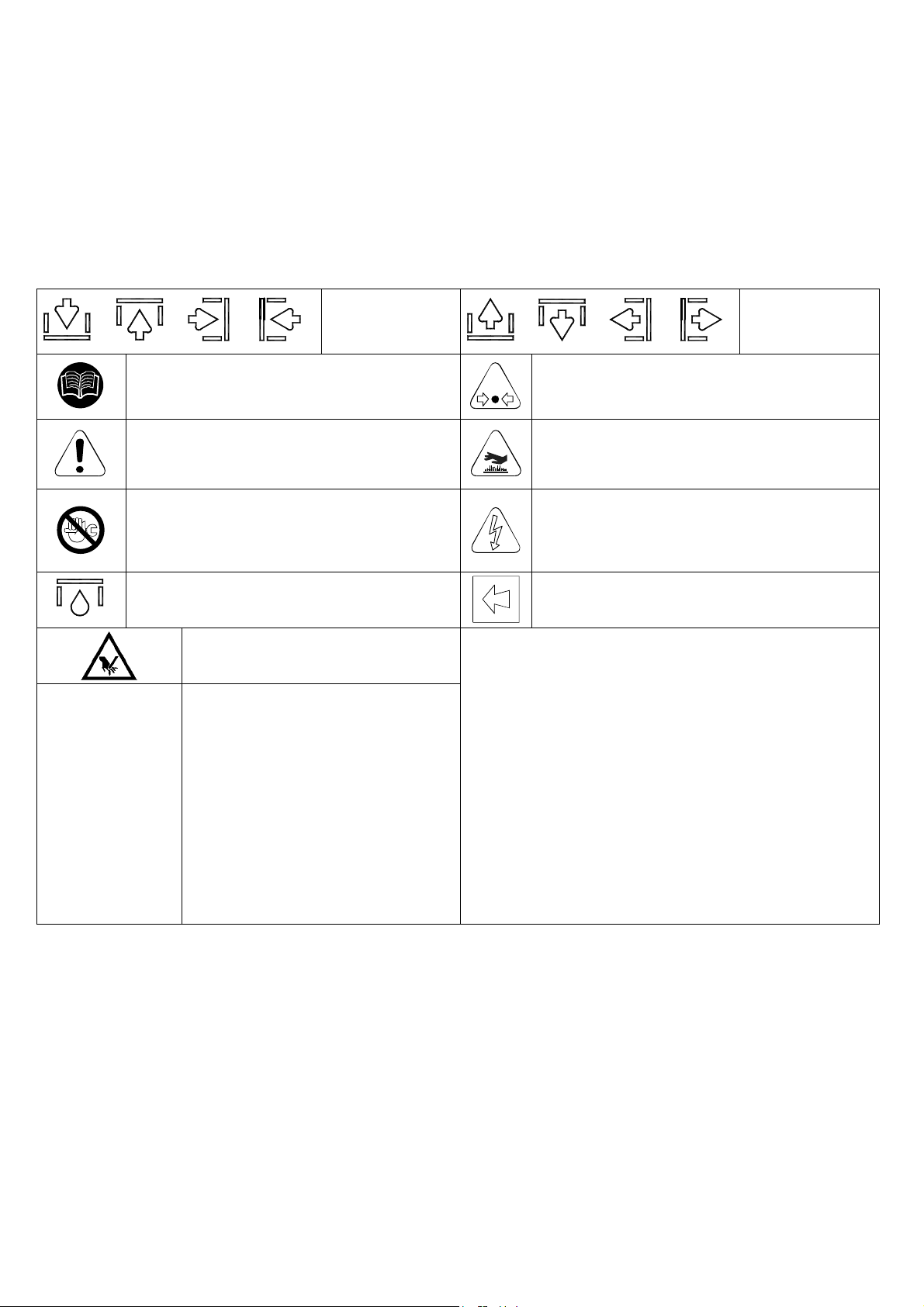
SYMBOLS USED IN THE MANUAL AND ON THE DRYER
or or or
Read the Operators manual before attempt to
start up the machine and to perform any
service operation on the dryer.
Pay particular attention to the indications
preceded by these symbols.
Installation, maintenance, and/or control
operations preceded by these symbols must
be performed exclusively by qualified
personnel*.
Condensate drain point.
Pay particular attention to the risk of
moving parts
Attention: Before performing any
maintenance operation on this
machine, do not forget to disconnect
the electric supply, to completely
discharge air pressure, and to refer to
the Operators manual
Air inlet.
or or or
Pay particular attention to components or
systems under pressure.
Pay particular attention to hot surfaces.
Pay particular attention to the risk of electric
shock.
Rotation direction of the fan.
Air outlet.
* Qualified personnel must be trained and certified in accordance with local laws and regulations.
WARRANTY
The Company warrants that the equipment manufactured by it and delivered hereunder will be free of defects in material and
workmanship for a period of twelve months from the date of placing the Equipment in operation or eighteen months from the
date of shipment from the factory, whichever shall first occur. The Purchaser shall be obligated to promptly report any failure to
conform to this warranty, in writing to the Company in said period, whereupon the Company shall, at its option, correct such
nonconformity, by suitable repair to such equipment or, furnish a replacement part F.O.B. point of shipment, provided the
Purchaser has stored, installed, maintained and operated such Equipment in accordance with good industry practices and has
complied with specific recommendations of the Company. Accessories or equipment furnished by the Company, but
manufactured by others, shall carry whatever warranty the manufacturers have conveyed to the Company and which can be
passed on to the Purchaser. The Company shall not be liable for any repairs, replacements, or adjustments to the Equipment or
any costs of labor performed by the Purchaser or others without Company's prior written approval.
The effects of corrosion, erosion and normal wear and tear are specifically excluded. Performance warranties are limited to
those specifically stated within the Company's proposal. Unless responsibility for meeting such performance warranties are
limited to specified tests, the Company's obligation shall be to correct in the manner and for the period of time provided above.
THE COMPANY MAKES NO OTHER WARRANTY OR REPRESENTATION OF ANY KIND WHATSOEVER, EXPRESSED
OR IMPLIED, EXCEPT THAT OF TITLE, AND ALL IMPLIED WARRANTIES OF MERCHANTABILITY AND FITNESS FOR A
PARTICULAR PURPOSE, ARE HERBY DISCLAIMED.
Cod. 710.0134.39.00 Rev1B – 01.2009
3
- 29
Page 5
Correction by the Company of nonconformities whether patent or latent, in the manner and for the period of time provided
above, shall constitute fulfillment of all liabilities of the Company for such nonconformities whether based on contract, warranty
negligence, indemnity, strict liability or otherwise with respect to or arising out of such Equipment.
The Purchaser shall not operate Equipment which is considered to be defective, without first notifying the Company in writing
of its intention to do so. Any such use of Equipment will be at Purchaser's sole risk and liability.
Note that this is Ingersoll Rand standard warranty. Any warranty in force at the time of purchase of the equipment or
negotiated as part of the purchase order may take precedence over this warranty.
1. GENERAL INFORMATION
1.1 FUNCTIONAL DESCRIPTION
Ingersoll Rand refrigerated air dryers remove moisture from compressed air. Moisture is detrimental to pneumatically
operated appliances, controls, instruments, machinery and tools.
High temperature compressed air enters the dryer and it is cooled down by the internal integrated air/air aftercooler.
Then a filter/separator removes solid particles and condensate liquid before entering the aluminum heat exchanger where
the air is cooled down to the dew point temperature in two different stages: In the first air/air sector compressed inlet air is
cooled thanks to the colder compressed air coming out counterflow from the condensate separator. In the second
refrigerant / air sector, compressed air temperature is further lowered to the dew point temperature. During this two stages
almost all the oil and water vapours contained in compressed air are condensed to liquid and successively be separated
from the compressed air in the condensate separator and drained out by the automatic drain. At this point the obtained
cold air re-enters counterflow the initial air / air exchanger and it is reheated by the inlet hot air with the consequence of
energy recovering and also reduction of the relative humidity contained in the outflowing air.
This dryer can be easily installed into various pneumatic systems in which dry air is required or desired. Please refer to
Start up chapter for complete operating details.
The dryer comes provided with all the control, safety and adjustment devices, therefore no auxiliary devices
are needed.
A system overload not exceeding the maximum operative limits can worsen the operational performance of the
dryer (high dew point), but it will not affect its safety.
The electric diagram (attachment B) shows the minimum protection degree IP 42.
Improper grounding can result in electrical shock and can cause severe injury or death.
This product must be connected to a grounded, metallic, permanent wiring system or an equipment-grounding
terminal or lead on the product.
All grounding must be performed by a qualified electrician and comply with national and local electrical codes.
In the event of an electrical short circuit, grounding reduces the risk of electric shock by providing an escape
wire for the electric current.
Ground must be established with a bare grounding wire sized according to the voltage and minimum branch
circuit requirements.
Ensure good bare metal contact at all grounding connection points, and ensure all connections are clean and
tight.
Check grounding connections after initial installation and periodically thereafter to ensure good contact and
continuity has been maintained.
Check with a qualified electrician or service technician if the grounding instructions are not completely
understood, or if in doubt as to whether the product is properly grounded.
1.2 USE OF THE MACHINE IN SAFE CONDITIONS
This system has been designed and manufactured in compliance with the European safety directive in force and
UL/ULC, therefore any installation, use and maintenance operations must be performed respecting the instructions
contained in this manual.
Because an air dryer is pressurized and contains rotating parts, the same precautions should be observed as with any
piece of machinery of this type where carelessness in operation or maintenance could be hazardous to personnel. In
addition to obvious safety rules that should be followed with this type of machinery, safety precautions as listed below
must be observed
1. Only qualified personnel shall be permitted to adjust, perform maintenance or repair this air dryer.
2. Read all instructions completely before operating unit.
3. Pull main electrical disconnect switch and disconnect any separate control lines, if used, before
attempting to work or perform maintenance on the unit.
4. Do not attempt to service any part while machine is in an operational mode.
5. Do not attempt to remove any parts without first relieving the entire air system of pressure.
6. Do not attempt to remove any part of the refrigeration system without removing and containing
refrigerant in accordance with the EPA and local regulations.
7. Do not operate the dryer at pressures in excess of its rating.
8. Do not operate the dryer without guards, shields and screen in place.
9. Inspect unit daily to observe and correct any unsafe operating conditions.
Cod. 710.0134.39.00 Rev1B – 01.2009
4 - 29
Page 6
2. INSTALLATION
2.1 ACCEPTANCE, UNPACKING AND HANDLING
Upon receiving your Ingersoll Rand air dryer, please inspect the unit closely. If rough handling is detected, please note
it on your delivery receipt, especially if the dryer will not be uncrated immediately. Obtaining the delivery person's signed
agreement to any noted damages will facilitate any insurance claims by the customer.
It is mandatory to keep the dryer always in vertical position, as indicated by the symbols present on the packaging. For
handling, use devices having sufficient capacity for the weight of the machine.
Remove the packaging after having positioned the dryer in the installation site. Dispose the various packaging
materials in compliance with the relevant rules locally in force.
If not in use, the dryer can be stored in its packaging in a dust free and protected site between 32°F (0°C) and 120 °F
(50 °C), and a specific humidity not exceeding 90 %. Should the stocking time exceed 12 months, please contact your
local Ingersoll Rand authorized distributor.
Under no circumstances should any person attempt to lift heavy objects without proper lifting equipment (i.e., crane,
hoist, slings or fork truck). Lifting any unit without proper lifting equipment, may cause serious injury. Use fork lift channels
where provided.
2.2 INSTALLATION SITE
While preparing a proper site for the installation of the dryer, please take into account the following
requirements
The machine must be protected from atmospheric agents and not directly exposed to sun light.
A seating base flat and capable to hold the weight of the machine.
Ambient temperature complying with the nominal data of the dryer.
The dryer should be located in a clean area, without forced air draft that can affect the fan control
system.
Make sure to leave sufficient clearance (20 inches, 500 mm) around the dryer in order to allow an
adequate cooling of the machine and for maintenance and/or control operations.
The incoming air must be free from smoke or flammable vapours which could lead to explosion or fire risks.
2.3 INSTALLATION
Before attempting any installation operation, make sure that
No parts of the air system are under pressure.
No parts of the system are electrically powered.
Tubing to be connected to the dryer are free of impurities.
All interconnecting piping has been tightened.
After having verified the points listed above, you can proceed to the installation of the machine.
1. Connect the dryer to the compressed air lines. If not already existing, we suggest to install a by-pass
allowing to isolate the machine from the plant, thus to facilitate eventual maintenance operations.
2. Perform the electrical connection in accordance with any local laws and regulations after reviewing
the dryer electrical specifications and wiring diagram.
3. Check the condensate drainage assembly, and connect the drain flexible hose to the draining line,
keeping in mind that the condensate separated by the dryer may contain oil, therefore, in order
to dispose of it in compliance with the local rules in force, we suggest installing a water-oil
separator having adequate capacity.
4. Power the dryer after having checked that the nominal voltage and line frequency are constant and
matching the nominal values of the machine. The user must provide the installation with an
adequate line protection and a ground terminal complying with the electrical rules locally in
force.
In order to optimise the use of the dryer, we suggest to place it in such a way that all the control instruments
of the machine will result easily visible.
A suitably sized prefilter must be installed before the dryer. Failure to install and maintain a proper
prefilter will void the dryer warranty. The rating for this filter must be at least 10 micron.
Please note that inside the unit is already mounted a 1 micron filter
Cod. 710.0134.39.00 Rev1B – 01.2009
5 - 29
Page 7
3. START UP
Ensure that the dryer is by−passed, or there is no load on the cooler.
Switch on the main electrical isolation switch (if present). The control panel will show the message OFF, indicating that the
line and control voltages are available.
Start sequence
The dryer will initially start by pressing the local ON/OFF button for 1 second. The start sequence will progress only if there
are no active alarms. The compressor motor will start AFTER 120 SECONDS. The fan motor will start simultaneously with
the compressor for D300-360IN models, after 30 seconds for smaller models.
Stop sequence
The dryer can be stopped locally from the control panel. After having pressed the ON/OFF switch for 1 second, the
compressor and the fan motor keep on running for further 10 seconds in order to re-balance the internal pressures. The
dryer can be also stopped due to an alarm or energy saving condition (ESA or ES2). Any alarm will de−energize the
compressor, fan motor can still running, it depends on the type of alarm (see Display indications chapter). If the shutdown is
due to an alarm, a message will blink on display indicating the reason for the shutdown. Energy saving condition (ESA or
ES2) occurs when the dew point stands below the set value for a long time in order to save energy and avoid heat
exchanger freezing. This situation can happen when ambient temperature is low and there is no compressed air load.
Variable speed fan control
A patented microprocessor allows to adjust dryer’s cooling capacity by changing the fan motor speed. If the dew point is
greater than the set value, the fan speed is increased, if the dew point is smaller than the set value, the fan velocity is
decreased. The range can be from 0 to 100% and the higher is the fan speed, the faster the fan LED blinks, you can read
the exact value by pressing the UP button. If the velocity is 100% you will read FL (Full Load). Under load standard
condition the fan speed is usually at 100%, if there is no load the fan velocity can oscillate between 0 and 20%.
In models D300-360IN, in order to adjust the greater dryer’s cooling capacity, a hot gas by-pass valve cooperates with the
variable speed system.
3.1 CONTROL PANEL
The dryers are provided with an electronic control system. All adjustments and resets can be performed by means of the
digital panel located on the front of the dryer.
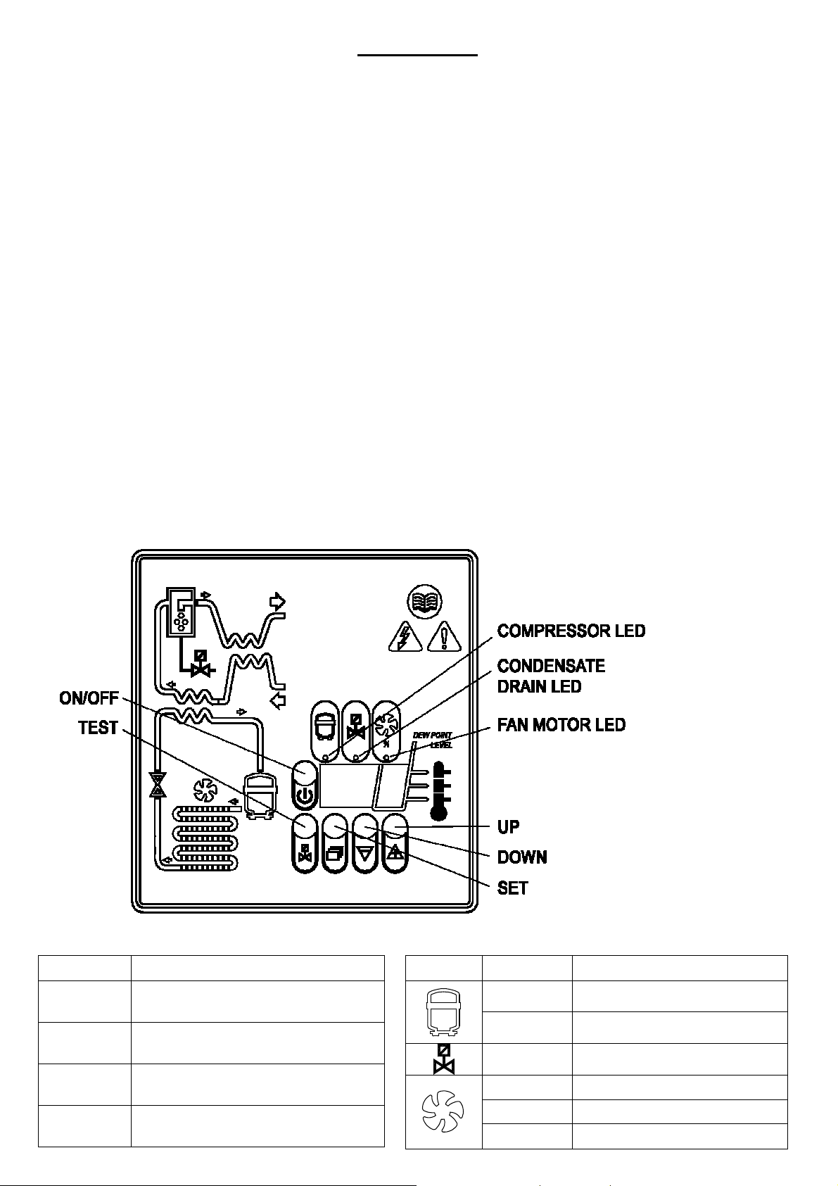
The control panel is composed of 5 keys (ON/OFF, TEST, SET, DOWN and UP) and a 3 digit display, with three
signalling LEDs indicated by icons (PIC 1)
DISPLAY VISUALIZATION AND SIGNALLING LEDS
DISPLAY DESCRIPTION
Cod. 710.0134.39.00 Rev1B – 01.2009
the unit is ON with low load
the unit is ON with normal load
the unit is ON with normal-high load
the unit is ON with high load
6 - 29
PIC. 1
LED STATUS DESCRIPTION
ON
Blinking
ON
ON
Blinking
OFF
Compressor energized
Programming mode activated
Condensate drain energized
Speed of the fan = 100%
Speed of the fan < 100%
Fan not running
Page 8
TEST:
3.1.1 KEYS FUNCTION
SET: When pushed and released during normal operation, it displays the dew point set value (decimal).
When pushed for 10 seconds, it allows to enter the C8 and C9 condensate drain parameters programming
menu (see relevant table).
When pushed after having set new configuration values, it stores the applied modifications.
When pushed for 3 sec. during normal operation, it activates the condensate drain.
DOWN: When pushed while setting the drain set point, it decreases the displayed value of one unit per
second, during the first 10 seconds, than of one unit every 0,1 sec.
When pushed for 10 seconds during normal operation, it starts an automatic test cycle of the controller.
UP: When pushed while setting the drain set point, it increases the displayed value of one unit per second,
during the first 10 seconds, than of one unit every 0,1 sec.
ON / OFF: Pushed for 1 second, it activates or deactivates the dryer. When the dryer is deactivated, the
display shows OFF.
NOTE: when the controller is in the OFF position, some parts of the dryer may still be energized. Therefore, for
safety purposes, disconnect the electrical power before performing any operation on the machine.
3.1.2 CONDENSATE DISCHARGE PARAMETERS PROGRAMMING
Push the SET key for 10 seconds to enter the parameters configuration menu: the display will show in
sequence the set point value, the code of the first modifiable parameter (C8) and its value).
Only if strictly necessary, use the UP and/or DOWN keys to change the displayed parameter value.
Press the SET key to store the previously changed parameter value or to browse the parameters without
changing them.
15 seconds after the last performed operation, the controller will return automatically to the normal
operation mode.
PARAMETER
DESCRIPTION
RANGE DEFAULT SET VALUE
C8
Delay between condensate
discharges
1 ÷ 999 (min)
1
C9
Time required for condensate
discharge
1 ÷ 999 (sec)
D25-60IT D102-170IT
2 3
NOTE: Changes entered for timing values will be effective only after exiting the programming, while changes to
other variables will be immediately effective.
Please remember that eventual changes to the configuration parameters of the machine could negatively affect
its efficiency. Thus, changes have to be performed by a person familiar with the operation of the dryer.
WARNING FOR USER:
IT’S FORBIDDEN TO ATTEMPT TO MODIFY THE OTHER CONFIGURATION PARAMETERS OF THE
ELECTRONIC CONTROLLER WITHOUT AUTHORIZATION AND COLLABORATION OF INGERSOLL RAND’S
AUTHORIZED DISTRIBUTOR.
Cod. 710.0134.39.00 Rev1B – 01.2009
7 - 29
Page 9
3.1.3 DISPLAY INDICATIONS
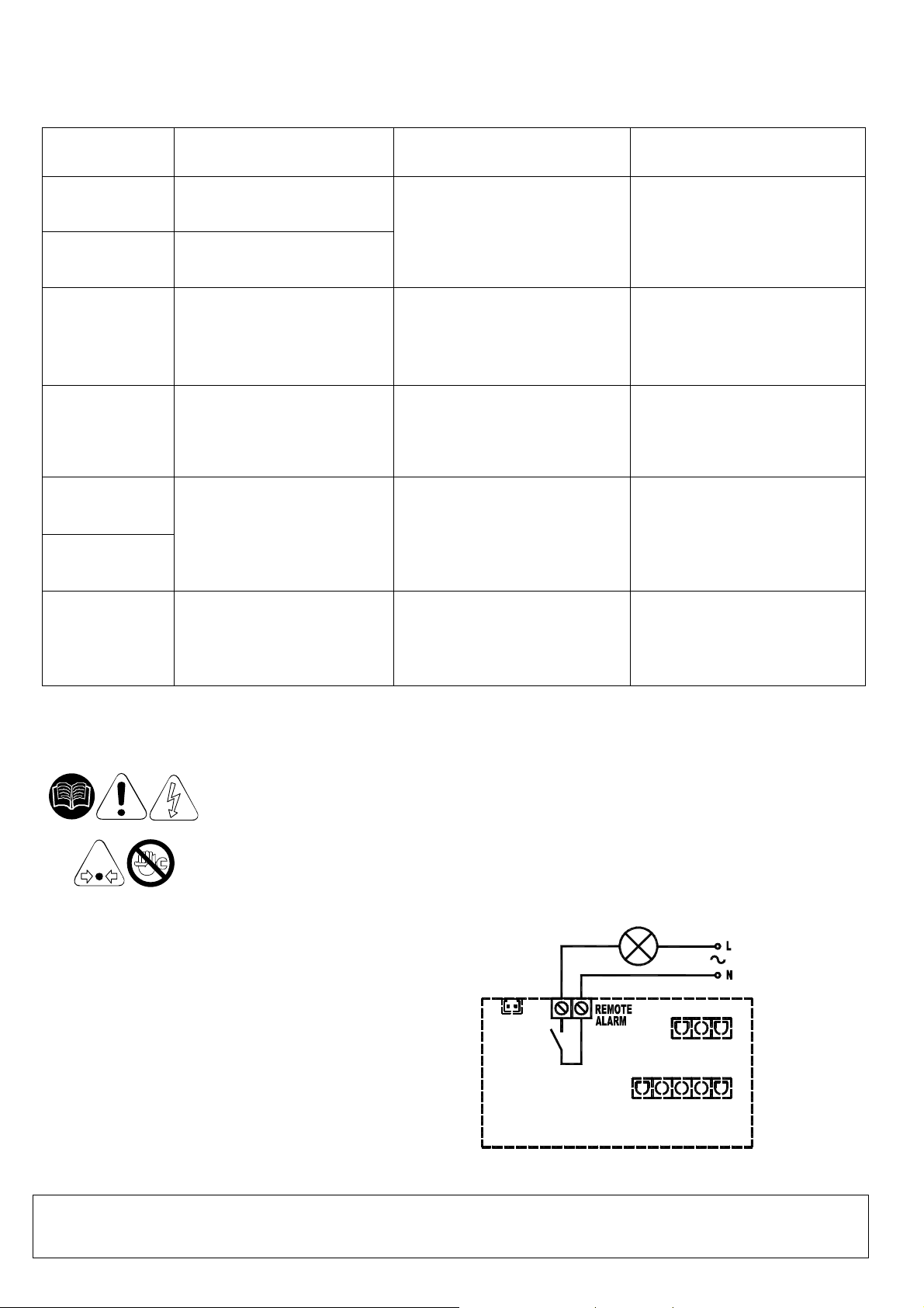
The controller is capable of recognizing certain types of anomalies in the drying circuit. In such cases, a message will
blink on the display, alternated to the current dew point value.
MESSAGE
(BLINKING)
CAUSE OUTPUTS ACTIONS
HtA
Ht2
LtA
PF1
ESA
ES2
ASt
Note: PF1 has priority on all other messages.
High dew point value
(delayed alarm)
Very high dew point value
(immediate alarm)
Low dew point value
Interruption or short circuit on
the PTC probe input line
The automatic Energy saving
mode activated due to low
load
Activated after repeated
alarms
3.1.4 REMOTE SIGNALING ALARM
The dryer control board is equipped with a dry contact for a remote alarm signal. This is
normally open contact: when an alarm is detected, this contact is closed.
Proceed as follows to activate a remote alarm output:
1. The User must review the diagram below.
2. Disconnect the dryer from electrical power supply, remove cover and left side panel.
3. Connect the alarm circuit to the terminal blocks (See PIC.2).
4. Replace cover, left side panel and reconnect power.
Alarm output ON
Refrig. Compressor output OFF
Fan output ON
Drain cycle standard
Alarm output ON
Refrig. Compressor output OFF
Fan output OFF
Drain cycle standard
Alarm output ON
Refrig. Compressor output OFF
Fan output OFF
Drain cycle standard
Alarm output OFF
Refrig. Compressor output OFF
Fan output OFF
Drain cycle standard
Alarm output ON
Refrig. Compressor output OFF
Fan output ON
Drain cycle standard
Resettable by switching off the
dryer.
If problem persists call your
local Ingersoll Rand distributor.
Automatic reset when dew
point returns to preset range.
If problem persists call your
local Ingersoll Rand distributor.
Resettable by switching off the
dryer. May require replacing the
faulty probe.
If problem persists call your
local Ingersoll Rand distributor.
No action necessary.
Automatic Reset
Call your local Ingersoll Rand
distributor.
Alarm Output relays electric
features:
Max. 250VAC / 3A – AC 15 (Amp. Inductive)
PIC.2
The activation of the above function is at the User’s discretion. The User will purchase all necessary
installation material. Any operation which needs access to the dryer must be carried out by qualified
personnel.
Cod. 710.0134.39.00 Rev1B – 01.2009
8 - 29
Page 10
3.2 BEFORE START UP
Before starting the machine, make sure that all operating parameters correspond to the nominal data.
The dryer is supplied already tested and preset for normal operation, and it doesn’t require any calibration.
Nevertheless, it’s necessary to check the operating performances during the first working hours.
3.3 START UP
The operations specified below must be performed after the first start up and at each start up after a
prolonged inactive period of time due to maintenance operations, or any other reason.
1. Make sure that all instructions contained in chapters INSTALLATION SITE and INSTALLATION
have been observed.
2. Ensure dryer by-pass is open and air inlet/outlet valves closed. (if existing).
3. Activate power supply and press the ON/OFF switch on the control panel for at least 1 second.
(note there is a 2 minute delay before the dryer will start after the dryer is turned on).
4. Wait 5 to 10 minutes until machine has achieved its standard operating parameters.
5. Slowly open the air outlet valve and successively open the air inlet valve.
6. If existent, close the air by-pass valve.
7. Check if the condensate drain is working properly.
8. Check if all connecting pipes are properly tightened and fixed.
Before disconnecting the dryer from electrical power supply, use ON/OFF switch to stop the
dryer. Otherwise wait 10 minutes before switching the dryer on again, in order to allow freon
pressure to rebalance.
4. MAINTENANCE, TROUBLESHOOTING AND DECOMMISSIONING
4.1 MAINTENANCE
Before attempting any maintenance operation, make sure that:
1. No parts of the system are under pressure.
2. No parts of the system are electrically powered.
WEEKLY OR EVERY 40 HOURS OF OPERATION
Verify the temperature on the control panel display is acceptable.
Visually check if the condensate is drained regularly.
MONTHLY OR EVERY 200 HOURS OF OPERATION
Clean the condenser with compressed air, taking care not to damage the condenser fins..
At the end of the above mentioned operations, check if the dryer is working properly.
Check the condition of any filters installed with and inside the dryer. Replace elements as needed.
YEARLY OR EVERY 2000 HOURS OF OPERATION
Refer to the ‘Filters for Compressed Air’ manual for correct servicing procedures.
Check if the flexible tube used for condensate drainage is damaged and replace it if necessary.
Check if all connecting pipes are properly tightened and fixed.
At the end of the above mentioned operations, check if the dryer is working properly.
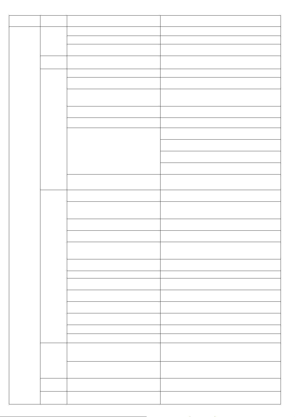
4.2 TROUBLESHOOTING
NOTE: FOLLOWING BEHAVIORS ARE NORMAL CHARACTERISTIC OF OPERATION AND NOT TROUBLES
• Variable speed of the fan.
• Display of message ESA and ES2 in case of operation without load or low load.
• A 2 minute delay for dryer to start after pressing the on/off switch.
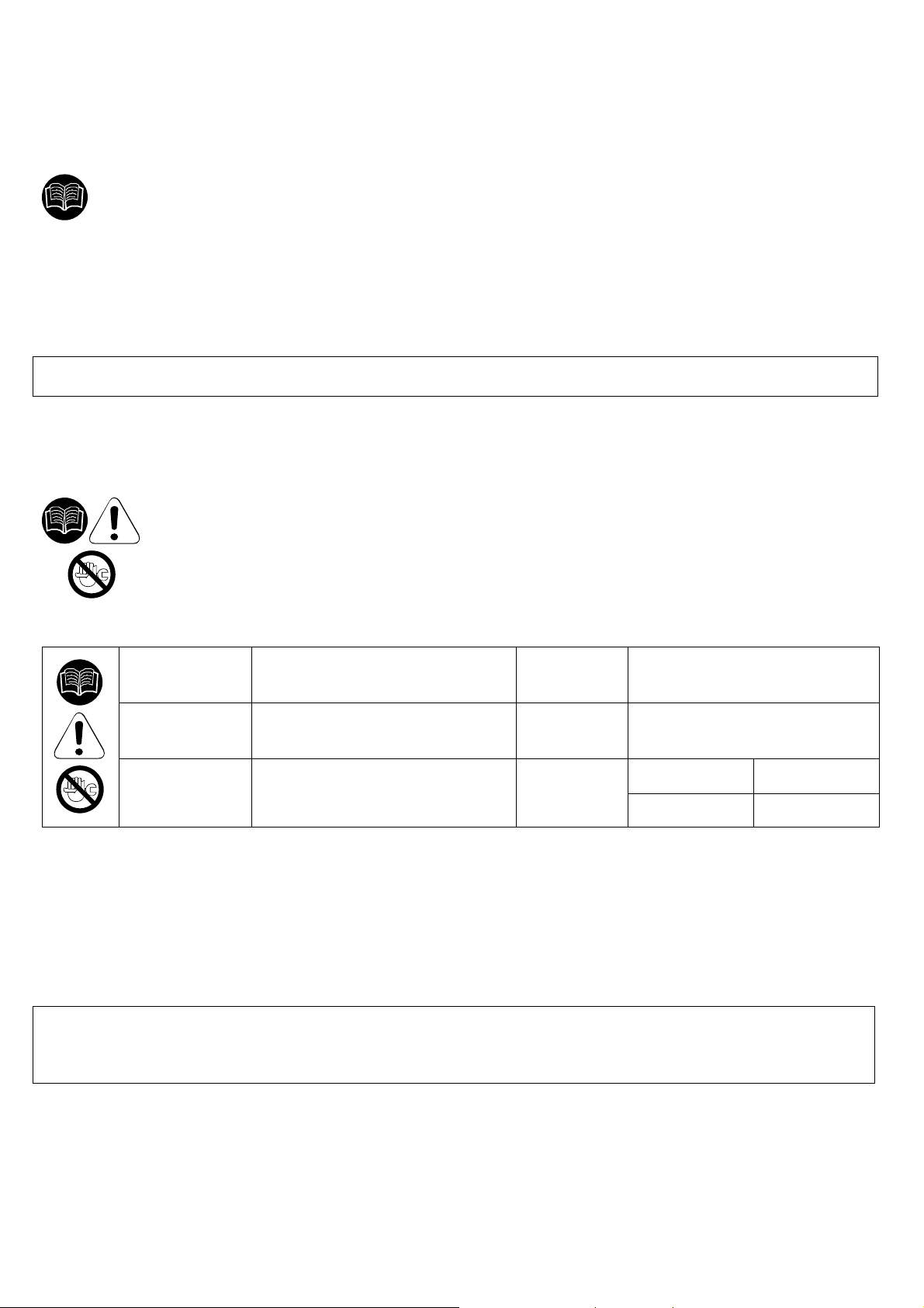
Troubleshooting and eventual control and/or maintenance operations must be performed
by qualified personnel.
For maintaining the refrigerating circuit of the machine, contact a refrigeration engineer.
Cod. 710.0134.39.00 Rev1B – 01.2009
9 - 29
Page 11
TROUBLE DISPLAY
Control
panel
display is
blank
POSSIBLE CAUSE REMEDY
No power in the line. Restore the power in the line.
Problems with cabling. Check cabling; if the trouble persists, replace it.
Problems with the electronic control
board.
The dryer is off.
Dryer in stand-by. Wait 2 minutes after the dryer is switched on.
Compressed air inlet/outlet inverted.
The flow rate and/or temperature of the
air entering the dryer are higher than the
nominal values.
The ambient temperature is higher than
the nominal values.
The condenser is dirty. Clean the condenser.
Condensate drain is not functioning.
The temperature control probe is
positioned improperly or faulty.
Problems with cabling or with the
electronic control board.
Activation of compressor’s internal
thermal protection.
Problems with the electrical components
of the compressor.
Check the electronic control board; if the trouble
persists, replace it.
Turn it on by pressing the ON/OFF switch for 1
second.
Check if the compressed air inlet/outlet is connected
properly.
Restore the nominal conditions.
Restore the nominal conditions.
Clean the condensate drainage system pre-filter.
(Pic.3)
Replace the coil of the drainage solenoid valve if
burned.
Clean or replace the drainage solenoid valve if
clogged/jammed.
Check the C8 and C9 parameters of the electronic
control board; if the trouble persists, replace it.
Check the probe; if the trouble persists, replace it.
Check the cabling and the electronic control board, if
the trouble persists, replace them.
Wait one hour and check again. If the fault persists:
stop dryer and call your local Ingersoll Rand
distributor.
Check the electrical components of the compressor.
WATER IN THE SYSTEM
Cod. 710.0134.39.00 Rev1B – 01.2009
Defective compressor. Replace the compressor.
The flow rate and/or temperature of the
air entering the dryer are higher than the
Restore the nominal conditions.
nominal values.
the nominal values.
The condenser is dirty. Clean the condenser.
The temperature control probe is
positioned improperly or faulty.
Fan pressure switch defective or burned
out (if present).
High pressure switch defective or burned
out (if present).
Gas leakage in the refrigerating circuit.
The ambient temperature is higher than
Restore the nominal conditions.
Check the probe; if the trouble persists, replace it.
Turn off the dryer and call your local Ingersoll Rand
distributor.
Turn off the dryer and call your local Ingersoll Rand
distributor.
Turn off the dryer and call your local Ingersoll Rand
distributor.
Defective fan. Replace the fan.
Protection fuse burned out (if present). Replace the fuse.
The temperature control probe is
positioned improperly or faulty.
Gas leakage in the refrigerating circuit
without load.
The temperature control probe is
positioned improperly or faulty.
Series of alarms very close to each
other.
10 - 29
Check the probe; if the trouble persists, replace it.
Turn off the dryer and call your local Ingersoll Rand
distributor.
Check the probe; if the trouble persists, replace it.
Call your local Ingersoll Rand distributor.
Page 12
in compliance with the
TROUBLE DISPLAY
LOW PRESSURE IN THE LINE
Ice formation in the evaporator.
Clog.
Air flows continuously through the
condensate drainage.
POSSIBLE CAUSE REMEDY
Check the probe; if the trouble persists, replace it.
Check the electronic control board; if the trouble
persists, replace it.
Contact our Service Centre to check the gas charge.
Check if the compressed air inlet/outlet is connected
properly.
Check if the connecting tubing is clogged; in case
proceed accordingly.
Check if any valves are closed.
Check the condition of any filter.
Drainage solenoid valve jammed, clean or replace it.
Verify the condensate drainage times set on the
electronic control board (C8 and C9).
Check the signal from the control board: if it is
continuous, replace the control board.
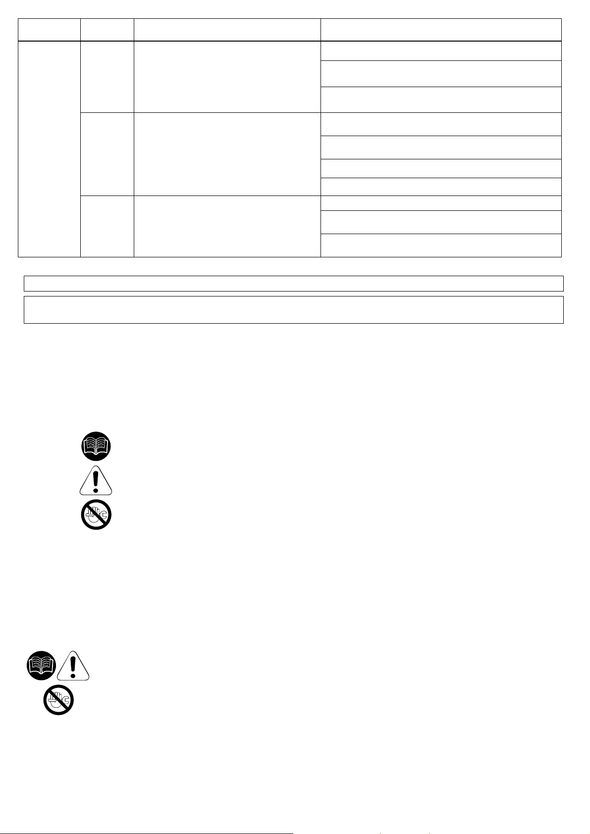
IMPORTANT:
The temperature control probe is extremely delicate. Do not remove the probe from its position. In case
of any kind of problem, please contact your local Ingersoll Rand distributor
Pic.3
4.3 DECOMMISSIONING
In case of necessity, decommission the machine and the relevant packaging
rules locally in force.
Pay particular attention to the refrigerant, as it contains part of the refrigerating compressor lubricating
oil.
Always contact a waste disposal and recycling facility.
Cod. 710.0134.39.00 Rev1B – 01.2009
11 - 29
Page 13
1A1
1B1
1M1
1M2
1P1
1P2
1Q1
1Q2
1S1
1S2
1T1
1V1
CB
CBL
CND
CNV
CPL
EB
ED
EH
EP
EQ
EVA
F1 – F2
FD
FF
FH
FP
FQ
FR
FV
G
IM
K1
K2
PCP
PR
PSC
RBF
RR
RT1
SC
SCO
SLI
SSC
TEMP
TH
TLT
VB
VE
VNR
VT
X1-X2
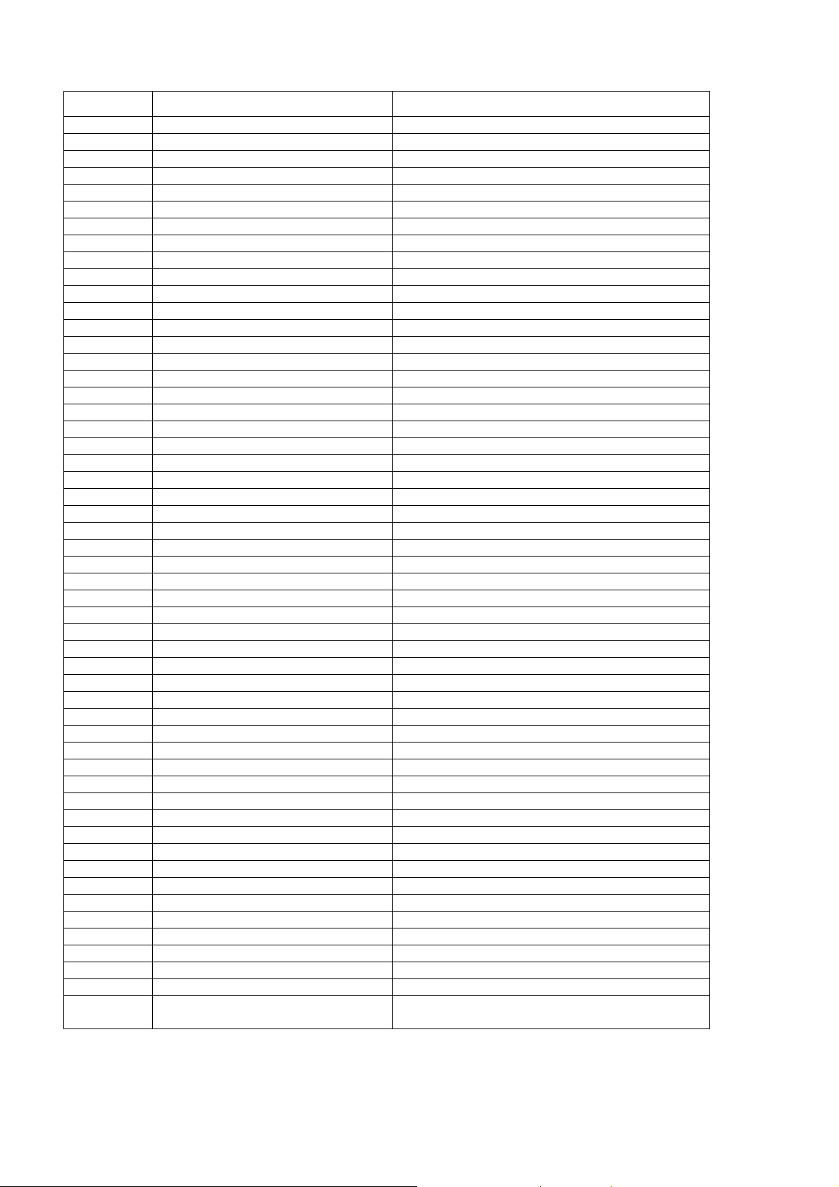
ATTACHMENTS TO THIS MANUAL - ANNEXES AU MANUEL
Legend - Légende:
Pos. - GB - DESCRIPTION - F - DESCRIPTION
Electronic Controller Contrôleur électronique
Drain solenoid valve coil Bobine électrovalve de décharge
Refrigerant compressor Compresseur réfrigérant
Fan Motor Ventilateur
High pressure Switch Pressostat haute pression
Fan pressure Switch Pressostat de ventilation
Compressor circuit breaker Interrupteur automatique de compresseur
Fan circuit breaker Interrupteur automatique de ventilation
Main power switch Interrupteur général
Plug Fiche
Transformer Transformateur
Solenoid drain Valve Purge de condensants
Compressor box Boîte de compresseur
Cables câbles
Condenser Condenseur
Fan capacitor Condenseur de ventilation
Capillary tube Tubo capillaire
Electrical box Boîte électrique
10 micron filter element Cartouche 10 micron
0.01 micron filter element Cartouche 0.01 micron
1 micron filter element Cartouche 1 micron
5 micron filter element Cartouche 5 micron
Evaporator Evaporateur
Fuses Fusibles
Air filter 10 micron Filtre à air 10 micron
Filter dryer Filtre déshydrateur
Air filter 0.01 micron Filtre à air 0.01 micron
Air filter 1 micron Filtre à air 1 micron
Air filter 5 micron Filtre à air 5 micron
Drain screen Filtro a red
Fan motor fuse Fusible de ventilateur
Grid Grille
Moisture indicator Indicateur d'humidité
Contactor switch Commutat. de conjoncteur
Fan contactor switch Commutat. de conjoncteur de ventilateur
Thermal protection Protection thermique
Air-air heat exchanger Echangeur air-air
Air-air heat exchanger (D__IT) Echangeur air-air (D__IT)
Tap with strainer Valve à bille avec le tamis
Rotalock cock Robinet rotalock
Temperature probes Sondes de température
Heat exchanger base Base de l’échangeur de chaleur
Condensate separator Séparateur de condensants
Liquid separator Liquide séparateur
Condensate drain Purge de condensants
Time setter Temporisateur
Thermostat Thermostat
Remote cont. Thermostat Tele Thermostat digital
By-pass hot gas valve Vanne de fréon
Expansion valve Soupape d’ expansion
One way valves with strainer Soupape unidirection. / filtre
Fan blade Ventilateur
X3-XM
Cod. 710.0134.39.00 Rev1B – 01.2009
Terminal blocks Boîte terminale électrique
21 - 29
Page 14
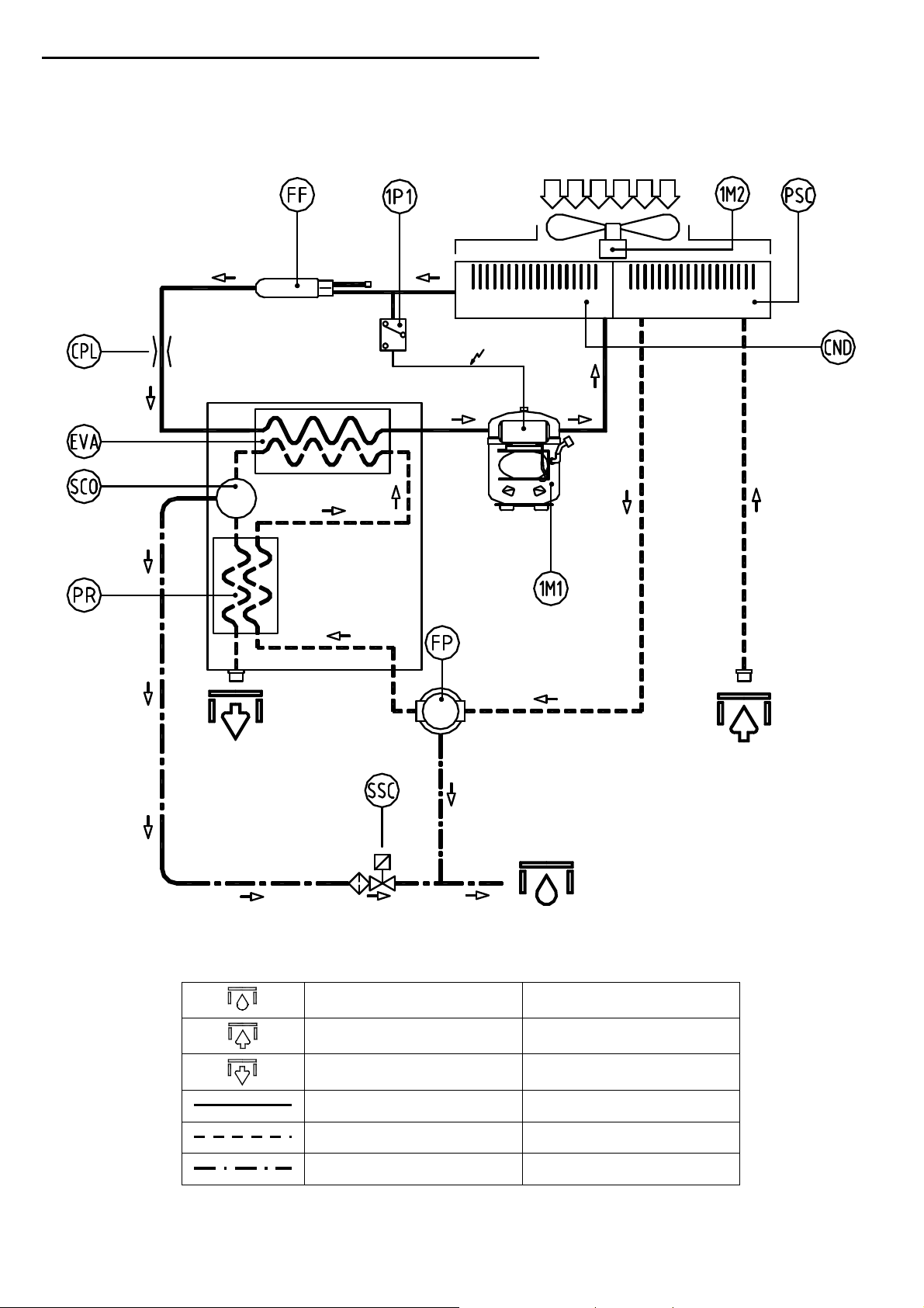
A) REFRIGERANT CIRCUIT - CIRCUIT FRIGORIFÉRIQUE
Cod. 713.0005.07.00 – Rev. 00
Models D25IT to D170IT
Cod. 710.0134.39.00 Rev1B – 01.2009
22 - 29
Condensate drain Purge de condensant
Air inlet Entrée de l'air
Air outlet Sortie de l'air
Refrigerant line Ligne réfrigérant
Compressed air line Ligne de l'air comprimé
Condensate drain line Ligne de drainage
Page 15
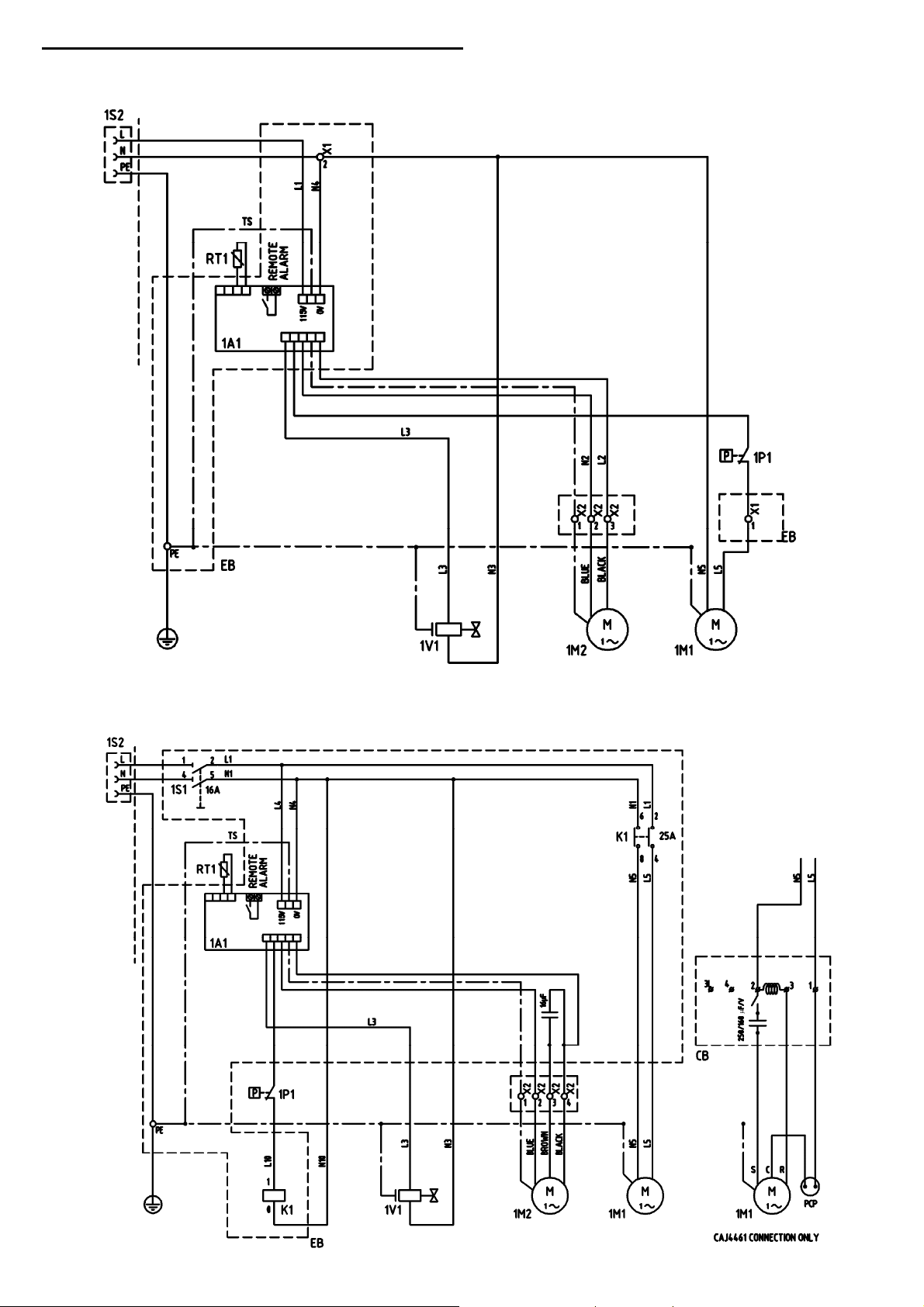
B) WIRING DIAGRAM - SCHEMA ÉLECTRIQUE
Cod. 714.0164.02.00 – Rev. 00
Models D25IT to D60IT (115V/1Ph/60Hz)
Cod. 714.0165.02.00 – Rev. 00
Models D102IT to D170IT (115V/1Ph/60Hz)
Cod. 710.0134.39.00 Rev1B – 01.2009
23 - 29
Page 16
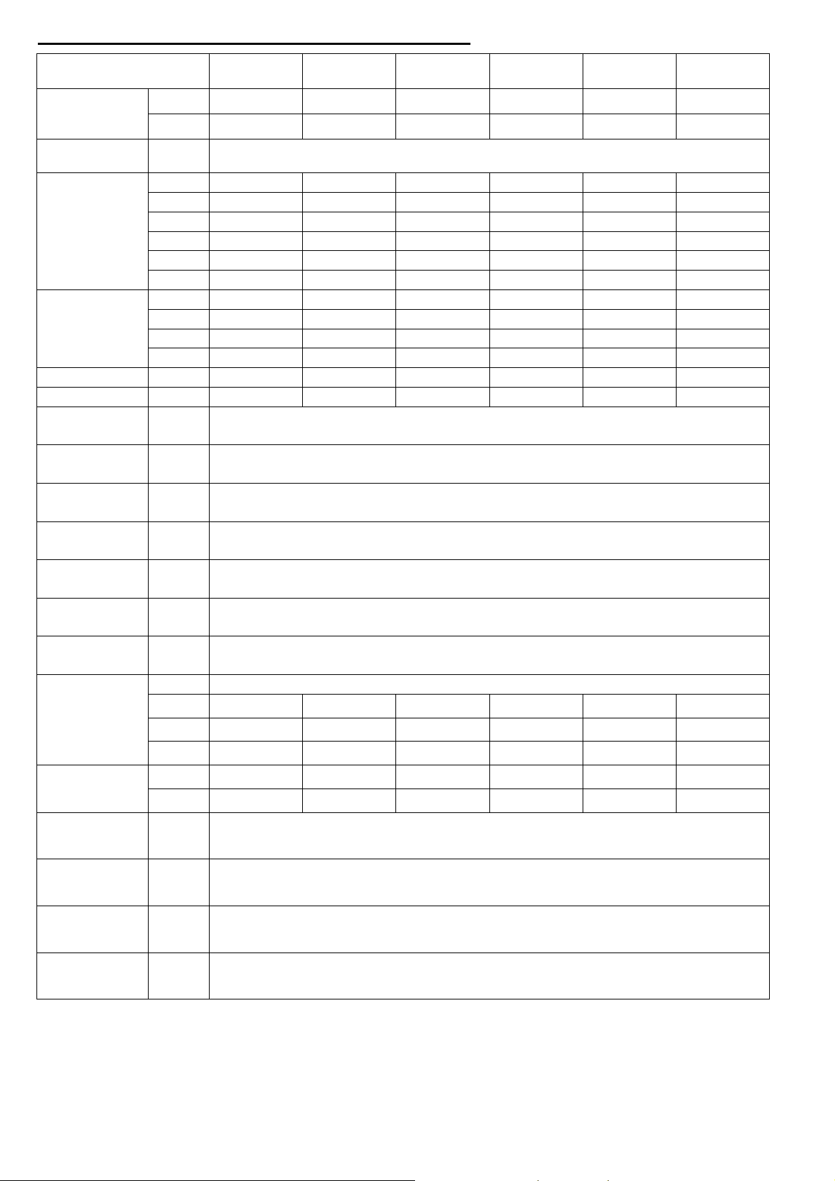
+ / - 5%
C) DATA SHEET - CARACTERISTIQUES TECHNIQUES
MODEL D25IT D42IT D60IT D102IT D140IT D170IT
AR
cfm
15 25 35 60 82 100
AIR FLOW
RATE*
POW SUPPLY
M3/h
VOLT/
PH/HZ
25 42 60 102 140 170
115/1/60
HP 1/6 1/4 1/4 1/2 1/2 2/3
kW 0,21 0,37 0,37 0,48 0,57 0,71
1M1
COMPRESSOR
Max kW
RLA 2,51 4,23 4,23 5,63 6,56 8,16
0,27 0,49 0,49 0,66 0,75 1,14
FLA 2,95 5,24 5,24 6,96 7,97 11,6
LRA 23 35 35 34 37 47
QTY 1 1 1 1 1 1
1M2
FAN
HP 1/20 1/20 1/20 1/5 1/5 1/5
RLA 1.60 1.60 1.60 1.73 1.73 1.73
LRA 2.10 2.10 2.10 2.02 2.02 2.02
TOTAL A A 5 7 7 11 11 13.5
CONNECTION NPT ½" ½" ½" 3/4" 3/4" 1"
AIR T
AIR T MAX
AMB T
AMB T MIN-MAX
AIR W PRESS
AIR PRESS MAX
DEW POINT*
°F 150
°C 66
°F 200
°C 94
°F 95
°C 35
°F 36 – 122
°C 2 – 50
psi 100
bar 7
psi 203
bar 14
°F < 50 (ISO CLASS 6)
°C < 10 (ISO CLASS 6)
TYPE R134a
REF.
REFRIGERANT
LB 0.51 0.88 0.88 0.88 1.06 1.17
OZ 8.10 14.1 14.1 14.1 16.9 18.7
KG 0.23 0.40 0.40 0.40 0.48 0.53
W
WEIGHT
LB 83.8 86.0 86.0 125.7 136.7 147.7
KG 38 39 39 57 62 67
°F 37 – 43
EVAP. TEMP.*
°C 3 – 6
SUCTION
TEMP.*
°F 39 – 46
°C 4 – 8
psig 170 – 230
DISCH. PRESS.*
Bar 12 – 16
HP SWITCH
SETTING
*Rating conditions of: 66°C (150°F) and 100 psig Air Inlet, 35°C (95°F) Ambient
*Conditions de fonctionnement de: 66°C (150°F) et 100 psig air en entrée, 35°C (95°F) température amb ient
psig 435
Bar 30
Performance and specifications - Performances et caractéristiques techniques
Cod. 710.0134.39.00 Rev1B – 01.2009
24 - 29
Page 17
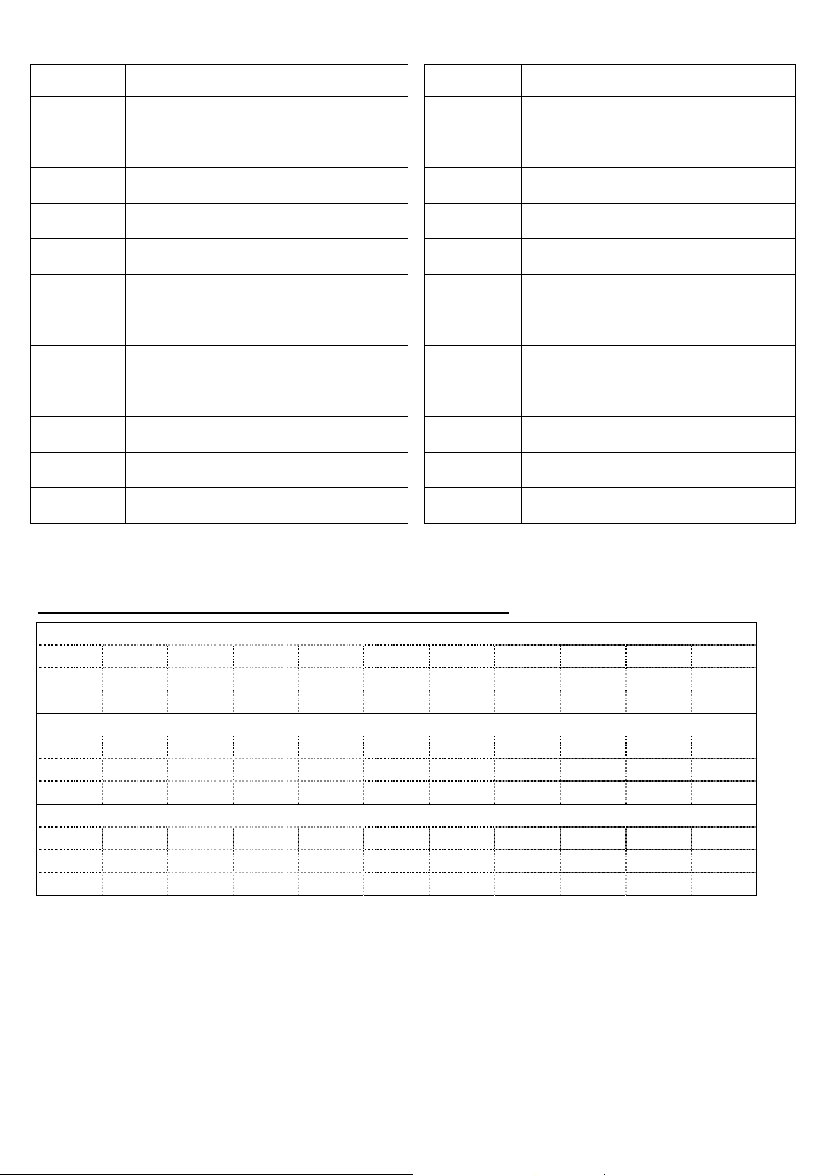
Legend - Légende:
Pos. - GB - DESCRIPTION - F - DESCRIPTION Pos. - GB - DESCRIPTION - F - DESCRIPTION
AR
POW SUPPLY
HP
kW
Max kW
RLA
FLA
LRA
TOTAL A
CONNECTION
AIR T
AIR T MAX
Air flow rate Performances
Power supply Alimentation
Nominal power Puissance nom.
Nominal consumption Consommation nom.
Full load consumption Cons. pleine charge
Nominal Current Ampère nominale
Full load current Ampère pl. charge
Locked rotor current Ampère max.
Total current Ampère total
Air connections Connexion aircomp.
Air inlet temperature Temp. entrée d’air
Max. air inlet temperature
Temp. entrée d’air
max.
AMB T
AMB T MIN-
MAX
AIR W PRESS
AIR PRESS
MAX
DEWP
REF
W
EVAP. TEMP
SUCTION TEMP
DISCH. PRESS.
HP SWITCH
SETTING
D) CORRECTION FACTORS - FACTEURS DE CORRECTION
Ambient temperature Temp. ambiante
Min-Max. ambient
temperature
Air working pressure Pression travail d’air
Max. air pressure Pression max. d’air
Pressure dew point Pression pt de rosée
Refrigerant Réfrigérant
Weight Poids
Evaporation
Temperature
Suction Temperature
Discharge Pressure Pression de décharge
High pressure switch
setting
Temp. Ambiante min-
max.
Température
d'évaporation
Température
d'aspiration
Réglage du pressostat
de haute pression
Correction factor for working pressure - Facteur de correction pour la pression du travail
bar
5 6 7 8 9 10 11 12 13 14
psi 73 87 102 116 131 145 160 174 188,5 203
FC1
Correction factor for inlet air temperature - Facteur de correction pour la température de l'air d'entrée
°C
°F 120 140 150 160 170 180 200
FC3
Correction factor for ambient temperature- Facteur de correction pour la température ambiante
°C
°F 80 90 95 105 110 120
FC2
Calculation of the dryer REAL FLOW RATE = nominal dryer flow rate x FC1 x FC2 x FC3
Calcul du DÉBIT RÉEL du séchoir = débit nominal du séchoir x FC1 x FC2 x FC3
Calculation of the GIVEN FLOW RATE to select a suitable dryer = given flow rate ÷ FC1 ÷ FC2 ÷ FC3
Calcul du DÉBIT DONNÉ pour sélectionner un séchoir approprié = débit donné ÷ FC1 ÷ FC2 ÷ FC3
0,85 0,93 1 1,06 1,11 1,15 1,18 1,2 1,22 1,24
49 60 66 71 76,5 82 93,3
1,25 1,1 1 0,93 0,83 0,75 0,5
26,5 32 35 40,5 43,5 49
1,22 1,07 1 0,75 0,6 0,28
Cod. 710.0134.39.00 Rev1B – 01.2009
25 - 29
Page 18
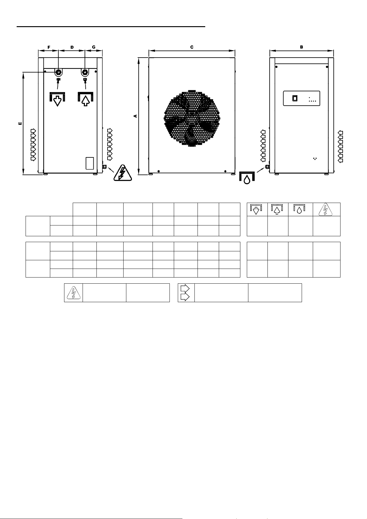
E) DRYER DIMENSIONS - DIMENSIONS DU SECHEUR
D25IT
to
D60IT
D102IT
to
D140IT
D170IT
mm 651 386 500 175 597 105 105
inches 25" 5/8 15" 3/16 19" 11/16 6" 7/8 23" 1/2 4" 1/8 4" 1/8
mm 771 420 567 175 676 133 115
inches 30" 3/8 16" 9/16 22" 5/16 6" 7/8 26" 5/8 5" 1/4 4" 1/2
mm 771 420 567 175 676 133 115
inches 30" 3/8 16" 9/16 22" 5/16 6" 7/8 26" 5/8 5" 1/4 4" 1/2
A B C D E F G
Power supply Alimentation
Air flow Circulation de l'air
1/2"
NPT
3/4"
NPT
1"
NPT
1/2"
NPT
3/4"
NPT
1"
NPT
Ø 6mm
Ø 6mm
Ø 6mm
115/1/60
V/ph/Hz
115/1/60
V/ph/Hz
115/1/60
V/ph/Hz
Cod. 710.0134.39.00 Rev1B – 01.2009
26 - 29
Page 19
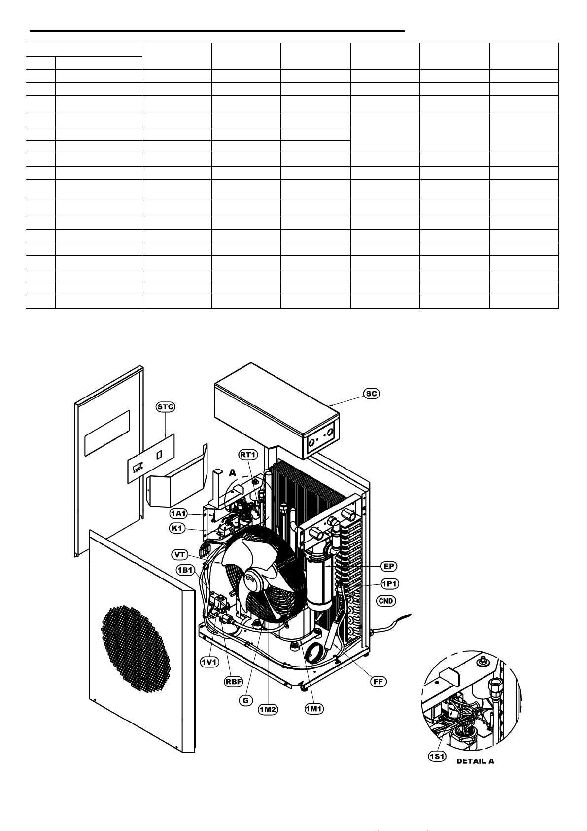
F) BASIC SPARE PARTS - PIÈCES DE RECHANGE ESSENTIELLES
Model
Pos.
1A1
RT1
1M1
1M2
1P1
1S1
1V1
1B1
CND
RBF
STC
Electronic Controller 38457404 38457404 38457404 38457404 38457404 38457404
Temperature probe 38457412 38457412 38457412 38457412 38457412 38457412
VT
G
High pressure Switch 38457511 38457511 38457511 38457511 38457511 38457511
Main power switch - - - 38457826 38457826 38457826
Complete solenoid
Drain solenoid valve
FF
EP
1 micron filter element
Tap with strainer 38457636 38457636 38457636 38457636 38457636 38457636
K1
SC
Contactor switch - - - 38457644 38457644 38457644
Heat exchanger base 38457651 38457651 38457651 38457669 38457677 38457677
Control panel cover 38457685 38457685 38457685 38457685 38457685 38457685
Element
Refrigerant
compressor
Fan Motor 38457479 38457479 38457479
Fan blade 38457495 38457495 38457495
Grid 38457503 38457503 38457503
drain valve
coil
Condenser 38457552 38457552 38457560 38457578 38457586 38457586
Filter dryer 38457594 38457594 38457594 38457602 38457602 38457602
D25IT D42IT D60IT D102IT D140IT D170IT
38457420 38457438 38457438 38457446 38457453 38457461
34857487 34857487 34857487
38457537 38457537 38457537 38457537 38457537 38457537
38457545 38457545 38457545 38457545 38457545 38457545
38457610 38457610 38457610 38457628 38457628 38457628
Cod. 710.0134.39.00 Rev1B – 01.2009
27 - 29
 Loading...