

Page 1
Operating & Maintenance Manual
Compressor Models
CSA XHP1070WCAT
Code: B
This manual contains important safety information.
Do not destroy this manual. This manual must be available to the personnel who
operate and maintain this machine.
Utility Equipment
P.O. Box 868 - 501 Sanford Ave
Mocksville, N.C. 27028
Book: 23012958 (2-16-07) Rev. A
Page 2

Page 3

TABLE OF CONTENTS
Operating & Maintenance Manual
TITLE PAGE
FOREWORD. . . . . . . . . . . . . . . . . . . . . . . . . . . . . . . . . . . . . . . . . . . . . . . . . . . . . . . . . . . . . . 7
SAFETY . . . . . . . . . . . . . . . . . . . . . . . . . . . . . . . . . . . . . . . . . . . . . . . . . . . . . . . . . . . . . . . . 11
Safety Precautions . . . . . . . . . . . . . . . . . . . . . . . . . . . . . . . . . . . . . . . . . . . . . . . . . . . . . . . . . . . . . . . . . 12
General Information . . . . . . . . . . . . . . . . . . . . . . . . . . . . . . . . . . . . . . . . . . . . . . . . . . . . . . . . . . . . .12
Compressed Air . . . . . . . . . . . . . . . . . . . . . . . . . . . . . . . . . . . . . . . . . . . . . . . . . . . . . . . . . . . . . . . .13
Materials. . . . . . . . . . . . . . . . . . . . . . . . . . . . . . . . . . . . . . . . . . . . . . . . . . . . . . . . . . . . . . . . . . . . . . 14
Battery . . . . . . . . . . . . . . . . . . . . . . . . . . . . . . . . . . . . . . . . . . . . . . . . . . . . . . . . . . . . . . . . . . . . . . .15
Radiator . . . . . . . . . . . . . . . . . . . . . . . . . . . . . . . . . . . . . . . . . . . . . . . . . . . . . . . . . . . . . . . . . . . . . .15
Transport . . . . . . . . . . . . . . . . . . . . . . . . . . . . . . . . . . . . . . . . . . . . . . . . . . . . . . . . . . . . . . . . . . . . .16
Decals. . . . . . . . . . . . . . . . . . . . . . . . . . . . . . . . . . . . . . . . . . . . . . . . . . . . . . . . . . . . . . . . . . . . . . . . 17
GENERAL DATA . . . . . . . . . . . . . . . . . . . . . . . . . . . . . . . . . . . . . . . . . . . . . . . . . . . . . . . . . 19
OPERATING INSTRUCTIONS. . . . . . . . . . . . . . . . . . . . . . . . . . . . . . . . . . . . . . . . . . . . . . . 23
Operating Controls and Instruments. . . . . . . . . . . . . . . . . . . . . . . . . . . . . . . . . . . . . . . . . . . . . . . . . . . .24
Lifting Unit. . . . . . . . . . . . . . . . . . . . . . . . . . . . . . . . . . . . . . . . . . . . . . . . . . . . . . . . . . . . . . . . . . . . .25
Before Towing . . . . . . . . . . . . . . . . . . . . . . . . . . . . . . . . . . . . . . . . . . . . . . . . . . . . . . . . . . . . . . . . .26
Towing . . . . . . . . . . . . . . . . . . . . . . . . . . . . . . . . . . . . . . . . . . . . . . . . . . . . . . . . . . . . . . . . . . . . . . . 26
Setting Up (All Units) . . . . . . . . . . . . . . . . . . . . . . . . . . . . . . . . . . . . . . . . . . . . . . . . . . . . . . . . . . . .26
Before Starting . . . . . . . . . . . . . . . . . . . . . . . . . . . . . . . . . . . . . . . . . . . . . . . . . . . . . . . . . . . . . . . . . 27
Starting . . . . . . . . . . . . . . . . . . . . . . . . . . . . . . . . . . . . . . . . . . . . . . . . . . . . . . . . . . . . . . . . . . . . . . . 29
Normal Operation. . . . . . . . . . . . . . . . . . . . . . . . . . . . . . . . . . . . . . . . . . . . . . . . . . . . . . . . . . . . . . . 30
Stopping . . . . . . . . . . . . . . . . . . . . . . . . . . . . . . . . . . . . . . . . . . . . . . . . . . . . . . . . . . . . . . . . . . . . . .31
Pressure Regulation . . . . . . . . . . . . . . . . . . . . . . . . . . . . . . . . . . . . . . . . . . . . . . . . . . . . . . . . . . . . . . . .32
Before Starting Unit - . . . . . . . . . . . . . . . . . . . . . . . . . . . . . . . . . . . . . . . . . . . . . . . . . . . . . . . . . . . .32
TROUBLE SHOOTING. . . . . . . . . . . . . . . . . . . . . . . . . . . . . . . . . . . . . . . . . . . . . . . . . . . . . 35
Introduction . . . . . . . . . . . . . . . . . . . . . . . . . . . . . . . . . . . . . . . . . . . . . . . . . . . . . . . . . . . . . . . . . . . . . . .36
Trouble Shooting Chart. . . . . . . . . . . . . . . . . . . . . . . . . . . . . . . . . . . . . . . . . . . . . . . . . . . . . . . . . . . . . . 37
MAINTENANCE . . . . . . . . . . . . . . . . . . . . . . . . . . . . . . . . . . . . . . . . . . . . . . . . . . . . . . . . . . 41
Routine Maintenance . . . . . . . . . . . . . . . . . . . . . . . . . . . . . . . . . . . . . . . . . . . . . . . . . . . . . . . . . . . . . . .44
Prior to attempting any maintenance work, ensure that:-. . . . . . . . . . . . . . . . . . . . . . . . . . . . . . . . .45
Prior to opening or removing panels or covers to work inside a machine, ensure that:- . . . . . . . . . 45
Prior to attempting any maintenance work on a running machine, ensure that:- . . . . . . . . . . . . . . .45
Protective Shutdown System . . . . . . . . . . . . . . . . . . . . . . . . . . . . . . . . . . . . . . . . . . . . . . . . . . . . . . . . .46
Low engine fuel level switch. . . . . . . . . . . . . . . . . . . . . . . . . . . . . . . . . . . . . . . . . . . . . . . . . . . . . . .46
Scavenge Line . . . . . . . . . . . . . . . . . . . . . . . . . . . . . . . . . . . . . . . . . . . . . . . . . . . . . . . . . . . . . . . . . . . .46
Compressor Oil Filter . . . . . . . . . . . . . . . . . . . . . . . . . . . . . . . . . . . . . . . . . . . . . . . . . . . . . . . . . . . . . . . 47
Removal . . . . . . . . . . . . . . . . . . . . . . . . . . . . . . . . . . . . . . . . . . . . . . . . . . . . . . . . . . . . . . . . . . . . . .47
lnspection . . . . . . . . . . . . . . . . . . . . . . . . . . . . . . . . . . . . . . . . . . . . . . . . . . . . . . . . . . . . . . . . . . . . . 47
3
Page 4

TABLE OF CONTENTS
Operating & Maintenance Manual
TITLE PAGE
Reassembly . . . . . . . . . . . . . . . . . . . . . . . . . . . . . . . . . . . . . . . . . . . . . . . . . . . . . . . . . . . . . . . . . . . 48
Compressor Oil Separator Element . . . . . . . . . . . . . . . . . . . . . . . . . . . . . . . . . . . . . . . . . . . . . . . . . . . .48
Removal . . . . . . . . . . . . . . . . . . . . . . . . . . . . . . . . . . . . . . . . . . . . . . . . . . . . . . . . . . . . . . . . . . . . . .48
lnspection . . . . . . . . . . . . . . . . . . . . . . . . . . . . . . . . . . . . . . . . . . . . . . . . . . . . . . . . . . . . . . . . . . . . . 48
Reassembly . . . . . . . . . . . . . . . . . . . . . . . . . . . . . . . . . . . . . . . . . . . . . . . . . . . . . . . . . . . . . . . . . . . 49
Compressor Oil Cooler and Engine Radiator . . . . . . . . . . . . . . . . . . . . . . . . . . . . . . . . . . . . . . . . . . . . .49
Air Filter Elements. . . . . . . . . . . . . . . . . . . . . . . . . . . . . . . . . . . . . . . . . . . . . . . . . . . . . . . . . . . . . . . . . .50
Removal . . . . . . . . . . . . . . . . . . . . . . . . . . . . . . . . . . . . . . . . . . . . . . . . . . . . . . . . . . . . . . . . . . . . . .50
Reassembly . . . . . . . . . . . . . . . . . . . . . . . . . . . . . . . . . . . . . . . . . . . . . . . . . . . . . . . . . . . . . . . . . . . 50
Ventilation . . . . . . . . . . . . . . . . . . . . . . . . . . . . . . . . . . . . . . . . . . . . . . . . . . . . . . . . . . . . . . . . . . . . . . . .50
Cooling Fan Drive . . . . . . . . . . . . . . . . . . . . . . . . . . . . . . . . . . . . . . . . . . . . . . . . . . . . . . . . . . . . . . . . . . 50
Fuel System . . . . . . . . . . . . . . . . . . . . . . . . . . . . . . . . . . . . . . . . . . . . . . . . . . . . . . . . . . . . . . . . . . . . . . 51
Fuel Filter Water Separator. . . . . . . . . . . . . . . . . . . . . . . . . . . . . . . . . . . . . . . . . . . . . . . . . . . . . . . . . . .51
Hoses . . . . . . . . . . . . . . . . . . . . . . . . . . . . . . . . . . . . . . . . . . . . . . . . . . . . . . . . . . . . . . . . . . . . . . . . . . .51
Electrical System. . . . . . . . . . . . . . . . . . . . . . . . . . . . . . . . . . . . . . . . . . . . . . . . . . . . . . . . . . . . . . . . . . .51
Battery. . . . . . . . . . . . . . . . . . . . . . . . . . . . . . . . . . . . . . . . . . . . . . . . . . . . . . . . . . . . . . . . . . . . . . . . . . . 51
Pressure System. . . . . . . . . . . . . . . . . . . . . . . . . . . . . . . . . . . . . . . . . . . . . . . . . . . . . . . . . . . . . . . . . . . 52
Tire Pressure. . . . . . . . . . . . . . . . . . . . . . . . . . . . . . . . . . . . . . . . . . . . . . . . . . . . . . . . . . . . . . . . . . . . . .52
Running Gear/wheels . . . . . . . . . . . . . . . . . . . . . . . . . . . . . . . . . . . . . . . . . . . . . . . . . . . . . . . . . . . . . . .52
Lubrication. . . . . . . . . . . . . . . . . . . . . . . . . . . . . . . . . . . . . . . . . . . . . . . . . . . . . . . . . . . . . . . . . . . . . . . .52
Engine Lubricating Oil. . . . . . . . . . . . . . . . . . . . . . . . . . . . . . . . . . . . . . . . . . . . . . . . . . . . . . . . . . . . . . .52
Compressor Lubricating Oil. . . . . . . . . . . . . . . . . . . . . . . . . . . . . . . . . . . . . . . . . . . . . . . . . . . . . . . . . . .53
Running Gear Wheel Bearings . . . . . . . . . . . . . . . . . . . . . . . . . . . . . . . . . . . . . . . . . . . . . . . . . . . . . . . . 53
LUBRICATION . . . . . . . . . . . . . . . . . . . . . . . . . . . . . . . . . . . . . . . . . . . . . . . . . . . . . . . . . . . 55
General Information . . . . . . . . . . . . . . . . . . . . . . . . . . . . . . . . . . . . . . . . . . . . . . . . . . . . . . . . . . . . . . . .56
Compressor Oil Change . . . . . . . . . . . . . . . . . . . . . . . . . . . . . . . . . . . . . . . . . . . . . . . . . . . . . . . . . . . . .56
Portable Compressor Fluid Chart . . . . . . . . . . . . . . . . . . . . . . . . . . . . . . . . . . . . . . . . . . . . . . . . . . . . . . 58
4
Page 5

TABLE OF CONTENTS
Operating & Maintenance Manual
TITLE PAGE
5
Page 6

**Always use Ingersoll-Rand Replacement parts!**
6
Page 7

Foreword
Book: 23012958 (2-16-07) Rev. A 7
Page 8

Operating & Maintenance Manual Foreword
Foreword
Nothing contained in this document is intended to extend any promise, warranty or
representation, expressed or implied, regarding the Ingersoll-Rand products described herein.
Any such warranties or other terms and conditions of sale of products shall be in accordance
with the standard terms and conditions of sale for such products, which are available upon
request.
This manual contains instructions and technical data to cover all routine operation and
scheduled maintenance tasks by operation and maintenance staff. Major overhauls are
outside the scope of this manual and should be referred to an authorized Ingersoll-Rand
service department.
All components, accessories, pipes and connectors added to the compressed air system
should be:
• of good quality, procured from a reputable manufacturer and, wherever possible, be
of a type approved by Ingersoll-Rand.
• clearly rated for a pressure at least equal to the machine maximum allowable working
pressure.
• compatible with the compressor lubricant/coolant.
• accompanied with instructions for safe installation, operation and maintenance.
Details of approved equipment are available from Ingersoll-Rand Service departments. The
use of repair parts other than those included within the Ingersoll-Rand approved parts list may
create hazardous conditions over which Ingersoll-Rand has no control. Therefore, IngersollRand cannot be held responsible for equipment in which non-approved repair parts are
installed.
Ingersoll-Rand reserves the right to make changes and improvements to products without
notice and without incurring any obligation to make such changes or add such improvements
to products sold previously.
The intended uses of this machine are outlined below and examples of unapproved usage are
also given. However, Ingersoll-Rand cannot anticipate every application or work situation that
may arise. If in doubt, consult supervision.
This machine has been designed and supplied for above ground operation to be used for
compression of normal ambient air containing no additional gases, vapors or particles within
the ambient temperature range specified in the general data section of this manual.
This machine should not be used:
A. For direct or indirect human consumption of the compressed air.
B. Outside the ambient temperature range specified in the general data section of
this manual.
C. When an actual or forese eable risk of hazardou s levels of fla mmable gases or
vapors exists.
D. With other than Ingersoll-Rand approved components.
E. With guards, or controls or switches missing or disabled.
8 Book: 23012958 (2-16-07) Rev. A
Page 9

Foreword Operating & Maintenance Manual
F. For storage or transportation of materials inside or on the enclosure.
This company accepts no responsibility for errors in translation of this manual from the original
English version.
You as the customer are expected to provide certain service and maintenance items. Your
Ingersoll-Rand dealer will provide all other more detailed service and maintenance items on a
special preventive maintenance schedule for each machine. It is very important that the
minimum service and maintenance requirements explained in this manual be performed at the
required intervals. Exceeding these intervals may reduce the reliability of the machine.
The purpose of this manual is to train the operator with functions, operation, and basic service
and maintenance requirements of the compressor. During the preparation of this manual,
every effort was made to ensure the adequacy and accuracy of the contents.
Your Ingersoll-Rand dealer will assist with setup and initial startup of the compressor. He will
also provide brief operating and service instructions and will insure that a copy of this manual
is included with the machine. Before starting the compressor, this manual and instructions
should be carefully read to obtain a thorough knowledge of the duties to be performed. Please
take pride in the compressor, keep it clean, and in good mechanical condition.
To enable proper maintenance records, Ingersoll-Rand provides a Noise Emission Control
Maintenance Log Book (PCD Form 685) with each compressor shipped from the factory. This
Log Book contains a recommended schedule and space so that the serviceman can note what
service and maintenance was done, by whom, where, and when.
Book: 23012958 (2-16-07) Rev. A 9
Page 10

**Always use Ingersoll-Rand Replacement parts!**
10 Book: 23012958 (2-16-07) Rev. A
Page 11

Safety
Book: 23012958 (2-16-07) Rev. A 11
Page 12

Operating & Maintenance Manual Safety
Safety
Safety Precautions
General Information
Never operate unit without first observing all safety warnings and carefully reading the
operation and maintenance manual shipped from the factory with this machine.
Ensure that the operator reads and understands the decals and consults the manuals before
maintenance or operation.
Ensure that maintenance personnel are adequately trained, competent and have read the
Maintenancce Manuals.
Make sure that all protective covers are in place and that the canopy/do ors are closed during
operation.
The specification of this machine is such that the machine is not suitable fo r use in flammable
gas risk areas. If such an application is required then all local regulations, codes of practice
and site rules must be observed. To ensure that the machine can operate in a safe and reliable
manner, additional equipment such as gas detection, exhaust spark arrestors, and intake
(shut-off) valves may be required, dependent on local regulations or the degree of risk
involved.
A weekly visual check must be made on all fasteners/fixing screws securing mechanical parts.
In particular, safety-related parts such as coupling hitch, drawbar components, road-wheels,
and lifting bail should be checked for total security.
All components which are loose, damaged or unserviceable, must be rectified without delay.
Air discharged from this machine may contain carbon monoxide or other contaminants which
will cause serious injury or death. Do not breathe this air.
This machine produces loud noise with the doors open or service valve vented. Extended
exposure to loud noise can cause hearing loss. Always wear hearing protection when doors
are open or service valve is vented.
Never inspect or service unit without first disconnecting battery cable(s) to prevent accidental
starting.
Do not use petroleum products (solvents or fuels) under high pressure as this can penetrate
the skin and result in serious illness. Wear eye protection while cleaning unit with compressed
air to prevent debris from injuring eye(s).
Rotating fan blade can cause serious injury. Do not operate without guard in place.
Use care to avoid contacting hot surfaces (engine exhaust manifold and piping, air receiver
and air discharge piping, etc.).
Ether is an extremely volatile, highly inflammable gas. When it is specified as a starting aid,
use sparingly. DO NOT USE ETHER IF THE MACHINE HAS GLOW PLUGS OR INLET
HEATER STARTING AIDS OR ENGINE DAMAGE WILL RESULT.
12 Book: 23012958 (2-16-07) Rev. A
Page 13

Safety Operating & Maintenance Manual
Never operate unit with guards, covers or screens removed. Keep hands, hair, clothing, tools,
blow gun tips, etc. well away from moving parts.
Compressed Air
Compressed air can be dangerous if incorrectly handled. Before doing any work on the unit,
ensure that all pressure is vented from the system and that the machine cannot be started
accidentally.
Ensure that the machine is operating at the rated pressure and that the rated pressure is
known to all relevant personnel.
All air pressure equipment installed in or connected to the machine must have safe working
pressure ratings of at least the machine safety valve setting.
If more than one compressor is connected to one common downstream plant, effective check
valves and isolation valves must be fitted and controlled by work procedures, so that one
machine cannot accidentally be pressurized or over pressurized by another.
Compressed air must not be used for a direct feed to any form of breathing appar atus or mask.
High Pressure Air can cause serious injury or death. Relieve pressure before removing filler
plugs/caps, fittings or covers.
Air pressure can remain trapped in air supply line which can result in serious injury or death.
Always carefully vent air supply line at tool or vent valve before performing any service.
The discharged air contains a very small percentage of compressor lubricating oil and care
should be taken to ensure that downstream equipment is compatible.
If the discharged air is to be ultimately released into a confined space, adequate ventilation
must be provided.
When using compressed air, always use appropriate personal protective equipment.
All pressure containing parts, especially flexible hoses and their couplings, must be regularly
inspected, be free from defects and be replaced according to the Manual instructions.
Avoid bodily contact with compressed air.
The safety valve located in the separator tank must be checked periodically for correct
operation.
Whenever the machine is stopped, air will flow back into the compressor system f rom devices
or systems downstream of the machine unless the service valve is closed. Install a check valve
at the machine service valve to prevent reverse flow in the vent of an unexpected shutdown
when the service valve is open.
Disconnected air hoses whip and can cause serious injury or death. Always attach a safety
flow restrictor to each hose at the source of supply or branch line in accordance with OSHA
Regulation 29CFR Section 1926.302(b).
Never allow the unit to sit stopped with pressure in the receiver-separator system.
Book: 23012958 (2-16-07) Rev. A 13
Page 14

Operating & Maintenance Manual Safety
Materials
The following substances may be produced during the operation of this machine:
• brake lining dust
• engine exhaust fumes
!
WARNING
Avoid inhalation
Ensure that adequate ventilation of the cooling system and exhaust gases is maintained at all
times.
The following substances are used in the manufacture of this machine and may be hazardous
to health if used incorrectly:
•anti-freeze
• compressor lubricant
• engine lubricant
• preservative grease
• rust preventative
• diesel fuel
• battery electrolyte
!
WARNING
Avoid ingestion, skin contact and inhalation of fumes
Should compressor lubricant come into contact with the eyes, then irrigate with water for at
least 5 minutes.
Should compressor lubricant come into contact with the skin, then wash off immediately.
Consult a physician if large amounts of compressor lubricant are ingested.
Consult a physician if compressor lubricant is inhaled.
Never give fluids or induce vomiting if the patient is unconscious or having convulsions.
Safety data sheets for compressor and engine lubricants should be obtained from the lubricant
supplier.
Do NOT start or operate this machine in a confined area. Avoid breathing exhaust fumes when
working on or near the machine.
14 Book: 23012958 (2-16-07) Rev. A
Page 15

Safety Operating & Maintenance Manual
This machine may include such materials as oil, diesel fuel, antifreeze, brake fluid, oil/air filters
and batteries which may require proper disposal when performing maintenance and service
tasks. Contact local authorities for proper disposal of these materials.
Battery
A battery contains sulfuric acid and can give off gases which are corrosive and potentially
explosive. Avoid contact with skin, eyes and clothing. In case of contact, flush area
immediately with water.
!
WARNING
Do not attempt to slave start a frozen battery since this may cause it to
explode.
Exercise extreme caution when using booster battery. To jump battery, connect ends of one
booster cable to the positive (+) terminal of each battery. Connect one end of other cable to
the negative (-) terminal of the booster battery and other end to a ground connection away
from dead battery (to avoid a spark occurring near any explosive gases that may be present).
After starting unit, always disconnect cables in reverse order.
Radiator
Hot engine coolant and steam can cause injury. Ensure that the radiator filler cap is removed
with due care and attention.
Do not remove the pressure cap from a HOT radiator. Allow radiator to cool down before
removing pressure cap.
Book: 23012958 (2-16-07) Rev. A 15
Page 16

Operating & Maintenance Manual Safety
Transport
When loading or transporting machines ensure that the specified lifting and tie down points are
used.
When loading or transporting machines ensure that the towing vehicle, its size, weight, towing
hitch and electrical supply are all suitable to provide safe and stable towing at speeds either,
up to the legal maximum for the country in which it is being towed or, as specified for the
machine model if lower than the legal maximum.
Do not exceed gross vehicle weight rating.
Before towing the machine, ensure that:-
• the tires and towing hitch are in a serviceable condition.
• the canopy is secure.
• all ancillary equipment is stored in a safe and secure manner.
• the brakes and lights are functioning correctly and meet necessary road traffic
requirements.
• break-away cables/safety chains are connected to the towing vehicle.
The machine must be towed in a level attitude in order to maintain correct handling, braking
and lighting functions. This can be achieved by correct selection and adjustment of the vehicle
towing hitch and, on variable height running gear, adjustment of the drawbar.
1. Make sure wheels, tires and tow bar connectors are in safe operating condition
and tow bar is properly connected before towing.
2. When parking always use the handbrake and, if necessary, suitable wheel
chocks.
16 Book: 23012958 (2-16-07) Rev. A
Page 17

Safety Operating & Maintenance Manual
Decals
Decals are located on the machine to point out potential safety hazards. Read and
follow these instructions. If you do not understand the instructions, inform your
supervisor.
Note that there are different decal headings:
!
DANGER
(Red Background)
Indicates the presence of a hazard which WILL cause serious injury,
death or property damage, if ignored.
!
WARNING
(Orange Background)
Indicates the presence of a hazard which CAN cause serious injury, death
or property damage, if ignored.
!
CAUTION
(Yellow Background)
Indicates the presence of a hazard which WILL or can cause injury or
property damage, if ignored.
NOTICE
(Blue Background)
Indicates important set-up, operating or maintenance information.
Book: 23012958 (2-16-07) Rev. A 17
Page 18

Operating & Maintenance Manual Safety
FREE SAFETY DECALS
To promote communication of Safety Warnings on
products manufactured by the Portable Compressor
Division in Mocksville, N.C. Safety Decals are available
free of charge. Safety decals are identified by the decal
heading: DANGER, WARNING or CAUTION. Decal part
numbers are on the bottom of each decal and are also
listed in the compressor’s parts manual. Submit orders
for Safety Decals to the Mocksville Parts Service
Department. The no charge order should contain only
Safety Decals. Help promote product safety! Replace
decals that are not readable.
18 Book: 23012958 (2-16-07) Rev. A
Page 19

General Data
Book: 23012958 (2-16-07) Rev. A 19
Page 20
Operating & Maintenance Manual General Data
General Data
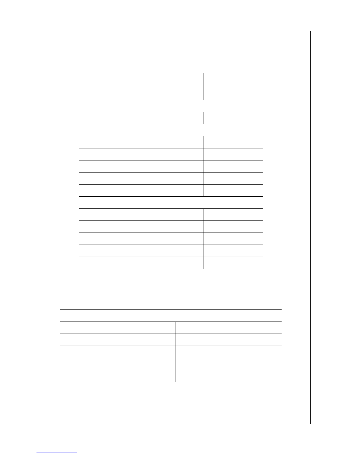
MODELS
Air Delivery - cfm (litres/sec) 1070 (505)
COMPRESSOR
Rated Operating Pressure - psi (kPa) 350 (2400)
ENGINE (Diesel)
Manufacturer Caterpillar
Model 3406TA
Full Load Speed - rpm 1800
No Load Speed - rpm 1350
Electrical System 24VDC
FLUID CAPACITIES - U.S. Gallons (litres)
Compressor Lubricant (initial dry fill) 55 (208)
Compressor Lubricant (service refill) 44 (167)
Engine Crankcase Lubricant 9.0 (34.1)
XHP1070BWCAT
Engine Coolant (radiator) 16.5 (62.5)
Fuel Tank (Clean DIESEL fuel) 180 (680)
Note: Above 15°F (-9°C) use No.2 Diesel Fuel with sulfur
content not greater than 0.5% and minimum cetane number of
42.
UNITS MEASUREMENTS/WEIGHTS
Feet (Meters) Low Speed
Overall Length (drawbar up) 17.0 (5.18)
Overall Height 8.46 (2.58)
Overall Width 7.38 (2.25)
Gross Weight (all fluids) pounds (kg) 15,200 (6,900)
20 Book: 23012958 (2-16-07) Rev. A
Page 21
General Data Operating & Maintenance Manual
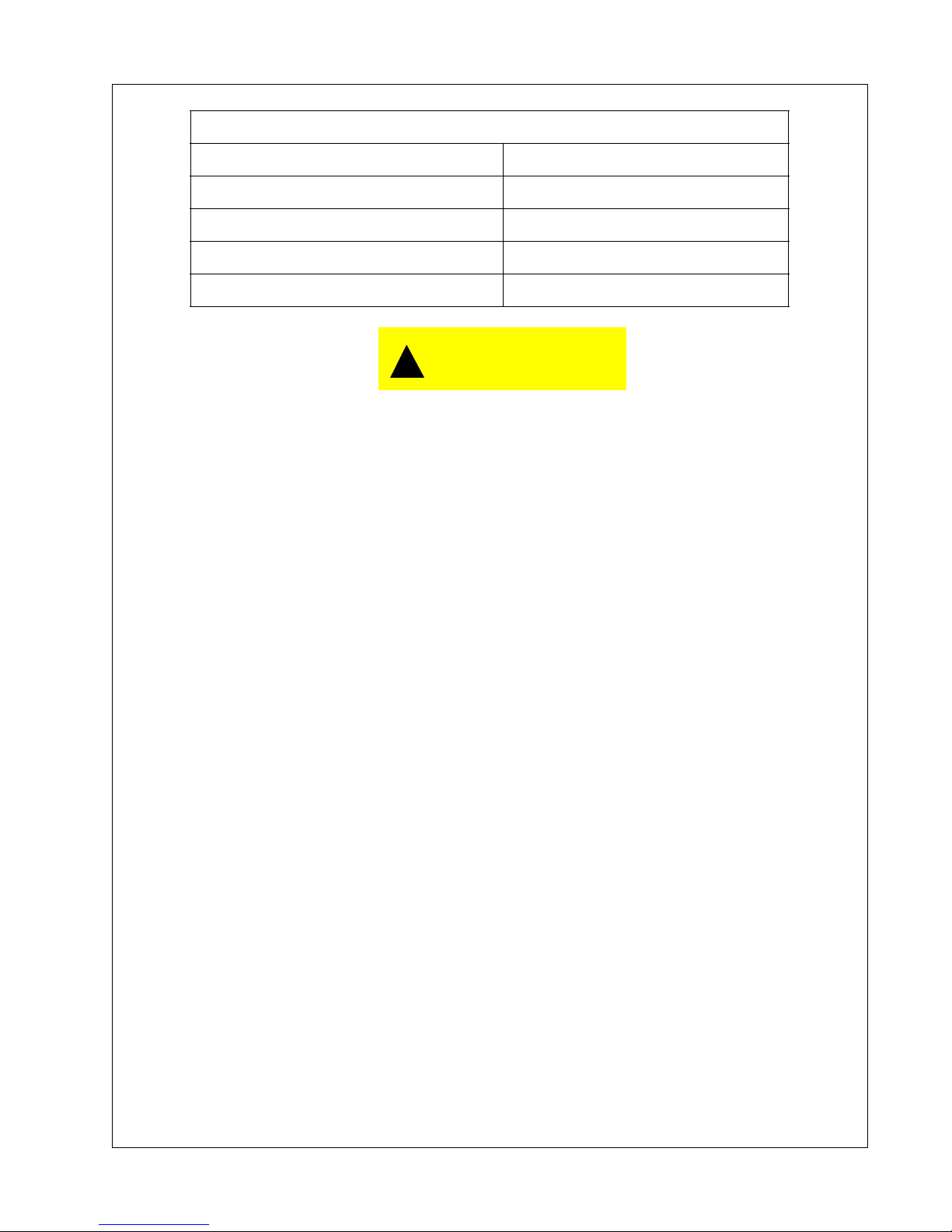
RUNNING GEAR
Low Speed
Tire Size/Load Range 8.25 x 15TR
Load Range “F”
Inflation Pressure (cold) psi (kPa) 105 (720)
Towing Speed (Maximum) mph (km/hr) 20 (32)
!
CAUTION
Any departure from the specifications may make this equipment unsafe.
Book: 23012958 (2-16-07) Rev. A 21
Page 22

**Always use Ingersoll-Rand Replacement parts!**
22
Page 23

Operating Instructions
Book: 23012958 (2-16-07) Rev. A 23
Page 24
Operating & Maintenance Manual Operating Instructions
Operating Instructions
Operating Controls and Instruments
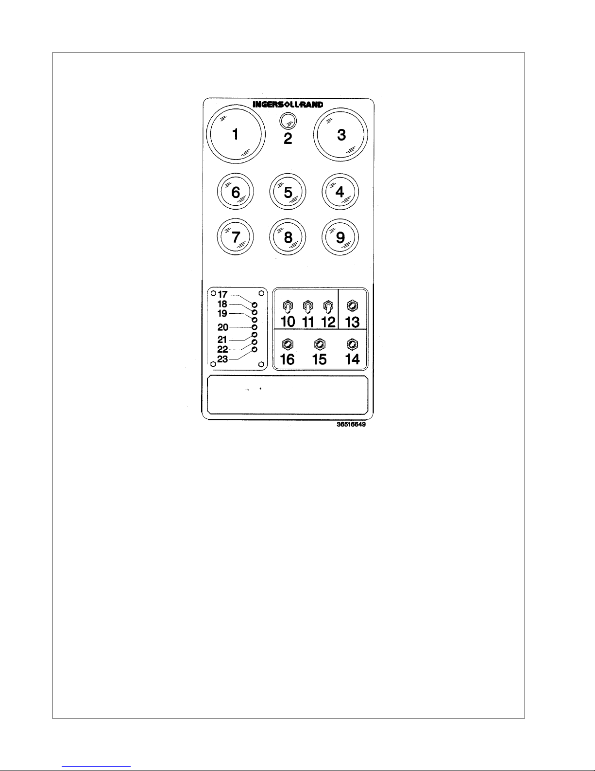
The operating controls and instruments are arranged on the control panel as shown above. A
description of each panel device is as follows:
1. Compressor Disch. Pressure Gauge: Indicates pressure in receiver tank,
normally from 0 psi (kPa) to the rated pressure of the machine.
2. Lamp: Controlled by Switch 11.
3. Engine Tachometer: Indicates engine speed in RPM from 0 when stopped to
full speed.
4. Discharge Air Temperature Gauge: Indicates in °F and °C. Normal operating
range: 185°F/85°C to 230°F/110/°C.
5. Fuel Level Gauge: Indicates about of fuel in tanks.
6. Engine Oil Pressure Gauge: Normal range is 45 to 70 psi (310-480 kPa) at
1800 rpm with SAE 30 oil.
24 Book: 23012958 (2-16-07) Rev. A
Page 25

Operating Instructions Operating & Maintenance Manual
7. Hourmeter: Records running time for maintenance purposes.
8. Voltmeter: Indicates battery condition.
9. Engine Water Temperature Gauge: Indicates coolant temperature with
normal operating range from 180°F (82°C) to 210°F (99°C).
10. Power Switch: Flip “ON” to operate, “OFF” to stop.
11. Lights Switch: Operates Lamp 2 and those within gauges.
12. Heaters Switch: Activates control system heaters for operation below 32°F
(0°C).
13. Service Air Button: After warm-up, provides full air pressure at the service
outlet.
14. Bypass Button: Bypasses automatic shutdown circuit.
15. Start Button: Activates the engine starter.
16. Ether Inject Button: Injects a measured shot.
!
CAUTION
Use Sparingly.
17. High Compressor Temperature: 248°F (120°C).
18. Low Engine Oil Pressure: 12 psi (80kPa) or less.
19. High Engine Temperature: Coolant above 220°F (104°C)
20. Low Fuel Level: Comes on first as a warning and eventually triggers a
shutdown.
21. Alternator Not Charging: Needs attention.
22. Low Coolant Level: Dangerously Low. Needs attention.
23. Air Filters Restricted: Needs servicing.
Lifting Unit
!
WARNING
Do not climb on top of unit. The lifting eye can be reached through the
roof door ONLY from INSIDE of the unit.
The central lifting bail can be reached through the roof door only
Use hoist or crane capable of lifting machine gross weight (see General Data).
Book: 23012958 (2-16-07) Rev. A 25
from inside the machine.
Page 26
Operating & Maintenance Manual Operating Instructions
Before Towing
Ensure that the tires, wheels and running gear are in good condition and secure.
Towing
Do not tow this unit in excess of 20 mph (32km/hr). Use a tow vehicle whose towing capacity
is greater than the gross weight of this unit.
Setting Up (All Units)
Place the unit in an open, well-ventilated area. Position as level as possible. The design of
these units permits a maximum 15 degree sidewise limit on out-of-level operation.
When the unit is to be operated out-of-level, it is important: (1) to keep the engine crankcase
oil level near the high level mark (with the unit level), and (2) to have the compressor oil level
gauge show no more than mid-scale (with the unit running at full load). Do not overfill either
the engine crankcase or the compressor lubricating oil system.
Chock wheels.
!
WARNING
Do not connect the air discharge on this unit onto a comm on header with
any other unit of any description, or any other source of compre ssed air,
without first making sure a check-valve is used between the header and
the unit. If this unit is connected in parallel with another unit of higher
discharge pressure and capacity, a safety hazard could occur in a backflow condition.
!
WARNING
Unrestricted air flow from a hose will result in a whipping motion of the
hose which can cause serious injury or death. A safety device must be
attached to the hose at the source of supply to reduce pressure in case
of hose failure or other sudden pressure release. Reference: OSHA
regulation 29 CFR Section 1926.302 (b).
26 Book: 23012958 (2-16-07) Rev. A
Page 27

Operating Instructions Operating & Maintenance Manual
Air hose restraining cable installation:
Secure hose restraining cable at each end to prevent accidental hose whipping. At the
machine-side of the air hose, install and secure one end of the hose restraining cable on the
3” nipple on the inlet side of the 3” service valve. Install the other end of the hose restraining
cable over the main hose connector.
Install suitable 3” air hose between service valve on unit and point of air use. The air hose must
be rated for outdoor use and for pressurized air service. Minimum rating is 250°F (121°C) a nd
200 psig (HP) or 425 psig (XHP).
Before Starting
Open manual blowdown valve to ensure the separator has been vented of all pressure. Close
the valve before starting.
Inspect the complete installation including remote fuel lines (if any) and air hose routing and
connections.
Check battery for proper connections and condition.
!
WARNING
Combustible gas can cause severe burns, blindness or death. Keep
sparks and open flame away from battery.
• Check the compressor fluid level. Maintain the fluid level between bottom and
midway of the sight glass on the separator tank.
• Check engine oil level. The proper level is labeled on the engine dipstick. Add oil
when required. Do not overfill.
• To jump-start, connect the positive booster/charger cable to the 24VDC positive (+)
terminal of the battery. Then connect the negative booster/charger cable to the
engine block...Not to the negative (-) terminal of the weak battery. After starting,
disconnect the negative (-) cable from engine block; then from the booster battery/
charger. Disconnect positive (+) cable from both batteries.
Book: 23012958 (2-16-07) Rev. A 27
Page 28

Operating & Maintenance Manual Operating Instructions
!
WARNING
Do not remove the cap from a HOT engine radiator. The sudden release
of pressure from a heated cooling system can result in a loss of coolant
and possible severe personal injury.
!
WARNING
Hot pressurized fluid can cause serious burns. Do not open radiator while
hot.
Check coolant to assure coolant level is at minimum level when the unit is cold.
Check engine coolant level on coolant recovery bottle on inside of rear door. Add coolant as
required.
Insure that radiator cap is installed properly and tightened.
NOTE: This machine will not allow engine starting if engine coolant is low.
NOTICE
If the appropriate mixture of antifreeze is not used during freezing
temperatures, failure to drain the engine may cause costly engine
damage. Never use water only, as corrosion inhibitors are required in
engine coolant fluid.
!
CAUTION
No smoking, sparks, or open flame near fuel.
Check the fuel level. Add only CLEAN DIESEL fuel for maximum service from the engine.
Refer to the Engine Operator’s Section for fuel specifications.
NOTICE
To minimize condensation (water) in the fuel tank, it is recommended to
fill the tank at the end of each day.
28 Book: 23012958 (2-16-07) Rev. A
Page 29

Operating Instructions Operating & Maintenance Manual
NOTE: This machine will not allow engine starting if the fuel level is below
the minimum fuel shut off level.
!
WARNING
This machine produces loud noise with doors open. Extended exposure
to loud noise can cause hearing loss. Wear hearing protection when
doors or valve(s) are open.
• Close the side doors to maintain a cooling air path and to avoid recirculation of hot
air. This will maximize the life of the engine and compressor and protect the hearing
of surrounding personnel.
• Make sure no one is IN or ON the compressor unit.
Starting
NOTICE
This unit is equipped with a battery disconnect switch which removes
power from the machine controller for long term storage. The switch is
located on the side of the engine near the battery.
This switch must be turned ON to provide power to the control panel for
starting this unit.
Close the air service valve to isolate the compressor from the compressed air tool until the
engine is warmed up.
1. Turn the keyswitch to the “ON” position (first position). All diagnostic lamps and
the LED display will light for two (2) seconds. All lamps should then go off and
ALTERNATOR NOT CHARGING and LOW ENGINE OIL PRESSURE lamps
will flash.
2. In freezing weather (below 32°F/0°C), flip HEATERS switch “ON” and wait sixty
(60 seconds). This applies heat to the control system components for easier
starting. Leave this switch “ON” while operating at these temperatures.
3. When the keyswitch is turned to “START” the engine starter will be engaged.
Do not operate the engine starter motor for more than ten (10) seconds
without allowing at least one minute cooling time between start attempts.
Extended engine starter engagement will result in starter drop-out and generate a
starter engagement time fault.
Book: 23012958 (2-16-07) Rev. A 29
Page 30

Operating & Maintenance Manual Operating Instructions
!
CAUTION
Ether is an extremely volatile, high flammable gas. Use Sparingly! If too
much is injected, the uncontrolled explosion may result in costly damage
to the engine.
4. In cold weather, as required, press the ETHER INJECT button once or twice
only while the engine is cranking. This injects a measured amount of ETHER
to the engine.
5. Following a successful start, the engine will accelerate to 1200 rpm initially,
then 1500 rpm for warm-up. Compressor discharge pressure will be maintained
at 60 psi during warm-up. After warm-up, rpm will maintain 1200 rpm idle.
6. Press the LOAD button. The engine will increase speed up to 1800 rpm until
the pressure reaches the desired set point.
After the engine has warmed up, open the service air valve to supply air to compressed air tool.
Normal Operation
The Operator may observe and monitor operating parameters using the gages on the panel.
In the event the machine controller detects a parameter outside normal operating limits, the
unit will shutdown.
In the event the machine controller detects a parameter at a dangerously high or low level, the
machine will be automatically stopped with the cause of the SHUTDOWN shown on the
diagnostic lights and display.
Delivered air volume at set point pressure is accomplished by two methods:
1. The compressor is loaded (inlet valve fully open or modulated partially open) or
unloaded (inlet valve fully closed).
2. Engine speed varies between 1350 RPM and 1800 RPM while compressor is
loaded to match the required volume flow.
Operation - Loaded
Assume engine has been started and is running in the unload state at 1350 RPM. If there is
air demand (pressure falls below the load point pressure), compressor will load at 1350 RPM
by opening the inlet valve. As air demand rises and falls, engine speed is controlled between
1200 RPM and 1800 RPM to match the required flow while maintaining rated pressure.
Operation - Unloaded
If there is no air demand at 1350 RPM (pressure rises above the unload point pressure), the
compressor will unload by closing the inlet valve. The unit then runs at 1350 RPM unloaded
with no air delivery. If air demand increases (pressure falls below the load point pressure), the
compressor reloads to meet the required air demand.
30 Book: 23012958 (2-16-07) Rev. A
Page 31

Operating Instructions Operating & Maintenance Manual
Stopping
• Close air service valve(s).
• Allow the unit to run at “IDLE” for 3 to 5 minutes to reduce the engine temperatures.
• Turn the keyswitch to the “OFF” position.
NOTICE
Failure to allow turbo cool down prior to stopping can cause
turbocharger damage.
!
CAUTION
Machines with EMERGENCY STOP BUTTON - Use the Emergency Stop
Button only for emergency conditions. Do not use for normal machine
stopping. Button must be reset before starting can be accomplished.
NOTICE
Once the engine stops, the automatic blowdown valve will relieve
pressure from the separator tank.
!
WARNING
Even after pressure is relieved from the piping system, any air supply line
from the compressor to a tool or machine could remain under pressure
and cause serious personal injury or death. After the compressor stops,
carefully open a valve at any tool or machine to exhaust the pressure in
any line prior to removal or servicing.
!
CAUTION
Never allow the unit to sit stopped with pressure in the receiver-separator
system. As a precaution, open the service valve.
Book: 23012958 (2-16-07) Rev. A 31
Page 32
Operating & Maintenance Manual Operating Instructions
Pressure Regulation
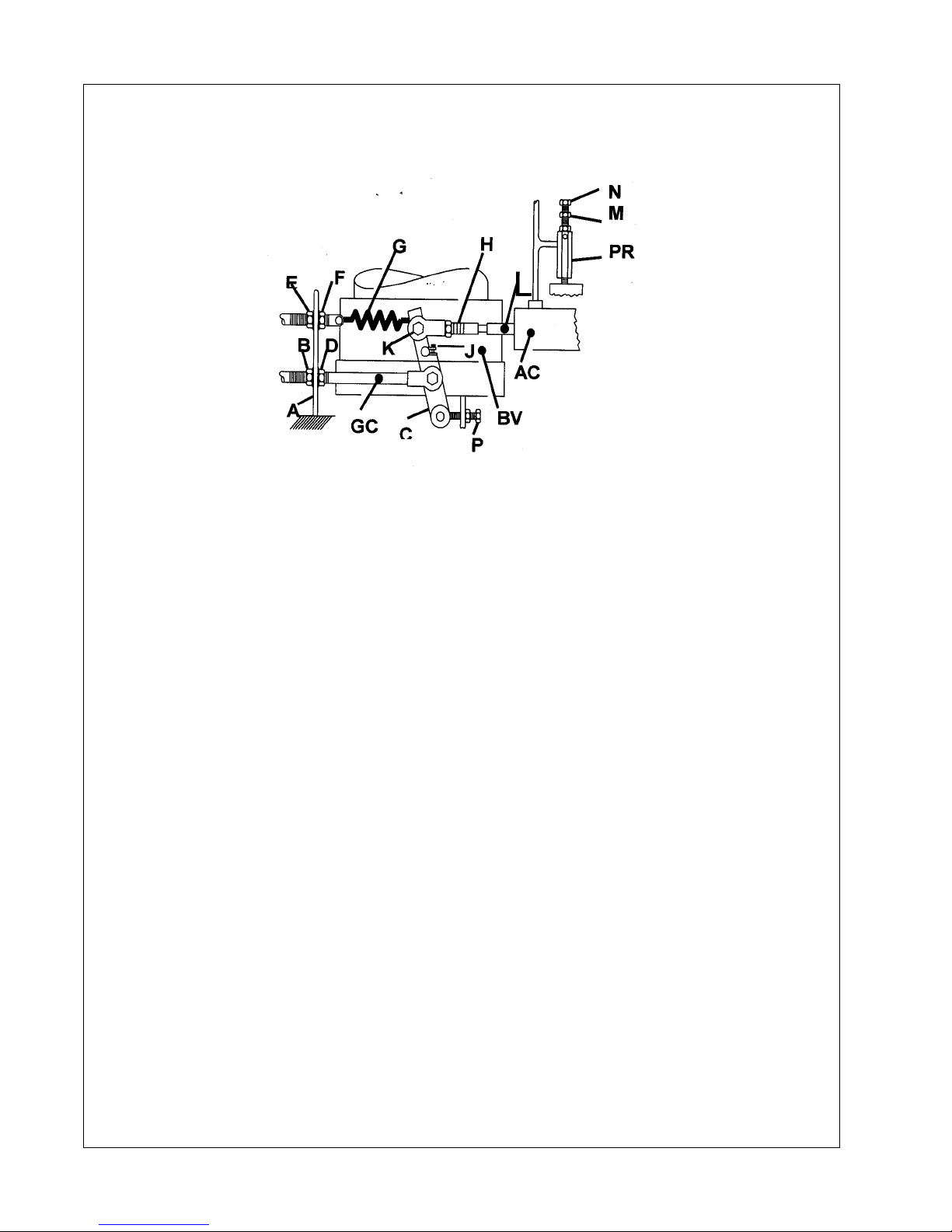
Normally, regulation requires no adjusting; but if proper adjustment is lost, proceed as follo ws:
Before Starting Unit -
1. WITH UNIT STOPPED, disconnect rod end bearing on governor cable (GC) at
engine governor lever.
2. At bracket (A) near butterfly valve (BV) run nut (B) back on governor cable
housing. Push governor cable housing toward lever (C). Tighten nut (D).
3. Loosen screw (J) on lever (C).
4. Loosen nut (E) to relax spring (G).
5. Loosen nut (H). Turn rod (L) in Air Cylinder (AC) until approximately 3/4 inch
(20 mm) between nut (H) and flats on rod (L).
6. With locking pliers, clamp onto butterfly valve shaft and rotate and hold it so
butterfly valve is fully shut. Place a wrench on lever screw (K) and rotate
butterfly valve lever (C) so air cylinder rod (L) fully bottoms out in air cylinder.
While holding the butterfly valve closed AND holding air cylinder shaft fully in,
tighten lever screw (J). Then release hold on butterfly valve shaft and lever.
7. Turn rod (L) One complete turn CW as viewed from rod end. This opens the
butterfly valve slightly. Tighten nut (H). Rotate butterfly shaft/lever (C), open
and closed, several times to assure that linkage is not binding.
8. With engine governor lever in full speed position, reconnect rod end bearing.
9. Move linkage to closed position, and verify that travel is positively stopped by
the rod reaching the bottom of the air cylinder. The butterfly valve should not
seat closed.
32 Book: 23012958 (2-16-07) Rev. A
Page 33

Operating Instructions Operating & Maintenance Manual
10. Take slack out of spring (G) by moving nuts (E) and (F). Tighten nuts.
11. Start unit and allow to warm up for 3 to 5 minutes.
12. The target pressure is 50 to 80 psi while operating at start pressure.
13. If the pressure exceeds 80 psi: Loosen jam nut (H), turn rod (L) 1/4 to 1/2 turn
CCW (as viewed from rod end) to slightly close butterfly, and secure jam nut.
Use the manual blowdown valve to bleed pressure down to 60 psi. After 2.0
minutes, if the pressure is between 50 and 80 psi, OK. Adjustment complete.
14. If the pressure drops below 50 psi: Loosen jam nut (H), turn rod (L) 1/4 to 1/2
turn CW (as viewed from rod end) to slightly open the butterfly, and secure jam
nut. After 2.0 minutes, if the pressure is between 50 and 80 psi, OK. Adjustment
complete.
15. If the pressure is not between 50 and 80 psi after 2.0 minutes, repeat steps 13
and/or 14 as needed.Start unit and allow to warm up for 3 to 5 minutes.
16. Push “Service Air” Button on control panel.
17. With service air valve closed, adjust pressure regulator (PR) to rated pressure
(*) plus 30 psi (70 kPa) as follows:
18. Loosen locknut (M) counterclockwise; Turn adjustment cap (N) clockwise to
increase pressure, counterclockwise to decrease pressure.
19. Set idle speed (*) by adjusting position of rod end bearing on governor cable at
engine. Tighten lock nut.
20. If pressure at unload is unsteady, loosen locknut (H) and rotate rod (L) out of
rod end bearing one quarter turn at a time until steady. Tighten locknut (H).
21. Open service air valve and observe full load engine speed (*). Adjust regulator
to give rated operating pressure (*). Tighten locknut (M).
22. Close and slowly open service air valve. If engine speed surges, increase
tension on spring (G) by moving nuts (E) and (F). If set speeds are n ot correct,
repeat steps14 and15 as required.
23. To regulate to any pressure between 150 psi (1050 kPa) and maximum rating
(*), make adjustments at the pressure regulator.
Book: 23012958 (2-16-07) Rev. A 33
Page 34

**Always use Ingersoll-Rand Replacement parts!**
34 Book: 23012958 (2-16-07) Rev. A
Page 35

Trouble Shooting
Book: 23012958 (2-16-07) Rev. A 35
Page 36

Operating & Maintenance Manual Trouble Shooting
Trouble Shooting
Introduction
Trouble shooting for a portable air compressor is an organized study of a particular
problem or series of problems and a planned method of procedure for investigation and
correction. The trouble shooting chart that follows includes some of the problems that an
operator may encounter during the operation of a portable compressor.
The chart does not attempt to list all of the troubles that may occur, nor does it attempt to
give all of the answers for correction of the problems. The chart does give those problems
that are most apt to occur. To use the trouble shooting chart:
A. Find the “complaint” depicted as a bold heading.
B. Follow down that column to find the potential cause or causes. The causes are
listed in order (1, 2, 3 etc.) to suggest an order to follow in trouble shooting.
A. Think Before Acting
Study the problem thoroughly and ask yourself these questions:
1. What were the warning signals that preceded the trouble?
2. Has a similar trouble occurred before?
3. What previous maintenance work has been done?
4. If the compressor will still operate, is it safe to continue operating it to make
further checks?
B. Do The Simplest Things First
Most troubles are simple and easily corrected. For example, most complaints are “low
capacity” which may be caused by too low an engine speed or “compressor over- heats” which
may be caused by low oil level.
Always check the easiest and most obvious things first; following this simple rule will save time
and trouble.
NOTE: For trouble shooting electrical problems, refer to the Wiring
Diagram Schematic found in Parts List Section.
36 Book: 23012958 (2-16-07) Rev. A
Page 37

Trouble Shooting Operating & Maintenance Manual
Trouble Shooting Chart
Bold Headings depict the COMPLAINT - Subheadings suggest the CAUSE
NOTE: Subheadings suggest sequence to follow troubleshooting.
1. Unit Shutdown: Corrective Action
Out of Fuel Add CLEAN diesel Fuel
Compressor Oil Temp. too High See Complaint 6
Engine Water Temp. too High Check coolant level. If necessary, Add.
Engine Oil Pressure too Low See Complaint 3 and Complaint 4.
Broken Engine Fan Belt Replace fan belt.
Loose Wire Connection
Low Fuel Level Shutdown Replace fuel sender.
Defective Sensor Replace sensor.
Malfunctioning Relay Replace relay.
Blown Fuse Replace fuse.
Engine Malfunctioning See Trouble Shooting in Engine Manual.
Airend Malfunctioning See Complaint 6.
Wiggle wires at switches & connector blocks.
Make repairs.
2. Won’t Start/Run:
Low Battery Voltage Check electrolyte level. Check connections.
Blown Fuse Replace fuse.
Malfunctioning Start Switch Replace switch.
Clogged Fuel Filters Service filters. See Engine Operator’s Manual.
Out of Fuel Add CLEAN fuel.
Compressor Oil Temp. too High See Complaint 6.
Engine Water Temp. too High Check fluid level. If necessary, Add.
Engine Oil Pressure too Low See Complaint 3 and Complaint 4.
Loose Wire Connection Repair or replace connection.
Defective Sensor Replace sensor.
Malfunctioning Relay Replace relay.
Engine Malfunctioning See Trouble Shooting in Engine Manual.
Airend Malfunctioning See Complaint 10, 11.
3. High Engine Temperature
Broken Engine Fan Belt Replace fan belt set.
*Ambient Temp. > 115° F Above spec limit.
Dirty Operating Conditions Move unit to cleaner environment.
Dirty Cooler Clean exterior of cooler.
*Out of Level > 15 degrees Relocate or reposition unit.
Operating Pressure too High Reduce pressure to spec.
Recirculation of Cooling Air Close side doors.
Loose Wire Connection Repair or replace.
* : > = greater than, < = less than
Book: 23012958 (2-16-07) Rev. A 37
Page 38

Operating & Maintenance Manual Trouble Shooting
4. Low Engine Oil Pressure Corrective Action
Low Oil Level Add oil.
Out of Level > 15 degrees Relocate or reposition.
Wrong Lube Oil See Engine Oil Spec. Change oil.
Clogged Oil Filter Element(s) Replace element(s).
Engine Malfunctioning See Trouble Shooting in Engine Manual.
Loose Wire Connection. Repair or replace.
5. Alternator Low Voltage
Loose or Broken Belts Tighten or replace belt set.
Loose Wire Connection Repair or replace connection.
Low Battery Voltage Check electrolyte level. Add if necessary.
Check connectors. Clean & tighten.
Recharge battery.
Malfunctioning Alternator Repair or replace alternator.
6. High Compressor Discharge Temperature:
Ambient Temp. > 115° F Above spec limit.
Out of Level > 15 degrees Relocate or reposition unit.
Low Oil Level Add oil. Look for any leaks.
Wrong Lube Oil Check spec. in this manual.
Dirty Cooler Clean exterior surfaces.
Dirty Operating Conditions Move unit to cleaner environment.
Clogged Oil Filter Elements Replace elements. Change oil.
Loose or Broken Belts Tighten or replace belt set.
Operating Pressure too High Reduce pressure to spec.
Recirculation of Cooling Air Close side doors. Replace belly pan.
Malfunctioning Thermostat Replace thermostat in bypass valve.
Malfunctioning Fan
Defective Oil Cooler Relief Valve Replace valve.
Defective Minimum Pressure Valve Repair or replace valve.
Blocked or Restricted Oil Lines Clean by flushing or replace.
Airend Malfunctioning See Complaint 11, 12
Check fan belt tension. Tighten or replace belt
set.
7. Engine RPM Down:
Clogged Fuel Filter (primary)
Replace primary filter. Replace final filter. Drain
tanks. Add CLEAN fuel.
Operating Pressure too High Reduce pressure to spec limit.
Dirty Air Filter Clean or replace elements.
Wrong Air Filter Element Install correct element.
Engine Malfunctioning See Trouble Shooting in Engine Manual.
Airend Malfunctioning Refer to Factory.
38 Book: 23012958 (2-16-07) Rev. A
Page 39

Trouble Shooting Operating & Maintenance Manual
8. Excessive Vibration:
Rubber Mounts, Loose or Damaged Tighten or replace.
Defective Fan Replace fan.
Drive Coupling Defective Replace coupling.
Engine Malfunctioning See Trouble Shooting in Engine Manual.
Airend Malfunctioning See Complaint 7, 11, 12
Engine idle speed too low. See Engine Manual.
9. Low CFM:
Dirty Air Filter Clean or replace elements.
Incorrect Linkage Adjustment Make adjustment per Section 6.
Malfunctioning Inlet Unloader/Butterfly V alve Inspect valve. Make adjustment per Section 6.
Wrong Air Filter Element Install correct element.
10. Short Air Cleaner Life:
Dirty Operating Conditions Move unit to cleaner environment.
Inadequate Element Cleaning Install new element.
Incorrect Stopping Procedure Read procedure in this manual.
Wrong Air Filter Element Install proper element.
11. Will Not Unload:
Malfunctioning Inlet Butterfly Valve Inspect valve fit. Re-adjust per Section 6.
Ice in Regulation Lines/Orifice Apply heat to line(s) and or orifice.
Load Solenoid Leak Replace load solenoid.
Plugged Vent Leak Clean and/or replace.
12. Safety Valve Relieves:
Operating Pressure too High Reduce pressure to spec limit.
Malfunctioning Inlet Unloader/Butterfly Valve Inspect valve fit. Readjust per Section 6.
Defective Safety Valve Replace safety valve.
Unit will not Unload Fast Enough Apply heat to lines and/or orifice.
Book: 23012958 (2-16-07) Rev. A 39
Page 40

**Always use Ingersoll-Rand Replacement parts!**
40 Book: 23012958 (2-16-07) Rev. A
Page 41

Maintenance
Book: 23012958 (2-16-07) Rev. A 41
Page 42
Operating & Maintenance Manual Maintenance
Maintenance
Initial
500 miles
/850 km
Compressor Oil Level C
Engine Oil Level C
*Radiator Coolant Level C
Gauges/Lamps C
*Air Cleaner Service Indicators C
Fuel Tank (Fill at end of day) C D
*Fuel/Water Separator Drain C
Oil Leaks C
Fuel Leaks C
Drain Water From Fuel Filters D
Coolant Leaks C
Radiator Filler Cap C
Air Cleaner Precleaner Dumps C
Fan/Alternator Belts C
Daily Weekly Monthly
3 Months
500 hrs.
6 Months
1000 hrs.
12
Months
2000 hrs.
Battery Connections/Electrolyte C
Tire Pressure and Surface C
*Wheel Lug Nuts C
Hoses (Oil, Air, Intake, etc.) C
Automatic Shutdown System C
Air Cleaner System C
Compressor Oil Cooler Exterior C
*Engine Rad/Oil Cooler Exterior C
Fasteners, Guards C
Air Cleaner Elements R/WI
*Disregard if not appropriate for this particular machine. D = Drain
(1) or 3000 miles/5000km whichever is the sooner G = Grease
C = Check (adjust, clean or replace as necessary) R = Replace
CBT = Check before towing. T = Test
CR = Check and report W I = or when indicated if earlier.
Refer to specific sections of the operator's manual for
more information.
42 Book: 23012958 (2-16-07) Rev. A
Page 43
Maintenance Operating & Maintenance Manual
Initial
500 miles
/850 km
*Fue/Water Separator Element R
Compressor Oil Filter Element R
Compressor Oil R
Engine Oil Change R
Engine Oil Filter R
*Water Pump Grease. R
*Wheels (Bearings, Seals, etc.) C G
*Engine Coolant CR
Fuel Filter Element R
*Injection Nozzle Check C
Shutdown Switch Settings T
Scavenger Orifice & Related Parts C
Oil Separator Element R
*Feed Pump Strainer Cleaning. C
Daily Weekly Monthly
3 Months
500 hrs.
6 Months
1000 hrs
12
Months
2000 hrs
Months
3000 hrs
18
*Valve Clearance Check C
Lights (running, brake, & turn) CBT
Pintle Eye Bolts CBT
* Brakes C C
* Brake linkage C
* Emergency stop T
Running gear linkage G
Safety valve C
Running gear bolts(1) C
*Disregard if not appropriate for this particular machine. D = Drain
(1) or 3000 miles/5000km whichever is the sooner G = Grease
(2) or as defined by local or national legislation R = Replace
C = Check (adjust, clean or replace as necessary) T = Test
CBT = Check before towing. W I = or when indicated if earlier.
CR = Check and report Refer to specific sections of the operator's manual for
more information.
Book: 23012958 (2-16-07) Rev. A 43
Page 44
Operating & Maintenance Manual Maintenance
Initial
500 miles
/850 km
Scavenge line C
* Engine breather element C
Separator tank (2) exterior CR
*Lubricator (Fill) C
2 Yrs4 Yrs6 Yrs
Safety valve C
Hoses R
Separator tank (2) interior C
*Disregard if not appropriate for this particular machine. D = Drain
(1) or 3000 miles/5000km whichever is the sooner G = Grease
(2) or as defined by local or national legislation R = Replace
C = Check (adjust, clean or replace as necessary) T = Test
Daily Weekly Monthly
3 Months
500 hrs.
6 Months
1000 hrs
12
Months
2000 hrs
CBT = Check before towing. W I = or when indicated if earlier.
CR = Check and report Refer to specific sections of the operator's manual for
more information.
Routine Maintenance
This section refers to the various components which require periodic maintenance and
replacement.
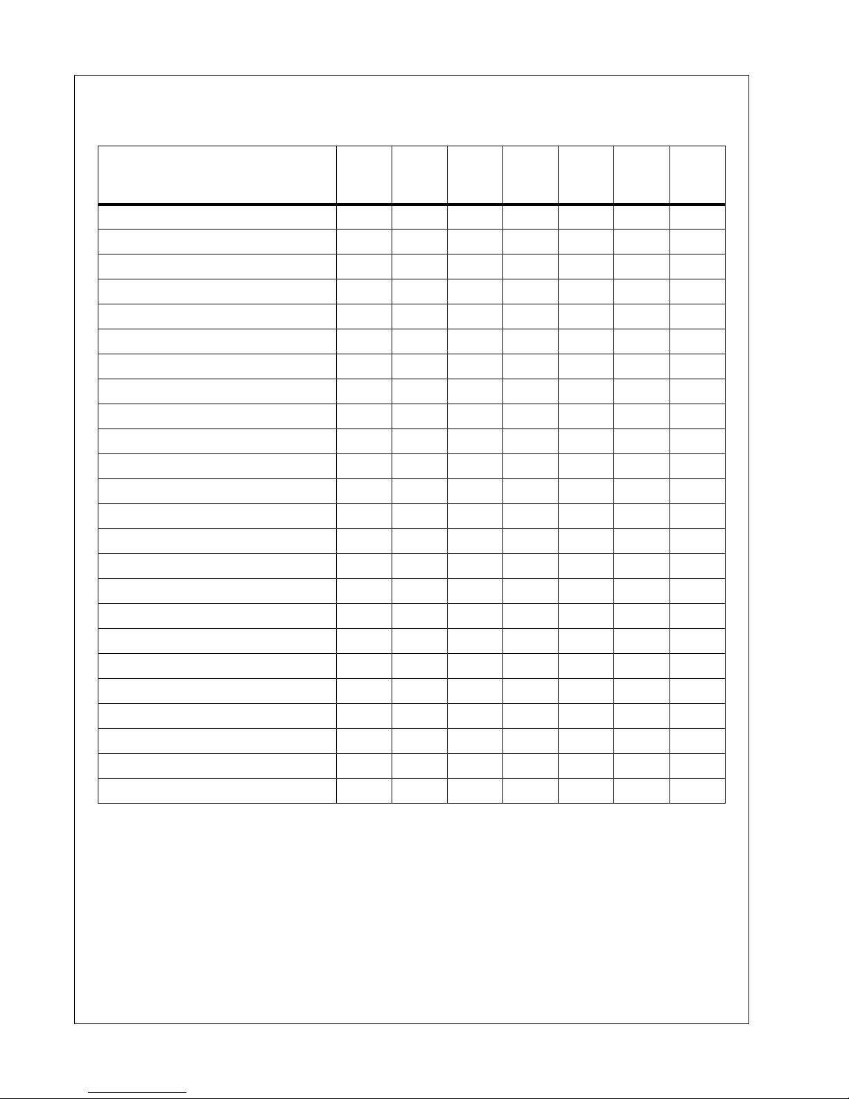
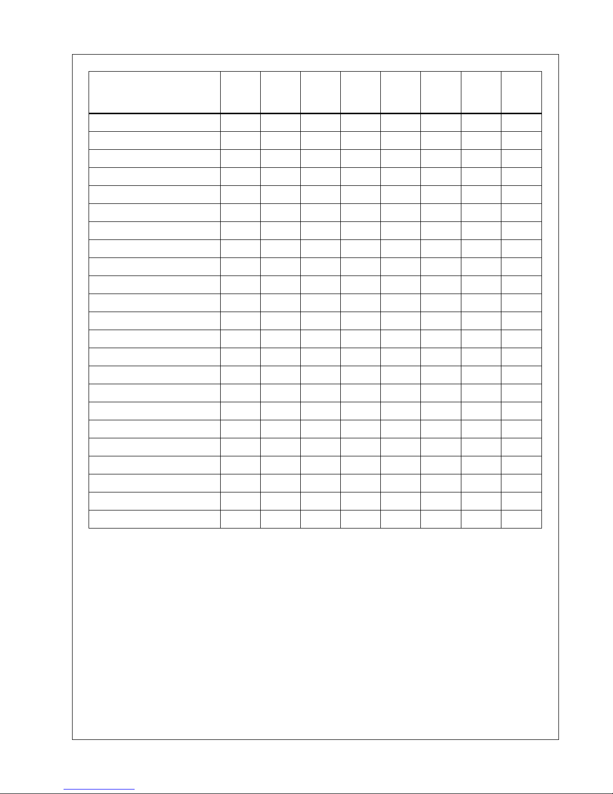
The MAINTENANCE CHART indicates the various components' descriptions and the
intervals when maintenance has to take place. Oil capacities, etc., can be found in the
GENERAL DATA SECTION of this manual.
For any specification or specific requirement on service or preventative maintenance for
the engine, refer to the Engine Section.
Compressed air can be dangerous if incorrectly handled. Before doing any work on the
unit, ensure that all pressure is vented from the system and that the machine cannot be
started accidentally.
If the automatic blowdown fails to operate, then pressure must be gradually relieved by
operating the manual blowdown valve. Suitable personal protective equipment should be
worn.
Ensure that maintenance personnel are adequately trained, competent and have read the
Maintenance Manuals.
44 Book: 23012958 (2-16-07) Rev. A
Page 45

Maintenance Operating & Maintenance Manual
Prior to attempting any maintenance work, ensure that:-
• all air pressure is fully discharged and isolated from the system. If the automatic
blowdown valve is used for this purpose, then allow enough time for it to complete
the operation.
• the discharge pipe / manifold area is depressurized by opening the discharge valve,
while keeping clear of any airflow from it.
!
WARNING
Pressure will remain in the system between the minimum pressure
valve and the service valve after shutdown and operation of the auto
blowdown valve.
This pressure must be relieved by :
(a) Disconnecting any downstream equipment.
(b) Opening the discharge valve to atmosphere.
• the machine cannot be started. Post warning signs and/or fit anti-start devices.
• Disconnect battery cables.
Prior to opening or removing panels or covers to work inside a machine,
ensure that:-
• anyone entering the machine is aware of the reduced level of protection and the
additional hazards, including hot surfaces and intermittently moving parts.
• The machine cannot be started.
Prior to attempting any maintenance work on a running machine, ensure
that:-
• the work carried out is limited to only those tasks which require the machine to
run.
• the work carried out with safety protection devices disabled or removed is limited
to only those tasks which require the machine to be running with safety protection
devices disabled or removed.
• all hazards present are known (e.g. pressurised components, electrically live
components, removed panels, covers and guards, extreme temperatures, inflow
and outflow of air, intermittently moving parts, safety valve discharge etc.).
• appropriate personal protective equipment is worn.
• loose clothing, jewelry, long hair etc. is made safe.
Book: 23012958 (2-16-07) Rev. A 45
Page 46

Operating & Maintenance Manual Maintenance
• warning signs indicating that Maintenance Work is in Progress are posted in a
position that can be clearly seen.
Upon completion of maintenance tasks and prior to returning the machine into
service, ensure that:-
• the machine is suitably tested.
• all guards and safety protection devices are refitted.
• all panels are replaced, canopy and doors closed.
• hazardous materials are effectively contained and disposed of.
Protective Shutdown System
Refer to the diagnostic display codes table for a listing of shutdown conditions.
Low engine fuel level switch.
Test the low engine fuel level switch circuit as follows:
• Start the machine.
NOTE: Do not press the load button.
• Disconnect the switch, the machine should shutdown.
• Re-connect the switch.
Test the low engine fuel level switch by removing and operating the float manually.
!
WARNING
Never remove or replace switches when the machine is running.
Scavenge Line
The scavenge line runs from the combined orifice/drop tube in the separator tank, to the
orifice fitting located in the airend.
Check that the scavenge line and tube are clear of any obstruction each time the
compressor lubricant is changed as any blockage will result in oil carryover into the
discharge air.
46 Book: 23012958 (2-16-07) Rev. A
Page 47

Maintenance Operating & Maintenance Manual
Compressor Oil Filter
Refer to the MAINTENANCE CHART in this section for the recommended servicing
intervals.
Removal
!
WARNING
Do not remove the filter(s) without first making sure that the machine
is stopped and the system has been completely relieved of all air
pressure. (Refer to STOPPING THE MACHINE in the OPERATING
INSTRUCTIONS section of this manual)
Clean the exterior of the filter housing and remove the spin-on element.
lnspection
Inspect the oil filter head to be sure the gasket was removed with the oil filter element.
Clean the gasket seal area on the oil filter head.
!
CAUTION
If there is any indication of the formation of varnishes, shellacs or
lacquers on the filter element, it is a warning that the compressor
lubricating and cooling oil has deteriorated and that it should be
changed immediately. Refer to LUBRICATION later in this section.
NOTICE
Installing a new oil filter element when the old gasket remains on the
filter head, will cause an oil leak and can cause property damage.
Book: 23012958 (2-16-07) Rev. A 47
Page 48

Operating & Maintenance Manual Maintenance
Reassembly
Clean the filter gasket contact area and install the new element.Tighten until the gasket
makes contact with the filter housing. Tighten an additional 1/2 to 3/4 of a revolution.
!
CAUTION
Start the machine (refer to PRIOR TO STARTING and STARTING THE
MACHINE in the OPERATING INSTRUCTIONS section of this manual)
and check for leakage before the machine is put back into service.
Compressor Oil Separator Element
Refer to the MAINTENANCE CHART in this section for the recommended servicing
intervals.
If, however, the element has to be replaced, then proceed as follows:
Removal
!
WARNING
Do not remove the filter(s) without first making sure that the machine
is stopped and the system has been completely relieved of all air
pressure. (Refer to STOPPING THE MACHINE in the OPERATING
INSTRUCTIONS section of this manual).
Disconnect all hoses and tubes from the separator tank cover plate. Remove the drop-tube
from the separator tank cover plate and then remove the cover plate. Remove the
separator element.
lnspection
Examine the filter element. Examine all hoses and tubes, and replace if necessary.
48 Book: 23012958 (2-16-07) Rev. A
Page 49
Maintenance Operating & Maintenance Manual
Reassembly
Thoroughly clean the orifice/drop tube and filter gasket contact area before reassembly.
Install the new element.
!
WARNING
DO not remove the staple from the anti-static gasket on the separator
element since it serves to ground any possible static build-up. Do not
use gasket sealant since this will affect electrical conductance.
Reposition the cover plate, taking care not to damage the gasket, and replace the cover
plate screws tightening in a criss-cross pattern to the recommended torque (refer to the
TORQUE SETTING TABLE later in this section).
Reconnect all hoses and tubes to the separator tank cover plate.
Replace the compressor oil (refer to LUBRICATION later in this section).
!
CAUTION
Start the machine (refer to PRIOR TO STARTING and STARTING THE
MACHINE in the OPERATING INSTRUCTIONS section of this manual)
and check for leakage before the machine is put back into service.
Compressor Oil Cooler and Engine Radiator
When grease, oil and dirt accumulate on the exterior surfaces of the oil cooler and radiator,
the efficiency is impaired. It is recommended that each month the oil cooler and radiator
be cleaned by directing a jet of compressed air, (carrying if possible a non-flammable
cleaning solvent) over the exterior core of the cooler/radiator. This should remove any
accumulation of oil, grease and dirt from the exterior core of the cooler so that the entire
cooling area can radiate the heat of the lubricating and cooling oil/water into the air stream.
!
WARNING
Hot engine coolant and steam can cause injury. When adding coolant
or antifreeze solution to the engine radiator, stop the engine at least
one minute prior to releasing the radiator filler cap. Using a cloth to
protect the hand, slowly release the filler cap, absorbing any released
fluid with the cloth. Do not remove the filler cap until all excess fluid is
released and the engine cooling system fully depressurised.
Book: 23012958 (2-16-07) Rev. A 49
Page 50
Operating & Maintenance Manual Maintenance
!
WARNING
Follow the instructions provided by the antifreeze supplier when
adding or draining the antifreeze solution. It is advisable to wear
personal protective equipment to prevent skin and eye contact with
the antifreeze solution.
Air Filter Elements
The air filter element should be replaced regularly (refer to the MAINTENANCE CHART)
or when the restriction indicator shows red, whichever comes first. The aircleaner
precleaner dumps should be cleaned as indicated in the MAINTENANCE CHART (more
frequently in dusty operating conditions).
Removal
!
CAUTION
Never remove and replace element(s) when the machine is running.
Clean the exterior of the filter housing and remove the filter element by releasing the nut.
Reassembly
Assemble the new element into the filter housing ensuring that the seal seats properly.
Secure element by tightening nut.
Before restarting the machine, check that all clamps are tight.
Ventilation
Always check that the air inlets and outlets are clear of debris etc.
Cooling Fan Drive
Periodically check that the fan mounting bolts in the fan hub have not loosened. If, for any
reason, it becomes necessary to remove the fan or re-tighten the fan mounting bolts, apply
a good grade of commercially available thread locking compound to the bolt threads and
tighten to the torque value shown in the TORQUE SETTING TABLE later in this section.
The fan belt(s) should be checked regularly for wear and correct tensioning.
50 Book: 23012958 (2-16-07) Rev. A
Page 51

Maintenance Operating & Maintenance Manual
Fuel System
The fuel tank should be filled daily or every eight hours. To minimise condensation in the
fuel tank(s), it is advisable to top up after the machine is shut down or at the end of each
working day. Drain any sediment or condensate that may have accumulated in the tank(s).
Refer to MAINTENANCE CHART.
Fuel Filter Water Separator
The fuel filter water separator contains a filter element which should be replaced at regular
intervals (see the SERVICE/MAINTENANCE CHART).
Hoses
All components of the engine cooling air intake system should be checked periodically to
keep the engine at peak efficiency.
At the recommended intervals, (see the MAINTENANCE CHART), inspect all of the intake
lines to the air filter, and all flexible hoses used for air lines, oil lines and fuel lines.
Periodically inspect all pipework for cracks, leaks, etc. and replace immediately if
damaged.
Electrical System
!
WARNING
Disconnect the battery cables before performing any maintenance or
service.
Check the security of electrical terminals on the switches and relays i.e. nuts or screws
loose, which may cause local hot spot oxidation.
Inspect the components and wiring for signs of overheating i.e. discolouration, charring of
cables, deformation of parts, acrid smells and blistered paint.
Battery
Keep the battery terminals and cable clamps clean and lightly coated with petroleum jelly
to prevent corrosion.
The battery restraint should be kept tight enough to prevent the battery from moving.
Book: 23012958 (2-16-07) Rev. A 51
Page 52

Operating & Maintenance Manual Maintenance
Pressure System
Regularly, it is necessary to inspect the external surfaces of the system (from the airend
through to the discharge valve(s)) including hoses, tubes, tube fittings and the separator
tank, for visible signs of impact damage, excessive corrosion, abrasion, tightness and
chafing. Any suspect parts should be replaced before the machine is put back into service.
Tire Pressure
See the GENERAL DATA SECTION of this manual.
Running Gear/wheels
Check the wheel nut torque 20 miles (30 kilometres) after refitting the wheels. Refer to the
TORQUE SETTING TABLE later in this section.
Lifting jacks should only be used under the axle
The bolts securing the running gear to the chassis should be checked periodically for
tightness (refer to the MAINTENANCE CHART for frequency) and re-tighten where
necessary. Refer to the TORQUE SETTING TABLE later in this section.
Lubrication
!
CAUTION
Always check the oil levels before a new machine is put into service.
If, for any reason, the unit has been drained, it must be re-filled with new oil before it is put
into operation.
Engine Lubricating Oil
The engine oil and oil filter element should be changed at the engine manufacturer's
recommended intervals. Refer to the Engine operator manual/section.
Refer to the Engine operators' manual/section for engine oil specifications.
52 Book: 23012958 (2-16-07) Rev. A
Page 53
Maintenance Operating & Maintenance Manual
Compressor Lubricating Oil
Refer to the MAINTENANCE CHART in this section for service intervals.
NOTE: If the machine has been operating under adverse conditions, or
has suffered long shutdown periods, then more frequent service
intervals will be required.
!
WARNING
DO NOT, under any circumstances, remove any drain plugs or the oil
filler-plug from the compressor lubricating and cooling system
without first making sure that the machine is stopped and the system
has been completely relieved of all air pressure (refer to STOPPING
THE MACHINE in the OPERATING INSTRUCTIONS section of this
manual).
Completely drain the receiver/separator system including the piping and oil cooler by
removing the drain plug(s) and collecting the used oil in a suitable container.
Replace the drain plug(s) ensuring that each one is secure.
NOTE: If the oil is drained immediately after the machine has been
running, then most of the sediment will be in suspension and will
therefore drain more readily.
!
CAUTION
Some oil mixtures are incompatible and result in the formation of
varnishes, shellacs or lacquers which may be insoluble. Refer to
Portable Compressor Fluid Chart.
Running Gear Wheel Bearings
Wheel bearings should be packed with grease every 12 months. The type of grease used
should conform to specification MIL-G-10924.
Book: 23012958 (2-16-07) Rev. A 53
Page 54

**Always use Ingersoll-Rand Replacement parts!**
54 Book: 23012958 (2-16-07) Rev. A
Page 55

Lubrication
Book: 23012958 (2-16-07) Rev. A 55
Page 56

Operating & Maintenance Manual Lubrication
Lubrication
General Information
Lubrication is an essential part of preventive maintenance, affecting to a great extent the
useful life of the unit. Different lubricants are needed and some components in the unit require
more frequent lubrication than others. Therefore, it is important that the in structions regarding
types of lubricants and the frequency of their application be explicitly followed. Periodic
lubrication of the moving parts reduces to a minimum the possibility of mechanical failures.
The Preventive Maintenance Schedule shows those items requiring regular service and the
interval in which they should be performed. A regular service program should be developed to
include all items and fluids. These intervals are based on average operating conditions. In the
event of extremely severe (hot, cold, dusty or wet) operating conditions, more frequent
lubrication than specified may be necessary. Details concerning lubrication of the running gear
are in Maintenance Section.
All filters and filter elements for air and compressor lubricant must be obtained through
Ingersoll-Rand to assure the proper size and filtration for the compressor.
Compressor Oil Change
These units are normally furnished with an initial supply of oil sufficient to allow operation of
the unit for approximately 6 months or 1000 hours, whichever comes first. If a unit has been
completely drained of all oil, it must be refilled with new oil before it is placed in operation.
Refer to specifications in Lubrication Table.
NOTICE
Some oil types are incompatible when mixed and result in the formation
of varnishes, shellacs, or lacquers which may be insoluble. Such
deposits can cause serious troubles including clogging of the filters.
Where possible, do NOT mix oils of different types and avoid mixing
different brands. A type or brand change is best made at the time of a
complete oil drain and refill.
If the unit has been operated for the time/hours mentioned above, it should be completely
drained of oil. If the unit has been operated under adverse conditions, or after long periods in
storage, an earlier change period may be necessary as oil deteriorates with time as well as by
operating conditions.
56 Book: 23012958 (2-16-07) Rev. A
Page 57

Lubrication Operating & Maintenance Manual
!
WARNING
High pressure air can cause severe injury or death from hot oil and flying
parts. Always relieve pressure before removing caps, plugs, covers or
other parts from pressurized air system. Ensure the following conditions
are met:
— Discharge air pressure gauge reads zero (0).
— No air discharging from an “open” manual blowdown valve.
An oil change is good insurance against the accumulation of dirt, sludge, or oxidized oil
products.
Completely drain the reservoir, piping, and cooler. If the oil is drained immediately after the
unit has been run for some time, most of the sediment will be in suspension and, therefore,
will drain more readily. However, the fluid will be hot and care must be taken to avoid contact
with the skin or eyes.
After the unit has been completely drained of all old fluid, close the drain valve, install new oil
filter elements. Add oil in the specified quantity at the filler plug. Tighten the filler plug and run
the machine to circulate the oil. Check the oil level. DO NOT OVERFILL.
NOTICE
Ingersoll-Rand provides compressor oil specifically formulated for
Portable Compressors and requires the use of these fluids in order to
obtain extended limited airend warranty.
Book: 23012958 (2-16-07) Rev. A 57
Page 58
Operating & Maintenance Manual Lubrication
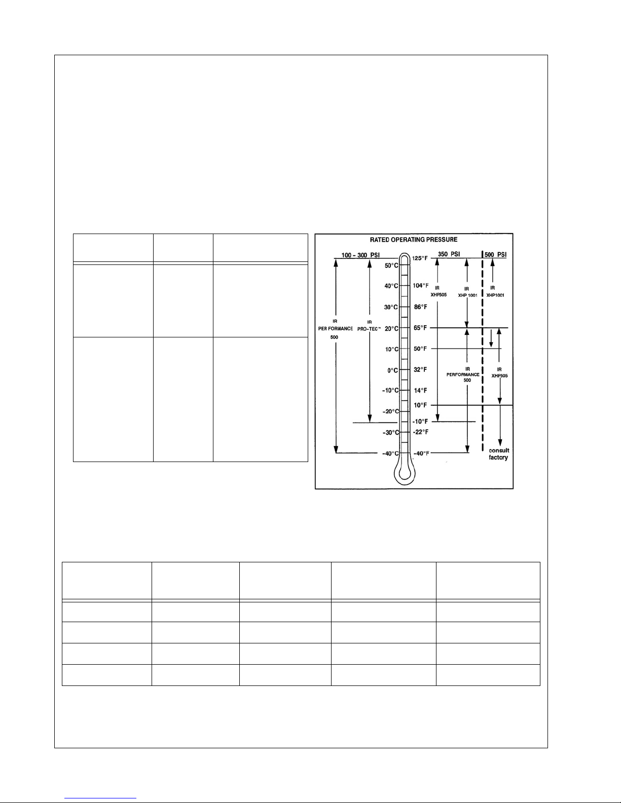
Portable Compressor Fluid Chart
Refer to these charts for correct compressor fluid required. Note that the selection of fluid is
dependent on the design operating pressure of the machine and the ambient temperature
expected to be encountered before the next oil change.
NOTE: Fluids listed as “preferred” are required for extended warranty.
Compressor oil carryover (oil consumption) may be greater with th e use of alternative
fluids.
Design Operating
Pressure
100 psi to 300 psi
350 psi
Ambient
Temperature
-10°F to 125°F
(-23°C to 52°C)
-10°F to 125°F
(-23°C to 52°C)
65°F to 125°F
(18°C to 52°C)
Specification
Preferred:
IR Pro-Tec™
Alternate:
ISO Viscosity Grade 46
with rust and oxidation
inhibitors, designed for
air compressor service.
Preferred:
IR XHP 605
Alternate:
IR XHP405
ISO Viscosity Grade 68
Group 3 or 5 with rust and
oxidation inhibitors
designed for air
compressor service.
Preferred:
XHP605
IR XHP1001
Preferred Ingersoll-Rand Fluids - Use of these
fluids with original I-R filters can extend airend warranty. Refer to operator’s manual warranty
section for details or contact your I-R representative.
Ingersoll-Rand
Preferred Fluids
1 gal. (3.8 Litre) 5 gal. (19.0 Litre) 55 gal. (208.2 Litre) 220 gal. (836 Llitre)
IR Pro-Tec™ 36899698 36899706 36899714 36899722
IR XHP605 - 22252076 22252050 22252068
IR XHP1001 - 35612738 35300516 XHP405 - 22252126 22252100 22252118
58 Book: 23012958 (2-16-07) Rev. A
Page 59
©2004 Ingersoll-Rand Company, Printed in the USA
 Loading...