

Page 1
OPERATOR’S MANUAL
)
INCLUDING:ĂOPERATION,ĂINSTALLATIONĂ&ĂMAINTENANCE Released: 08-28-72
SECTION M10
MANUAL 25
Revised: 01-14-00
MODELS: 7980–( )–( )
85,000 R.P.M. TURBINE GRINDER
ARO is not responsible for customer modification of tools for applications on which ARO
was not consulted.
IMPORTANT SAFETY INFORMATION ENCLOSED.
READ THIS MANUAL BEFORE OPERATING TOOL.
IT IS THE RESPONSIBILITY OF THE EMPLOYER TO PLACE THE INFORMATION
IN THIS MANUAL INTO THE HANDS OF THE OPERATOR.
FAILURE TO OBSERVE THE FOLLOWING WARNINGS COULD RESULT IN INJURY.
PLACING TOOL IN SERVICE
• Always operate, inspect and maintain this tool
in accordance with American National
Standards Institute Safety Code for Portable
Air Tools (ANSI B186.1).
• For safety, top performance, and maximum
durability of parts, operate this tool at 90 psig
(6.2 bar/620 kPa) maximum air pressure at the
inlet with 3/16” (5 mm) inside diameter air
supply hose.
• Always turn off the air supply and disconnect
the air supply hose before installing, removing
or adjusting any accessory on this tool, or
before performing any maintenance on this
tool.
• Do not use damaged, frayed or deteriorated
air hoses and fittings.
• Be sure all hoses and fittings are the correct
size and are tightly secured. See Dwg.
TPD905–1 for a typical piping arrangement.
• Always use clean, dry air at 90 (6.2 bar/
620 kPa) psig maximum air pressure. Dust,
corrosive fumes and/or excessive moisture
can ruin the motor of an air tool.
• Do not lubricate tools with flammable or
volatile liquids such as kerosene, diesel or jet
fuel.
• Do not remove any labels. Replace any
damaged label.
USING THE TOOL
• Always wear eye protection when operating or
performing maintenance on this tool.
• Always wear hearing protection when
operating this tool.
• Keep hands, loose clothing and long hair
away from rotating end of tool.
• Anticipate and be alert for sudden changes in
motion during start up and operation of any
power tool.
• Keep body stance balanced and firm. Do not
overreach when operating this tool. High
reaction torques can occur at or below the
recommended air pressure.
• Tool accessories may continue to rotate
briefly after throttle is released.
• Air powered tools can vibrate in use.
Vibration, repetitive motions or uncomfortable
positions may be harmful to your hands and
arms. Stop using any tool if discomfort,
tingling feeling or pain occurs. Seek medical
advice before resuming use.
• Use accessories recommended by ARO.
• This tool is not designed for working in
explosive atmospheres.
• This tool is not insulated against electric
shock.
The use of other than genuine ARO replacement parts may result in safety hazards, decreased tool
performance, and increased maintenance, and may invalidate all warranties.
Repairs should be made only by authorized trained personnel. Consult your nearest ARO Authorized
Servicenter.
For parts and service information, contact your local ARO distributor, or the Customer Service Dept. of the Ingersoll–Rand
Distribution Center, White House, TN at PH: (615) 672–0321, FAX: (615) 672–0801.
ARO Tool Products
Ingersoll–Rand Company
1725 U.S. No. 1 North D P.O. Box 8000 D Southern Pines, NC 28388–8000
E2000 INGERSOLL–RAND COMPANY D PRINTED IN U.S.A.
Page 2
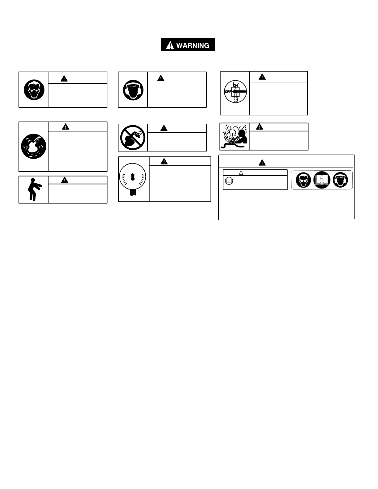
WARNING LABEL IDENTIFICATION
FAILURE TO OBSERVE THE FOLLOWING WARNINGS COULD RESULT IN INJURY.
M10
25
WARNING
Always wear eye protection
when operating or performing maintenance on this
tool.
WARNING
Air powered tools can vibrate
in use. Vibration, repetitive
motions or uncomfortable positions may be harmful to your
hands and arms. Stop using
any tool if discomfort, tingling
feeling or pain occurs. Seek
medical advice before resuming use.
90 psig
(6.2bar/620kPa)
WARNING
Always wear hearing
protection when operating
this tool.
WARNING
Do not carry the tool by
the hose.
WARNING
Operate at 90 psig (6.2 bar/
620 kPa) Maximum air pressure.
WARNING
Keep body stance balanced
and firm. Do not overreach
when operating this tool.
GRINDER SPECIFIC WARNINGS
• Do not use this tool if actual free speed
exceeds the nameplate rpm.
• Before mounting a wheel, after any tool repair
or whenever a Grinder is issued for use, check
free speed of Grinder with a tachometer to
make certain its actual speed at 90 psig (6.2
bar/620 kPa) does not exceed rpm stamped or
printed on the nameplate. Grinders in use on
the job must be similarly checked at least
once each shift.
• Always use the recommended ARO Wheel
Guard furnished with the Grinder.
• Do not use any grinding wheel, bur or other
accessory having a maximum operating speed
less than the free speed of the Grinder in
which it is being used. Always conform to
maximum rpm on grinding wheel blotters.
• Inspect all grinding wheels for chips or cracks
prior to mounting. Do not use a wheel that is
chipped or cracked or otherwise damaged. Do
not use a wheel that has been soaked in water
or any other liquid.
• Make certain grinding wheel properly fits the
arbor. Do not use reducing bushings to adapt
a wheel to any arbor unless such bushings
are supplied by and recommended by the
wheel manufacturer.
• After mounting a new wheel, hold the Grinder
under a steel workbench or inside a casting
and run it for at least 60 seconds. Make
certain no one is within the operating plane of
WARNING
Always turn off the air supply and disconnect the air
supply hose before installing, removing or adjusting
any accessory on this tool,
or before performing any
maintenance on this tool.
WARNING
Do not use damaged, frayed
or deteriorated air hoses
and fittings.
WARNING
WARNING
Read the manual before
operating this tool.
Operate at 90 psig/6.2 bar max.
PN 48176–1 LABEL
(NON–EU MODELS)
This label must appear on the tool at all times. If it is lost or
damaged, a replacement label is available at no cost.
the grinding wheel. If a wheel is defective,
improperly mounted or the wrong size and
speed, this is the time it will usually fail.
• When starting with a cold wheel, apply it to
the work slowly until the wheel gradually
warms up. Make smooth contact with the work
and avoid any bumping action or excessive
pressure.
• Always replace a damaged, bent or severely
worn wheel guard. Do not use a wheel guard
that has been subjected to a wheel failure.
• Make certain wheel flanges are at least 1/3 the
diameter of grinding wheel, free of nicks,
burrs and sharp edges. Always use wheel
flanges furnished by the manufacturer; never
use a makeshift flange or a plain washer.
Tighten Flange Nut securely.
• Guard opening must face away from operator.
Bottom of wheel must not project beyond
guard.
• Always use a wheel blotter between each
wheel flange and the wheel. The blotters must
be at least as large in diameter as the wheel
flanges.
• Do not attempt to disassemble the Controller.
The Controller is available only as a unit and
is guaranteed for the life of the tool if it is not
abused.
• Before installing a new Cylinder Case
Assembly, always select the correct Assembly
for the motor package you are using.
PN 49883 LABEL
(–EU MODELS)
2
Page 3
LUBRICATION
Where Used
“O” Rings 36460 4 oz. Stringy
Bearings 33153 5 lb. ‘‘EP” – NLGI
ARO Part # Description
Lubricant
#1 Grease
M10
25
Do not mark any nonmetallic surface on this tool
with customer identification codes. Such actions
could affect tool performance.
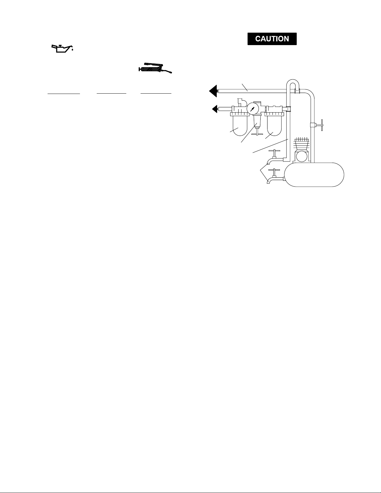
MAIN LINES 3 TIMES
AIR TOOL INLET SIZE
TO
AIR
SYSTEM
TO
AIR
TOOL
Always use an air line lubricator with these tools.
We recommend the following Filter–Lubricator–
Regulator Unit:
ARO Model P29231–110
Lack of or an excessive amount of lubrication will
affect the performance and life of this tool. Use only
recommended lubricants.
LUBRICATOR
REGULATOR
BRANCH LINE 2 TIMES
AIR TOOL INLET SIZE
DRAIN REGULARLY
FILTER
COMPRESSOR
(Dwg. TPD905–1)
3
Page 4

181925 24 23 22 21 20
34 33 32 29 28 27 26
NOT SHOWN
30131 WRENCH
04662532 WARNING LABEL (NON–EU MODELS)
39853 HOSE ASSEMBLY
48176–1 WARNING LABEL (NON–EU MODELS)
49883 WARNING LABEL (–EU MODELS)
PART NUMBER FOR ORDERING PART NUMBER FOR ORDERING
1 Nut 36906. . . . . . . . . . . . . . . . . . . . . . . . . . . . . . . .
2a Throttle and Bushing Assembly . . . . . . . .
2b Head Assembly . . . . . . . . . . . . . . . . . . . . . .
2 Head and Throttle Assembly (includes
items 2a and 2b)
for non ‘‘–EU” models 36920–1. . . . . . . . . . . . . . . .
for ‘‘–EU” models 49939–1. . . . . . . . . . . . . . . . . . .
3 ‘‘O” Ring (2 req’d) Y325–15. . . . . . . . . . . . . . . . . . . .
4 Roll Pin 36918. . . . . . . . . . . . . . . . . . . . . . . . . . . . .
Head and Throttle Assembly (includes
items 1 thru 4)
for non‘‘–EU” models 36920. . . . . . . . . . . . . . . .
for ‘‘–EU” models 49939. . . . . . . . . . . . . . . . . . .
5 Lever 43885. . . . . . . . . . . . . . . . . . . . . . . . . . . . . . .
6 Roll Pin Y178–44. . . . . . . . . . . . . . . . . . . . . . . . . . . . .
7 Throttle Valve Head 38947. . . . . . . . . . . . . . . . . .
8 ‘‘O” Ring Y325–211. . . . . . . . . . . . . . . . . . . . . . . . . . . .
9 ‘‘O” Ring Y325–5. . . . . . . . . . . . . . . . . . . . . . . . . . . .
10 Stem V alve 33032. . . . . . . . . . . . . . . . . . . . . . . . . .
11 Spring 31125. . . . . . . . . . . . . . . . . . . . . . . . . . . . . .
12 Seal 32886. . . . . . . . . . . . . . . . . . . . . . . . . . . . . . . .
13 Throttle V alve Screw 33023. . . . . . . . . . . . . . . . . .
Head Assembly (includes items 7 thru 13) 38949–1
14 Lever 45952. . . . . . . . . . . . . . . . . . . . . . . . . . . . . . .
15 Roll Pin Y178–5. . . . . . . . . . . . . . . . . . . . . . . . . . . . .
16 Spring 45778. . . . . . . . . . . . . . . . . . . . . . . . . . . . . .
17 Arm 45777. . . . . . . . . . . . . . . . . . . . . . . . . . . . . . . .
Lever Assembly (includes items 14 thru 17) 45953. . . . .
18 Nozzle Plate 36907. . . . . . . . . . . . . . . . . . . . . . . .
19 Nut 32798. . . . . . . . . . . . . . . . . . . . . . . . . . . . . . . .
20 Sleeve 36908. . . . . . . . . . . . . . . . . . . . . . . . . . . . .
21 Impeller 36909. . . . . . . . . . . . . . . . . . . . . . . . . . . . .
22 Impeller 36910. . . . . . . . . . . . . . . . . . . . . . . . . . . . .
23 Ball Bearing 36913. . . . . . . . . . . . . . . . . . . . . . . . .
24 Impeller 36911. . . . . . . . . . . . . . . . . . . . . . . . . . . . .
25 Spacer 36919. . . . . . . . . . . . . . . . . . . . . . . . . . . . .
26 Housing
for non ‘‘–EU” models 36901. . . . . . . . . . . . . . . .
for ‘‘–EU” models 49901. . . . . . . . . . . . . . . . . . . .
27 Ball Bearing 36913. . . . . . . . . . . . . . . . . . . . . . . . .
28 Spindle 36902. . . . . . . . . . . . . . . . . . . . . . . . . . . . .
29 Lock Sleeve 43881. . . . . . . . . . . . . . . . . . . . . . . . .
32 Housing Cap 36912. . . . . . . . . . . . . . . . . . . . . . . .
33 Collet 31812–4. . . . . . . . . . . . . . . . . . . . . . . . . . . . . .
34 Nosepiece 36914. . . . . . . . . . . . . . . . . . . . . . . . . .
Page 5

12a342b
MODEL 7980–A–( )
5
78
6
MODEL 7980–2
14151617
9
10
MODEL 7980–2–EU
11
12
13
DISASSEMBLY/ASSEMBLY INSTRUCTIONS
NOTICE
• Never apply excessive pressure by a holding device which
may cause distortion of a part.
• Apply pressure evenly to parts which have a press fit.
• Apply even pressure to the bearing race that will be press
fitted to the mating part.
• Use correct tools and fixtures when servicing this tool.
• Don’t damage ‘‘O” rings when servicing this tool.
• Use only genuine ARO replacement parts for this tool. When
ordering, specify part number, description, tool model number
and serial number.
DISASSEMBLY
_ Remove hose assembly (not shown) from the inlet of the tool.
_ Insert A 1/8” diameter pin thru the hole in the housing (26), lock
sleeve (29) and spindle (28).
_ Using a wrench on flats of housing cap (32), unthread and re-
move housing cap (32) and lock sleeve (29).
_ Using a wrench on flats of nosepiece (34), unthread and re-
move from spindle, releasing collet (33).
• Models 7980–2–( ) – Place head (7) in a vise and, using a
strap type wrench, unthread and remove housing (26).
• Models 7980–A–( ) – Clamp wrench (30131) flatwise in a vise
and place slot in air inlet of tool on wrench. Using a strap type
wrench, unthread and remove housing (26).
_ Remove nozzle plate (18).
_ Insert a 1/8” diameter pin thru the hole in housing (26) and
spindle (28), and remove nut (19).
_ Press spindle (28) out nose end of housing.
_ Remove impellers (21, 22 and 24), sleeve (20), bearing (23)
and spacer (25) from housing.
_ Do not remove bearing (27) from spindle unless damage is ev-
ident. To remove, press off of spindle.
• Models 7980–2–( ) – Remove valve screw ( 13) and sea l (1 2),
releasing spring (11), stem valve (10) and ‘‘O” ring (9).
• Models 7980–A–( ) – To remove ‘‘O” rings (3), remove nut (1),
releasing throttle and bushing assembly (2a).
ASSEMBLY
_ Assemble bearing (27) to spindle (28), pressing on inner race
of bearing.
_ Assemble spindle into housing theu nose end, pressing on
outer race of bearing.
_ Assemble spacer (25), impeller (24), impeller (22) with bear-
ing (23) and impeller (21) with sleeve (20) to spindle, securing
with nut (19). NOTE: Assemble impellers with grooves in the
direction shown on page 4.
_ Assemble nozzle plate (18) and head to tool.
_ Assemble lock sleeve (29) to housing, aligning hole in lock
sleeve (29) with hole in housing.
_ Insert a 1/8” diameter pin thru hole in housing and lock sleeve
(29).
_ Assemble housing cap (32) to housing, tightening securely.
_ Assemble collet (33) and nosepiece (34) to spindle.
• Models 7980–2–( ) – Grease and assemble ‘‘O” ring (9) to
stem valve (10). Assemble stem valve (10) and spring (1 1 ) to
head, securing with seal (12) and valve screw (13).
6
Page 6

TYPICAL CROSS SECTION OF TOOL
M10
25
MODEL 7980–2 MODEL 7980–A–( )
7
Page 7

TYPICAL CROSS SECTION OF TOOL
MODEL 7980–2–EU
8
Page 8

PN 4999–482
 Loading...