

Page 1
SECTION
OPERATOR’S MANUAL
INCLUDING: OPERATION, INSTALLATION & MAINTENANCE
Tool Products
“2200” SERIES SHORT GRINDERS
MANUAL
Released: 5/79
Revised:
Form: 1558-2
Models: 7870-F-( ), 7871-F-( ),
7872-F and 7873-F.
READ THIS MANUAL CAREFULLY BEFORE INSTALLING,
OPERATING OR SERVICING THIS EQUIPMENT.
FAILURE TO OBSERVE THE FOLLOWING WARNINGS COULD RESULT IN INJURY.
M10
58
3-10-95
To aid the operator’s understanding of proper and safe use of
grinders, the publications, “Use, Care and Protection of Abrasive
Wheels”, A.N.S.I. B7.1, and “Safety Code for Portable Air Tools”,
A.N.S.I. 8188.1, can be purchased from:
American National Standards Institute, Inc.
1430 Broadway
New York, New York 10018
l
Operate this tool at 90 p.s.i.g. (8.2 bar) maximum air pressure
at the air inlet of the tool.
l
Disconnect air supply from tool before removing/installing
wire brush or rotary file or performing other maintenance procedures.
l
Keep hands, clothing and long hair away from rotating end of
tool.
l
Anticipate and be alert for sudden changes in motion during
start up and operation of any power tool.
l
Never exceed rated r.p.m. of tool.
l
Wear suitable eye and hearing protection while operating tool.
l
Tool shaft can continue to rotate briefly after throttle is released.
l
Do not lubricate tools with flammable or volatile liquids such as
kerosene, diesel or jet fuel.
l
Use tool only for purposes for which it was intended.
Do not use excessive work pressure.
l
Do not remove any labels. Replace any damaged label.
l
Use only accessories recommended by ARO.
l
Repeated prolonged operator exposure to vibrations which may
be generated in the use of certain hand-held tools may produce
Raynaud’s phenomenon, commonly referred to as Whitefinger
disease. The phenomenon produces numbness and burning
sensations in the hand and may cause circulation and nerve dam-
age as well as tissue necrosis. Repetitive users of hand-held
tools who experience vibrations should closely monitor duration
of use and their physical condition.
l
The use of other than genuine ARO replacement parts may
result in safety hazards, decreased tool perfomance and increased maintenance and may invalidate all warranties.
l
ARO is not responsible for customer modification of tools for
applications on which ARO was not consulted.
l
Tool maintenance and repair should be performed by author&d. trained, competent personnel. Consult your nearest
ARO authorized servicenter.
l
It is the responsibility of the employer to place the information
in this manual into the hands of the operator.
For parts and service information, contact your local ARO distributor, or the Customer Service Dept. of the Ingersoll-Rand Distribution
Center, White House, TN at PH: (815) 672-0321, FAX: (615) 672-0601.
ARO Tool Products
Ingersoll-Rand Company
1725 U.S. No. 1 North l PO. Box 8000 l Southern Pines, NC 26388-8000
©1985 THE ARO CORPORATlON PRINTED IN USA
Page 2
FAILURE TO OBSERVE THE FOLLOWING WARNINGS COULD RESULT IN INJURY.
I
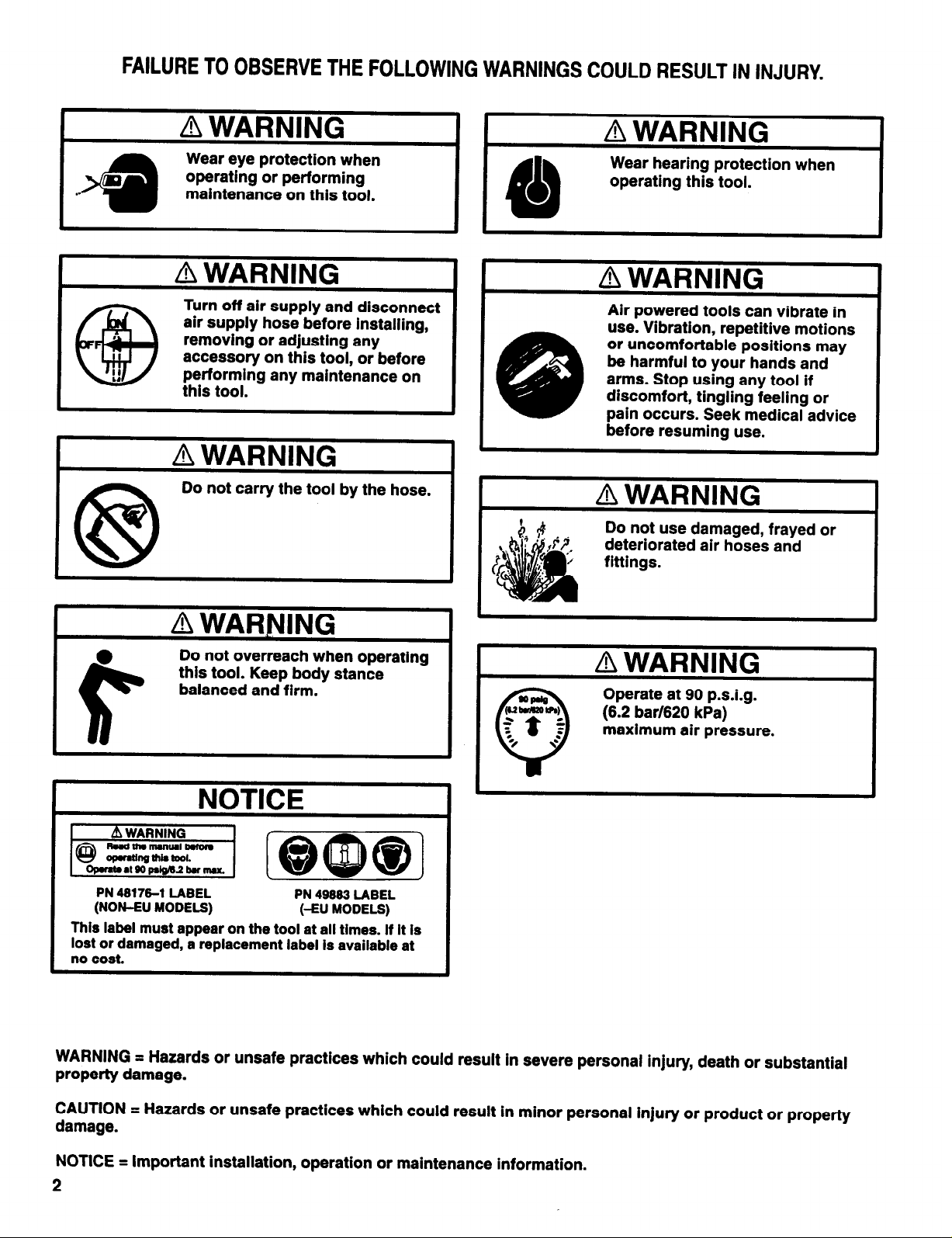
Wear hearing protection when
operating this tool.
Turn off air supply and disconnect
air supply hose before installing,
removing or adjusting any
accessory on this tool, or before
performing any maintenance on
this tool.
Do not carry the tool by the hose.
Do not overreach when operating
this tool. Keep body stance
balanced and firm.
Air powered tools can vibrate
use. Vibration, repetitive motions
or uncomfortable positions may
be harmful to your hands and
arms. Stop using any tool if
discomfort, tingling feeling or
pain occurs. Seek medical advice
before resuming use.
Do not use damaged, frayed or
deteriorated air hoses and
fittings.
Operate at 90 p.s.i.g.
(6.2 bar/620 kPa)
maximum air pressure.
in
I
PN 48176-1 LABEL PN 49883 LABEL
(NON-EU
This label must appear on the tool at all times. If It Is
lost or damaged, a replacement label is available at
no cost.
WARNING = Hazards or unsafe practices which could result in severe personal injury, death or substantial
property damage.
CAUTION = Hazards or unsafe practices which could result in minor personal injury or product or property
damage.
NOTICE = Important installation, operation or maintenance information.
NOTICE
MODELS)
(-EU MODELS)
2
Page 3
ROUTINE LUBRICATION REQUIREMENTS
M10
58
Lack of or an excessive amount of lubrication will affect the performance and life of this tool. Use only recommended lubricants at
below time intervals:
EVERY 8 HOURS OF TOOL OPERATION - Fill lubricator reser-
voir of recommended F.R.L. with spindle oil (29665). if an in line or
air line lubricator is not used, apply several drops of spindle oil
(29685) in air inlet.
EVERY 40 HOURS OF TOOL OPERATION - Flush tool with a
solution of three (3) parts cleaning solvent to one (1) part spindle
oil. After flushing, apply a small amount of spindle oil in air inlet and
run tool for one minute to insure proper lubrication.
AIR SUPPLY REQUIREMENTS
For maximum operating efficiency, the following air supply specifi-
cations should be maintained to this air tool:
l
AIR PRESSURE - 90 p.s.i.g. (6.2 bar)
l
AIR FILTRATION - 50 micron
l
LUBRICATED AIR SUPPLY
l
HOSE SIZE - 3/8” (10 mm) I.D.
An ARO@ model C28231-810 air line FiLTER/REGULATOR/LUBRICATOR (F.R.L.) is recommended to maintain the above air
supply specifications.
RECOMMENDED LUBRICANTS
trained, competent personnel. Tools, hose and fittings shall be replaced if unsuitable for safe operation and responsibility should
be assigned to be sure that all tools requiring guards or other safety devices shall be kept in legible condition. Maintenance and repair records should be maintained on all tools. Frequency of
repair and the nature of the repairs can reveal unsafe application.
Scheduled maintenance by competent authorized personnel
should detect any mistreatment or abuse of the tool and worn
parts. Corrective action should be taken before returning the tool
for use.
Disassembly should be done on a clean work bench with a clean
cloth spread to prevent the loss of small parts. After disassembly
is completed, all parts should be thoroughly washed in a clean solvent, blown dry with air and inspected for wear levels, abuse and
contamination. Double sealed or shielded bearings should never
be placed in solvent unless a good method of re-lubricating the
bearing is available. Open bearings may be washed but should
not be allowed to spin while being blown dry.
Upon reassembling, lubricate parts where required. Use 33153
grease, or equivalent, in beatings. Use 36460 lubricant for “0”
ring assembly. When assembling “0” rings or parts adjacent “0”
rings, care must be exercised to prevent damage to the rubber
sealing surfaces. A small amount of grease will usually hold steel
bails and other small parts in place while assembling.
Before mounting a wheel, after all tool repairs and whenever a
grinder is issued for use, the speed of the grinder shall be checked
with a tachometer to make certain that its actual speed does not
exceed its rated speed.
After disassembly is complete, all parts, except sealed or shielded
bearings, should be washed with solvent. To relubricate parts, or
for routine lubrication, use the following recommended lubricants:
Where ARO
Description
Air Motor 29665 1 qt Spindle Oil
“0” Rings & Lip Seals 36460 4 oz. Stringy Lubricant
Gears and Bearings 33153 5 lb. “EP’ - NLGI #1 Grease
INSPECTION, MAINTENANCE AND INSTALLATION
Disconnect air supply from the tool or shut off air supply and exhaust (drain) line of compressed air before performing maintenance or service to the tool.
It is important that the tools be serviced and inspected at regular
intervals for maintaining safe, trouble-free operation of the tool.
Be sure the tool is receiving adequate lubrication, as failure to lubricate can create hazardous operating conditions resulting from
excessive wear.
Be sure that the air supply lines and connectors are of proper size
to provide a sufficient quantity of air to the tool.
Safety guards shall be in good functional condition. Damaged,
bent or severely worn guards shall be replaced. A guard which
has been subjected to a wheel failure is likely to be internally
weakened and shall not be reused.
REPLACE GUARD.
When replacement parts are necessary, consult drawing containing the part for identification.
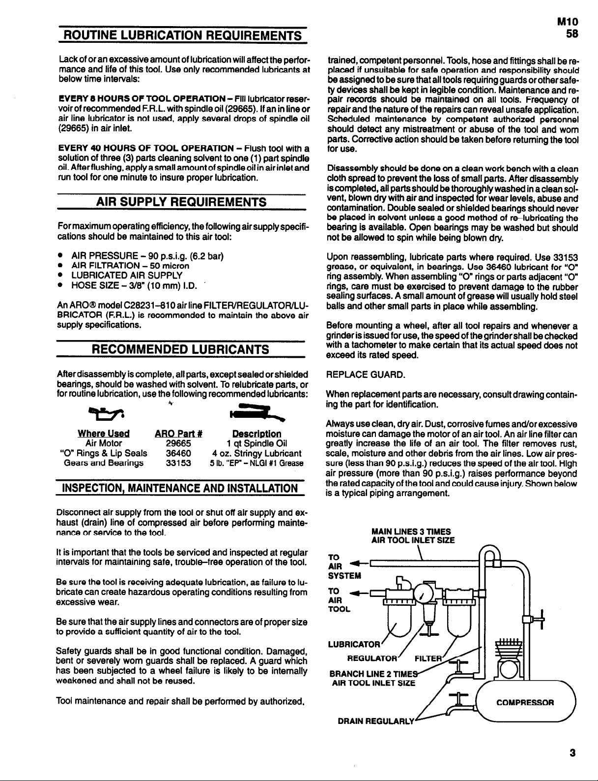
Always use clean, dry air. Dust, corrosive fumes and/or excessive
moisture can damage the motor of an air tool. An air line filter can
greatly increase the life of an air tool. The filter removes rust,
scale, moisture and other debris from the air lines. Low air pressure (less than 90 p.s.i.g.) reduces the speed of the air tool. High
air pressure (more than 90 p.s.i.g.) raises performance beyond
the rated capacity of the tool and could cause injury. Shown below
is a typical piping arrangement.
MAIN LINES 3 TlMES
AIR TOOL INLET SIZE
Tool maintenance and repair shall be performed by authorized,
COMPRESSOR
DRAIN REGULARLY
Page 4
MODEL IDENTIFICATION
with
Allow
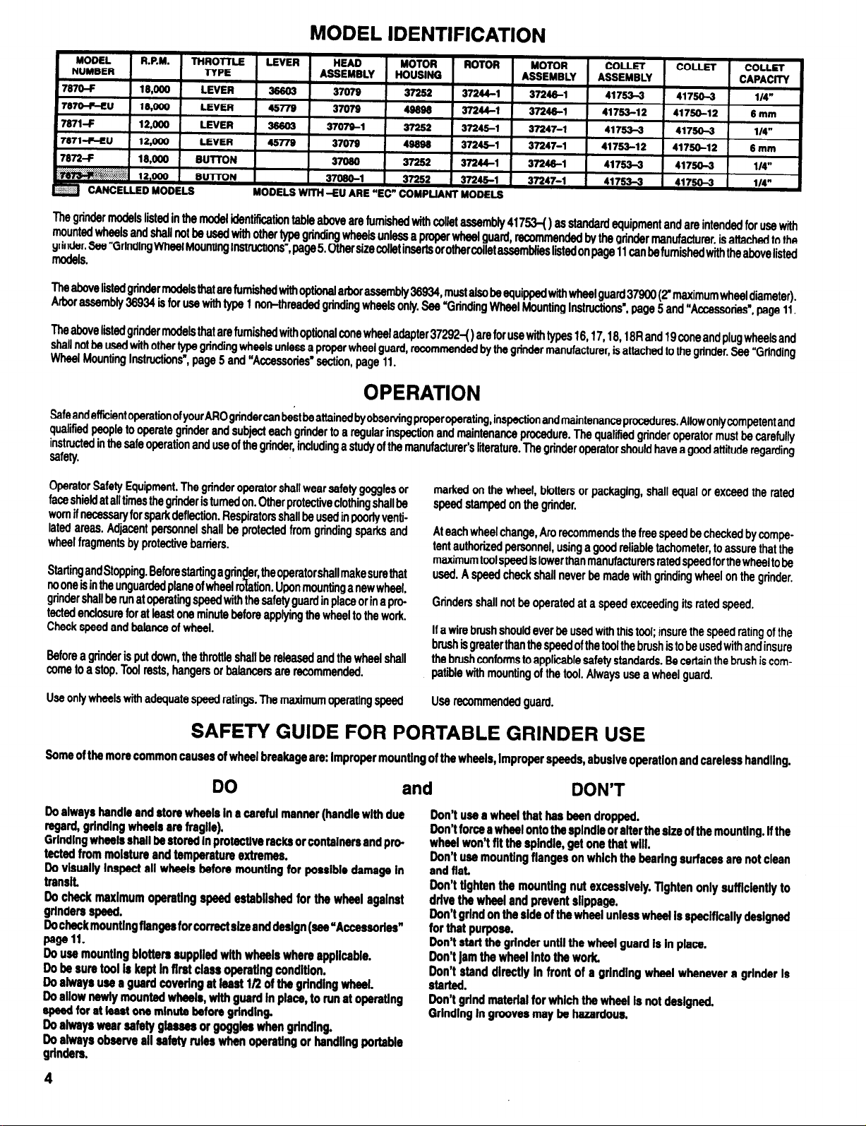
The grinder models listed in the model identification table above are furnished with collet assembly 41753-o as standard equipment and are intended for use with
mounted
Wheels
and shall not be used
grinder. See ”Grinding Wheel Mounting lnstructions”, page 5. Other size collet inserts or other collet assemblies listed on page 11 can furnished
models.
The above listed grinder models that are furnished with optional arbor assembly 36934, must also be equipped with wheel guard 37900 (2" maximum wheel diameter).
Arbor assembly 38934 is for use
The above listed grinder models that are furnished with optional cone wheel adapter 37292-( ) are for use with types 16,17,18,18R and 19 cone and plug wheels and
shall not be used with other type grinding wheels unless a proper wheel guard, recommended by the grinder manufacturer, is attached to the grinder. Bee “Grinding
Wheel Mounting Instructions”, page 5 and “Accessories’ section, page 11.
with
other type grinding wheels unless a proper wheel guard, recommended by the grinder manufacturer is attached to the
with
type 1 non-threaded grinding wheels only. See “Grinding Wheel Mounting Instructions”, page 5 and “Accessories”, page 11.
OPERATION
Safe and efficient operation of your ARO grinder can best be attained by observing proper operating, inspection and maintenance procedures.
qualified people to operate grinder and subject each grinder to a regular inspection and maintenance procedure. The qualified grinder operator must be carefully
instructed in the safe operation and use of the grinder, including a study of the manufacturer’s literature. The grinder operator should have a good attitude regarding
safety.
Operator Safety Equipment. The grinder operator shall wear safety goggles or
face shield at all times the grinder is turned on. Other protective clothing shall be
worn if necessary for spark deflection. Respirators shall be used in poorly ventilated areas. Adjacent personnel shall be protected from grinding sparks and
wheel fragments by protective barriers.
Starting and Stopping. Before starting a grinder, the operator shall make sure that
no one is in the unguarded plane of wheel rotation. Upon mounting a new wheel,
grinder shall be run at operating speed with the safety guard in place or in a protected enclosure for at least one minute before applying the wheel to the work.
Check speed and balance of wheel.
Before a grinder is put down, the throttle shall be released and the wheel shall
come to a stop. Tool rests, hangers or balancers are recommended.
Use only wheels with adequate speed ratings. The maximum operating speed Use recommended guard.
marked on the wheel, blotters or packaging, shall equal or exceed the rated
speed stamped on the grinder.
At each wheel change, Aro recommends the free speed be checked by competent authorized personnel, using a good reliable tachometer, to assure that the
maximum tool speed is lower than manufacturers rated speed for the wheel to be
used. A speed check shall never be made with grinding wheel on the grinder.
Grinders shall not be operated at a speed exceeding its rated speed.
If a wire brush should ever be used with this tool; insure the speed rating of the
brush is greater than the speed of the tool the brush is to be used with and insure
the brush conforms to applicable safety standards. Be certain the brush is compatible with mounting of the tool. Always use a wheel guard.
SAFETY GUIDE FOR PORTABLE GRINDER USE
Borne of the more common causes of wheel breakage are: Improper mounting of the wheels, Improper speeds, abusive operation and careless handling.
DO
Do always handle and store wheels In a careful manner (handle with due
regard, grlnding wheels are fragile).
Grlnding wheels shall be stored In protective racks or containers and protected from moisture and temperature extremes.
Do visually Inspect all wheels before mounting for possible damage In
transit.
Do
check
maximum operating speed established for the wheel against
grinders speed.
Do check mounting flanges for correct size and design (see “Accessories”
page 11.
Do use mounting blotters supplied with wheels where applicable.
Do be sure tool is kept in first class operating condition.
Do always use a guard covering at least 1/2 of the grinding wheel.
Do allow newly mounted wheels, with guard In place, to run at operating
speed for at least one minute before grlnding
Do always wear safety glasses or goggles when grinding.
Do always observe all safety rules when operating or handling portable
grinders.
and
Don’t use a wheel that has been dropped.
Don’t force a wheel onto the spindle or alter the size of the mounting. lf the
wheel won’t fit the spindle, get one that will.
Don’t use mounting flanges on which the bearing surfaces are not clean
and flat.
Don’t tighten the mounting nut excessively. Tighten only sufficiently to
drive the wheel and prevent slippage.
Don’t grind on the side of the wheel unless wheel is specifically designed
for that purpose.
Don’t start the grinder until the wheel guard Is In place.
Don’t jam the wheel Into the work,
Don’t stand directly In front of a grinding wheel whenever a grinder Is
Started.
Don’t grind material for which the wheel Is not designed.
Grinding In grooves may be hazardous.
DON’T
4
Page 5

GRINDING WHEEL MOUNTING INSTRUCTIONS
or
Disconnect air supply from grinder or shut off air supply and exhaust (drain) air
line of compressed air before mounting or removing any abrasive wheel or wire
brush, or otherwise performing maintenance or service to the tool.
Check grinder speed before mounting grinding wheel (or other type accessory)
with a reliable tachometer to make sure that the actual speed of the grinderdoes
not exceed its rated free speed.
Check operating speed of grinding wheel or wire brush to be used with the grinder. The maximum operating speed marked on the grinding wheel, blotters or
packaging, shall equal or exceed the rated free speed of the grinder. Also, the
type and size of the grinding wheel or wire brush shall be compatible with the
grinder size and type.
Check abrasive wheels prior to mounting for chips or cracks. Cracked
wheels shall not be used.
Care must be taken that a grinding wheel, or wire brush, of the correct speed rating is used. Rated wheel capacities for Aro grinders are maximum only. Regardless of the rated capacity and speed of any Aro grinder, abrasive wheels or wire
brushes shall never be operated at a speed greater than that recommended by
the wheel (or brush) manufacturer.
Dressing Abrasive Wheels. Upon mounting a grinding wheel, the tool should be
operated at gradually increasing speed and checked for good balance of the
wheel. If unbalance is observed, the wheel shall be dressed. If dressing fails to
establish acceptable balance, the wheel shall not be used.
MOUNTING INSTRUCTIONS FOR MOUNTED WHEELS
FOR USE WITH 33226-( ), 41753-( ) OR 44127-( ) COLLET ASSEMBLIES.
The collet shall be checked to assure it to be in good condition and properly affixed to the grinder spindle.
The mandrel shall be inserted to the full depth of the gripping jaws of the collet. At
least 1/2 the mandrel length shall be inserted into the collet.
The maximum safe operating speed for mounted wheels shall be determined by
the following: 1.) Shape and size of the mounted wheel, 2.) Sue of mandrel and
3.) Overhang of mandrel. In no case shall the maximum safe operating speed recommended by the wheel manufacturer be exceeded.
M10
WARNING: Work pressure, If excessive, can be the cause of trouble and a
source of danger, thru bending or fracture of the mandrel. Pressure between the wheel and the work should never be so heavy that springing of
the mandrel will result.
IMPORTANT NOTICE: Increasing the overhang of the mandrel will reduce the maximum wheel size that can be safely used with the speed of the tool (dimen-
sion “O”, figure 1). Also, the length and diameter of mandrel combined with the size and shape of the wheel are determining factors which must be consldered when selecting a mounted wheel that will be compatible with the rated free speed of the tool. lt Is recommended the “Tables of Maximum Operating
Speeds for Mounted Wheels” of the American National Standard publication B7.1-1978 previously mentioned or other reliable source, be consulted to
determine the safe operating speed of a particular size and shape of wheel combined with the size and overhang of mandrel.
MANDREL OVERHANG - DIMENSION “0”
FIGURE 1
MOUNTING INSTRUCTIONS FOR TYPE 1 GRINDING WHEELS
The driving flange shall be inspected to see that it is of the relieved type, that its
diameter is at least 1/3 the diameter of the wheel and that it is free of nicks, burrs
and sharp edges. A blotter, separate or attached to the wheel and at least the diameter of the driving flange, shall bear against the driving flange. The wheel shall
be placed on the spindle following the first blotter. The wheel shall not fit too snug-
ly nor too freely on the spindle. The normal diametral clearance between the
wheel and the spindle is approximately .007” (.17 mm) maximum. Abrasive
wheels which do not properly fit the spindle shall not be used. Separate reducing
bushings, unless supplied or recommended by the abrasive wheel manufacturer,
shall not be used to adapt larger hole abrasive wheels.
A second blotter, separate or attached to the wheel and at least the diameter of
the outside flange, shall follow the wheel on the spindle. An outer flange, the
same diameter as the driving flange, shall follow the second blotter. The outer
flange
shall have a relief and contact face identical to the driving flange, placed toward
the blotter.
A spindle end nut shall follow the outer flange. Hold spindle from rotating and
screw spindle end nuts firmly against the outer flange, but only tight enough to
insure sufficient friction on the blotter faces to drive the wheel. Excessive tightening can distort the flanges. The spindle shall project flush with or past the end of
the spindle end nut. To secure wheels thinner than the unthreaded length of the
spindle, a spacer shall be used between the flange and the spindle end nut. Such
a spacer shall be a precision part, with parallel faces running true to the spacer’s
center hole.
The safety guard shall be properly positioned and the mounting checked to assure secure positioning. The guard cover shall be closed and secured.
MOUNTING INSTRUCTIONS FOR TYPES 16,17,18,18R AND 19 CONE AND PLUG WHEELS
FOR USE WITH 37292-( ) WHEEL ADAPTER
The driving flange shall be inspected to see that it is of the flat, unrelieved type,
that its diameter is at least 1/3 the diameter of the wheel and that it is free of nicks,
burrs and sharp edges. The grinding wheel shall be tightened on the spindle by hand and shall bear firmly
The spindle and wheel threads shall be inspected to see that they are of the same
pitch and diameter and a blotter, separate or attached to the wheel and at least the
diameter of the driving flange, shall bear against the driving flange.
against the blotter and driving flange. If the wheel cannot be secured, the spindle
length shall be checked. If the spindle length is correct and the cone wheel still wilI
not fit firmly against the blotter and driving flange, the wheel shall not be used and
a proper fitting wheel shall be selected.
5
Page 6

DISASSEMBLY AND ASSEMBLY OF TOOLS
Disconnect air supply from tool or shut off air supply and exhaust
(drain) line of compressed air BEFORE performing maintenance
or service to tool.
Before starting to disassemble or assemble this tool (any part or
completely), be sure to read “Inspection, Maintenance and Installation” section,
To minimize the possibility of parts damage and for convenience,
the steps for disassembly or assembly listed on the following
pages are recommended.
The basic sections and instructions for removing them from the
tool are as follows:
MOTOR SECTION
Place head of tool in a suitable holding device, clamping on flats of
head. Remove collet nut and collet insert. Insert a 5/32” hex type
wrench thru collet body into end of rotor to secure rotor and unthread and remove collet body from rotor. Remove lock nut
(37253) and remove motor assembly from housing. See page B
for complete disassembly of motor.
HEAD SECTION
Throttle components can be serviced without removing head section from tool. See page 9 and 10 for complete disassembly,
Page 7

TYPICAL CROSS SECTION OF TOOL
Ml0
58
7
Page 8

DISASSEMBLY
MOTOR SECTION
Remove motor assembly from housing as outlined on page 6.
Remove retaining nut (33694). Grasp cylinder in one hand and
tap threaded end of rotor with a soft face hammer; motor will come
apart.
ASSEMBLY
NOTE: Pack bearings with ARO 33153 grease and coat i.d. of cylinder with ARO 29665 spindle oil upon assembly.
Assemble two bearings (39624) into end plate (37254) with the
sides of the bearings having the least clearance between the inner and outer races placed together (see figure below). NOTE:
Press on outer race of bearings. Assemble bearing (Y65-15) to
end plate (37291), pressing on outer race of bearing. Assemble
3/8-24
THREA
PIN Yl78-22~
TROLL
TROLL PIN
Yl76-
end plate (37291) to rotor, pressing on inner race of bearing. Assemble cylinder (36772) over rotor, aligning air inlets of cylinder
and end plate and roll pin (Y176-22) with hole in end plate. Assemble blades (41520) to rotor slots -straight side out. Assemble
spacer (37290) and end plate (37254) to rotor, pressing on inner
race of bearing. Assemble nut (33694) to end plate (37291) and
tighten to 9 - 12 ft Ibs.
Be sure rotor does not bind (if rotor binds, tap threaded end lightly
with a soft face hammer to loosen). Place head in a suitable holding device with the motor end upright and remove motor housing
from head. Place motor assembly on head, aligning roll pin
(Y176-22) with .125” diameter blind hole in head. Slip motor
housing over motor and tighten securely to head. Assemble lock
nut (37253) and Collet assembly to tool.
37245-l
-BLADE (6141520 /
EARING Y65-15
END PLATE
LASSEMEi..E
LEAST CLEARANCE BETWEEN IMUER AND
CUTER RACES TOGETqR
37254
SPACER 37290
BEARINGS WITH SIDES HAVING
I\_
-\
i!%i%tiEL (NON -EU MODELS)
49999 LABEL (-EU MODELS)
COLLET 41750-( ) (SEE TABLE, PAGE 4) A
/-
COLLET NUT 41751 A
A COLLET BODY 41752
318 -24 THREAD
OCKNUT 37253
:
\
kND PLATE 37291
-t-INCLUDED WITH CYLINDER 36772
$X TORQUE TO 9-12 FT LBS
I
A INCLUDED IN 41753-( ) COLLET ASSEMBLY (SEE TABLE, PAGE 4)
8
HOUSING (SEE TABLE, PAGE 4)
Page 9

DISASSEMBLY
HEAD SECTION
ASSEMBLY
Ml0
58
Remove nut (36776) and valve components can be removed
from head.
r
* RIVET 36992 -
“0” RING Y325-7
* PARTS NOT INCLUDED IN HEAD ASSEMBLY
-!-
Lubricate “0” ring (Y325-7) with ARO 38460 lubricant and assemble to valve stem. Assemble valve stem, spring (32656), regulator and seal (36781) to head and secure with nut (36776).
NOTE: Align notch (or hole) in side of regulator with air inlet of
head when assembling.
LEVER (SEE TABLE, PAGE 4) *
MUFFLER 49192 $
ADAPTER 32854
VALVE 36777
SEAL 36781 4
v NuT36776
LEVER HEAD ASSEMBLIES 37079 AND 37079-l
SPRING 32858
9
Page 10

HEAD SECTION
DISASSEMBLY
Remove nut (36778) and valve components can be removed
from head. To remove throttle button (36745), remove roll pin
(Y178-212).
ASSEMBLY
Lubricate “0” ring (Y326-7) with ARO 36460 lubricant and assemble to valve stem. Assemble valve stem, spring (32858), regulator and seal (36781) to head and secure with nut (36776).
NOTE: Align notch (or hole) in side of regulator with air inlet of
head when assembling.
ROLL PIN Y178-212
HEAD 37078
“0” RING Y325-7
BUTTON 36745
MUFFLER 49192 *
ADAPTER 32854
VALVE 35643
10
30131 WRENCH
Page 11

ACCESSORIES
41753-( ) 3-PIECE COLLET ASSEMBLY
33226-( ) 3-PIECE COLLET ASSEMBLY
M10
58
COLLETNUT-41751
COLLET BODY - 41752
3/8” - 24 THREAD
COLLET NUT DIA. - 3/4”
COLLET BODY DIA. - 21/32”
0VER ALL LENGTH - 2 1/4”
44127-( ) ERICKSON 3-PIECE COLLET ASSEMBLY
COLLET NUT - 33220
COLLET BODY - 32218
CUP RING - 33221
NOSE RING - 33222
318-24
THREAD
COLLET NUT DIA. - 15/16”
COLLET BODY MA. - 5/8”
OVER ALL LENGTH - 2”
3/8”- 24
THREAD
7
NOT
SHOWN, WING NUT (2) Y89-4
(INCLUDED WITH GUARD)
ADAPTER ASS'Y 36934
LEVER 45776
45779 LOCK-OFF LEVER ASSEMBLY
11
Page 12

TROUBLE SHOOTING
LISTED BELOW ARE SOME OF THE MOST COMMON CAUSES FOR THE GRINDER TO MALFUNCTION. MALFUNCTIONS BEYOND THE SCOPE OF THIS MANUAL
SHOULD BE BROUGHT TO THE ATTENTION OF YOUR ARO REPRESENTATIVE OR RETURN
THE
TOOL TO THE FACTORY FOR REPAIR.
CONDlTlON
LOW SPEED AND
POWER OR GRINDER WILL NOT RUN.
THROTTLE VALVE
HARD TO OPERATE.
TOOL WILL NOT
SHUT OFF.
POSSIBLE CAUSE
1. INADEQUATE AIR SUPPLY.
2. AIR REGULATOR (38775) IMPROPERLY ADJUSTED.
3. AIR INLET OR EXHAUST SCREEN
PLUGGED.
4. OBSTRUCTION IN THROTTLE VALVE
OR VALVE NOT OPENING.
5. MOTOR NOT BEING PROPERLY LU-
BRICATED.
8. ROTOR BLADE IS MISSING, INCOR-
RECTLY INSTALLED, BADLY WORN
OR BEARING FAILURE.
1. DAMAGED VALVE PIN OR “0” RING.
I
DIMENSIONAL DATA
CORRECTlVE ACTION
1. CHECK AIR SUPPLY FOR CORRECT REGULATOR ADJUSTMENT (90 P.S.I.G. MAX. WHEN TOOL IS OPERATlNG).
2. CHECK REGULATOR ADJUSTMENT TO BE SURE OF MAXIMUM
AIR FLOW.
3. INSPECT, WASH CLEAN.
4. D&ASSEMBLE THROTTLE, CLEAN, INSPECT FOR OBSTRUCTIONS OR DAMAGED PARTS.
5. APPLY 2 OR 4 DROPS OF SPINDLE OIL IN AIR INLET. RUN TOOL
TO ALLOW OIL TO ENTER MOTOR - BE CERTAIN OILER IS
FULL OF OIL
8. DISASSEMBLE MOTOR, CLEAN AND INSPECT FOR PROPER
INSTALLATION, REPLACE BLADES AND/OR BEARINGS IF NEC-
ESSARY.
1. DISASSEMBLE VALVE COMPONENTS, INSPECT, REPLACE IF
NECESSARY.
1. DISASSEMBLE VALVE COMPONENTS, INSPECT. REPLACE 1. DAMAGED VALVE COMPONENTS.
PARTS IF NECESSARY.
I
L
1-7/8”
(48 mm)
AIR
1/4” N.P.T.F. AIR INLET
1/4” N.P.T.F. AIR INLET
PN 49999-064
 Loading...