

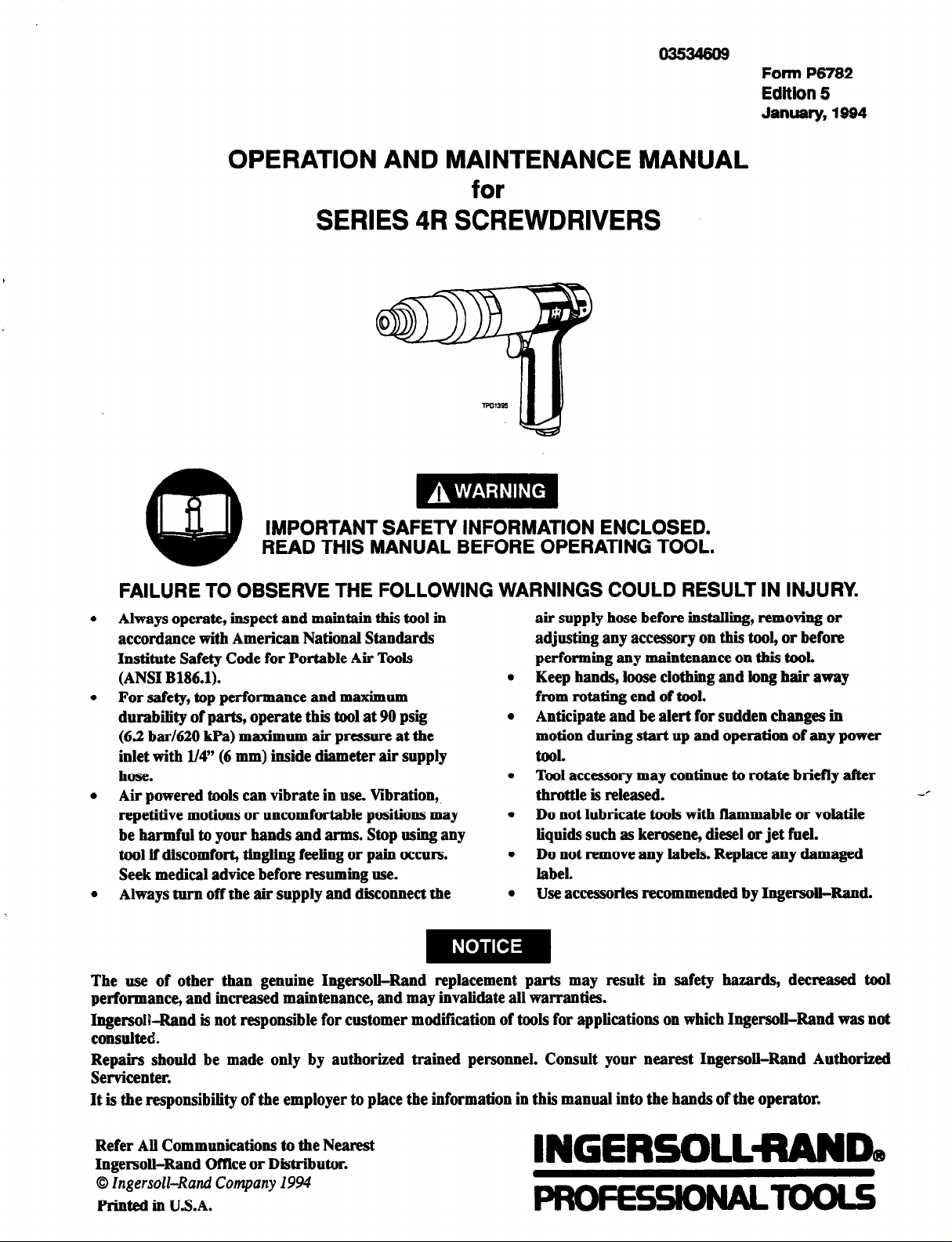
Ingersoll-Rand 4RSERIES Operation And Maintenance Manual
03534809
OPERATION AND MAINTENANCE MANUAL
for
SERIES 4R SCREWDRIVERS
Form P6782
Edition 5
January, 1994
IMPORTANT SAFETY INFORMATION ENCLOSED.
READ THIS MANUAL BEFORE OPERATING TOOL.
FAILURE TO OBSERVE THE FOLLOWING WARNINGS COULD RESULT IN INJURY.
l
Always operate, inspect and maintain this tool in
accordance with American National Standards
Institute Safety Code for Portable Air Tools
(ANSI B186.1).
l
For safety, top performance and maximum
durability of parts, operate this tool at 90 psig
(6.2 bar/620 kPa) maximum air pressure at the
inlet with 1/4” (6 mm) inside diameter air supply
hose.
l
Air powered tools can vibrate in use. Vibration,
repetitive motions or uncomfortable positions may
be harmful to your hands and arms. Stop using any
tool if discomfort, tingling feeling or pain occurs.
Seek medical advice before resuming use.
l
Always turn off the air supply and disconnect the
The use of other than genuine Ingersoll-Rand replacement parts may result in safety hazards, decreased tool
performance, and increased maintenance, and may invalidate all warranties.
Ingersoll-Rand is not responsible for customer modification of tools for applications on which Ingersoll-Rand was not
consulted.
Repairs should be made only by authorized trained personnel. Consult your nearest Ingersoll-Rand Authorized
Servicenter.
It is the responsibility of the employer to place the information in this manual into the hands of the operator.
air supply hose before installing, removing or
adjusting any accessory on this tool, or before
performing any maintenance on this tool.
l
Keep hands, loose clothing and long hair away
from rotating end of tool.
l
Anticipate and be alert for sudden changes in
motion during start up and operation of any power
tool.
l
Tool accessory may continue to rotate briefly after
throttle is released.
l
Do not lubricate tools with flammable or volatile
liquids such as kerosene, diesel or jet fuel.
l
Do not remove any labels. Replace any damaged
label.
l
Use accessories recommended by Ingersoll-Rand.
Refer All Communications to the Nearest
Ingersoll-Rand Office or Distributor.
© Ingersoll-Rand Company 1994
Printed in U.S.A.

WARNING LABEL IDENTIFICATION
FAILURE TO OBSERVE THE FOLLOWING WARNINGS COULD RESULT IN INJURY.
A WARNING
Always wear eye protection
when operating or performing maintenance on this
tool.
e, WARNING
Always turn off the air
supply and disconnect the
air supply hose before
installing, removing or
adjusting any accessory on
this tool, or before performing any maintenance on this
tool.
A WARNING
Do not carry the tool by
the hose.
I
A WARNING
Always wear hearing
protection when operating
this tool.
A WARNING
Air powered tools can
vibrate in use. Vibration,
repetitive motions or uncomfortable positions may be
harmful to your hands and
arms. Stop using any tool if
discomfort, tingling feeling
or pain occurs. Seek medical advice before resuming
use.
pI WARNING
I
Do not use damaged, frayed
or deteriorated air hoses
and fittings.
A WARNING
Keep body stance balanced
and firm. Do not overreach
when operating this tool.
A WARNING
Operate at 90 psig
(6.2 bar/620 kPa)
Maximum air pressure.
2
PLACING TOOL IN SERVICE
LUBRICATION
Ingersoll-Rand No. 10 Ingersoll-Rand No. 28
Ingersoll-Rand No. 67
Always use an air line lubricator with these tools.
We recommend the following Filter-Lubricator-Regulator
Unit:
For USA - No. C05-02-G00
For International -No. C01-C2-T29
Before starting the tool and after each eight hours of
operation, unless an air
few drops of Ingersoll-Rand No. 10 Gil into the air inlet.
The cavity around outside of Rear Rotor Bearing (42) in
Motor Housing (1) should be filled 50 to 75 percent
capacity with Ingersoll-Rand No. 28 Grease.
Gearing
For models
with L gearing, inject approximately 6 to
8 cc of Ingersoll-Rand No. 28 Grease into the Grease
Fitting (5 1) in the Gear Case (50) after each 50 000 cycles
or 100 hours of operation, whichever comes first.
For models with M, N or P gearing,
approximately 10 to 12 cc of Ingersoll-Rand No. 28
Grease into the Grease Fitting (5 1) in the Gear Case (50)
after each 50 000 cycles or 100 hours of operation,
whichever comes first.
Clutch
Lubricate the 4C15, 4C17 or 4Sl Adjustable Clutch with 6
to 8 cc of Ingersoll-Rand No. 67 Grease after each 50 000
cycles or each 100 hours of operation, whichever occurs
first. Lubricate the Clutches as follows:
line lubricator is used, inject a
inject
clockwise
for the 4C15 and
counterclockwise
for the
4S1 until there is no compression on the Clutch
spring (112 or 261).
For 4C17,
insert the Clutch Adjusting Key into the
hole in the Clutch Adjusting Nut and, while holding
the Nut against rotation and pushing against the Bit
Holder to engage the clutch jaws, rotate the Bit
Holder counterclockwise until them is no compression
on the Clutch Spring (209).
Using a wrench on the flats of the Gear Case and an
4.
adjustable spanner wrench in the slot of the Clutch
Housing, unscrew the Clutch Housing from the Gear
Case.
This is a left-hand thread; turn clockwise to
remove.
For 4C15, using
5.
snap ring pliers, remove the Sleeve
Spring Retainer (119) from the Bit Holder. Slide the
Retaining Sleeve Spring (118) and Bit Retaining
Sleeve (117) from the Bit Holder and remove the Bit
Retaining Ball (116).
Withdraw the assembled clutch from the Clutch
6.
Housing and lubricate all bearing surfaces, bearings
and balls with the recommended grease.
Do not get your fingers between the clutch
components.
To reassemble the Clutch, perform steps 3 through 6
7.
in Changing the Clutch Spring.
CLUTCH ADJUSTMENT
Turn off the air supply and disconnect the air supply
hose at the tool before performing any maintenance.
1. Rotate the Adjusting Hole Cover (103,219 or 252) to
expose the slot in the Clutch Housing (101,201 or
250).
2.
For 4C15 or 4S1,
insert a l/4” Allen Wrench into the
Bit Holder (106 or 270) and rotate the Bit Holder until
the hole in the Clutch Adjusting Nut (113 or 256) is
aligned with the slot in the Clutch Housing.
For 4C17,
insert a l/4” Allen Wrench into the Bit
Holder (217) and, while pushing against the Bit
Holder to engage the clutch jaws, rotate the Bit
Holder until the hole in the Clutch Adjusting Nut
(214) is aligned with the slot in the Clutch Housing.
3.
For 4C15 or 4S1,
insert the Clutch Adjusting Key
into the hole in the Clutch Adjusting Nut and, while
holding the Nut against rotation, rotate the Bit Holder
The 4C15, 4C17 and 4Sl clutches can be externally
adjusted within a certain range to ratchet when a
predetermined torque has been delivered. To adjust the
clutch, proceed as follows:
1.
Turn off the air supply and disconnect the air
supply hose at the tool before proceeding.
2. Rotate the Adjusting Hole Cover (103,219 or 252) to
expose the slot in the Clutch Housing (101,201 or
250).
3.
For 4C15 or 4S1, insert
a l/4”
Allen
Wrench into
the Bit Holder (106 or 270) and rotate the Bit Holder
until the hole in the Clutch Adjusting Nut (113 or
256)
is aligned with the slot in the Clutch Housing.
For 4C17,
insert a l/4” Allen Wrench into the Bit
Holder (217) and, while pushing against the Bit
Holder to engage the clutch jaws, rotate the Bit
Holder until the hole in the Clutch Adjusting Nut
(214) is aligned with the slot in the Clutch Housing.
PLACING TOOL IN SERVICE
4.
For 4C15 or 4S1,
into the hole in the Clutch Adjusting Nut and, while
holding the Nut against rotation, rotate the Bit Holder
to adjust the torque output.
For 4C17,
hole in the Clutch Adjusting Nut and, while holding
the Nut against rotation and pushing against the Bit
Holder to engage the clutch jaws, rotate the Bit
Holder to adjust the torque output.
5. Rotating the Bit Holder clockwise increases the
compression on the Clutch Spring (112,209 or 261)
and raises the torque at which the clutch will ratchet.
The most satisfactory adjustment is usually
obtained by use of the tool on the actual
application, and increasing or decreasing the
delivered torque until the desired setting is
reached. In any event, it is recommended that the
final adjustment be made by gradual progression.
These clutches, when equipped with a Heavy
Spring, can he set beyond the torque capacity of
the tool, in which case the tool will stall before the
clutch ratchets. Do not adjust the clutch beyond
the torque capacity of the tool.
- CHANGING THE CLUTCH SPRING -
Additional Clutch Springs are available for these clutches
which allow the tools to be used when the desired torque
does not fall within the torque range of the furnished
Spring. To change a Clutch Spring (112,209 or 261)
proceed as follows:
1. Withdraw the assembled clutch from the Clutch
Housing (101,201 or 250) after performing steps 1
through 6 as described in the section
Lubrication.
2. To change the Clutch Spring in the 4C15 Clutch,
proceed as follows:
a. Grasp the spline of the Clutch Shaft Support
(120) in leather-covered or copper-covered vise
jaws with the Bit Holder (106) upward.
b. Using snap ring piers, remove the Bit Holder
stop (115).
c. Using a wrench and keeping pressure against the
Spring Seat (110) to prevent the Clutch Balls
(108) from falling out of position, unscrew and
remove the Clutch Adjusting Nut (113).
insert the Clutch Adjusting Key
insert the Clutch Adjusting Key into the
Clutch
This is a left-hand thread; turn clockwise to
remove.
d. Lift off the Adjusting Nut Lock (114) and the
Clutch Spring.
e. Install the new Clutch Spring and replace the
Adjusting Nut Lock.
f. Thread the Clutch Adjusting Nut onto the Bit
Holder and replace the Bit Holder Stop.
g. Remove the assembled clutch from the vise.
3. To change the Clutch Spring in the 4C17
Clutch, proceed as follows:
Carefully grasp the Front Clutch Jaw (204) in
a.
leather-covered or copper-covered vise jaws
with the Clutch Adjusting Nut (214) upward.
Using a wrench on the flats of the Clutch
b.
Adjusting Nut (214), loosen and remove the Nut.
With the assembly in the vise and while applying
C.
slight downward pressure to the Clutch Ball Seat
(208), remove the Adjusting Nut Lock (213),
Spring Seat Bearing (212), Clutch Spring Seat
(211) and the Clutch Spring from the Clutch
Driver (203).
Thoroughly grease the Bearing and Adjusting Nut
d.
Lock, and in the order named, slide the following
over the Clutch Driver: the new Clutch Spring,
the Clutch Spring Seat, the Spring Seat Bearing
and the Adjusting Nut Lock, indented side
trailing.
e.
Start the Clutch Adjusting Nut, detent side first,
onto the Clutch Driver and run it finger tight
against the compression of the Spring. With a
wrench, tighten the Nut an additional one or two
turns.
f.
Remove the assembled clutch from the vise.
4. To change the Clutch Spring in the 4Sl Clutch,
proceed as follows:
a Grasp a l/4” Allen Wrench in vise jaws with a
section of the hex pointing upward. Position the
Bit Holder (270) on the Allen Wrench so that the
splined end of the Clutch Driver (253) is upward
b. Remove the Clutch Return Spring (254) and
Return Spring Collar (255) from the Clutch
Driver.
c. Using snap ring pliers, remove the Spring Seat
Stop (260) from the threaded section of the
Clutch Driver.
d. Using a wrench, unscrew and remove the Clutch
Adjusting Nut (256).
PLACING TOOL IN SERVICE
e.
Lift off the Adjusting Nut Lock (257), the Thrust
Bearing (258), the Clutch Spring Seat (259) and
the Clutch Spring from the Clutch Driver.
f.
Thoroughly grease the Bearing and Adjusting Nut
Lock, and in the order named, slide the following
over the Clutch Driver: the new Clutch Spring,
the Clutch Spring Seat, the Thrust Bearing and
the Adjusting Nut Lock, indented side trailing.
Start the Clutch Adjusting Nut, detent side first,
onto the Clutch Driver and run it finger tight
against the compression of the Spring. With a
wrench, tighten the Nut an additional one or two
turns.
h.
Using snap ring pliers, install the Spring Seat
Stop on the Clutch Driver.
i.
Place the Return Spring Collar, concave end
trailing, and the Clutch Return Spring on the
splined end of the Clutch Driver.
Remove the assembled clutch from the Allen
j.
Wrench and the wrench from the vise.
5.
Insert the assembled clutch, Bit Holder end first, into
the Clutch Housing.
6.
For 4C15, insert the Bit Retaining Ball into the hole
in the Bit Driver. Install the Bit Retaining Sleeve on
the hub of the Bit Holder against the Bit Retaining
Sleeve Stop (123). Install the Retaining Sleeve
Spring on the Bit Holder and inside the Sleeve. Using
snap ring pliers and compressing the Spring, install
the Sleeve Spring Retainer in the external groove near
the output end of the Bit Holder.
7.
Thread the assembled Clutch onto the Gear Case.
This is a left-hand thread; turn clockwise to
remove.
lighten the Clutch Housing between 2 to 5 ft-lb
(3 to 7 Nm) torque.
8. Adjust the Clutch as directed in the section Clutch
Adjustment.
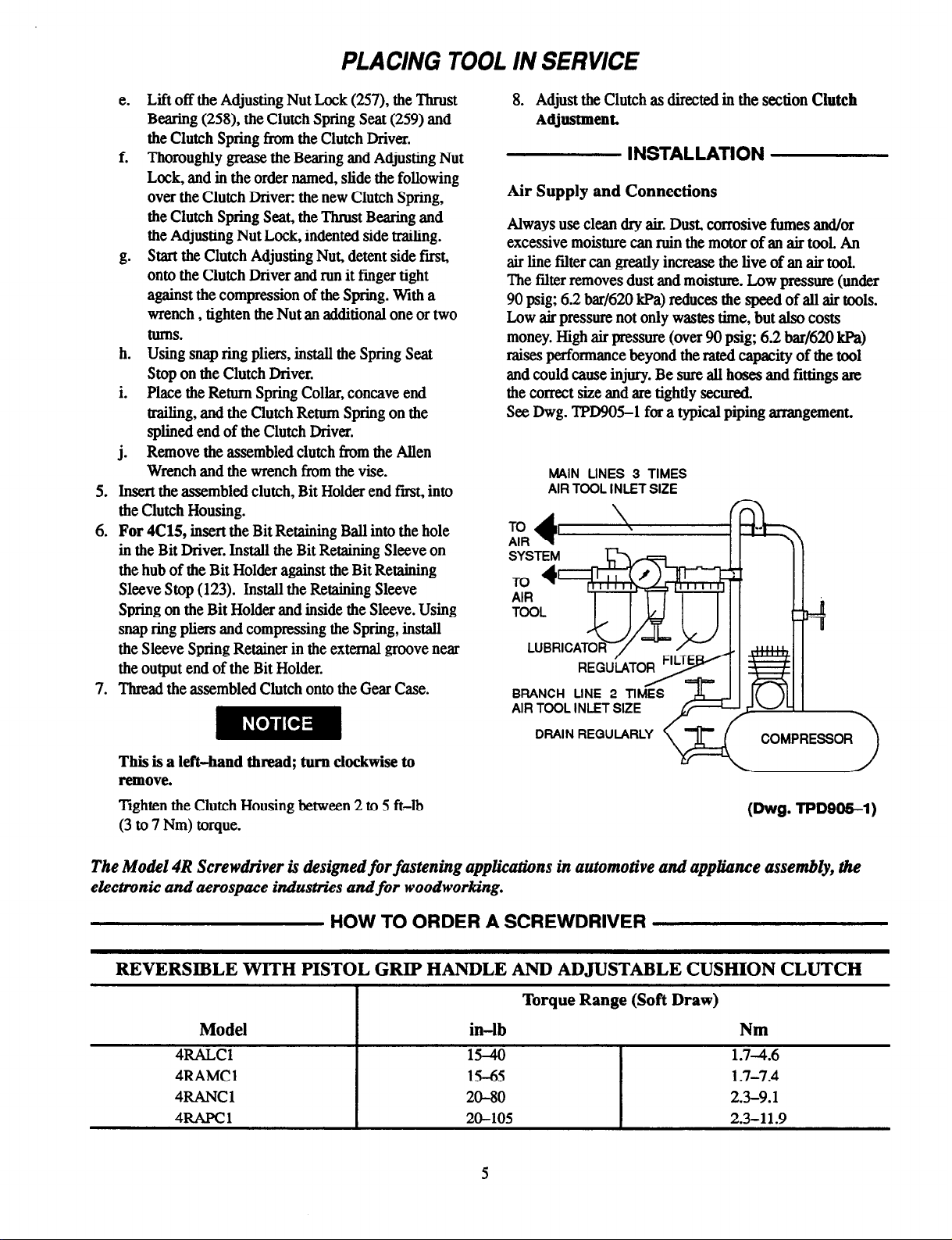
INSTALLATION
Air Supply and Connections
Always use clean dry air. Dust, corrosive fumes and/or
excessive moisture can ruin the motor of an air tool. An
air line filter can greatly increase the live of an air tool.
The filter removes dust and moisture. Low pressure (under
90 psig; 6.2 bar/620 kPa) reduces the speed of all air tools.
Low air pressure not only wastes time, but also costs
money. High air pressure (over 90 psig; 6.2 bar/620 kPa)
raises performance beyond the rated capacity of the tool
and could cause injury. Be sure all hoses and fittings ate
the correct size and are tightly secured.
See Dwg. TPD905-1 for a typical piping arrangement.
MAIN LINES 3 TIMES
AIR TOOL INLET SIZE
TO
AIR
AIR TOOL INLET SIZE
DRAIN REGULARLY
COMPRESSOR
(Dwg. TPD905-1)
The Model 4R Screwdriver is &signed
electronic and aerospace industries and
for
fastening applications in automotive and appliance assembly, the
for
woodworking.
HOW TO ORDER A SCREWDRIVER
REVERSIBLE WITH PISTOL GRIP HANDLE AND ADJUSTABLE CUSHION CLUTCH
Torque Range (Soft Draw)
Model
.-----
4RAMCl
4RANCl
4RAPCl
I
in-lb
-- .-
15-65
20-80
20-105
5
Nm
-.. ..-
l-7-7.4
2.3-9.1
2.3-11.9
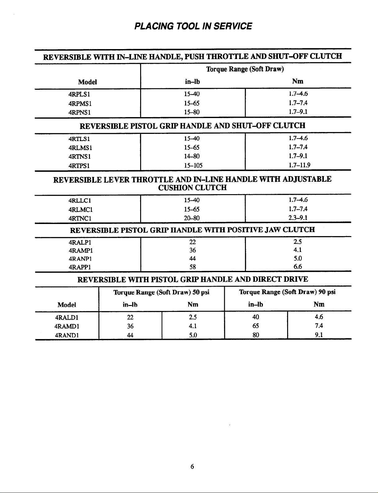
PLACING TOOL IN SERVICE
REVERSIBLE WITH IN-LINE HANDLE, PUSH THROTTLE AND SHUT-OFF CLUTCH
Torque Range (Soft Draw)
Model
4RPLS1
4RPMS1
4RPNS1
in-lb Nm
15-40
15-65
15-80
1.7-4.6
1.7-7.4
1.7-9.1
REVERSIBLE PISTOL GRIP HANDLE AND SHUT-OFF CLUTCH
4RTLS1
4RLMSl
4RTNS1
4RTPSl
15-40
15-65
14-80
15-105
1.74.6
1.7-7.4
1.7-9.1
1.7-11.9
REVERSIBLE LEVER THROTTLE AND IN-LINE HANDLE WITH ADJUSTABLE
CUSHION CLUTCH
4RLLCl
4RLMCl
4RTNCl
15-40
15-65
20-80
1.74.6
1.7-7.4
2.3-9.1
REVERSIBLE PISTOL GRIP HANDLE WITH POSITIVE JAW CLUTCH
4RALPl
4FAMPl
4FANPl
4RAPPl
I
22
36
44
58
2.5
4.1
5.0
I
6.6
REVERSIBLE WITH PISTOL GRIP HANDLE AND DIRECT DRIVE
Model
4RALDl
4RAMDl
4RANDl
Torque Range (Soft Draw) 50 psi Torque Range (Soft Draw) 90 psi
in-lb
22
36
44
Nm
2.5
4.1
5.0
in-lb
40
65
80
Nm
4.6
7.4
9.1
MAINTENANCE SECTION
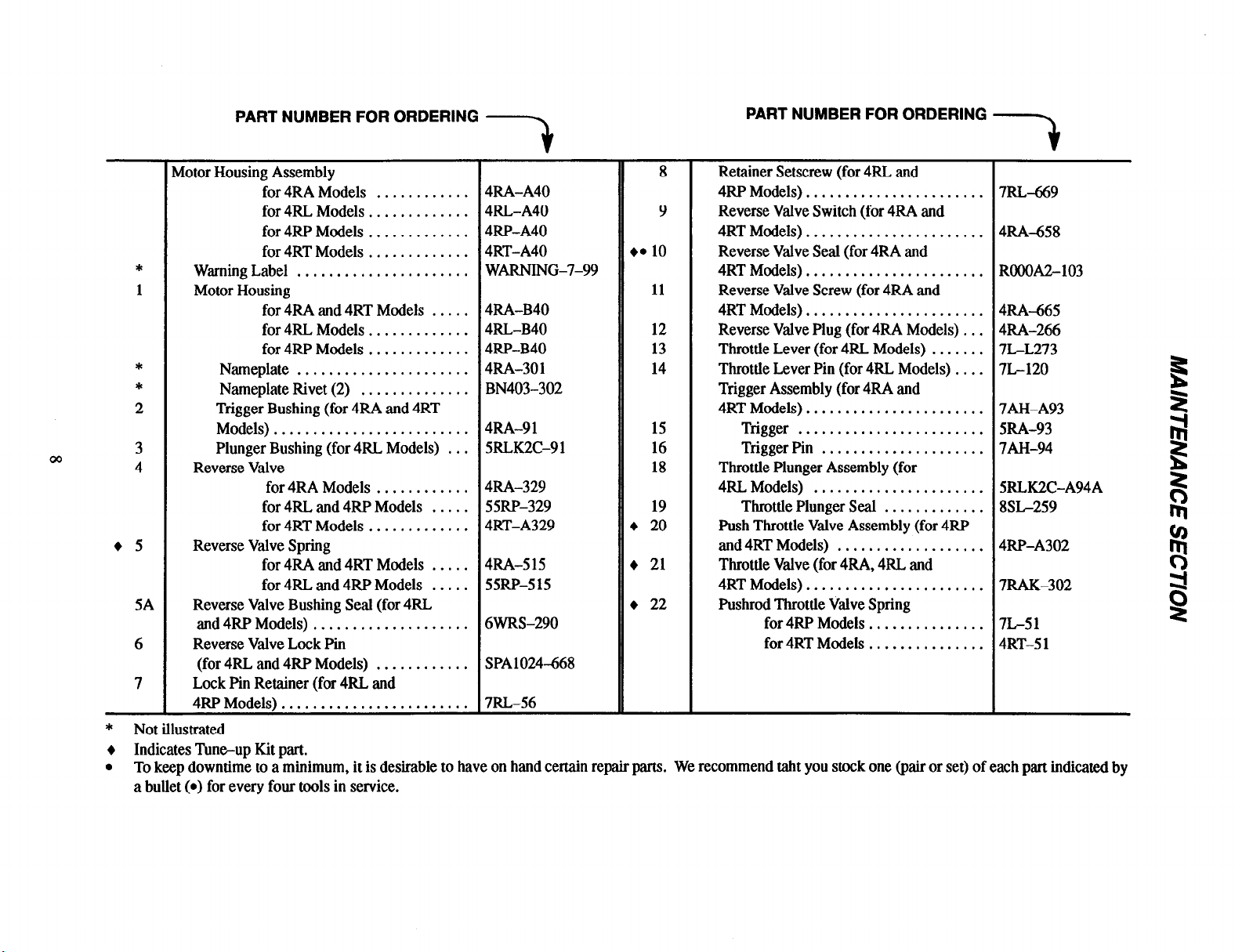
PART NUMBER FOR ORDERING
PART NUMBER FOR ORDERING --
t
Motor Housing Assembly
for 4RA Models ............
for 4RL Models .............
for 4RP Models .............
for 4RT Models .............
*
1
Warning Label ......................
Motor Housing
for 4RA and 4RT Models .....
for 4RL Models .............
for 4RP Models .............
*
*
2
Nameplate ......................
Nameplate Rivet (2) ..............
Trigger Bushing (for 4RA and 4RT
Models) .........................
3
4
Plunger Bushing (for 4RL Models) ...
Reverse Valve
for 4RA Models ............
for 4RL and 4RP Models .....
for 4RT Models .............
l
5
Reverse Valve Spring
for 4RA and 4RT Models .....
for 4RL and 4RP Models .....
5A
Reverse Valve Bushing Seal (for 4RL
and 4RP Models) ....................
6
7
Reverse Valve Lock Pin
(for 4RL and 4RP Models)
............
Lock Pin Retainer (for 4RL and
4RP Models) . . . . . . . . . . . . . . . . . . . . . . . .
4RA-A40
4RL-A40
4RP-A40
4RT-A40
WARNING-7-99
4RA-B40
4RL-B40
4RP-B40
4RA-301
BN403-302
4RA-91
5RLK2C-91
4RA-329
55RP-329
4RT-A329
4RA-515
55RP-515
6WRS-290
SPA1024668
7RL-56
8
9
l
a 10
11
12
13
14
15
16
18
19
+ 20
+ 21
l
22
Retainer Setscrew (for 4RL and
4RP Models) .......................
Reverse Valve Switch (for 4RA and
4RT Models) .......................
Reverse Valve Seal (for 4RA and
4RT Models) .......................
Reverse Valve Screw (for 4RA and
4RT Models) .......................
Reverse Valve Plug (for 4RA Models) ...
Throttle Lever (for 4RL Models) .......
Throttle Lever Pin (for 4RL Models) ....
Trigger Assembly (for 4RA and
4RT Models) .......................
Trigger ........................
Trigger Pin .....................
Throttle Plunger Assembly (for
4RL Models) ......................
Throttle Plunger Seal .............
Push Throttle Valve Assembly (for 4RP
and 4RT Models) ...................
Throttle Valve (for 4RA, 4RL and
4RT Models) .......................
Pushrod Throttle Valve Spring
for 4RP Models ...............
for 4RT Models ...............
7RL-669
4RA-658
ROOOA2-103
4RA-665
4RA-266
7L-L273
7L-120
7AH-A93
5RA-93
7AH-94
5RLK2C-A94A
8SL-259
4RP-A302
7RAK-302
7L-51
4RT-51
t
* Not illustrated
Indicates Tune-up Kit part.
l
To keep downtime to a minimum, it is desirable to have on hand certain repair parts. We recommend taht you stock one (pair or set) of each part indicated by
a bullet (•) for every four tools in service.
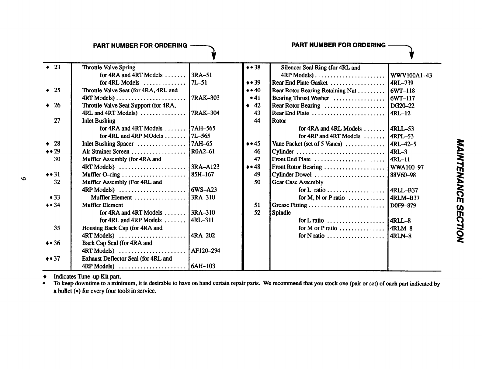
PART NUMBER FOR ORDERING
Silencer Seal Ring (for 4RL and
4RP Models)
.......................
..................
.........
.................
....................
........................
for 4RA and 4RL Models
for 4RP and 4RT Models
.......
.......
.............
.............................
....................
.......................
for L ratio
for M, N or P ratio
...................
............
.........................
for L ratio
for M or P ratio
for N ratio
...................
...............
...................
WWVlOOA1-43
4RL-739
6WT-118
6WT-117
DG20-22
4RL-12
4RLL-53
4RPL-53
4RL-42-5
4RL-3
4RL-11
WWAlOO-97
88V60-98
4RLL-B37
4RLM-B37
DOF9-879
4RLL-8
4RLM-8
4RLN-8
l
l
*34
23
25
26
27
28
29
30
31
32
33
35
36
37
PART NUMBER FOR ORDERING
Throttle Valve Spring
for 4RA and 4RT Models .......
for 4RL Models ..............
Throttle Valve Seat (for 4RA, 4RL and
4RT Models) .......................
Throttle Valve Seat Support (for 4RA,
4RL and 4RT Models) ...............
Inlet Bushing
for 4RA and 4RT Models .......
for 4RL and 4RP Models.. .....
Inlet Bushing Spacer
................
Air Strainer Screen ..................
Muffler Assembly (for 4RA and
4RT Models) ......................
Muffler O-ring .....................
Muffler Assembly (For 4RL and
4RP Models)
......................
Muffler Element .................
Muffler Element
for 4RA and 4RT Models .......
for 4RL and 4RP Models .......
Housing Back Cap (for 4RA and
4RT Models)
......................
Back Cap Seal (for 4RA and
4RT Models)
......................
Exhaust Deflector SeaI (for 4RL and
4RP Models) ......................
t
3RA-51
7L-51
7RAK-303
7RAK-304
7AH-565
7L-565
7AH-65
ROA2-61
3RA-A123
85H-167
6WS-A23
3RA-310
3RA-310
4RL-311
4RA-202
AF120-294
6AH-103
38
em 39
•41
42
43
44
45
46
47
48
49
50
51
52
Rear End Plate Gasket
Rear Rotor Bearing Retaining Nut
Bearing Thrust Washer
Rear Rotor Bearing
Rear End Plate
Rotor
Vane Packet (set of 5 Vanes)
Cylinder
Front End Plate .......................
Front Rotor Bearing
Cylinder Dowel
Gear Case Assembly
Grease Fitting
Spindle
Indicates Tuneup Kit part.
l
To keep downtime to a minimum, it is desirable to have on hand certain repair parts. We recommend that you stock one (pair or set) of each part indicated by
a bullet (•) for every four tools in service.
 Loading...