

Ingersoll-Rand 4MUC4518A10N0A, 4MUC4524A10NA, 4MUC4548A10N0A, 4MUC4530A10N0A, 4MUC4536A10N0A Installation Operation & Maintenance
...
Installation, Operation,
and Maintenance
C-Series
Cassette Indoor Units
Models: 4MUC4518A10N0A, 4MUC4524A10NA, 4MUC4530A10N0A, 4MUC4536A10N0A, 4MUC4542A10N0A,
4MUC4548A10N0A
Only qualified personnel should install and service the equipment. The installation, starting up, and
servicing of heating, ventilating, and air-conditioning equipment can be hazardous and requires specific
knowledge and training. Improperly installed, adjusted or altered equipment by an unqualified person could
result in death or serious injury. When working on the equipment, observe all precautions in the literature
and on the tags, stickers, and labels that are attached to the equipment.
May 2015
SAFETY WARNING
MS-SVX039A-EN
DB68-05139A(1)
Introduction
Read this manual thoroughly before operating or servicing
this unit.
Warnings, Cautions, and Notices
Safety advisories appear throughout this manual as
required. Your personal safety and the proper operation of
this machine depend upon the strict observance of these
precautions.
The three types of advisories are defined as follows:
WARNI NG
Proper Field Wiring and Grounding
Required!
Failure to follow code could result in death or serious
injury. All field wiring MUST be performed by qualified
personnel. Improperly installed and grounded field
wiring poses FIRE and ELECTROCUTION hazards. To
avoid these hazards, you MUST follow requirements for
field wiring installation and grounding as described in
NEC and your local/state electrical codes.
WARNING
CAUTIONs
NOTICE
Indicates a potentially hazardous
situation which, if not avoided, could
result in death or serious injury.
Indicates a potentially hazardous
situation which, if not avoided, could
result in minor or moderate injury. It
could also be used to alert against
unsafe practices.
Indicates a situation that could result in
equipment or property-damage only.
Important Environmental Concerns
Scientific research has shown that certain man-made
chemicals can affect the earth’s naturally occurring
stratospheric ozone layer when released to the
atmosphere. In particular, several of the identified
chemicals that may affect the ozone layer are refrigerants
that contain Chlorine, Fluorine and Carbon (CFCs) and
those containing Hydrogen, Chlorine, Fluorine and
Carbon (HCFCs). Not all refrigerants containing these
compounds have the same potential impact to the
environment. Trane advocates the responsible handling of
all refrigerants-including industry replacements for CFCs
such as HCFCs and HFCs.
Important Responsible Refrigerant
Practices
Trane believes that responsible refrigerant practices are
important to the environment, our customers, and the air
conditioning industry. All technicians who handle
refrigerants must be certified. The Federal Clean Air Act
(Section 608) sets forth the requirements for handling,
reclaiming, recovering and recycling of certain
refrigerants and the equipment that is used in these
service procedures. In addition, some states or
municipalities may have additional requirements that
must also be adhered to for responsible management of
refrigerants. Know the applicable laws and follow them.
WARNI NG
Personal Protective Equipment (PPE)
Required!
Failure to wear proper PPE for the job being undertaken
could result in death or serious injury. Technicians, in
order to protect themselves from potential electrical,
mechanical, and chemical hazards, MUST follow
precautions in this manual and on the tags, stickers,
and labels, as well as the instructions below:
• Before installing/servicing this unit, technicians
MUST put on all PPE recommended for the work
being undertaken. ALWAYS refer to appropriate
MSDS sheets and OSHA guidelines for proper PPE.
• When working with or around hazardous chemicals,
ALWAYS refer to the appropriate MSDS sheets and
OSHA guidelines for information on allowable
personal exposure levels, proper respiratory
protection, and handling recommendations.
• If there is a risk of arc or flash, technicians MUST put
on all PPE in accordance with NFPA 70E or other
country-specific requirements for arc flash
protection, PRIOR to servicing the unit.
Copyright
This document and the information in it are the property of
Trane and may not be used or reproduced in whole or in
part, without the written permission of Trane. Trane
reserves the right to revise this publication at any time and
to make changes to its content without obligation to notify
any person of such revision or change.
Trademarks
All trademarks referenced in this document are the
trademarks of their respective owners.
2 MS-SVX039A-EN

Table of Contents
Model Number Description . . . . . . . . . . . . . . . . . . . . . . . . . . . . . . . . . . . . . . . . . . . . . . 4
Preparing for Installation . . . . . . . . . . . . . . . . . . . . . . . . . . . . . . . . . . . . . . . . . . . . . . . . 5
Accessories . . . . . . . . . . . . . . . . . . . . . . . . . . . . . . . . . . . . . . . . . . . . . . . . . . . . . . . 5
Location Considerations . . . . . . . . . . . . . . . . . . . . . . . . . . . . . . . . . . . . . . . . . . . . 5
Unit Dimensions . . . . . . . . . . . . . . . . . . . . . . . . . . . . . . . . . . . . . . . . . . . . . . . . . . . 6
Service Clearances . . . . . . . . . . . . . . . . . . . . . . . . . . . . . . . . . . . . . . . . . . . . . . . . . 7
Installation . . . . . . . . . . . . . . . . . . . . . . . . . . . . . . . . . . . . . . . . . . . . . . . . . . . . . . . . . . . . . 8
Mounting the Unit . . . . . . . . . . . . . . . . . . . . . . . . . . . . . . . . . . . . . . . . . . . . . . . . . 8
Purging the Unit . . . . . . . . . . . . . . . . . . . . . . . . . . . . . . . . . . . . . . . . . . . . . . . . . . . 9
Installing Refrigerant Piping . . . . . . . . . . . . . . . . . . . . . . . . . . . . . . . . . . . . . . . . 10
Leak Testing Pipe Connections . . . . . . . . . . . . . . . . . . . . . . . . . . . . . . . . . . . . . 12
Installing the Drain System . . . . . . . . . . . . . . . . . . . . . . . . . . . . . . . . . . . . . . . . . 13
Insulation . . . . . . . . . . . . . . . . . . . . . . . . . . . . . . . . . . . . . . . . . . . . . . . . . . . . . . . . . . . . . 16
Refrigerant Pipes . . . . . . . . . . . . . . . . . . . . . . . . . . . . . . . . . . . . . . . . . . . . . . . . . 16
Centralized Drainage . . . . . . . . . . . . . . . . . . . . . . . . . . . . . . . . . . . . . . . . . . 15
Testing the Drainage . . . . . . . . . . . . . . . . . . . . . . . . . . . . . . . . . . . . . . . . . . 15
Drainage Hose . . . . . . . . . . . . . . . . . . . . . . . . . . . . . . . . . . . . . . . . . . . . . . . 16
Wiring the Unit . . . . . . . . . . . . . . . . . . . . . . . . . . . . . . . . . . . . . . . . . . . . . . . . . . . . . . . . 17
Power Wiring . . . . . . . . . . . . . . . . . . . . . . . . . . . . . . . . . . . . . . . . . . . . . . . . 17
Communications Wiring . . . . . . . . . . . . . . . . . . . . . . . . . . . . . . . . . . . . . . . 17
Electrical Conduit Installation . . . . . . . . . . . . . . . . . . . . . . . . . . . . . . . . . . . 19
Configuration . . . . . . . . . . . . . . . . . . . . . . . . . . . . . . . . . . . . . . . . . . . . . . . . . . . . . . . . . 20
Using the Technician Utilities Tool (TUT) . . . . . . . . . . . . . . . . . . . . . . . . . . . . . 20
Using the Wireless Remote Control . . . . . . . . . . . . . . . . . . . . . . . . . . . . . . . . . 21
The 2-Digit Segments . . . . . . . . . . . . . . . . . . . . . . . . . . . . . . . . . . . . . . . . . 22
Installation Option #1 . . . . . . . . . . . . . . . . . . . . . . . . . . . . . . . . . . . . . . . . . . . . . . 23
Operation . . . . . . . . . . . . . . . . . . . . . . . . . . . . . . . . . . . . . . . . . . . . . . . . . . . . . . . . . . . . . 25
Components . . . . . . . . . . . . . . . . . . . . . . . . . . . . . . . . . . . . . . . . . . . . . . . . . . . . . 25
Operating Tips . . . . . . . . . . . . . . . . . . . . . . . . . . . . . . . . . . . . . . . . . . . . . . . . . . . . 25
Internal Protections . . . . . . . . . . . . . . . . . . . . . . . . . . . . . . . . . . . . . . . . . . . . . . . 26
Operating Ranges . . . . . . . . . . . . . . . . . . . . . . . . . . . . . . . . . . . . . . . . . . . . . . . . . 26
Cleaning the Exterior . . . . . . . . . . . . . . . . . . . . . . . . . . . . . . . . . . . . . . . . . . . . . . 26
Cleaning the Grill and Air Filter . . . . . . . . . . . . . . . . . . . . . . . . . . . . . . . . . . . . . 27
Periodic Maintenance Checks . . . . . . . . . . . . . . . . . . . . . . . . . . . . . . . . . . . . . . . 28
Troubleshooting . . . . . . . . . . . . . . . . . . . . . . . . . . . . . . . . . . . . . . . . . . . . . . . . . . . . . . . 29
Warranty For Trane C-Series Ductless Systems and Related Accessories . . . 31
MS-SVN045A-EN 3

Model Number Description
4MUC4518A10N0A
1234567891011121314
Digit 1: Refrigerant
4 = R-410A
Digit 2: Brand name
M = Mini-split indoor unit
Digit 3: System type
U = Universal match heat pump
Digit 4: Configuration type
C = 4-way cassette
Digit 5: Reserved for future use
4 = Standard model
Digit 6: Connection type
5 = Flare
Digit 7, 8: Nominal capacity (Btu/h x 1,000)
18 = 18,000 Btu/h 36 = 36,000 Btu/h
24 = 24,000 Btu/h 42 = 42,000 Btu/h
30 = 30,000 Btu/h 48 = 48,000 Btu/h
Digit 9: Major development sequence
A = First development sequence
Digit 10: Electric power supply characteristics
1 = 208–230/60/1
Digit 11: Reserved for future use
0 = Not currently used
Digit 12: Region of sale
N = North America (UL or ETL)
Digit 13: Reserved for future use
0 = Not currently used
Digit 14: Minor design sequence
A = First design sequence
4 MS-SVX039A-EN
Preparing for Installation
Accessories
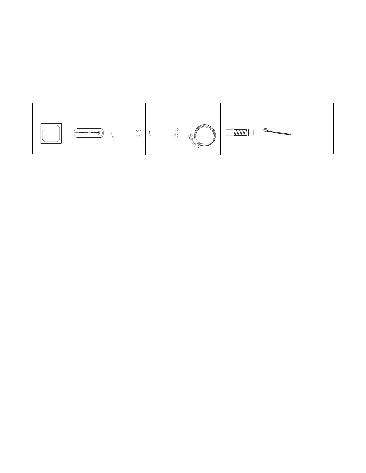
In addition to product literature, the following accessories are supplied with this unit. The type and
quantity may differ, depending on the model.
Template Insulation A Insulation B Insulation C
Note: The required panel is not included with the indoor unit. It must be ordered separately
(Model #TVEPANPC4NUSET).
Location Considerations
When deciding on a location for the indoor unit, the following factors must be considered:
• The air inlet and outlet must be unobstructed.
• The wall or ceiling must support the weight of the unit.
• The wall or ceiling must not be subject to vibration.
• Pre-plan for easy and short routing
• The air must circulate freely in
• Sufficient clearance must be m
• Condensate must be managed correctly and safety away from the
• The unit should be installed in a way that prevents unauthorized access.
• The unit must not be installed in an area that is damp or could come into contact with water
h as a laundry room).
(suc
• The unit must not be exposed to direct su
• The filter must be able to be removed and cleaned easily.
• The unit should be placed as far as possible from
subject to interference.
• Care should be taken to prevent harmonics generated
proximity to a running unit.
• The unit must not be installed in an area that is exposed to salt, machine oil, sulfide gas, or
rosive environmental conditions.
cor
Flexible hose
clamp Flexible hose Cable tie Conduit bracket
of the refrigerant tubing and wiring to the outdoor unit.
the area to be cooled/heated.
aintained around the unit.
unit.
nshine or to other direct heat sources.
fluorescent lights so the remote control is not
by loose or unsupported material in close
MS-SVX039A-EN 5
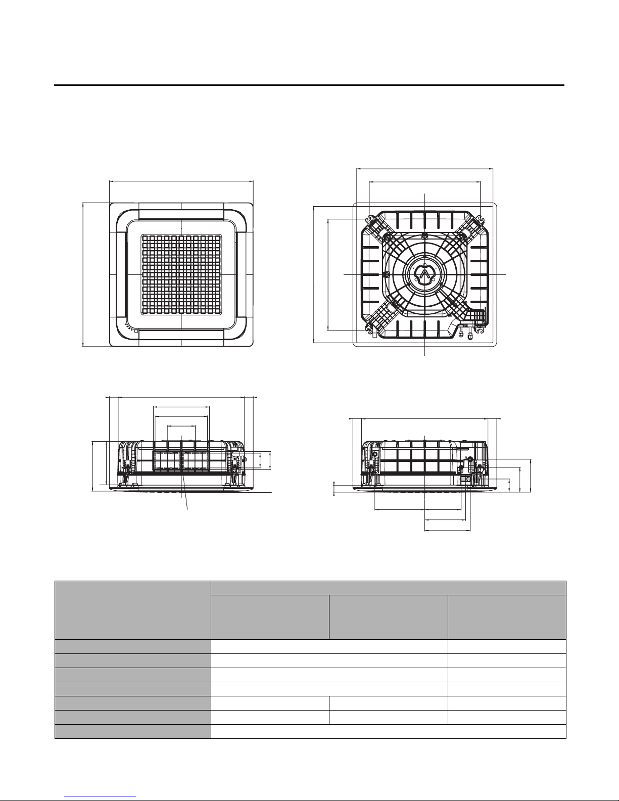
Preparing for Installation
37.4 (950)
28.94 (735) suspension position
35.04–35.83 (890–910) ceiling opening
37.4 (950)
35.04–35.83 (890–910) ceiling opening
28.94 (735) suspension position
1.77 (45)
4.72 (120)
3.78 (96)
8.5 (216)
6.46 (164)
3.39 (86)
B
A
33.07 (840)
2.17 (55) 2.17 (55)
33.07 (840)
2.17 (55)
14.57 (370)
13.6 (346)
7.28 (185)
13 (330) 9.5 (240)
10.6 (270)
11.8 (300)
Sub duct connection
Unit: inch (mm)
Unit Dimensions
6 MS-SVX039A-EN
Dimension/Weight/Diameter
A
B
Net dimension
Net weight
Liquid pipe connection
Gas pipe connection
Drain hose connection
Model
4MUC4518A10N0A 4MUC4524A10N0A
8 (204) 11.3 (288)
10 (253) 13.3 (337)
OD: 0.98 (25), ID: 0.79 (20)
33 x 8 x 33 (840 x 204 x 840) 33 x 11.3 x 33 (840 x 288 x 840)
34.2 lb (15.5 kg) 41.9 lb (19 kg)
1/4 (6.35) 1/4 (6.35) 3/8 (9.52)
1/2 (12.70) 5/8 (15.88) 5/8 (15.88)
4MUC4530A10N0A
4MUC4536A10N0A
4MUC4542A10N0A
4MUC4548A10N0A
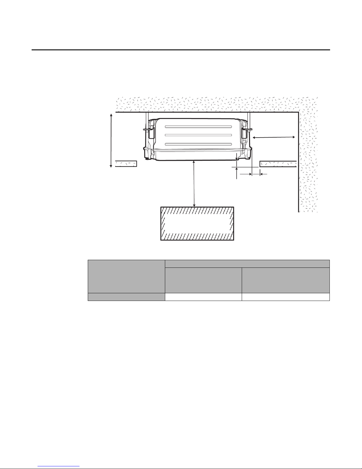
Service Clearances
Obstruction
59 (1500) minimum
0.79 (20)
0.67 (17)
9
8
.
4
(
2
5
0
0
)
mi
n
.
C
Preparing for Installation
Model
4MUC4530A10N0A
Clearance
4MUC4518A10N0A
4MUC4524A10N0A
C
10 (253) 13.3 (337)
4MUC4536A10N0A
4MUC4542A10N0A
4MUC4548A10N0A
MS-SVX039A-EN 7

Installation
A
B
Ceiling support
Concrete
Pre-poured anchor
Drill hole for anchor
Field-supplied suspension
bolts (M10 or 3/8 in.)
Isolator
Bracket
Washers, isolators, or spacers
Threaded rod should not protrude more than
1.2 in (30 mm) below the top of the bracket
Review “Installation Considerations” before proceeding with installation.
Follow the procedures in these sections in the order given.
Mounting the Unit
If the ceiling is already constructed, piping must be laid into position before placing the unit inside
the ceiling.
Avoid equipment damage and personal injury!
Ensure that the ceiling is strong enough to support the weight of the indoor unit. Before
hanging the unit, test the strength of each of the attached suspension bolts.
To mount the unit:
1. Place the template on the spot where the unit is to be installed and mark the holes.
Note: The template may shrink or stretch slightly due to heat or humidity. Before drilling holes,
2. Determine the appropriate type of suspension bolts and anc
Insert bolt anchors into existing ceiling supports (A) or construct a suitable support (B).
CAUTION
verify proper dimensions between the marks. Refer to “Installing the Front Panel” for
final finishing clearances.
hors according to the ceiling type.
3. Install suspension bolts at all four locations.
4. Screw two nuts to each suspensio
Note: If the suspension bolts ar
isolators on the brackets to absorb vibrations.
5. Hang the unit by its support brac
6. If pad stoppers or isolators are used to absorb vibrations, place them on the brackets.
7. Tighten the nuts to suspend
8. Maintain proper spacing between
8 MS-SVX039A-EN
n bolt, leaving space between the nuts for hanging the unit.
e longer than 59 in. [1.5 m]) or vibrations are a concern, place
kets between the two nuts.
the unit following the guidelines in the figure below.
the unit and the ceiling; refer to the following figure.

9. Adjust the level of the unit with a leveler.
Indoor unit
Gauge
Ceiling
0.79 in. (20 mm)
0.67 in. (17 mm)
Gas refrigerant port
Liquid refrigerant port
Purging the Unit
The unit is shipped from the factory with a holding charge of nitrogen. All of this gas must be
purged from the unit.
To purge the unit, unscrew the pinch pipes from the ends of both gas and liquid refrigerant pipes.
Make sure all gas has escaped before connecting the piping.
Note: To prevent dirt or foreign objects from getting into the pipes during installation, do not
Installation
remove the pinch pipes completely until you are ready to connect the piping.
MS-SVX039A-EN 9
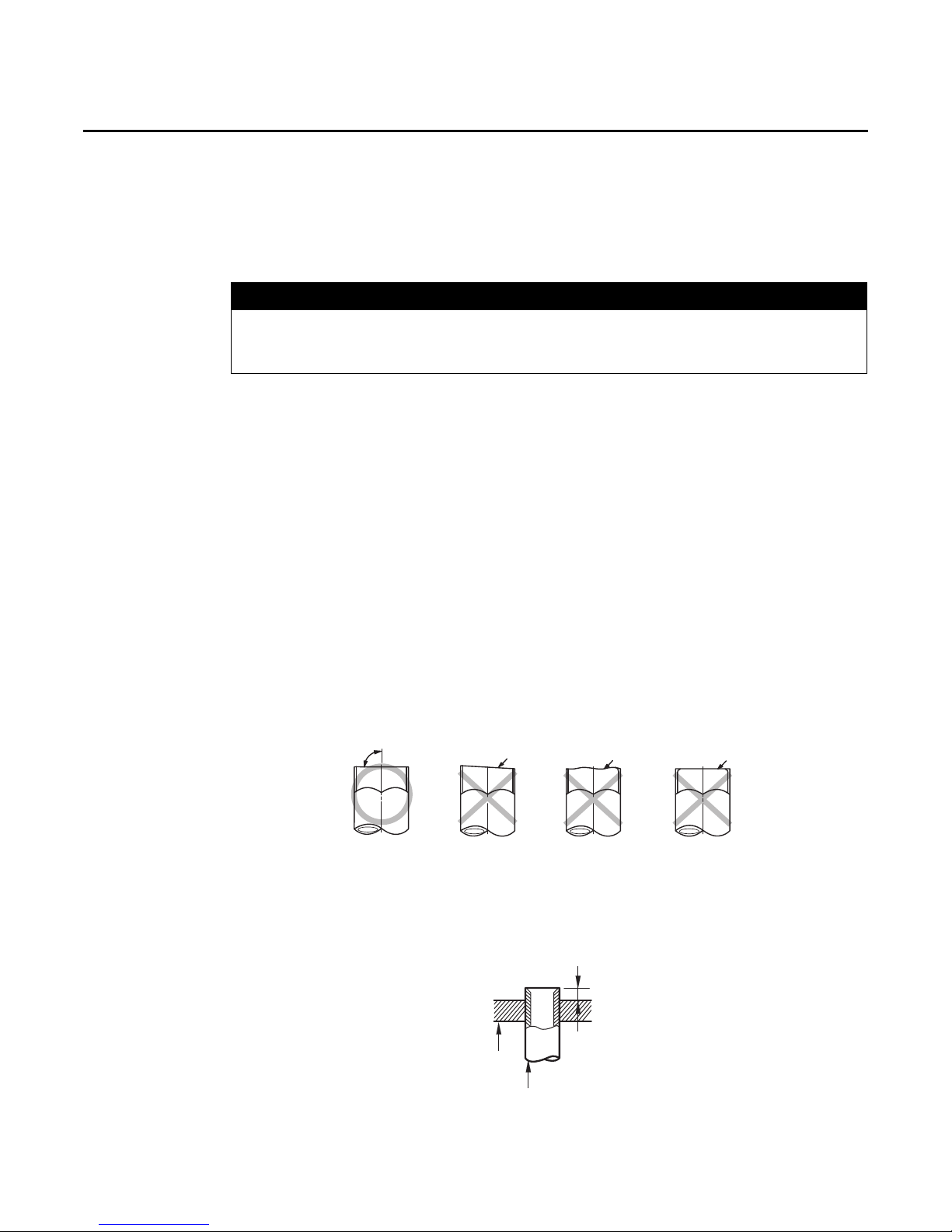
Installation
Correct: 90º
Oblique
Rough
Burr
Length of pipe extending above flare bar
Pipe
Flaring
bar
Installing Refrigerant Piping
Connect field-supplied piping using flared connections (not supplied) or by brazing. The large unit
port is for gas refrigerant; the small one is for liquid refrigerant.
Cut or extend field-supplied piping as needed. Use the following procedures.
System Failure!
If brazing is used for pipe connections, a nitrogen purge is required to prevent the formation of
copper oxides inside the piping. Failure to follow this procedure could damage the system.
• Before connecting the pipes, make sure they are free of dirt and debris.
• Use insulated, unwelded, degreased,
ISO 1337 or UNI EN 12735-1) suitable for an operating pressure of at least 609.15 psi (4200 kPa)
and a burst pressure of at least 3002.28 psi (20,700 kPa). Copper pipe for hydro-sanitary
ications is unsuitable.
appl
• For sizing and limits (height difference, line le
so on) see the outdoor unit installation manual.
• All refrigerant connections must be accessible f
Pipe Cutting
Required tools:
•Pipe cutter
•Reamer
• Pipe holder
1. Using a pipe cutter, cut the pipe so that the cut edge is at 90° to the side of the pipe.
2. Use a reamer to remove all burrs at the cut edge.
See examples of correctly and incorrectly cut pipes.
NOTICE
and deoxidized copper pipe (Cu-DHP type according to
ngth, maximum bends, refrigerant charge, and
or servicing and maintenance.
Flared Pipe Connections
Clutch type and wing nut type flare tools are available for flared pipe connections.
1. Slide the flare nut over the pipe to be flared.
2. Slide the end of the pipe into the h
pipe, determined by tool type (see table), extending above the flaring bar. Clamp it down.
10 MS-SVX039A-EN
ole on the flaring bar that fits the pipe, leaving a length of
 Loading...