

Page 1

TRN-2012/TRN-2113
Integration Specification
On-Ramp Wireless Confidential and Proprietary. This document is not to be used, disclosed, or distributed to
anyone without express written consent from On-Ramp Wireless. The recipient of this document shall respect t he
security of this document and maintain the confidentiality of the information it contains. The master copy of this
document is stored in electronic format, therefore any hard or soft copy used for distribution purposes must be
considered as uncontrolled. Refer en ce should be mad e to On-Ramp Wireless to obtain the latest revision.
Page 2

On-Ramp Wi reless Incorporated
10920 Via Frontera, Suite 200
San Diego, CA 92127
U.S.A.
Copyright © 2013 On-Ramp Wireless Incorporated.
All Rights Reserved.
The information disc lose d i n th is document is proprietary to On-Ram p Wireless Inc., and is not to be used
or disclosed to una uthorized persons without the written c onsent of On-Ramp Wireless. The recipient of
this document shall respect the security of this document and maintain the confidentiality of the
information it contains. The master copy of this document is stored in electronic format, therefore any
hard or soft copy used for distribution purposes m ust be considered as uncontrolled. Referenc e should
be made to On-Ramp W ir eless to obtai n the lates t vers ion. By accepting this material the recipient agrees
that this material and the in form ation contai ned therei n is to be held in conf idence and i n trus t and wi ll no t
be used, copied, r eprod uc e d i n whol e or i n p art, nor its contents revealed in any manner to others with out
the express written permission of On-Ramp Wi reless Incorporated.
On-Ramp Wireless Incorporated reserves the right to make changes to the product(s) or information
contained herein wit hout notice. No liability is as sumed for any damages ar ising directly or indirectl y by
their use or application. The information provided in this document is provided on an “as is” basis.
This document contains On-Ramp Wireless proprietary information and must be shredded when
discarded.
This documentation and the software described in it are copyrighted with all rights reserved. This
documentation and the software may not be copied, except as otherwise provided in your software
license or as expressly permitted in writing by On-Ramp Wireless, Incorporated.
Any sample code herein is provided for your conve nience and has not been tested or designed to work
on any particular system configuration. It is provi ded “AS IS” and your use of this sample code, whether
as provided or with an y modification, is at your own risk. On-Ramp Wireless undertakes no liability or
responsibility with respect to the sample code, and disclaims all warranties, express and implied,
including without limitation warranties on merchantability, fitness for a specified purpose, and
infringement. On-Ram p Wireless reserves all rights in the sample code, and permits us e of this sample
code only for educational and reference purposes.
This technology and technical data may be subject to U.S. and inter national expo rt, re-export or transfer
(“export”) laws. Diversion contrary to U.S. and international law is strictly prohibited.
Random Phase Multiple Access™ is a trademark of On-Ramp Wireless Incorporated.
Other product and brand names may be trademarks or registered trademarks of their respective owners.
TRN-2012 / TRN-2113 Integr atio n Specif ication
014-0047-00 Rev. C
May 13, 2013
Page 3

Contents
1 Overview ................................................................................................................ 1
1.1 On-Ramp Wireless Total Reach Network .................................................................................. 1
1.2 Model Numbers .......................................................................................................................... 2
1.3 Referenced Documents ............................................................................................................. 2
2 DC and RF Characteristics ................................................................................... 3
2.1 Absolute Maximum Ratings ....................................................................................................... 3
2.2 Recommended Operating Conditions ........................................................................................ 3
2.3 Operating Characteristics for all Models .................................................................................... 3
2.4 Power Supplies .......................................................................................................................... 4
3 Electrical Interface ................................................................................................ 5
3.1 Signal Connectors ...................................................................................................................... 5
3.2 Pin and Signal Descriptions ....................................................................................................... 7
3.2.1 Main signal connector ....................................................................................................... 7
3.2.2 RF Connectors ................................................................................................................. 7
3.3 Environmental ............................................................................................................................ 7
3.3.1 ESD .................................................................................................................................. 7
3.3.2 Harsh Environments ......................................................................................................... 8
4 Safety Considerations .......................................................................................... 9
5 Regulatory Considerations ................................................................................ 10
5.1 Block Diagrams ........................................................................................................................ 10
5.2 Antennas .................................................................................................................................. 11
5.3 EMC Certifications ................................................................................................................... 12
5.4 FCC Warnings .......................................................................................................................... 12
5.5 ETSI Warnings ......................................................................................................................... 13
5.6 Usage ....................................................................................................................................... 13
5.6.1 Product Labels ................................................................................................................ 13
5.6.2 RF Exposure Statement ................................................................................................. 14
5.7 WEEE Directive ........................................................................................................................ 15
5.8 REACH Directive ...................................................................................................................... 15
5.9 RoHS Directive ......................................................................................................................... 15
6 Installation of TRN-2012/TRN-2113 Boards ...................................................... 16
7 Operating and Troubleshooting ........................................................................ 18
7.1 Operating ................................................................................................................................. 18
7.2 Troubleshooting ....................................................................................................................... 19
7.3 RMA Process ........................................................................................................................... 19
On-Ramp Wireless Confidential and Proprietary iii 014-0047-00 Rev. C
Page 4

TRN-2012 / TRN-2113 Integration Specification Contents
8 Provisioning ........................................................................................................ 20
8.1 Manual Provisioning ................................................................................................................. 20
8.2 Automatic Provisioning ............................................................................................................ 21
Appendix A Provisioning Process and Work Flow ............................................. 22
Appendix B Test Mode Interface .......................................................................... 23
B.1 Normal Operating Mode 0 ....................................................................................................... 23
B.2 Non-Persistent Idle / Factory Test Mode 1 .............................................................................. 23
B.3 Persistent Idle / Factory Test Mode 2 ...................................................................................... 23
B.4 Non-Persistent Node RF Test Mode 3 .................................................................................... 23
B.5 Persistent Node RF Test Mode 4 ............................................................................................ 24
B.6 Non-Persistent Manufacturing Cal Mode 5 ............................................................................. 24
B.7 Persistent Manufacturing Cal Mode 6 ..................................................................................... 24
B.8 Non-Persistent Meter Diagnostic Mode (Not Yet Implemented) ............................................. 25
B.9 Setting eMCM to Test Mode 1 - Non-Persistent Idle Factory Test Mode ................................ 25
B.10 Setting eMCM to Test Mode 2 - Persistent Idle Factory Test Mode ..................................... 26
B.11 Setting eMCM to Test Mode 3 - Non-Persistent RF Test Mode ............................................ 26
B.12 Setting eMCM to Test Mode 4 - Persistent RF Test Mode .................................................... 27
Appendix C REACH Compliance Statements ...................................................... 28
Appendix D Abbreviations and Terms ................................................................. 30
Appendix E TRN-2012 / TRN-2113 Mechanical Drawings and Schematics ....... 32
Figures
Figure 1. On-Ramp Wireless Total Reach Network ......................................................................... 1
Figure 2. TRN-2012 with Internal Antennas (Top and Bottom Views) ............................................. 5
Figure 3. TRN-2113 with E x ternal Ant enn as (T op and Bottom Views) ........................................... 6
Figure 4. Meter Test Connection Diagram ....................................................................................... 9
Figure 5. Block Diagram for TRN-2012 with Internal Antennas ..................................................... 10
Figure 6. Block Diagram for TRN-2113 with External Antennas ................................................... 11
Figure 7. TRN-2012 Product Label ................................................................................................ 14
Figure 8. TRN-2113 Product Label ................................................................................................ 14
Figure 9. Carton Label ................................................................................................................... 14
Figure 10. Meter Assembly with TRN-2012 or TRN-2113 Board .................................................. 16
Figure 11. Detail of TRN-2012 or TRN-2113 Board Mounting in Plastic Case .............................. 17
Figure 12. Manual Provisioning with Provisioning Cable and USB Isolator .................................. 20
Figure 13. Provisioning Cable for TRN-2012 and TRN-2113 ........................................................ 20
Figure 14. Mechanical Dimensions for TRN-2012 and TRN-2113 ................................................ 32
Figure 15. Schematics for TRN-2012 and TRN-2113 .................................................................... 33
On-Ramp Wireless Confidential and Proprietary iv 014-0047-00 Rev. C
Page 5

TRN-2012 / TRN-2113 Integration Specification Contents
Tables
Table 1. Absolute Maximum Ratings ............................................................................................... 3
Table 2. Operating Condit io ns ......................................................................................................... 3
Table 3. Operating Charac t eris tics .................................................................................................. 3
Table 4. Pins and Signals for J500 Signal and Power Connector ................................................... 7
Table 5. ESD Rating ........................................................................................................................ 7
Table 6. On-Ramp Wireless EMC Certified Antenna ..................................................................... 11
Table 7. TRN-2012 / TRN-2113 EMC Compliance Certifications .................................................. 12
Table 8. Troubleshooting Guidelines ............................................................................................. 19
Table 9. LED Blinking Patterns/States ........................................................................................... 19
On-Ramp Wireless Confidential and Proprietary v 014-0047-00 Rev. C
Page 6

New chapter on Operating and Troubleshooting
Revision History
Revision Release Date Change Description
A December 4, 2012 Initial release
B March 11, 2013 Updated:
C May 13, 2013 Updated product names, block diagrams, and
Document reference l ist in the Overview chapter
Provisioning Process and Work Flow information
Added:
regulatory/certificat ion inf ormation.
On-Ramp Wireless Confidential and Proprietary vi 014-0047-00 Rev. C
Page 7
1 Overview
The purpose of this document is to provide guidelines allowing an integrator to design a host
product that uses the TRN-2012 MCM (Meter Communications Module) or the TRN-2113 MCM
and ensures that the system meets all of its technical objectives and requirements.
1.1 On-Ramp Wireless Total Reach Network
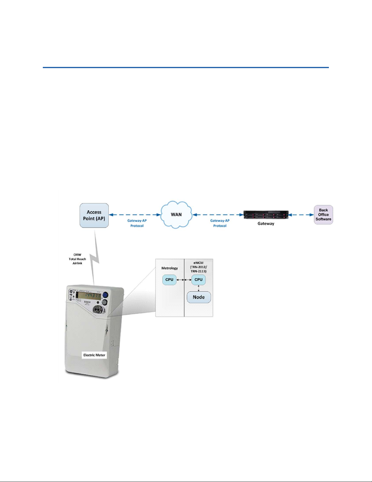
The On-Ramp Wireless Total Reach Network is comprised of host modules, such as TRN2012/TRN-2113 modules equipped with microNodes, and Access Points (APs). The network
operates in the unlicensed 2.4 GHz ISM band. The TRN-2012 and TRN-2113 circuit boards are
designed to easily integrate into electric meters, through standard interfaces, enabling robust
wireless communication with one or more APs interfaced with a service provider’s local or wide
area network.
Figure 1. On-Ramp Wireless Total Reach Network
On-Ramp Wireless Confidential and Proprietary 1 014-0047-00 Rev. C
Page 8

TRN-2012 / TRN-2113 Integration Specification Overview
1.2 Model Numbers
TRN-2012 with internal antennas
TRN-2113 with external antennas
1.3 Referenced Documents
The following documents are referenced and provide more detail:
Test Mode Software Interface
Appendix B of this manual provides details relating to the Test Mode Interface.
TRN-2012 and TRN-2113 ETSI EMC Test Reports
The EMC Test Reports from third party labs authorized to conduct these tests.
Provisioning Guide (010-0074-00)
Describes setup, configuration, and use of a collection of utilities called Node Provisioning
Tools (NPT) used for Node provisioning.
Node Host Message Specification (014-0020-00)
Provides details relating to Node Host commands and messages.
GE Energy, Operating Level Procedure (OLP): On-Ramp Wireless’ Meter Communication
Module
Describes the incoming/outgoing inspection and RMA process.
On-Ramp Wireless Document 008-0013-00, Process, Return Material Authorization (RMA)
Describes the handling and RMA process between GE and On-Ramp Wireless.
On-Ramp Wireless Confidential and Proprietary 2 014-0047-00 Rev. C
Page 9
2 DC and RF Characteristics
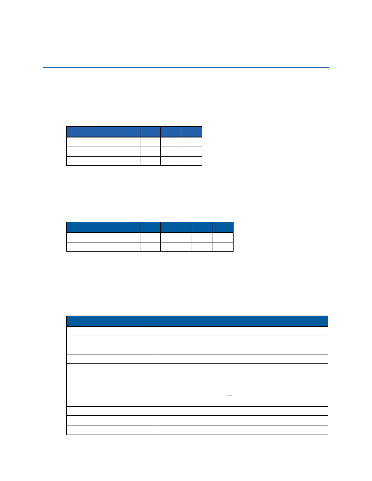
2.1 Absolute Maximum Ratings
Operation outside of the Absolute Maximum Ratings may damage the module.
Table 1. Absolute Maximum Ratings
Parameter Min Max Unit
Storage Temperature (Ts) -40 85
Ambient Temperature (Ta) -40 85
Input Voltage (VBATT) 0.0 18.0 V
⁰C
⁰C
2.2 Recommended Operating Conditions
Operation outside of the Recommended Operating Conditions may not yield proper operation.
Table 2. Operating Conditions
Parameter Min Nominal Max Unit
Ambient Temperature (Ta) -40 25C 85
Input voltage (VBATT) 8.0 12.0V 16.0 V
⁰C
2.3 Operating Characteristics for all Models
The following characteristics apply across the -40°C to +85°C temperature range unless
otherwise noted.
Table 3. Operating Characteristics
Parameter On-Ramp Wireless TRN-2012 / TRN-2113 Module
Frequency 2.4 GHz ISM
Bandwidth 1 MHz nominal
Modulation Dynamic-Direct Sequence Spread Spectrum (D-DSSS)
Multiple Access Scheme Random Phase Multiple Access (RPMA)
Transmit Power (peak EiRP) +10 dBm (ETSI markets includes peak internal/external antenna
gain)
Receive Sensitivity -136 dBm (includes peak internal or external antenna gain)
Antenna Options
Data Throughput 60 kbps (at access point in 1 MHz channel bandwidth)
Maximum Allowable Path Loss 150 dB
TX Burst Time
RX Burst Time
On-Ramp Wireless Confidential and Proprietary 3 014-0047-00 Rev. C
Integrated antenna diversity or external antenna diversity
≈ 2.2 Seconds
≈ 2.5 Seconds
Page 10

TRN-2012 / TRN-2113 Integration Specification DC and RF Characteristics
Parameter On-Ramp Wireless TRN-2012 / TRN-2113 Module
Current Consumption 0.10A max. @ 12VDC (during TX1)
Operating Temperature -40°C to 85°C
Relative Humidity 5% to 95% non-condensing
Security AES 128-bit payload encryption, mutual authenticatio n of net w or k
Certifications ETSI EMC certifications are pending for the TRN-2012 and the TRN-
NOTE 1: During TX mode the supercap charger is disabled to reduce peak currents. However
under manual control (not a link) this current could be up to 0.14A.
NOTE 2: During RX mode the supercap charger is enabled. The supercap charge current is
limited to about 40mA at 12VDC input.
NOTE 3: Specifications subject to change.
2.4 Power Supplies
The TRN-2012 and the TRN-2113 utilize two main power supplies when functioning:
1. Initial Switching Power Supply and Supercap Charger (~4.4VDC output)
This buck-type switching power supply is used to lower the wide input voltage range and
charge the super capacitors. It is in use at all times when primary power is applied.
0.13A max. @ 12VDC (during RX
elements
2113. Meter ANSI and Unintentional Radiator certifications required
once integrated into the meter product.
2
)
2. Main switching power supply (3.3VDC output)
This main buck/boost switching power supply is operating at all times. It supplies power to
all digital and radio circuits. It is normally sourced by the Initial power supply. However
when primary power is interrupted the super caps become the source of power to this
regulator.
Additionally the microNode module on the TRN-2012/TRN-2113 printed circuit board has its
own switching power supply (buck-boost) that uses, as its source, the main switching power
supply (3.3V) of the TRN-2012/TRN-2113.
On-Ramp Wireless Confidential and Proprietary 4 014-0047-00 Rev. C
Page 11
Internal Antennas
2x 6-pin 0.1” Meter Interf ace Header
3 Electrical Interface
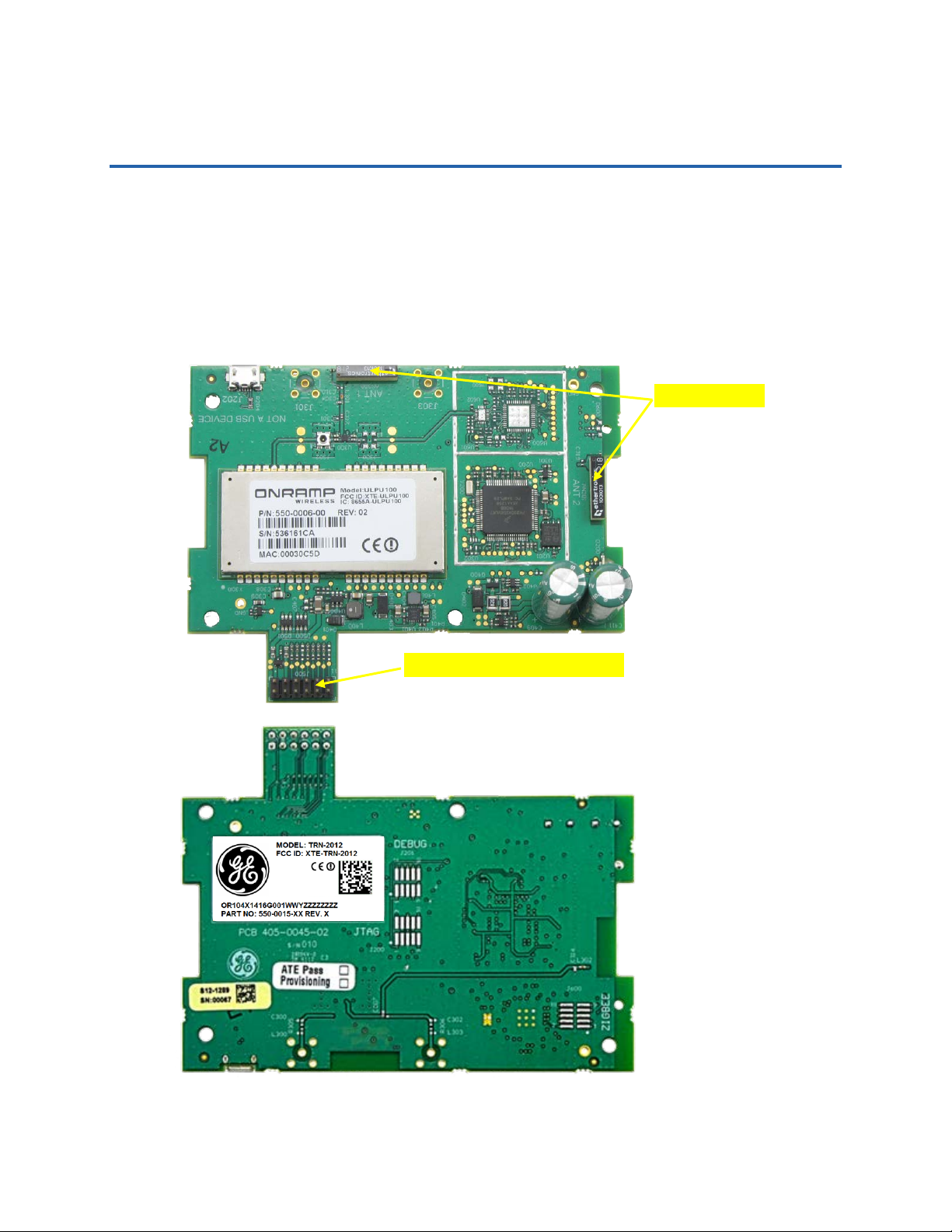
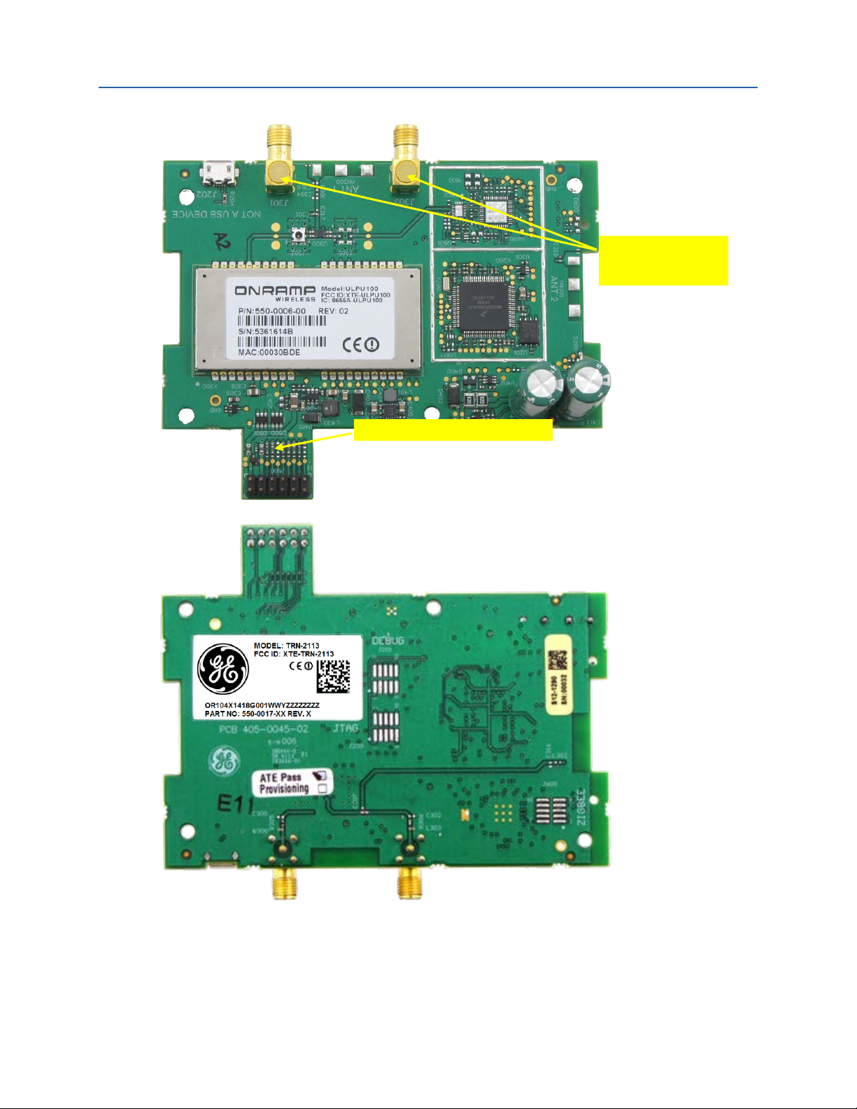
This chapter describes the electrical interface for the TRN-2012 (with internal antennas) and the
TRN-2113 (with external antennas).
3.1 Signal Connectors
Each side of the TRN-2012 and the TRN-2113 printed circuit boards is shown in Figure 2 and
Figure 3.
Figure 2. TRN-2012 with Internal Antennas (Top and Bottom Views)
On-Ramp Wireless Confidential and Proprietary 5 014-0047-00 Rev. C
Page 12
TRN-2012 / TRN-2113 Integration Specification Electrical Interface
Right-angle, RP-SMA
Headers
2x 6-pin 0.1” Meter Interf ace Header
Connectors for External
Figure 3. TRN-2113 with External Antennas (Top and Bottom Views)
On-Ramp Wireless Confidential and Proprietary 6 014-0047-00 Rev. C
Page 13
TRN-2012 / TRN-2113 Integration Specification Electrical Interface
3.2 Pin and Signal Descriptions
3.2.1 Main signal connector
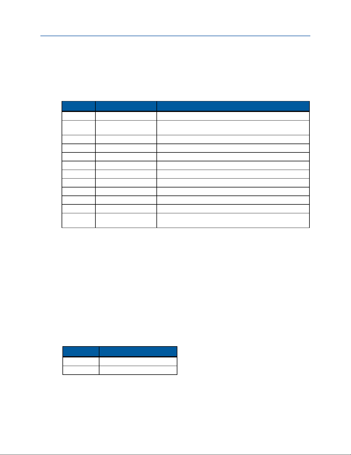
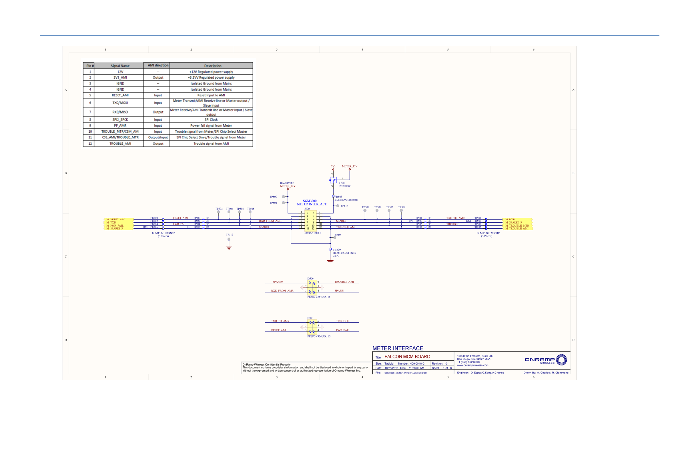
The following table lists the pins and signals for J500, the signal, and the power connector.
Table 4. Pins and Signals for J500 Signal and Power Connector
MCM Pin # Pin Name Signal Description
1 DC Power input 12VDC input to the TRN-2012 / TRN-2113 from the meter.
2 3.3VDC Power output
3 GROUND Meter ground
4 GROUND Meter ground
5 RESET_b Reset signal from meter, active low.
6 M_RXD Meter UART TXD, 9600 baud rate, 8bit data, 0 stop, 1 parity.
7 M_TXD Meter UART RXD
8 M_SPARE0_F Spare 0 is not used.
9 M_PWR_FAIL Power fail signal from meter, active low = fail.
10 M_TROUBLE_MTR Trouble signal from meter; 3.3V active high = trouble.
11 M_SPARE1_F S pare 1 is not used.
12 M_TROUBLE_AMI
3.3V regulated power supply from the TRN-2012 / TRN-2113 to
the meter interface.
Trouble signal from the TRN-2012 / TRN-2113; 3.3V active high
= trouble.
3.2.2 RF Connectors
The model TRN-2113 has two reverse polarity SMA jack connectors for connection to external
antennas. The proper mating connector is an SMA reverse polarity plug. The proper tightening
torque is 80 N-cm (7 in-lbs).
3.3 Environmental
3.3.1 ESD
The TRN-2012/TRN-2113 has ferrite beads, series resistors, and bidirectional ESD protection
diodes on its 8 digital I/O pins providing protection to
Table 5. ESD Rating
ESD Model Class and Minimum Voltage
HBM Class 1C ( >1000V)
MM Class A (>100V)
The SMA connectorized models have protection in the form of an inductor to ground, thus
allowing some robustness to direct ESD strikes. The internal antenna models are encapsulated in
the polycarbonate housing of the meter – so there is little chance of high voltages on the
antennas.
IEC 61000-4-2; level 4.
On-Ramp Wireless Confidential and Proprietary 7 014-0047-00 Rev. C
Page 14

TRN-2012 / TRN-2113 Integration Specification Electrical Interface
3.3.2 Harsh Environments
The TRN-2012 and the TRN-2113 are designed to be embedded circuit boards in an enclosed
protective shell. It is not designed to be exposed to outdoor environments without a case or
similar protection. The casing of the meter nominally provides robustness to harsh
environments and has been tested to and meets IP 54 standards.
On-Ramp Wireless Confidential and Proprietary 8 014-0047-00 Rev. C
Page 15
TRN
-
2012/TRN
-2113
J202
NOTE:
The TRN-
2012 and TRN-
2113 run off of
isolated supply, however
, many meters do
not
. For safety reasons, it is recommended
that you isolate all communications to/from
the meter.
4 Safety Considerations
Danger: High Voltages
When the TRN-2012 or TRN-2113 is integrated into a meter, high voltages may be present:
CAUTION: When the TRN-2012 or TRN-2113 is mounted in an SGM3000 series meter, the term
“GND” or “Ground” does NOT refer to Earth ground. The SGM3000 is designed to
provide isolation to the AMI module (i.e., TRN-2012 or TRN-2113); however, it is
recommended to use additional isolation as a precaution.
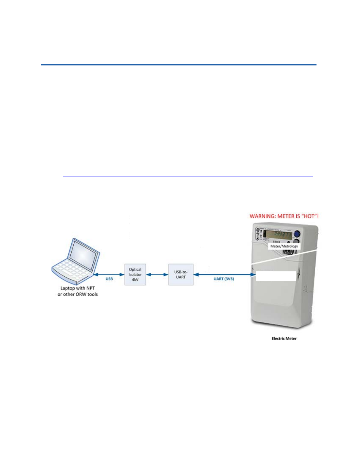
The power supply from the SGM3000 to the TRN-2012/TRN-2113 is isolated to 18kV. However,
it is recommended that you use the following isolation/drivers as an added safety precaution.
Isolator:
http://www.bb-elec.com/product_family.asp?FamilyId=651&webSyncID=85656815-ad8a-a188b050-1143ad0dee45&sessionGUID=bc450985-a6c1-9981-a0d7-6391dcb1c046
UART:
This cable is defined by On-Ramp Wireless PN 210-0023-00.
Figure 4. Meter Test Connection Diagram
On-Ramp Wireless Confidential and Proprietary 9 014-0047-00 Rev. C
Page 16
5 Regulatory Considerations
The TRN-2012 uses two integral diversity antennas for half-duplex communication. In contrast,
the TRN-2113 uses reverse polarity SMA connectors for external antenna connections. On-Ramp
Wireless provides FCC modular approval certification as well as ETSI certification for both
models. The two models were used for certification. Documents and test results are available to
system integrators for review.
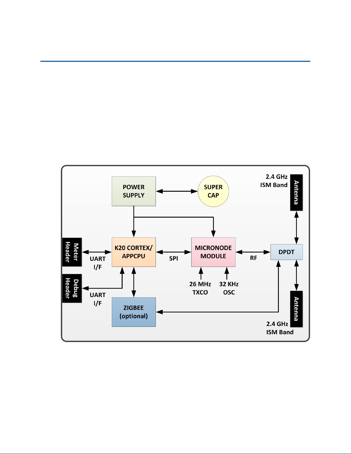
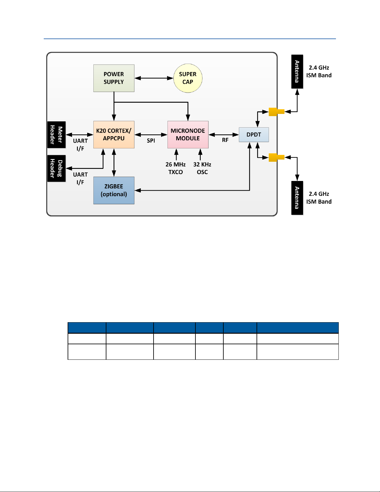
5.1 Block Diagrams
Some regulatory domains require a block diagram of the module for their documentation similar
to that shown in the following figures.
Figure 5. Block Diagram for TRN-2012 with Internal Antennas
On-Ramp Wireless Confidential and Proprietary 10 014-0047-00 Rev. C
Page 17
TRN-2012 / TRN-2113 Integration Specification Regulatory Considerations
Figure 6. Block Diagram for TRN-2113 with External Antennas
5.2 Antennas
The TRN-2012 has been certified to operate with the built-in (PCB chip) antenna (Ethertronics,
PN: 1001013) and the TRN-2113 has been certified to operate with the external paddle antenna
(L-COM, PN: SP70550). Adherence to these EMC certifications requires that only these antennas
be used. All other antennas with greater peak gain are strictly prohibited for use with the TRN2012/TRN-2113 unless new EMC certifications are obtained.
Table 6. On-Ramp Wireless EMC Certified Antenna
Product Manufacturer Part Number Gain Type Comments
TRN-2012 Ethertronics 1001013 2.1 dBi Monopole Internal PCB chip antenna
TRN-2113 L-COM SP70550 4.72 dBi Monopole
For the TRN-2113, customers are free to follow one of two paths in their final product:
Customers can use an antenna type with a gain ≤4.72 dBi. This path allows customers to use
On-Ramp Wireless’ certifications. While ideal from the perspective of program cost and
schedule, the ability to reuse this antenna is highly dependent on the application.
External SMA connectorized
paddle antenna
Customers can recertify the final product with any antenna type and gain desired. In the
case of FCC EMC certifications, it is almost always required for the final product to be
recertified with the Node. If this is the case, note that the recertification is the required time
to introduce the final product’s actual antenna.
On-Ramp Wireless Confidential and Proprietary 11 014-0047-00 Rev. C
Page 18

TRN-2012 / TRN-2113 Integration Specification Regulatory Considerations
300 440-1 and 440-2, ETSI Emissions.
5.3 EMC Certifications
The TRN-2012 and the TRN-2113 are designed to meet regulations for world-wide use. It has
EMC modular approval certifications in Europe and South Africa and certification is pending in
the United States. These certifications allow the TRN-2012 and the TRN-2113 to be installed in
any final product in Europe, South Africa, and the United States and only Unintentional Radiator
testing is required for the final product. This saves cost and time for System Integrators. The
certifications currently achieved are listed in the following table.
Table 7. TRN-2012 / TRN-2113 EMC Compliance Certifications
Country Certifying Agency Certification(s)
United States
(Certification Pending)
Europe European
South Africa ICASA
Federal
Communications
Commission (FCC)
Telecommunications
Standards Institute
(ETSI)
15.207 for power-line conducted emissions.
15.215 for RF TX bandwidth, power, conducted
and radiated emissions.
301 489-1, ETSI Immunity.
SABS CoC (EMC, based on ETSI)
The integrator of the final product is often required to do additional compliance tests. The
integration application and market will determine the specifics. The integrator is advised to
consult with local experts in compliance certifications for complete information.
FCC
Both the TRN-2012 and the TRN-2113 are Single-Modular Certified, therefore the final
product may only need Class B unintentional radiator and power-line conducted emissions
tests. This should be done with the actual production antenna.
ETSI
Europe’s system is a self-declaration system. There are no documents to submit or
certification grants to obtain. One must have the passing test results available for all
applicable requirements at any time if challenged.
Other countries will vary.
5.4 FCC Warnings
This device complies with part 15 of the Federal Communications Commission (FCC) Rules.
Operation is subject to the following two conditions:
1. This device may not cause harmful interference.
2. This device must accept any interference received, including interference that may cause
undesired operation.
Changes or modifications not expressly approved by the manufacturer could void the user’s
authority to operate the equipment.
On-Ramp Wireless Confidential and Proprietary 12 014-0047-00 Rev. C
Page 19

TRN-2012 / TRN-2113 Integration Specification Regulatory Considerations
NOTE:
This equipment has been tested and found to comply with the limits for
digital device, pursuant to Part 15 of the FCC Rules. These limits are designed to
provide reasonable protection against harmful interference in a residential
installation.
WARNING:
This equipment generates, uses, and can radiate radio frequen
installed and used in accordance with the instructions, this equipment may cause
harmful interference to radio communications. However, there is no guarantee
that interference will not occur in a particular installation. If this equipment
cause harmful interference to radio or television reception, which can be
determined by turning the equipment off and on, the user is encouraged to try to
correct the interference by one or more of the following measures:
Consult the dealer or an experienced radio/TV technician for help.
Re-orient or relocate the receiving antenna.
Increase the separation between the equipment and receiver.
Connect the equipment into an outlet on a circuit different from that to which
the receiver is connected.
5.5 ETSI Warnings
a Class B
cy energy. If not
does
None known.
5.6 Usage
FCC ID: XTE-TRN-2012 (or XTE-TRN-2113). This device is only authorized for use in fixed and
mobile applications. To meet FCC and other national radio frequency (RF) exposure
requirements, the antenna for this device must be installed to ensure a separation distance of at
least 20cm (8 inches) from the antenna to a person.
5.6.1 Product Labels
A label showing the FCC ID designator, listed above, must be affixed to the exterior of any device
containing the TRN-2012 or TRN-2113 (if the TRN-2012/TRN-2113 is not visible). The exterior
label must include: Contains FCC ID: XTE-TRN-2012 (or XTE-TRN-2113).
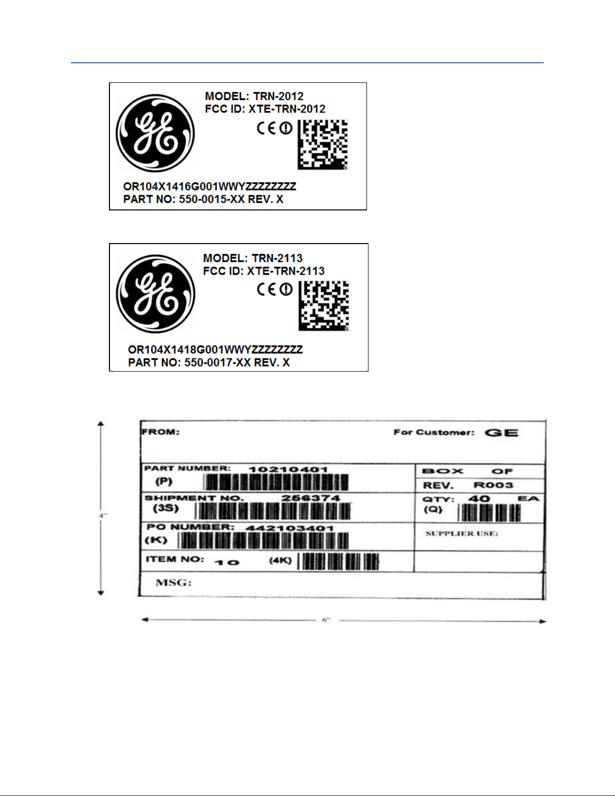
Product labels for both the TRN-2012 and the TRN-2113 are shown in Figure 7 and Figure 8. A
carton label sample is shown in Figure 9.
On-Ramp Wireless Confidential and Proprietary 13 014-0047-00 Rev. C
Page 20
TRN-2012 / TRN-2113 Integration Specification Regulatory Considerations
Figure 7. TRN-2012 Product Label
Figure 8. TRN-2113 Product Label
Figure 9. Carton Label
5.6.2 RF Exposure Statement
The air interface supports operation on channels in the 2402 MHz – 2476 MHz range for FCC/IC
regulatory domains and 2402 MHz – 2481 MHz for the ETSI regulatory domain.
On-Ramp Wireless Confidential and Proprietary 14 014-0047-00 Rev. C
Page 21

TRN-2012 / TRN-2113 Integration Specification Regulatory Considerations
Before this product becomes operational, it must undergo a commissioning procedure, during
which critical information required for operation is entered into the device and stored in nonvolatile storage. It is during the initial commissioning procedure that the regulatory domain,
under which the device will operate, is set. Subsequent configuration of the device during
operation is checked against the commissioned regulatory domain and non-permitted channels
or transmit power levels are rejected and the device will not transmit until a permissible
configuration per the commissioned regulatory domain is set.
5.7 WEEE Directive
The TRN-2012, TRN-2113, and microNode are not considered “end products” that put them
under the WEEE initiatives in the EU. The WEEE directives do not apply to the TRN-2012/TRN2113 products.
5.8 REACH Directive
As of August 2012 the TRN-2012 and the TRN-2113 are REACH compliant under 1907/2006/EC.
On-Ramp Wireless expects to receive a declaration of conformance from the Taiwan-based
manufacturer of the Node starting in September 2012. REACH compliance statements are found
in Appendix C.
5.9 RoHS Directive
The TRN-2012, TRN-2113, and Node all comply with RoHS directive 2002/95/EC. On-Ramp
Wireless has received Certificates of Conformance (CoC) for all components, printed circuit
boards and contract manufacturers for the TRN-2012, TRN-2113, and Node. Copies of the CoCs
are stored at On-Ramp Wireless and available upon request.
On-Ramp Wireless Confidential and Proprietary 15 014-0047-00 Rev. C
Page 22
6 Installation of TRN-2012/TRN-2113 Boards
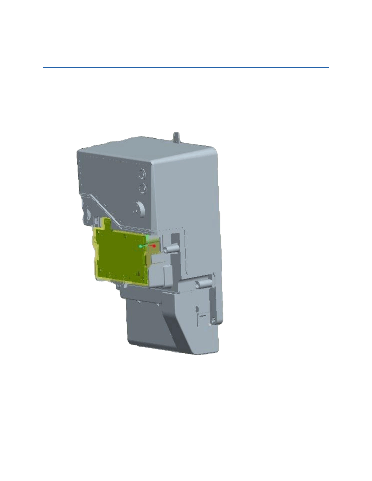
The TRN-2012 and TRN-2113 boards are simply inserted and removed as shown in the following
figures. The two plastic side tabs of the SGM30xx lock the TRN-2012/TRN-2113 module into
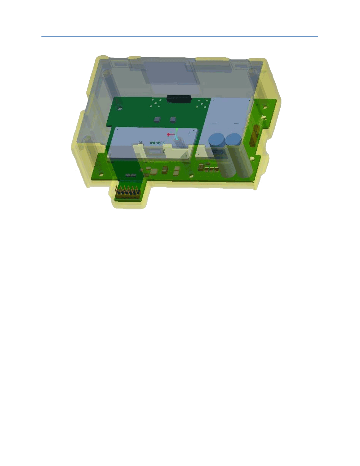
place and the 12-pin connector is easily guided into the SGM30xx connector by form fit. Figure
10 and Figure 11 show how the TRN-2012 and TRN-2113 boards are mounted inside the GE
meter.
Figure 10. Meter Assembly with TRN-2012 or TRN-2113 Board
On-Ramp Wireless Confidential and Proprietary 16 014-0047-00 Rev. C
Page 23
TRN-2012 / TRN-2113 Integration Specification Installation of TRN-2012/TRN-2113 Boards
Figure 11. Detail of TRN-2012 or TRN-2113 Board Mounting in Plastic Case
NOTE: When mounting the TRN-2113, which has external antennas, you must first remove the
perforated tabs on the plastic case to allow the antenna connectors to extend outside
the plastic case.
On-Ramp Wireless Confidential and Proprietary 17 014-0047-00 Rev. C
Page 24

7 Operating and Troubleshooting
This section provides an overview of the functionality and how best to troubleshoot a module.
7.1 Operating
The operating mode of the TRN-2012/TRN-2113 is simple in concept but has many nuances. For
a pictorial view of the system, refer to Figure 1. On-Ramp Wireless Total Reach Network.
1. When the TRN-2012/TRN-2113 powers up, it looks for a wireless Access Point (AP). This
could take up to a minute or so, depending on a number of factors.
2. The TRN-2012/TRN-2113 uses a channel list that is set up and configured during provisioning
at the factory. Provisioning configures what radio channels the APs should use and the
security keys required. The provisioned security keys keep customers isolated so that the
TRN-2012/TRN-2113 will not join a non-authorized network.
3. When the TRN-2012/TRN-2113 finds an appropriate AP, it sends a registration request to
the AP and is accepted onto the network, assuming all its security is good and intact.
4. Once enabled on the RF network, the TRN-2012/TRN-2113 can be controlled by the network
and share its meter readings with the network.
5. At a low level, the TRN-2012/TRN-2113 is connected to the SGM3000 meter via a 3.3V UART
interface (12-pin connector). The physical interface of the TRN-2012/TRN-2113 is powered
through the meter and gathers other detailed operational status of the meter. Another
signal example of the physical interface is a power fail signal. This signal, when asserted,
alerts the TRN-2012/TRN-2113 that power is about to go away; the TRN-2012/TRN-2113
then must clean up services and send a radio “power fail” message back to the network.
6. Across this physical interface, the TRN-2012/TRN-2113 communicates via an ANSI C12.19
protocol. The meter and the TRN-2012/TRN-2113 share information in this way.
7. When the network requests a demand reading of the meter’s current energy consumption,
the following occurs:
The message is sent wirelessly to the TRN-2012/TRN-2113.
The TRN-2012/TRN-2113 decodes the messages and determines the actions.
The TRN-2012/TRN-2113 sends a request to the meter.
The meter responds to the TRN-2012/TRN-2113 with the requested information.
The TRN-2012/TRN-2113 wirelessly transmits the requested information back to the
network, thus completing the action.
8. An asynchronous event in the TRN-2012/TRN-2113 is the Power Fail. When the meter
detects power has disappeared, it generates a “power fail” to the TRN-2012/TRN-2113. The
TRN-2012/TRN-2113 receives this digital signal and sends a power-fail back to the network
control center. Since there is no power from the meter, the TRN-2012/TRN-2113 resorts to
its own super-capacitors. The super-capacitors in the TRN-2012/TRN-2113 are two tall
(usually green) electrolytic capacitors. These special capacitors are charged with enough
On-Ramp Wireless Confidential and Proprietary 18 014-0047-00 Rev. C
Page 25

TRN-2012 / TRN-2113 Integration Specification Operating and Troubleshooting
energy to allow the TRN-2012/TRN-2113 to run for a period of time and transmit the
required “last gasp” message.
9. There are two LEDs (Red/Green) on the TRN-2012/TRN-2113 to indicate its status. These
LEDs help troubleshoot the status of the TRN-2012/TRN-2113 in a meter. For more
information about the LEDs, see Table 9. LED Blinking Patterns/States.
7.2 Troubleshooting
When the TRN-2012/TRN-2113 is properly inserted into the SGM3000, the LEDs blink during a
brief self-check. If the power-on is successful, the LEDs blink for only a short time. However, if
there is an issue, troubleshooting is minimal. This section provides some brief troubleshooting
guidelines.
Table 8. Troubleshooting Guidelines
Problem Action
Fatal error when powering on the
TRN-2012 / TRN-2113
TRN-2012 / TRN-2113 failed to
power on
TRN-2012 / TRN-2113 failed due
RF disadvantaged area (e.g.,
excessive folia ge or metal
objects nearby)
Note the LED color and pattern. Refer to Table 9. LED Blinking
Patterns/States to determine the cause of the failure.
Try another known working TRN-2012 / TRN-2113 module to
determine if the failure is due to the TRN-2012 / TRN-2113 module
or the SGM30xx meter.
Presuming that you are using a TRN-2012 with internal antennas
(PN 550-0045), try using the TRN-2113 that has two, 2dBi external
antennas (PN 550-0048). For more information, refer to Table 6. OnRamp Wireless EMC Certified Antenna. For installation of the TRN2012 or the TRN-2113 into the SGM30xx, refer to Chapter 6
Installation of TRN-2012/TRN-2113 Boards .
Table 9. LED Blinking Patterns/States
LED Color LED Light Pattern Activity Indicated
Green Blinks quickly – on for 0.3
seconds, off for 0.3
seconds
Green Blinks slowly – on for 1
second, off for 1 second
Red Blinks slowly Error initializing the wireless modem or getting the meter
None LEDs do not blink There is a serious error and the device is not powering on.
Node has not JOINED or the eMCM application is not in
RUN state.
The Node has not JOINED and the eMCM application is in
RUN state. In this state, the LEDs will soon turn off when the
TRN-2012/TRN-2113 reaches its run state.
information was unsuccessful.
The module is likely defective, unless the meter itself is
suspect.
7.3 RMA Process
Follow the RMA process outlined in the document entitled, Operating Level Procedure (OLP):
On-Ramp Wireless’ Meter Communication Module.
On-Ramp Wireless Confidential and Proprietary 19 014-0047-00 Rev. C
Page 26
8 Provisioning
The tools and software required for provisioning the TRN-2012/TRN-2113 are described in this
section. The Provisioning process can be handled in two main ways:
Manual for small runs
Automatic for full production
8.1 Manual Provisioning
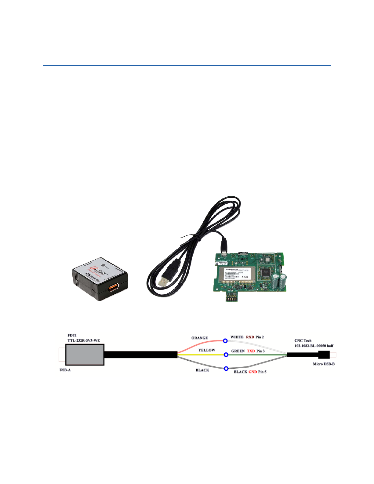
The Node Provisioning Tool (see referenced tools/documents) can be used to provision TRN2012/TRN-2113 units in small quantity. The PC attaches to the DUT (device under test) TRN2012/TRN-2113 via its Provisioning header (UART is 3.3V) and a USB Isolator, as shown in Figure
12. The J202 connector on the TRN-2012/TRN-2113 module requires a “TE Connectivity”
connector (PN 1470364-3) to mate with it, as shown in Figure 13. Use the WECO provisioning
software to provision one TRN-2012/TRN-2113 module at a time.
Figure 12. Manual Provisioning with Provisioning Cable and USB Isolator
Figure 13. Provisioning Cable for TRN-2012 and TRN-2113
CAUTION: When the TRN-2012/TRN-2113 is mounted in an SGM3000 meter, the term “GND” or
“Ground” does NOT refer to earth ground. All signals will have a 240VAC power
imposed onto those lines. All signals to/from the TRN-2012/TRN-2113 board need to
be isolated. No grounded instruments, or computers, should touch the TRN2012/TRN-2113 board signals. USE A USB ISOLATOR in the setup as shown in Figure 4.
On-Ramp Wireless Confidential and Proprietary 20 014-0047-00 Rev. C
Page 27

TRN-2012 / TRN-2113 Integration Specification Provisioning
8.2 Automatic Provisioning
The automatic process is defined and built by the customer. On-Ramp Wireless has assisted in
development of these tools but those tools are not the property of On-Ramp Wireless. The
customer owns, defines, develops, documents and maintains the manufacturing tools.
The provisioning process entails:
Loading in current versions of software to microNode and K20 processors;
Configuring (channels, TX power, etc.);
Setting and configuring security keys (via LKS server);
Performing an OTA test to ensure that the complete meter-to-TRN-2012/TRN-2113 antenna
chain is verified;
Locking down all access ports such as UART header and JTAG.
A graphical representation of the provisioning process is shown in Appendix A.
On-Ramp Wireless Confidential and Proprietary 21 014-0047-00 Rev. C
Page 28
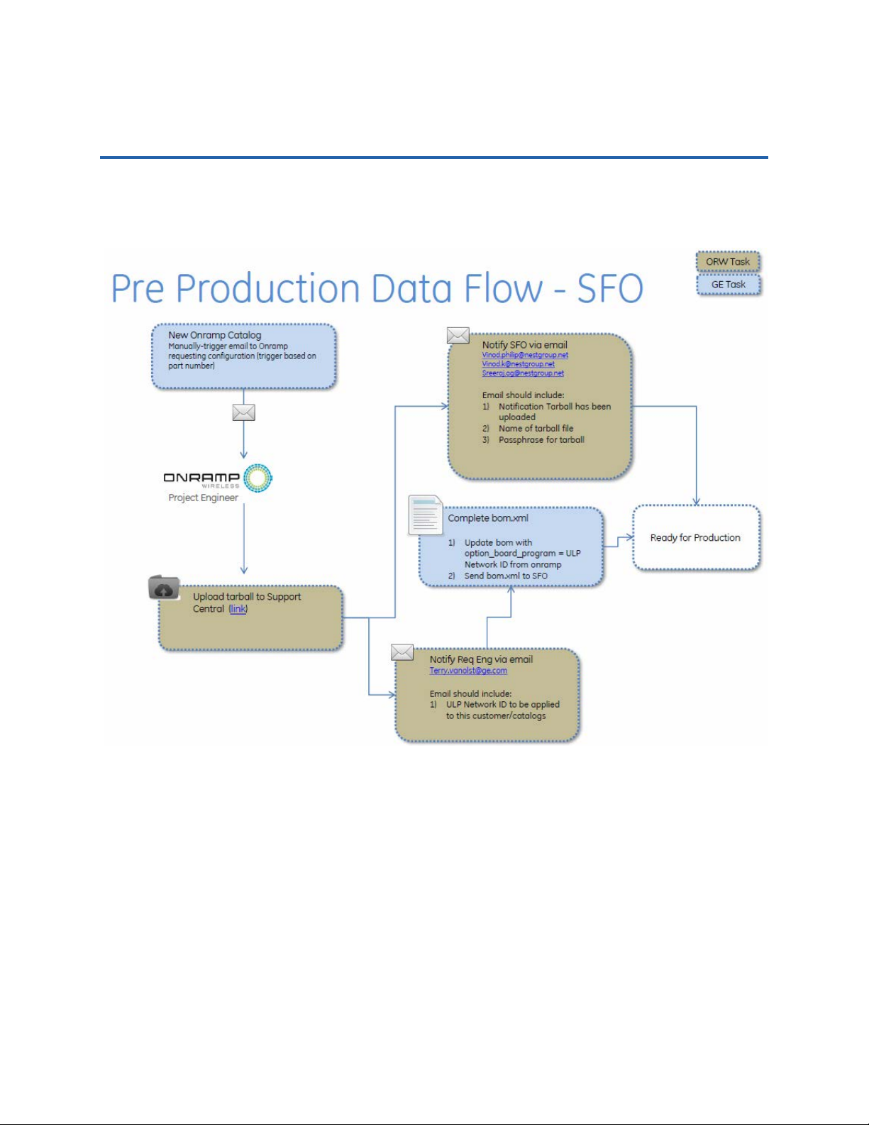
Appendix A Provisioning Process and Work Flow
The following illustration shows a graphical representation of the provisioning process.
On-Ramp Wireless Confidential and Proprietary 22 014-0047-00 Rev. C
Page 29

Appendix B Test Mode Interface
The test modes, described below, are set by setting the "testMode" parameter in the
configuration file for the eMCM.
B.1 Normal Operating Mode 0
This mode is entered based on a flash configuration setting. This mode is persistent across
boots. This is the normal operating mode of the eMCM. UNIL is initialized to communicate with
the Node. The meter software layer is initialized to communicate with the meter. Although the
eMCM is in its normal operating mode, as determined by the flash configuration setting, other
factors may subsequently cause the eMCM to change to a non-normal operating mode (e.g.,
meter is not in metering mode).
B.2 Non-Persistent Idle / Factory Test Mode 1
This mode is entered based on the testMode flash configuration setting. This mode is not
persistent across boots (self-clearing). UNIL is initialized to pass-through mode. Meter software
layer is not initialized. The UART on the AMR (automatic meter reading) serial interface is placed
in loopback mode (using the same baud rate as the meter, e.g., 9600). Same as mode 2 except
the flash testMode setting is automatically cleared to mode 0 when entering this mode. A
subsequent "set test mode" command can set the cleared value to some other test mode value.
B.3 Persistent Idle / Factory Test Mode 2
This mode is entered based on the testMode flash configuration setting. This mode is persistent
across boots. UNIL is initialized to pass-through mode. Meter software layer is not initialized.
The UART on the AMR serial interface is placed into loopback mode (using the same baud rate
as the meter, e.g., 9600). Same as mode 1 except the flash testMode setting is persistent across
boots. To exit this mode, the test mode configuration setting must be set to another value which
will take effect on eMCM reset.
B.4 Non-Persistent Node RF Test Mode 3
This mode is entered based on the testMode flash configuration setting. This mode is not
persistent across boots (self-clearing). UNIL is initialized to pass-through mode. The meter
software layer is not initialized. Same as mode 4 except the flash testMode setting is
automatically cleared to mode 0 when entering this mode. A subsequent "set test mode"
command can set the cleared value to some other test mode value.
The TX test mode is controlled by the "txTestMode" parameter in the configuration file.
1 = CW_CENTER
2 = CW_OFFSET
3 = MODULATED
On-Ramp Wireless Confidential and Proprietary 23 014-0047-00 Rev. C
Page 30

TRN-2012 / TRN-2113 Integration Specification Test Mode Interface
The antenna is controlled by the "txTestAntenna" parameter in the configuration file.
0 or 1.
The frequency is controlled by the "txTestCenterFreqKhzOffset" parameter in the
configuration file.
KHz offset from 2.4 GHz
2000 - 100000
Example: 50000 = 2.45 GHz
The VGA is controlled by the "txTestVga" parameter in the configuration file.
0 - 63, 255
The on/off duration is controlled by the "txTestModeSec" and "txTestModeUsec"
parameters in the configuration file.
B.5 Persistent Node RF Test Mode 4
This mode is entered based on the testMode flash configuration setting. This mode is persistent
across boots. UNIL is initialized to pass-through mode. The meter software layer is not
initialized. Same as mode 3 except the flash testMode setting is persistent across boots. To exit
this mode, the test mode configuration setting must be set to another value which will take
effect on eMCM reset.
B.6 Non-Persistent Manufacturing Cal Mode 5
This mode is entered based on the testMode flash configuration setting. This mode is not
persistent across boots (self-clearing). UNIL is initialized normally so that it communicates with
the Node. The meter software layer is not initialized. The UART on the AMR serial interface is
not initialized or used. Same as mode 6 except the flash testMode setting is automatically
cleared to mode 0 when entering this mode. A subsequent "set test mode" command can set
the cleared value to some other test mode value.
B.7 Persistent Manufacturing Cal Mode 6
This mode is entered based on the testMode flash configuration setting. This mode is persistent
across boots. UNIL is initialized normally so that it communicates with the Node. The meter
software layer is not initialized. The UART on the AMR serial interface is not initialized or used.
Same as mode 5 except the flash testMode setting is persistent across boots. To exit this mode,
the test mode configuration setting must be set to another value which will take effect on
eMCM reset.
On-Ramp Wireless Confidential and Proprietary 24 014-0047-00 Rev. C
Page 31

TRN-2012 / TRN-2113 Integration Specification Test Mode Interface
B.8 Non-Persistent Meter Diagnostic Mode (Not Yet
Implemented)
This mode is entered based on a flash configuration setting. This mode is not persistent across
boots (self-clearing). UNIL is initialized normally so that it communicates with the Node. The
meter software layer is initialized and communication to the meter is tested and validated. If
communication with either the Node or the meter fails (or any other error condition detected),
then the red LED is blinked with an error code indefinitely (or until the deployment mode LED
timer expires). If no errors are detected, the green LED is blinked normally to indicate network
connection state (scanning, joined, etc.). A reset is required to recover. Note: this mode may not
be needed if a basic diagnostic or POST check is done by the eMCM as part of its initialization
process.
B.9 Setting eMCM to Test Mode 1 - Non-Persistent Idle
Factory Test Mode
How to Enter
Set the 'testMode' flag in the configuration file to one.
Example: ./emcm_set_cfg.py -d /dev/ttyS0 --testMode=1
Reset the eMCM to take effect.
Example: ./emcm_dev_reset.py -d /dev/ttyS0 --emcm
How to Exit
Because this mode is non-persistent, it can be exited via an eMCM reset.
Reset the eMCM to exit the test mode. By default, the eMCM will return to normal
operational mode 0 after reset unless another mode was explicitly specified with the
emcm_set_cfg.py command prior to resetting.
Example: ./emcm_dev_reset.py -d /dev/ttyS0 --emcm
If a different mode is desired upon reset, explicitly
Description
UNIL is in pass-through mode.
Meter UART is in loopback mode.
AHP debug port is functional.
Mode is not persistent after resets.
On-Ramp Wireless Confidential and Proprietary 25 014-0047-00 Rev. C
Page 32

TRN-2012 / TRN-2113 Integration Specification Test Mode Interface
B.10 Setting eMCM to Test Mode 2 - Persistent Idle Factory
Test Mode
How to Enter
Set the 'testMode' flag in the configuration file to two.
Example: ./emcm_set_cfg.py -d /dev/ttyS0 --testMode=2
Reset the eMCM to take effect.
Example: ./emcm_dev_reset.py -d /dev/ttyS0 --emcm
How to Exit
Because this mode is persistent, it will remain in effect across eMCM resets.
Set the 'testMode' flag to the new desired mode, e.g., normal operational mode 0.
Example: ./emcm_set_cfg.py -d /dev/ttyS0 --testMode=0
Reset the eMCM for the new mode to take effect.
Example: ./emcm_dev_reset.py -d /dev/ttyS0 --emcm
Description
UNIL is in pass-through mode.
Meter UART is in loopback mode.
AHP debug port is functional.
Mode is persistent across resets.
B.11 Setting eMCM to Test Mode 3 - Non-Persistent RF Test
Mode
How to Enter
Set the 'testMode' flag in the configuration file to three.
Example: ./emcm_set_cfg.py -d /dev/ttyS0 --testMode=3
Reset the eMCM to take effect.
Example: ./emcm_dev_reset.py -d /dev/ttyS0 --emcm
How to Exit
Because this mode is non-persistent, it can be exited via an eMCM reset.
Reset the eMCM to exit the test mode. By default, the eMCM will return to normal
operational mode 0 after reset unless another mode was explicitly specified with the
emcm_set_cfg.py command prior to resetting.
Example: ./emcm_dev_reset.py -d /dev/ttyS0 --emcm
If a different mode is desired upon reset, explicitly
On-Ramp Wireless Confidential and Proprietary 26 014-0047-00 Rev. C
Page 33

TRN-2012 / TRN-2113 Integration Specification Test Mode Interface
Description
UNIL is partially operational.
Meter UART is disabled.
AHP debug port is functional.
Mode is not persistent after resets.
B.12 Setting eMCM to Test Mode 4 - Persistent RF Test Mode
How to Enter
Set the 'testMode' flag in the configuration file to four.
Example: ./emcm_set_cfg.py -d /dev/ttyS0 --testMode=4
Reset the eMCM to take effect.
Example: ./emcm_dev_reset.py -d /dev/ttyS0 --emcm
How to Exit
Because this mode is persistent, it will remain in effect across eMCM resets.
Set the 'testMode' flag to the new desired mode, e.g., normal operational mode 0.
Example: ./emcm_set_cfg.py -d /dev/ttyS0 --testMode=0
Reset the eMCM for the new mode to take effect.
Example: ./emcm_dev_reset.py -d /dev/ttyS0 --emcm
Description
UNIL is partially operational.
Meter UART is disabled.
AHP debug port is functional.
Mode is persistent across resets.
On-Ramp Wireless Confidential and Proprietary 27 014-0047-00 Rev. C
Page 34
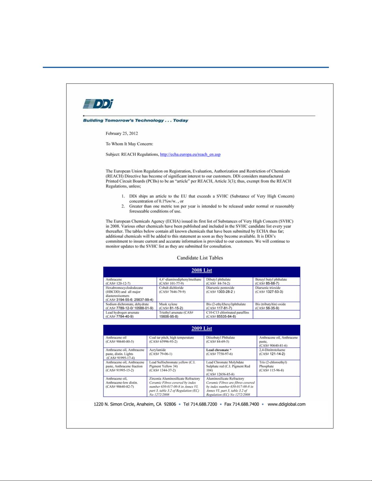
Appendix C REACH Compliance Statements
On-Ramp Wireless Confidential and Proprietary 28 014-0047-00 Rev. C
Page 35

TRN-2012 / TRN-2113 Integration Specification REACH Compliance Statements
On-Ramp Wireless Confidential and Proprietary 29 014-0047-00 Rev. C
Page 36

Appendix D Abbreviations and Terms
Abbreviation/Term Definition
AGC Automatic Gain Control
ALC Automatic Level Control
AMI Advanced Metering Infrastructure
AMR Automatic Meter Reading
AP Access Point (this product)
API Application Programming Interface
ASIC Application-Specific Integrated Circuit
BOM Bill of Materials
BW Bandwidth
CMOS Complementary Metal-Oxide-Semiconductor
CPOL Clock Polarity (for SPI)
CPU Central Processing Unit
DFS Dynamic Frequency Sele ctio n
DPLL Digital Phase-Locked Loo p
EMC Electromagnetic Compatibility
ESD Electrostatic Discharge
ETSI European Telecommunications Standards Institute
EVM Error Vector Magnitude
FCC Federal Communications Commission
FER Frame Error Rate
GND Ground
GPIO General Purpose Input/Output
HBM Human Body Model
IC Industry Canada
IIP3 Input Third-Order Intercept Point
LDO Low Drop Out
LNA Low Noise Amplifier
LO Local Oscillator
microNode The second generation of the On-Ramp Wireless module that communicates
sensor data to an Access Point. The microNode forms the basis for On-Ramp
Wireless Total Reach Network communications with the TRN-2012 / TRN-2113
products.
MISO Master Input, Slave Output
MM Machine Model
MOSI Master Output, Slave Input
MRQ Master Request
MSL Moisture Sensitivity Level
Node The generic term used interchangeably with eNode, microNode, or dNode.
On-Ramp Wireless Confidential and Proprietary 30 014-0047-00 Rev. C
Page 37

TRN-2012 / TRN-2113 Integration Specification Abbreviations and Terms
Abbreviation/Term Definition
NPT Node Provisioning Tools
On-Ramp Wireless
Total Reach
OTA Over-the-Air
PA Power Amplifier
PAPR Peak-to-Average Power Ratio
PCB Printed Circuit Board
POR Power On Reset
QoS Quality of Service
RF Radio Frequency
RFIC Radio Frequency Integrated Circuit
RoHS Restriction of Hazardous Substances
RSSI Receive Signal Strength Indicator
RT Remote Terminal
RTC Real Time Clock
RX Receive/Receiver
SCLK Serial Clock
SMT Surface Mount Technology
SNR Signal-to-Noise Ratio
SPI Synchronous Peripheral Interface
SRDY Slave Ready
SRQ Slave Request
TRN-2012
TRN-2113
TX Transmit/Transmitter
UART Universal Asynchronous Receiver/Transmitter
VCO Voltage Controlled Oscillator
VCTCXO Voltage Controlled Temperature Compensated Crystal Oscillator
VSWR Voltage Standing Wave Ratio
XO Crystal Oscillator
On-Ramp Wireless proprietary wireless communication technology.
On-Ramp Wireless AMI circuit board (PCB). An MCM for GE IEC meters with
internal antennas; Zigbee is optional.
On-Ramp Wireless AMI circuit board (PCB). An MCM for GE IEC meters with
external antennas; Zigbee is optional.
On-Ramp Wireless Confidential and Proprietary 31 014-0047-00 Rev. C
Page 38
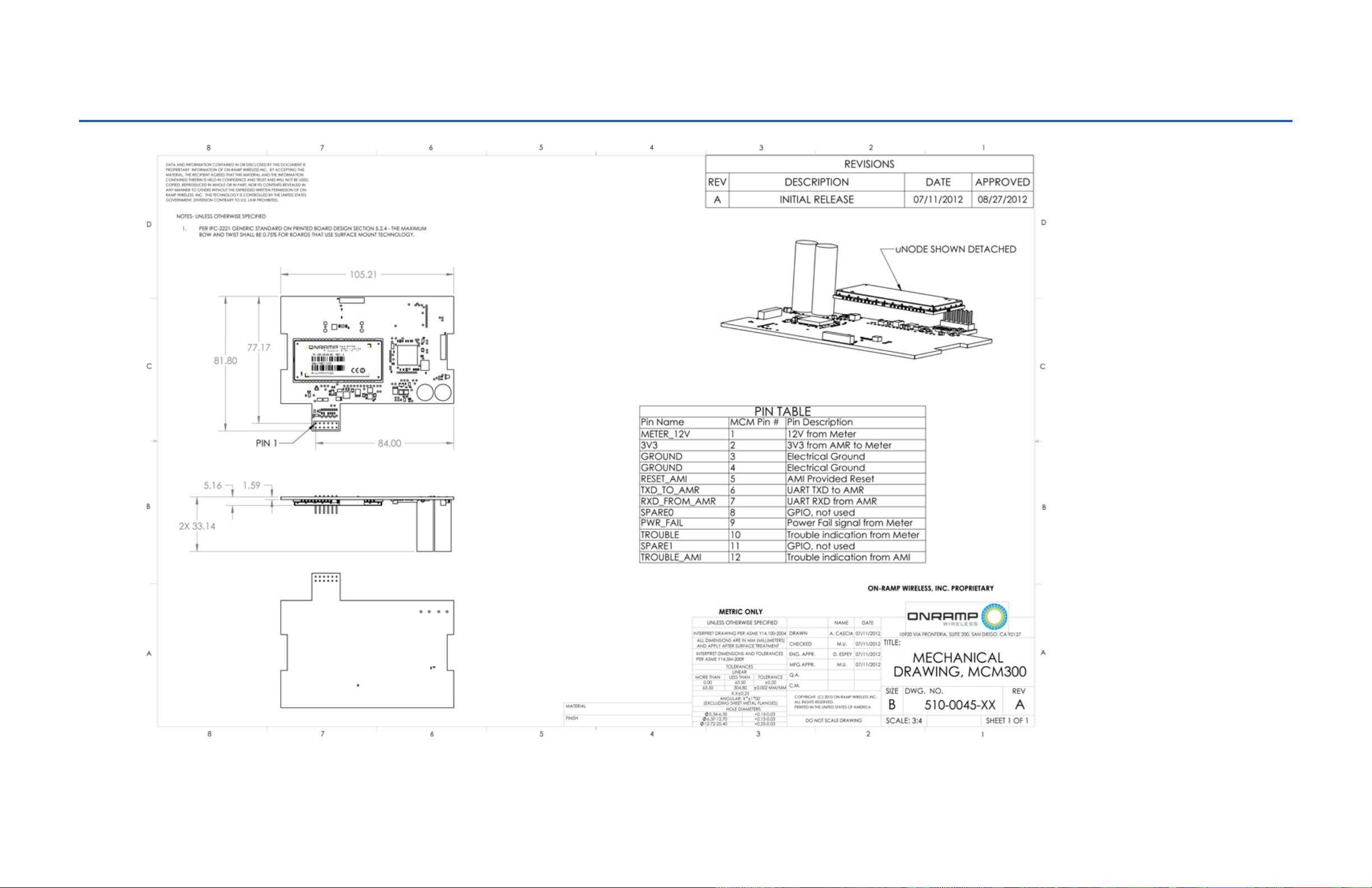
Appendix E TRN-2012 / TRN-2113 Mechanical Drawings and Schematics
Figure 14. Mechanical Dimensions for TRN-2012 and TRN-2113
On-Ramp Wireless Confidential and Proprietary 32 014-0047-00 Rev. C
Page 39
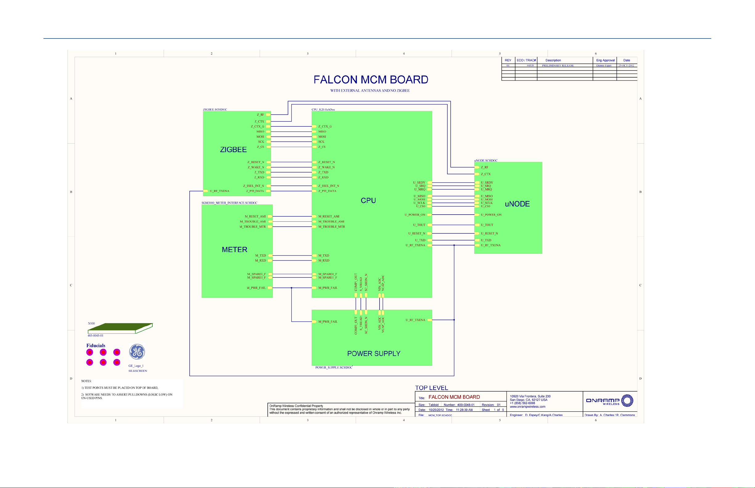
TRN-2012 / TRN-2113 Integration Specification TRN-2012 / TRN-2113 Mechanical Drawings and Schematics
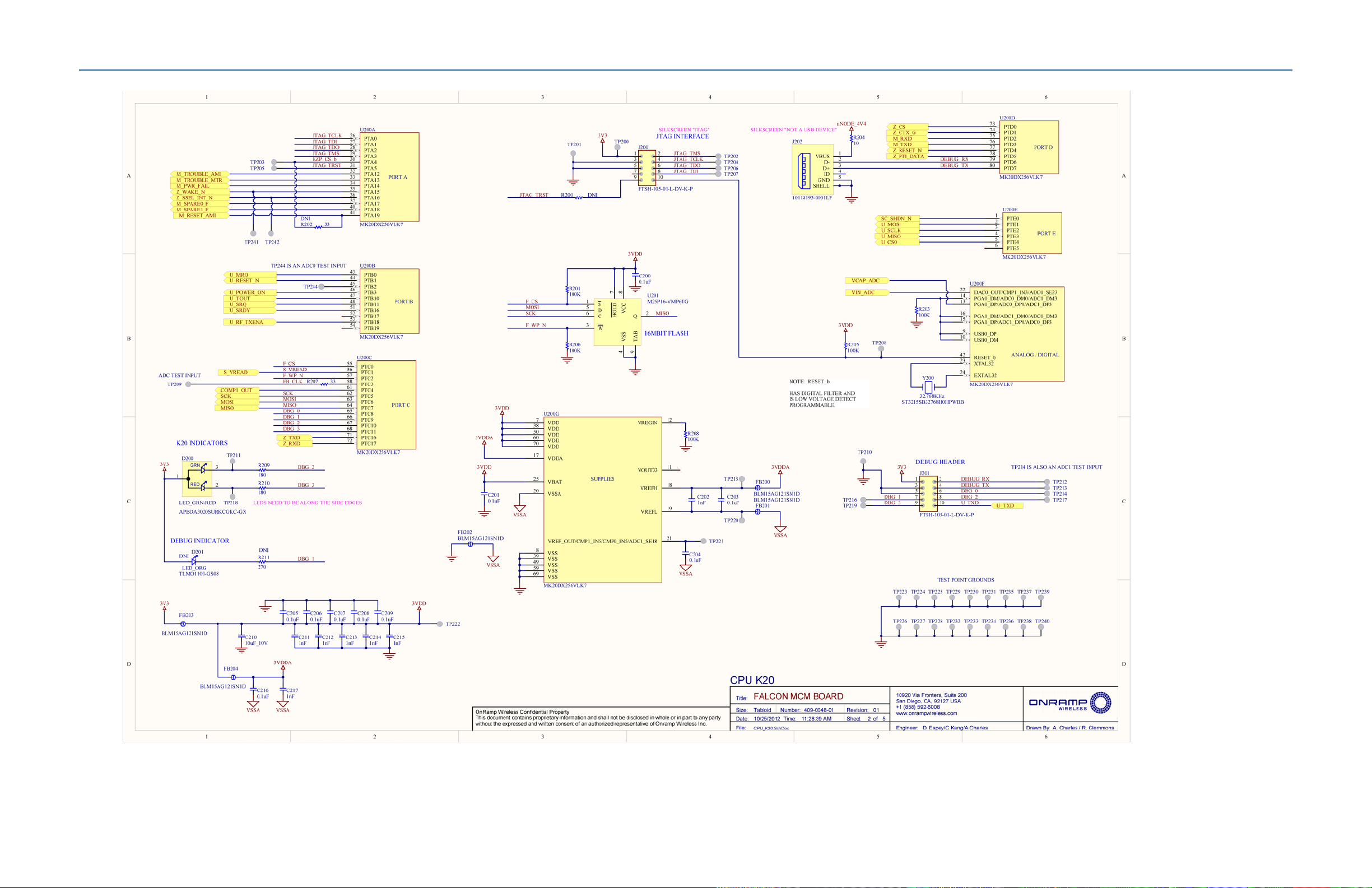
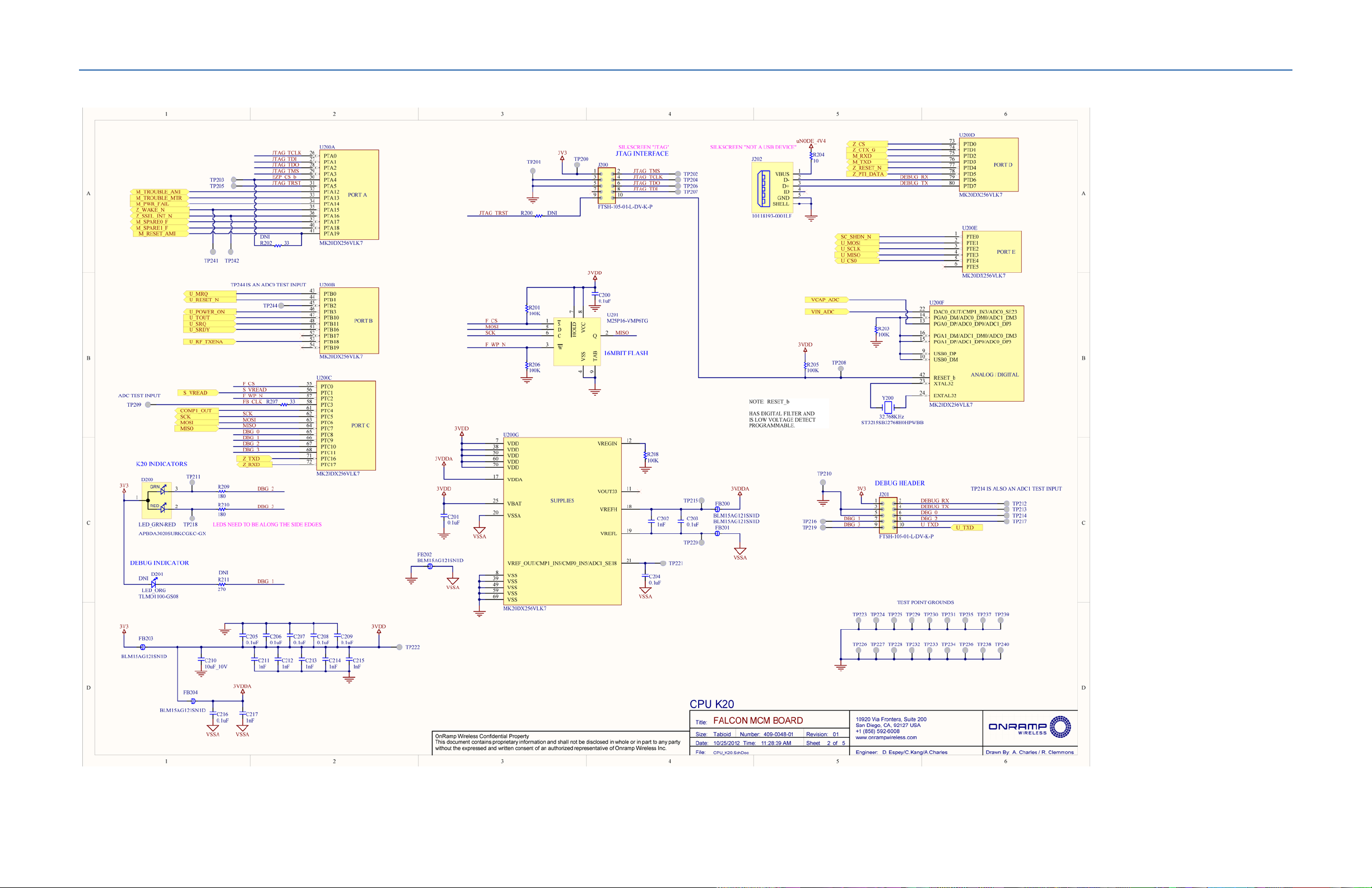
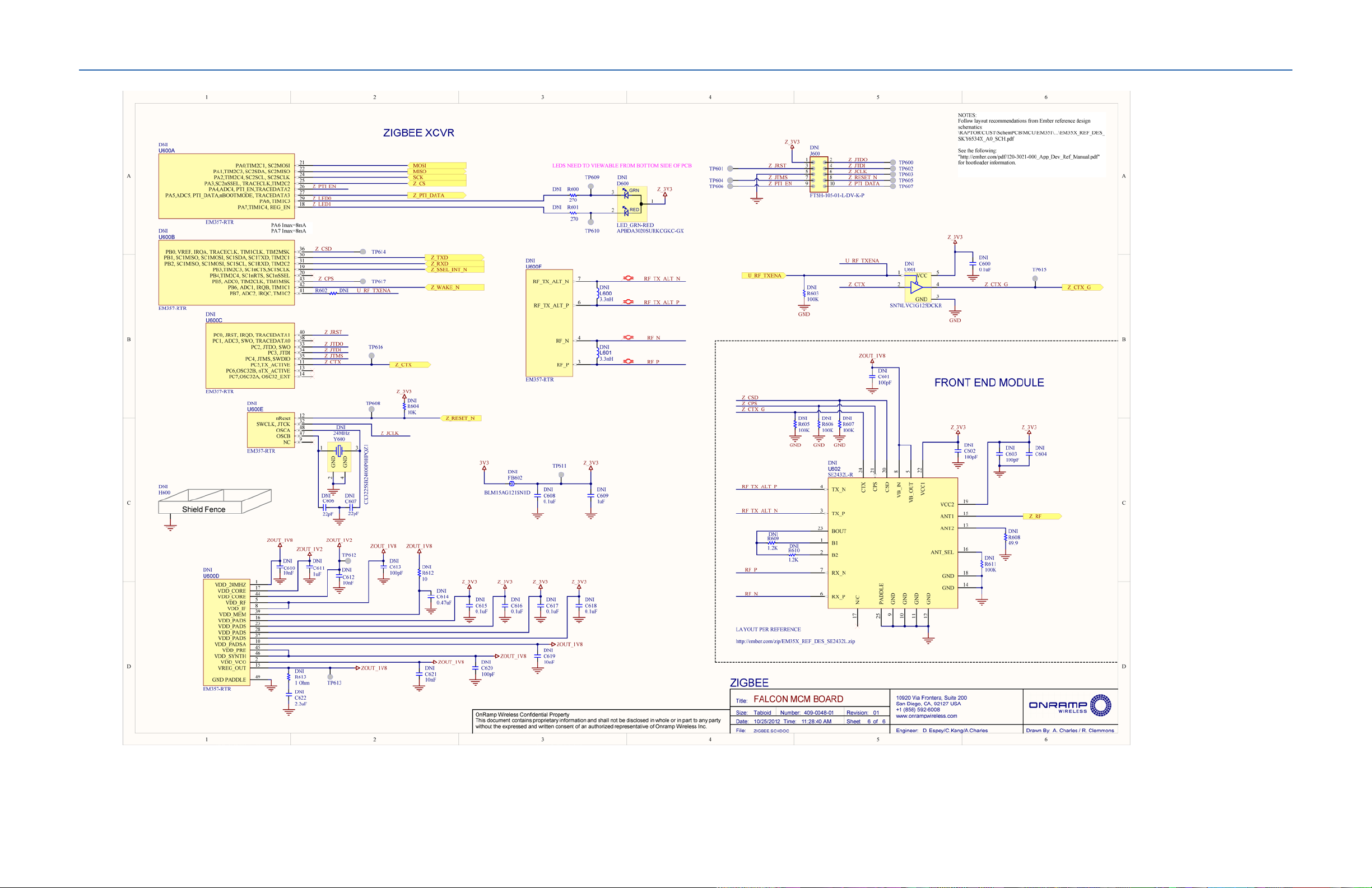
Figure 15. Schematics for TRN-2012 and TRN-2113
On-Ramp Wireless Confidential and Proprietary 33 014-0047-00 Rev. C
Page 40
TRN-2012 / TRN-2113 Integration Specification TRN-2012 / TRN-2113 Mechanical Drawings and Schematics
On-Ramp Wireless Confidential and Proprietary 34 014-0047-00 Rev. C
Page 41
TRN-2012 / TRN-2113 Integration Specification TRN-2012 / TRN-2113 Mechanical Drawings and Schematics
On-Ramp Wireless Confidential and Proprietary 35 014-0047-00 Rev. C
Page 42

TRN-2012 / TRN-2113 Integration Specification TRN-2012 / TRN-2113 Mechanical Drawings and Schematics
On-Ramp Wireless Confidential and Proprietary 36 014-0047-00 Rev. C
Page 43
TRN-2012 / TRN-2113 Integration Specification TRN-2012 / TRN-2113 Mechanical Drawings and Schematics
On-Ramp Wireless Confidential and Proprietary 37 014-0047-00 Rev. C
Page 44
TRN-2012 / TRN-2113 Integration Specification TRN-2012 / TRN-2113 Mechanical Drawings and Schematics
On-Ramp Wireless Confidential and Proprietary 38 014-0047-00 Rev. C
 Loading...