

Page 1

Parque Tecnológico de
Tel (+34) 985 118 859
Fax (+34) 984 283 560
ingeniumsl@ingeniumsl.com
P
Motion sensor
SRKNX
V2.1
ROGRAMMING MANUAL
Asturias, Parcela 50, 33428
Llanera – Asturias - Spain
www.ingeniumsl.com
TECHNICAL DEPARTMENT
Tel (+34) 985 113 339
tecnico@ingeniumsl.com
Page 2

P
ROGRAMMING MANUAL
SRKNX -
V2.1
Index
1 General description ______________________________________________________________ 2
2 Technical information ____________________________________________________________ 3
3 Programming ___________________________________________________________________ 4
3.1 Communication objects ______________________________________________________________ 4
3.2 Objects description _________________________________________________________________ 4
3.3 Parameters ________________________________________________________________________ 6
3.3.1 General parameters _________________________________________________________________________ 6
3.3.2 Channel 1/2 Telegrams ______________________________________________________________________ 8
3.3.3 Channel 1/2 Delays _________________________________________________________________________ 9
4 Recommendations ______________________________________________________________ 11
4.1 Installation _______________________________________________________________________ 11
4.1.1 Positioning _______________________________________________________________________________ 11
4.1.2 Detection side ____________________________________________________________________________ 14
4.2 Supply ___________________________________________________________________________ 14
4.2.1 Supply using an Auxiliary power supply (recommended) __________________________________________ 14
4.2.2 Supply through BUS KNX ____________________________________________________________________ 14
4.3 Advanced configuration _____________________________________________________________ 15
4.3.1 Sensitivity ________________________________________________________________________________ 15
4.3.2 Smoothing and sampling time _______________________________________________________________ 16
4.3.3 Saturation _______________________________________________________________________________ 16
5 Application examples ___________________________________________________________ 17
5.1 Motion switching with double channel ________________________________________________ 17
5.1.1 Devices __________________________________________________________________________________ 17
5.1.2 Description _______________________________________________________________________________ 17
5.1.3 Objects links ______________________________________________________________________________ 17
5.1.4 Parameter settings ________________________________________________________________________ 18
5.2 Master / Slave mode: 1 light and 3 sensors _____________________________________________ 19
5.2.1 Devices __________________________________________________________________________________ 19
5.2.2 Description _______________________________________________________________________________ 19
5.2.3 Objects links ______________________________________________________________________________ 19
5.2.4 Parameter settings ________________________________________________________________________ 20
5.3 Manual on and automatic off ________________________________________________________ 21
5.3.1 Devices __________________________________________________________________________________ 21
5.3.2 Description _______________________________________________________________________________ 21
5.3.3 Objects links ______________________________________________________________________________ 21
5.3.4 Parameter settings ________________________________________________________________________ 22
Motion sensor
1 de 23
Page 3

P
ROGRAMMING MANUAL
SRKNX -
1 G
The SRKNX is a hidden 360º radiofrequency movement detector for installation above false or technical ceilings.
It is also possible to install it in brick walls or plasterboards. This device is oriented to substitute the ceiling 360º
passive detectors, clearly overcoming their performances.
It is based on radio frequency technology, that allows it to pass through any kind of surface, except the metallic
ones. Its hidden installation guarantees safety against non desired intrusions or vandalism. Moreover, it
combines esthetics and automation in a single installation. It allows a wide and easy parameterization, being
suitable for lighting functions, as well as people detection and intruder control.
V2.1
ENER AL DESC RIPT ION
• Detects movement through solid, non-metallic objects (brick, wood, etc).
• Detects minimum movements.
• Hidden installation in false ceilings or walls.
• Easy to install, adds elegance to the lighting design
• It is immune to vandalism.
• Automatic reset after detection.
• Adjustable timer from pulse to 17min.
• Adjustable sensitivity up to 12m.
Motion sensor
2 de 23
Page 4
P
ROGRAMMING MANUAL
SRKNX -
2 T
V2.1
ECH NICA L IN FORM ATIO N
• Supply - 29 Vdc from auxiliary power supply or from KNX BUS.
• Consumption - (depends on source):
o Auxiliary Power Supply 12-30Vdc (Recommended)
35 mA from auxiliary power supply.
1mA from KNX BUS
o KNX BUS (Optional)
35mA from KNX BUS
• Connections - Screw terminal (four poles terminal block).
• Type of protection - IP20. Extra low security voltage SELV, 24V direct current.
• Temperature range - Running: -10ºC a 55ºC / Storage: -30ºC a 60ºC / Transport: -30ºC a 60ºC.
• Size / weight - 25x45x65mm. / 115g.
• Mount - over false ceilings or hidden in walls or bricks.
• Standardization - for KNX.
• Detection range: 12 x 6 m (at 2.5 height).
Motion sensor
3 de 23
Page 5

P
Flags
C R W T U
ROGRAMMING MANUAL
SRKNX -
3 P
Number of communication objects: 11.
Number of assignments: 33.
Object Name / Function Length DPT
V2.1
ROGR AMM ING
3.1 C
0 Channel 1 - Detection event: Bit 1 bit 1.001 ● ● ●
1 Channel 1 - Detection event: Byte 1 byte 5.010 ● ● ●
2 Channel 1 - Detection event: Temperature 2 byte 9.001 ● ● ●
3 Channel 1 - Enable / disable channel 1 bit 1.001 ● ●
OMMUN I CATION OBJECTS
4 Channel 1 - Force remote detection 1 bit 1.001 ● ●
5 Channel 1 - Remaining time (seconds) 2 byte 7.005 ● ● ●
6 Channel 2 - Detection event: Bit 1 bit 1.001 ● ● ●
7 Channel 2 - Detection event: Byte 1 byte 5.010 ● ● ●
8 Channel 2 - Detection event: Temperature 2 byte 9.001 ● ● ●
9 Channel 2 - Enable / disable channel 1 bit 1.001 ● ●
10 Channel 2 - Force remote detection 1 bit 1.001 ● ●
11 Channel 2 - Remaining time (seconds) 2 byte raw ● ● ●
3.2 O
Object 0: Channel 1 - Detection event: Bit
Channel 1 detection communication object in 1 bit format. When a motion is detected and the sensor is
triggered, it sends the correspondent parameter On. When the countdown finishes (switch-off delay) it sends
the correspondent parameter Off.
BJE C T S D ESCRIPTION
Object 1: Channel 1 - Detection event: Byte
Channel 1 detection communication object in 1 byte format. When a motion is detected and the sensor is
triggered, it sends the correspondent parameter On. When the countdown finishes (switch-off delay) it sends
the correspondent parameter Off.
Motion sensor
4 de 23
Page 6

P
ROGRAMMING MANUAL
SRKNX -
V2.1
Object 2: Channel 1 - Detection event: 2 Bytes
Channel 1 detection communication object in 2 bytes format. When a motion is detected and the sensor is
triggered, it sends the correspondent parameter On. When the countdown finishes (switch-off delay) it sends
the correspondent parameter Off.
Object 3: Channel 1 - Enable / disable channel
1 = Motion detection enabled.
0 = Motion detection disabled (stand-by mode).
Object 4: Channel 1 - Force remote detection
1 = Forces a remote detection.
0 = Forces a remote end of detection.
Used for Master-Slave mode. It allows to emulate a detection without any motion. By sending 1, the detector is
activated remotely performing the start detection event. Slave sensors emulate Master detections: link bit
detection event of the slave with
Object 5: Channel 1 - Remaining time (seconds)
0 – 65535 = Remaining time in seconds for end of detection event.
The remaining time of the countdown after motion detection can be read by this communication object.
Object 6: Channel 2 - Detection event: Bit
Channel 2 detection communication object in 1 bit format. When a motion is detected and the sensor is
triggered, it sends the correspondent parameter On. When the countdown finishes (switch-off delay) it sends
the correspondent parameter Off.
Object 7: Channel 2 - Detection event: Byte
Channel 2 detection communication object in 1 byte format. When a motion is detected and the sensor is
triggered, it sends the correspondent parameter On. When the countdown finishes (switch-off delay) it sends
the correspondent parameter Off.
Object 8: Channel 2 - Detection event: 2 Bytes
Channel 2 detection communication object in 2 bytes format. When a motion is detected and the sensor is
triggered, it sends the correspondent parameter On. When the countdown finishes (switch-off delay) it sends
the correspondent parameter Off.
Object 9: Channel 2 - Enable / disable channel
1 = Motion detection enabled.
0 = Motion detection disabled (stand-by mode).
Motion sensor
5 de 23
Page 7

P
ROGRAMMING MANUAL
SRKNX -
Object 10: Channel 2 - Force remote detection
1 = Forces a remote detection.
0 = Forces a remote end of detection.
Used for Master-Slave mode. It allows to emulate a detection without any motion. By sending 1, the detector is
activated remotely performing the start detection event. Slave sensors emulate Master detections: link bit
detection event of the slave with
Object 11: Channel 2 - Remaining time (seconds)
0 – 65535 = Remaining time in seconds for end of detection event. The remaining time of the countdown after
motion detection can be read by this communication object.
V2.1
3.3 P
3.3.1 G
ARA M E T ERS
ENERAL PARAMETERS
General parameters allow to set the detection characteristics of the sensor and are described as follows:
BUSing Address
Values From 0 to 255
Description Not used
Motion sensor
6 de 23
Page 8

P
ROGRAMMING MANUAL
SRKNX -
Advanced: smoothing
V2.1
Values From 0 to 10
Is the value that represents the persistence of the detected movement. This value can range
between 0 and 10. The greater value, the more continuous the movement must be for activation
to occur. This value must be lesser than or equal to half the Sampling time parameter.
Description
Recommended values depending on usage:
− Movement detection (example: activate lighting): 2.
− Intrusion detection: 8.
Sensitivity
Values From 0 to 100
This is the sensitivity percentage value with which the SRBUS detects movements, i.e., it increases
or decreases the detection area. This value can range between 0 and 100%, where 100% is the
maximum sensitivity.
It is not recommended to enter values over 80%, which could make the SRBUS extremely sensitive
Description
to vibrations (in the zone installed) whatever their origin may be.
Recommended values depending on usage:
− Movement detection (example: activate lighting): 40-60% (lower value for smaller rooms).
− Intruder: 20%.
Advanced: sampling time
Values From 0 to 255
This value ranges between 0 and 255, but it is not recommended to be over 64. It represents the
number of samplings taken to evaluate a detection. The greater the value, the slower the device
Description
Advanced: saturation
Values From 0 to 100
Description
response (it is measured in microcontroller cycles, not seconds).
Recommended values depending on usage:
− Movement detection (example: activate lighting): 16.
− Intrusion detection: 64
Is the value that represents the level of movement with which the device is activated,
independently of the Sampling time and Smoothing. If it is not used, it must be set to 100%.
Motion sensor
7 de 23
Page 9

P
ROGRAMMING MANUAL
SRKNX -
V2.1
3.3.2 C
HANNEL
1/2 T
ELEGRAMS
The configuration of the sensor behavior when there is a motion detection and when it finishes is done here.
The working mode and parameterization of both channels is done in the same way and they have similar
parameters that are explained next:
Channel 1 / 2 - Motion bit telegram
Values From 0 to 1
Description
Value sent in object 0/6 (DPT1.00X) when a motion is detected.
Channel 1 / 2 - No motion bit telegram
Values From 0 to 1
Description
Value sent in object 0/6 (DPT1.00X) after switch-off delay.
Channel 1 / 2 - Motion temperature telegram
Values From -1000 to 1000 ºC
Description
Channel 1 / 2 - No motion temperature telegram
Values From -1000 to 1000 ºC
Description
Value sent in object 2/8 (DPT9.002) when a motion is detected.
Value sent in object 2/8 (DPT9.002) after switch-off delay.
Motion sensor
8 de 23
Page 10

P
ROGRAMMING MANUAL
SRKNX -
Channel 1 / 2 - Motion byte telegram
Values From 0 to 255
Description
Channel 1 / 2 - No motion byte telegram
Values From 0 to 255
Description
V2.1
Value sent in object 1/7 (Byte) when a motion is detected.
Value sent in object 1/7 (Byte) after switch-off delay.
Channel 1 / 2 - Telegrams when motion detection
Values Yes / No
Description
If this parameter is enabled, after a motion detection, the sensor sends ON telegrams in objects
0,1,2 for channel 1 and objects 6,7,8 for channel 2.
Channel 1 / 2 - Telegrams after motion detection
Values Yes / No
Description
If this parameter is enabled, if there is no motion within the switch-off delay, the sensor sends OFF
telegrams in objects 0,1,2 for channel 1 and objects 6,7,8 for channel 2.
Channel 1 / 2 - Off telegrams when channel disable
Values Yes / No
Description
If this parameter is enabled, after a channel is switched off with objects 3 or 9, the OFF events are
sent by objects 0,1,2 for channel 1 and objects 6,7,8 for channel 2.
3.3.3 C
HANNEL
1/2 D
ELAYS
Motion sensor
9 de 23
Page 11

P
ROGRAMMING MANUAL
SRKNX -
V2.1
These parameters allow to configure time delays when enabling or disabling the sensor and the time that the
light is on when the sensor is programmed for lightning control.
Channel disable delay
Values From 0 to 65535
Description
Channel enable delay
The channel keeps detecting motion until the disable delay time set has elapsed.
Values From 0 to 65535
Description
Channel switch-off delay
The channel does not respond until the enable delay time set has elapsed.
Values From 0 to 65535
This parameter is the time between the last motion detection and the sending of switch-off
events. In lightning control, the switch-off delay determines how long after a motion is detected
Description
the light is to be switched off again. With every motion, the sensor is retriggered and the
countdown is re-started, so the light is not switched off until there is no motion within the delay
time
Motion sensor
10 de 23
Page 12

P
ROGRAMMING MANUAL
SRKNX -
4 R
The SRKNX could be installed in a false ceiling or behind walls of any non-metalic material. Its hidden installation
ensure safety unwanted intrusions or vandalism to not be accessible.
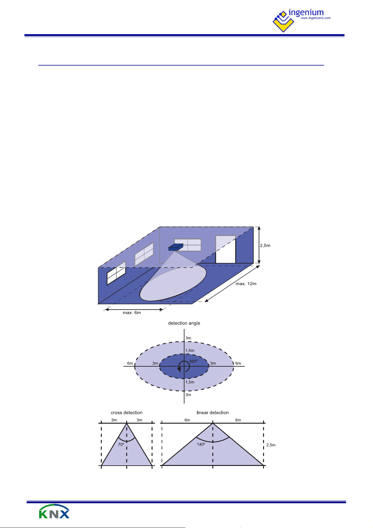
For longitudinal places like corridors, it is important to place the SRKNX in the correct position. The correct
solution is to place it lengthwise, with the length of the device parallel to the length of the room. Next image
shows the detection directions and the area detection on each one, estimated for place the SRKNX at 2.5m from
the floor.
V2.1
ECO MMEN DATI ONS
4.1 I
NST ALLATION
4.1.1 P
OSITIONING
The detection area (placing the SRKNX at 2.5m from the floor) is:
• Guaranteed: 6x3 m.
• Maximum: 12x6m.
These values could change if the SRKNX positioning height changes. The beam detection angle is 140º in
longitudinal direction and 70º in transversal direction.
Motion sensor
11 de 23
Page 13

P
ROGRAMMING MANUAL
SRKNX -
V2.1
The best position of the sensor depends on the shape of the room where it is installed, for example a meeting
room with long shape:
The first positioning may cause problems with false detections outside the meeting room or non-detections in
some areas of the room.
The second positioning is the best because the detection area of the sensors fits better with the shape of the
room.
Motion sensor
12 de 23
Page 14

P
ROGRAMMING MANUAL
SRKNX -
V2.1
The SRKNX can be partially blinded with metal tape to cancel detection in a zone/direction. For example, when it
has to be installed in one side of the room, it is recommended to reduce the detection area with metal tape in
order to avoid false detections by movements behind the wall.
In addition, the SRKNX must be firm fixed to the surface it will be installed on to avoid false detections and also it
is very important no to install the device in locations susceptible to vibrations or over fluorescents lights for
example.
Motion sensor
13 de 23
Page 15

P
ROGRAMMING MANUAL
SRKNX -
The SRKNX detects by the silk screened side, so it should be placed with this side faced to the movement.
For example, when using the sensor in ceilings, if it is installed with the wrong side faced to the room area it
won’t detect anything or it can detect movements in the upper floor.
It is possible to choose between two different options to supply the SRKNX: using an auxiliary power supply
(recommended) or through BUS KNX.
V2.1
4.1.2 D
4.2 S
ETECTION SIDE
UPPLY
4.2.1 S
The consumption for this option is 30 mA from the auxiliary power supply (12-30Vdc) and 1 mA from the BUS
KNX.
To supply the SRKNX device using an auxiliary power supply, instead of the KNX BUS, the wiring connection
should be:
4.2.2 S
The consumption for this option is 30 mA from the BUS KNX.
To supply the SRKNX device through BUS KNX, the wiring connection should be:
UPPLY USING AN AUXILIARY POWER SUPPLY (RECOMMENDED
UPPLY THROUGH
BUS KNX
)
Motion sensor
14 de 23
Page 16

P
ROGRAMMING MANUAL
SRKNX -
The SRKNX emits a detection beam of high intensity, being of greater or lesser scope depending on the
sensitivity for which it has been programmed from ETS parameters. When the sensitivity is 100%, the detection
range of the sensor covers an area of 12 x 6 m approximately at 2.5 height. If we reduce the sensitivity we will
reduce the detection range proportionally so this parameter must be configured accorded to the size of the
room or area that should be covered.
In the next figure is shown what is the SRKNX behavior depending on the advanced parameters configured:
V2.1
4.3 A
4.3.1 S
DVAN CED CONFIGURATION
ENSITIVITY
Motion sensor
15 de 23
Page 17

P
ROGRAMMING MANUAL
SRKNX -
The SRKNX is constantly emitting radio frequency signals. The movement detection is based on the change that
any body, material or thing makes in the radio signals reflected. These signals are filtered, processed and
considered as a “motion detection” depending on parameters.
Any movement that generates a number of pulses higher than the smoothing, within a given sampling time, is
considered a “motion detection” by the sensor. For the same sampling time, increasing the smoothing means
that the movement should be faster and higher to generate a “motion detection” because more pulses are
necessary.
The telegrams executed by the sensor when there is a motion detection are sent after every sampling time, so
increasing the sampling time makes the sensor response slower. If the smoothing does not change, the
movement needed to generate a “motion detection” can be the same, but the sensor does not switch on the
light after the sampling time.
V2.1
4.3.2 S
4.3.3 S
MOOTHING AND SAMPLING TIME
ATURATION
The saturation is the level of reflected signal with which the device considers a “motion detection”,
independently of the sampling time and smoothing. This means that, for a given sampling time and smoothing, if
the signal level received by the sensor is higher than the saturation, it generates a “motion detection” even if
there was not any movement.
Motion sensor
16 de 23
Page 18

P
Object 0
Object 4
Object 6
Object 6
ROGRAMMING MANUAL
SRKNX -
5 A
SRKNX: Motion double channel sensor.
6E4S-KNX: On/Off actuator with 6 digital inputs and 4 digital outputs.
Light number 1 and number 2 are connected to outputs 1 and 2 (Z1 and Z2) of the 6E4S-KNX actuator.
V2.1
PPL ICAT ION EXAM PLES
5.1 M
5.1.1 D
5.1.2 D
OTIO N SWITCHING WITH D O U BLE CHANNEL
EVICES
ESCRIPTION
The SRKNX controls the lights by motion detection. Light number 1 will be controlled by the firs channel of the
sensor and will be switched on for 15 seconds and the Light number 2 will be controlled by the second channel
and will be switched on for 20 seconds.
5.1.3 O
SRKNX – Object 0 -> Object 4 – 6E4S-KNX
SRKNX – Object 6 -> Object 6 – 6E4S-KNX
BJECTS LINKS
Motion sensor
17 de 23
Page 19

P
ROGRAMMING MANUAL
SRKNX -
V2.1
5.1.4 P
ARAMETER SETTINGS
The following parameter setting is generally recommended for this example. The ideal parameters may change
depending on the application or installation.
Parameter name Recommended setting
General parameters Smoothing 2
Sensitivity 30
Sampling time 16
Saturation 100
Ch1 Event values Bit event on 1
Bit event off 0
Detection event notification yes
End of detection event notification yes
Ch1 Delays Channel enable delay 0
Channel disable delay 0
Switch-off delay 15
Ch2 Event values Bit event on 1
Bit event off 0
Detection event notification yes
End of detection event notification yes
Ch2 Delays Channel enable delay 0
Channel disable delay 0
Switch-off delay 20
A Smoothing = 2 and Sampling time = 16 are generally recommended for normal lightning control by motion
detection. The sensitivity depends on the detection area desired so it must be configured according to the area
that should be covered. About the Saturation function, if it is not used it should have a value of 100. See 4.3
Advanced configuration for further information.
Motion sensor
18 de 23
Page 20

P
Slave 1
Slave 2
Object 0
Object 0
Object 4
Object 4
Object 0
Master
ROGRAMMING MANUAL
SRKNX -
3 x SRKNX: Motion double channel sensor.
6E4S-KNX: On/Off actuator with 6 digital inputs and 4 digital outputs.
A circuit is connected to output 1 (Z1) of the 6E6S-KNX actuator and lights are placed along a corridor. Three
SRKNX sensors, one in the middle and another two placed on each side of the corridor will control the lights by
motion detection. The lights will be switched on for 15 seconds.
V2.1
5.2 M
5.2.1 D
5.2.2 D
AST E R / SLAVE M O D E: 1 LIG H T A ND 3 SE NS ORS
EVICES
ESCRIPTION
5.2.3 O
Slave 1 SRKNX – Object 0 -> Object 4 – Master SRKNX
Slave 2 SRKNX – Object 0 -> Object 4 – Master SRKNX
Master SRKNX – Object 0 -> Object 4 – 6E4S-KNX
BJECTS LINKS
Motion sensor
19 de 23
Page 21

P
ROGRAMMING MANUAL
SRKNX -
V2.1
5.2.4 P
ARAMETER SETTINGS
The following parameter setting is generally recommended for this example. The ideal parameters may change
depending on the application or installation.
Parameter name Recommended setting
Master / Slave Smoothing 2
General Parameters Sensitivity 30
Sampling time 16
Saturation 100
Master Ch1 Bit event on 1
Event values Bit event off 0
Detection event notification yes
End of detection event notification yes
Master Ch1 Channel enable delay 0
Delays Channel disable delay 0
Switch-off delay 15
Slave 1 Ch1 Bit event on 1
Event values Bit event off 0
Detection event notification yes
End of detection event notification yes
Slave 1 Ch1 Channel enable delay 0
Delays Channel disable delay 0
Switch-off delay 5
Slave 2 Ch1 Bit event on 1
Event values Bit event off 0
Detection event notification yes
End of detection event notification yes
Slave 2 Ch1 Channel enable delay 0
Delays Channel disable delay 0
Switch-off delay 5
A Smoothing = 2 and Sampling time = 16 are generally recommended for normal lightning control by motion
detection. The sensitivity depends on the detection area desired so it must be configured according to the area
that should be covered. About the Saturation function, if it is not used it should have a value of 100. See 4.3
Advanced configuration for further information.
The switch-off delay of the master is the time that the light is on. The switch-off delay of the slaves should be
less in order to send their detections quickly to the master. If there is a huge amount of telegrams in the bus
because of the slaves, their sampling times and switch-off delays can be increased.
Motion sensor
20 de 23
Page 22

P
Object 0
Object 4
Input 1
Object X
ROGRAMMING MANUAL
SRKNX -
SRKNX: Motion double channel sensor.
6E4S-KNX: On/Off actuator with 6 digital inputs and 4 digital outputs.
KNX Pushbutton.
This function is useful in lobbys, meeting rooms, waiting rooms, etc. If the room is occupied for only a short time
no light is required but when the light is switched on it must be guaranteed to switch off when the room is left.
The light of the room is connected to the output 1 (Z1) of the 6E4S-KNX actuator and it should be switched on
manually as required with the input of the device (I1) or any other KNX pushbutton.
V2.1
5.3 M
5.3.1 D
5.3.2 D
ANU A L ON AND AUTOMATIC O FF
EVICES
ESCRIPTION
The SRKNX controls the lights by motion detection but its sole purpose is to switch off the light after 30 seconds
with no movement in the room.
5.3.3 O
SRKNX – Object 0 -> Object 4 – 6E4S-KNX
KNX Pushbutton – Object X -> Object 4 – 6E4S-KNX
BJECTS LINKS
Motion sensor
(internal link)
21 de 23
Page 23

P
ROGRAMMING MANUAL
SRKNX -
V2.1
5.3.4 P
ARAMETER SETTINGS
The following parameter setting is generally recommended for this example. The ideal parameters may change
depending on the application or installation.
Parameter name Recommended setting
General parameters Smoothing 2
Sensitivity 30
Sampling time 16
Saturation 100
Ch1 Event values Bit event off 0
Detection event notification No
End of detection event notification yes
Ch1 Delays Channel enable delay 0
Channel disable delay 0
Switch-off delay 30
A Smoothing = 2 and Sampling time = 16 are generally recommended for normal lightning control by motion
detection. The sensitivity depends on the detection area desired so it must be configured according to the area
that should be covered. About the Saturation function, if it is not used it should have a value of 100. See 4.3
Advanced configuration for further information.
The detection event notification should be disabled because we do not want the sensor to do anything when
motion is detected; we only want to switch of the light after 30 seconds without any movement in the room.
Motion sensor
22 de 23
Page 24

Parque Tecnológico de Asturias, Parcela 50,
33428 Llanera – Asturias - Spain
Tel (+34) 985 118 859
Fax (+34) 984 283 560
ingeniumsl@ingeniumsl.com
www.ingeniumsl.com
 Loading...