

Page 1

Gateway
BUSing-MDAC-D
Programming manual
V1.0
Page 2
PROGRAMMING MANUAL
BUSING-MDAC-DV1.0
Gateway
2Of17
Index
1 General description ____________________________________________________________ 3
2 Technical description __________________________________________________________ 4
3 Programming of the device _____________________________________________________ 5
3.1 Point to point control in PPL________________________________________________________6
4 Table of Compatibility __________________________________________________________ 9
4.1 Indoor units _____________________________________________________________________9
4.2 Outdoor units _________________________________________________________________ 13
5 Records that supports _________________________________________________________ 14
5.1 RAM _________________________________________________________________________ 14
5.2 EEPROM ______________________________________________________________________ 14
6 Data downloading ___________________________________________________________ 15
7 Wiring _____________________________________________________________________ 16
Page 3
PROGRAMMING MANUAL
BUSING-MDAC-DV1.0
Gateway
3Of17
1 GENERAL DESCRIPTION
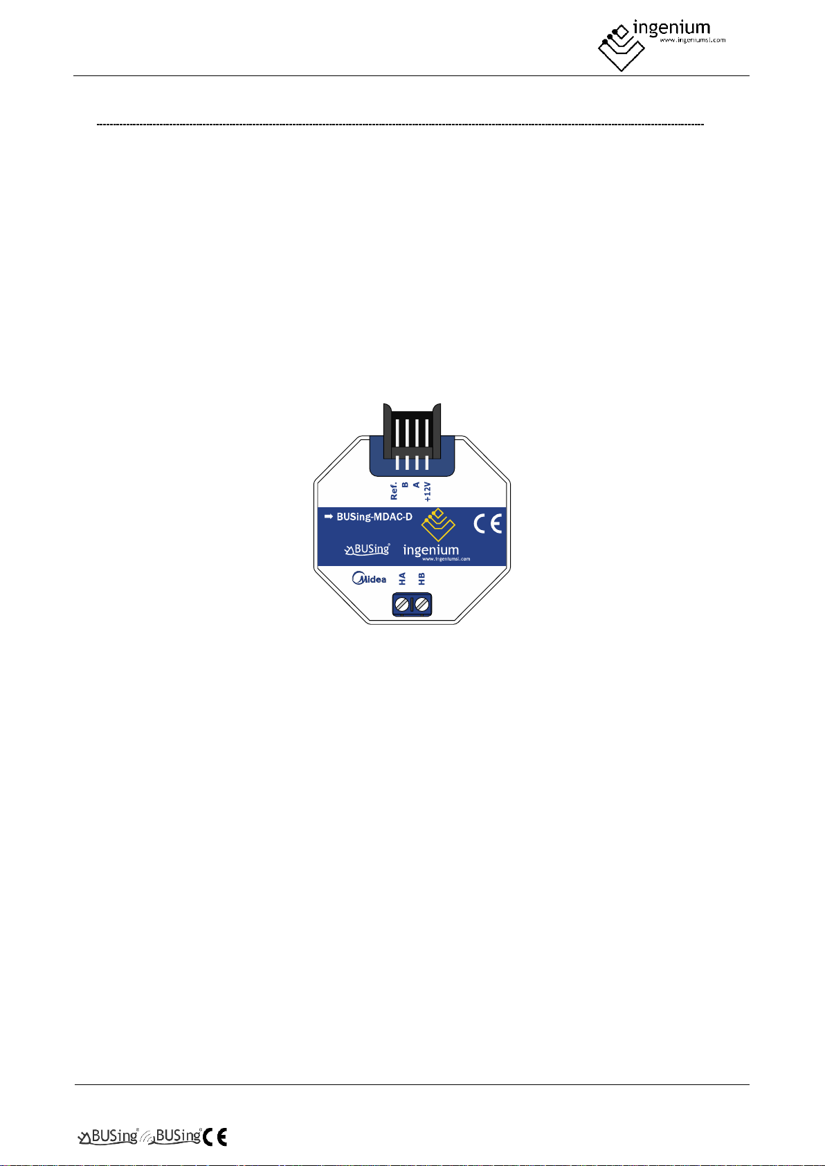
The BUSing-MDAC-D gateway allows direct communication from a BUSing® protocol installation with
compatible Midea® climate units. This makes it easy to control the machine from BUSing screens, web servers
or the Ingenium app available for mobile devices (iOS and Android) with a fully graphical and visual interface.
Apart from reading ambient temperature, set point temperature may be consulted and modified, as well as
indicating to the machine its mode of operation and fan speed.
Each gateway will allow the control of an internal Midea® climate unit, to which it is connected directly through
a connector supplied with the gateway, to the internal unit S21 connection. The maximum cable distance
between machine and gateway must be 1 m.
To ensure compatibility of the gateways, contact the technical service or consult the compatibility table.
Page 4
PROGRAMMING MANUAL
BUSING-MDAC-DV1.0
Gateway
4Of17
2 TECHNICAL DESCRIPTION
• Gateway for integration of Midea AC air conditioning system and BUSing® protocol.
• Allows control of one indoor Midea unit (check compatibility table)
• Direct communication through 2 wires with no polarity, to HA and HB terminals from indoor unit.
• Control and monitoring of the status and operating modes of the Midea climate machine.
o On/Off machine
o Ambient temperature
o Consignment temperature
o Modes of operation
o Machine speed
• Mounting next to the climate unit or integrated into the ceiling.
• Does not support master/slave due to it works either with Midea remote control connected or not,
being the last order received priority.
• It allows control from BUSing® screens, web servers or the free Ingenium App.
Page 5
PROGRAMMING MANUAL
BUSING-MDAC-DV1.0
Gateway
5Of17
3 PROGRAMMING OF THE DEVICE
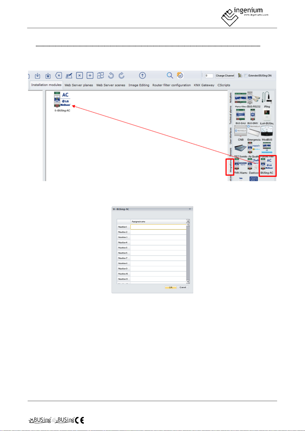
From the Development System (SIDE) BUSing-AC node must be inserted in the integrations tab, in the address
wanted the gateway to have.
By double-clicking or right-clicking on the icon, and accessing its properties, a window will open like the
following:
The only thing that needs to be programmed in this part, is to name the machine 1, which will be the one
appearing, when linking it, on the graphical interfaces. The rest of the machines will not be used, as this
gateway can only control one climate unit.
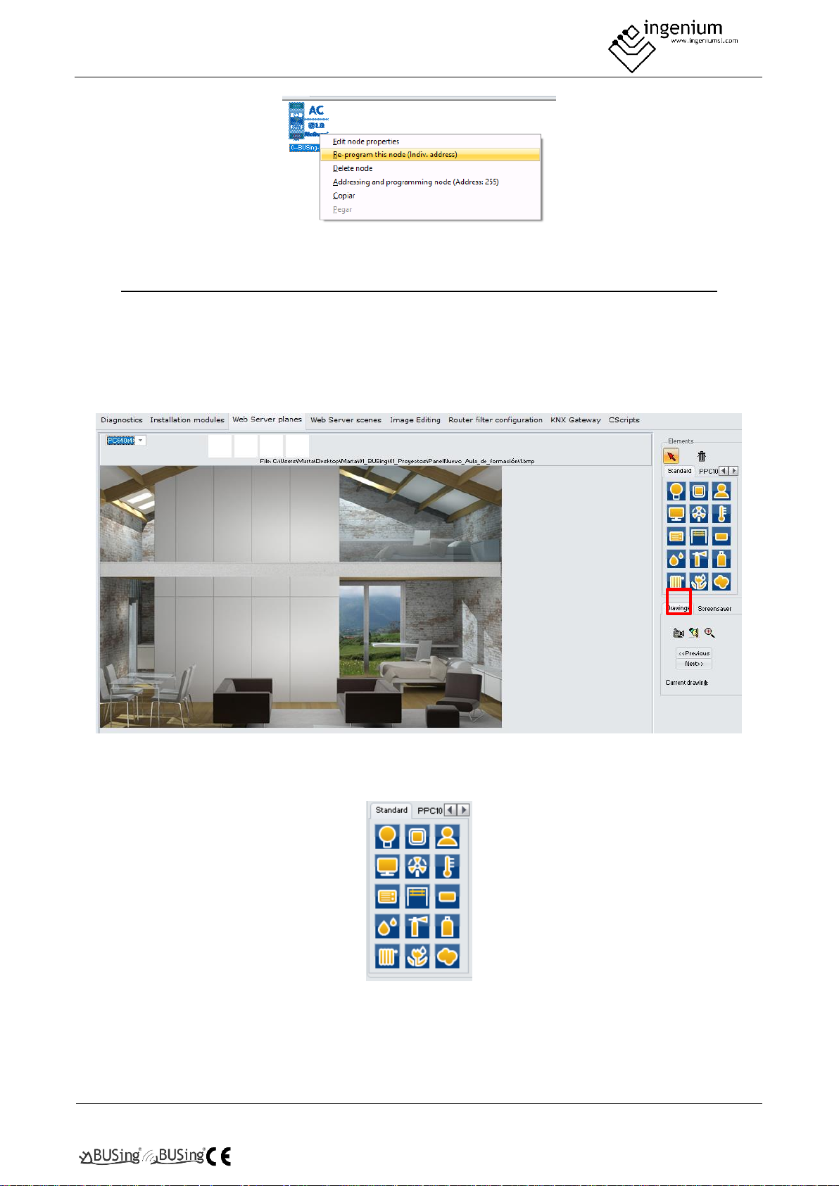
Once entered in the BUSing project and having only connected to the BUS this computer, the device should
be addressed, right click on it and select Program this node by appearing the property screen on which you
must click on programming. You can also right-click: Direct and program node.
Page 6
PROGRAMMING MANUAL
BUSING-MDAC-DV1.0
Gateway
6Of17
3.1 POINT TO POINT CONTROL IN PPL
To be able to control the machine it will be necessary to include a thermostat icon on one of the graphical
interfaces or web server of BUSing®, and make a point-to-point link. The following example is about Ethbus3
or PPL.
In the Web Server Planes tab, with a previously added plane, through the red icon, located on the right side:
Click on a thermometer icon, available in the icon battery on the right. Next, with the mouse you click on the
part of the plane you want to incorporate this icon:
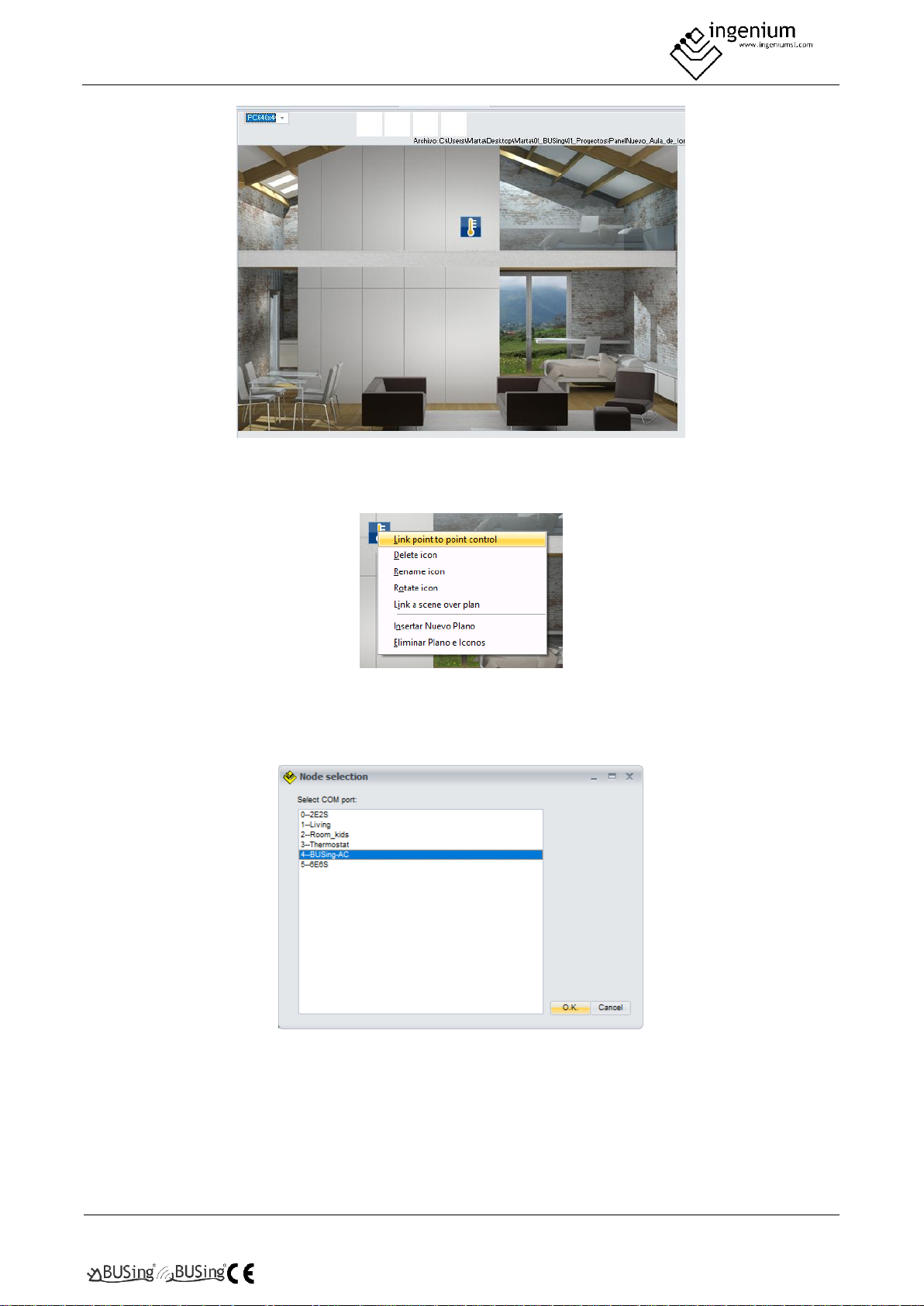
And the map would look like:
Page 7
PROGRAMMING MANUAL
BUSING-MDAC-DV1.0
Gateway
7Of17
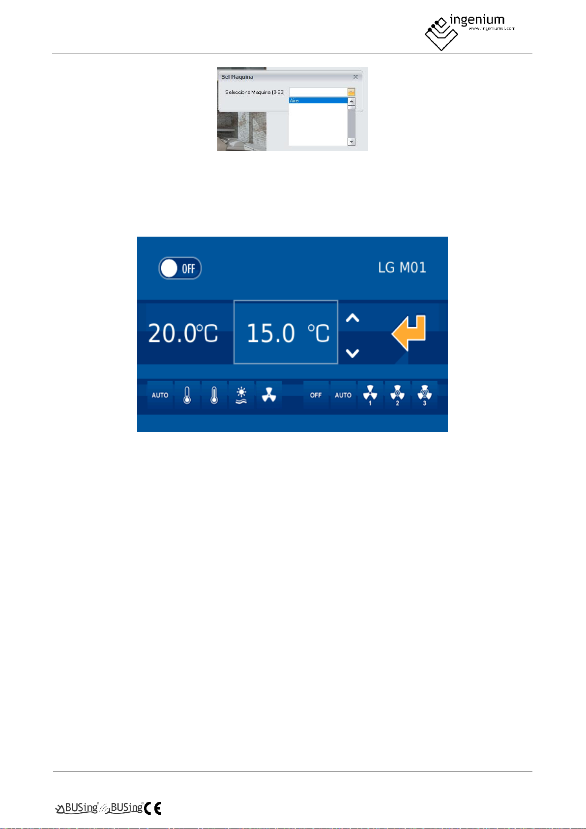
The next step will be to make a point-to-point link of the thermostat icon with the AC gateway. To do this, you
must right click on the icon and select the option Link control point-to-point.
When clicking on this option, a window will appear like the next one, with all the nodes added to our project
(in Installation Modules). Select the corresponding node for AC gateway, in the case of the example, node 4
and press Ok.
Again, a window will appear to select the Midea machine to add. It is reminded that this gateway only controls
1 indoor climate unit, so only the first machine should be selected, though 0 to 63 machines are available. This
is because that BUSing-AC icon added in Installation Modules serves to program other BUSing AC gateways
that can control more than one AC unit.
Page 8
PROGRAMMING MANUAL
BUSING-MDAC-DV1.0
Gateway
8Of17
Once pressed Ok, the point-to-point control of the gateway would already be linked with its corresponding
icon on the PPL. For further information regarding programming a PPL, check its programming manual.
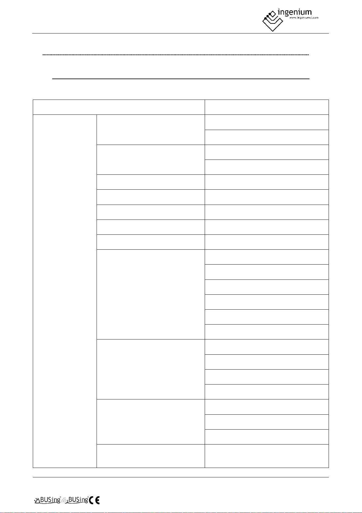
Once downloaded the programming to the screen or webserver, the graphic interface for this device would
look like the following:
On the left side, the ambient temperature can be read, the next value in the rectangle is the setpoint
temperature. Finally, at the left bottom are the available modes of the AC unit, and on the right side the speed.
Page 9
PROGRAMMING MANUAL
BUSING-MDAC-DV1.0
Gateway
9Of17
4 TABLE OF COMPATIBILITY
4.1 INDOOR UNITS
Compatible models always refer to indoor units, not references to outdoor plus indoor units.
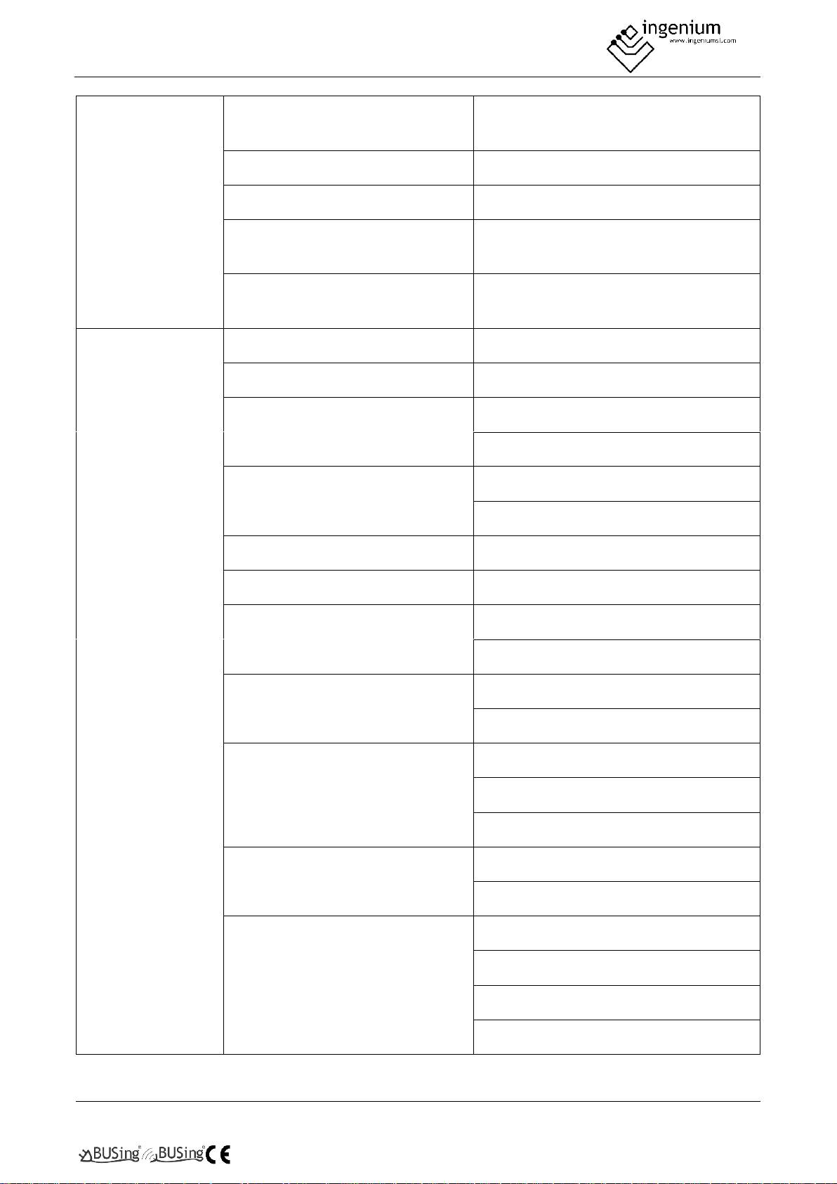
Indoor unit type
Reference
Casettes
One-way casette
MDV-DxxQ1/N1-C
MDV-DxxQ1/N1-D
One-way casette VRF
MDV-DxxQ1/N1-D
MDV-DxxQ1/N1
Two-way cassette
MDV-DxxQ2/N1
Compact four-way casette
MDV-DxxQ4/N1-A3
Four-way casette
MDV-DxxQ4/N1-D
ART FLUX 360º casette (600x600)
MI-xxQ4/DHN1-A3
ART FLUX 360º ) casette
MI-xxQ4/DHN1-D
Compact (600x600) Multi
MCA3I-xxHRFNx-QRD0
MCA3U-xxHRFNx-QRD0W
MCA3I-xxFNXD0
MCA3I-xxHRFN1-QRC8
MCA3U-xxHRFN1-QRD0W
MCA3-xxHRFN1-QRC8W(B)
Super Slim (840x840)
MCD-xxFNXD0
MCD-xxHRFNx-QRD0
MCD-xxHRFN1-QRC8W(D)
MCD-xxHRFN1-QRD0
Cassette 600x600
MCA3U-xxHRFNx-QRD0W
MCA3U-xxHRFN1-QRD0W
MCA3-xxHRFN1-QRD0
Cassette 600x600 2 PIPES / PANEL
INCLUDED
MKD-Vxx
Page 10
PROGRAMMING MANUAL
BUSING-MDAC-DV1.0
Gateway
10Of17
Cassette 600x600 4 PIPES / PANEL
INCLUDED
MKD-Vxxf
Cassette VRF 600x600
MI-xxQ4/DHN1-A3
Cassette VRF 840x840
MI-xxQ4/DHN1-D
Cassette 840x840 2 PIPES / PANEL
INCLUDED
VxxR
Cassette 840x840 4 PIPES / PANEL
INCLUDED
VxxF
Ducted
T1, High Static Pressure
MDV-DxxT1/N1-B
T2, Medium Static Pressure
MDV-DxxT2/N1-DA5
T3, Low Static Pressure
MDV-DxxT3/N1-B
MDV-DxxT3/N1-C
Slim A5 medium static duct
MDV-DxxT2/N1-DA5
MDV-DxxT2/N1-CA5
A5 medium static duct
MDV-DxxT2/N1-BA5
MIV V4+ medium static duct
MVMxxA-VA1
High static duct
MDV-DxxT1/N1-B
MDV-DxxT1/N1
High static duct (Inverter Fan)
MI-xxT1/DHN1-B
MI-xxT2/DHN1-DA5
Multi
MTBI-xxHWFN1-QRD0
MTB-xxHWFN1-QRC8W(B)
MTB-xxHWFN1-QRC8W(D)
A5
MTBU-xxQRD0W
MTBU-xxHWFN1-QRD0
A6
MTIU-xxHWFNx-QRD0W(V1)
MTIU-xxHWFNx-QRD0W
MTI-xxHWFNx-QRD0(V1)
MTI-xxHWFNx-QRD0
Page 11
PROGRAMMING MANUAL
BUSING-MDAC-DV1.0
Gateway
11Of17
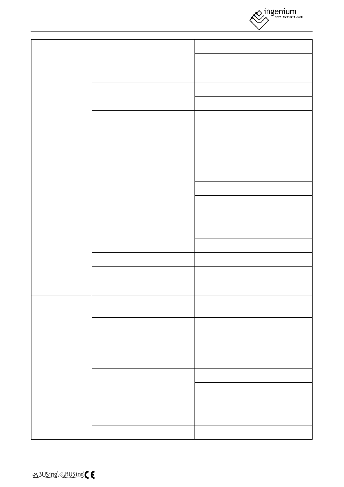
MTI-xxFNXD0
MTI-xxHWFN1-QRD0
MTIU-xxFNXD0
VRF
MI-xxT2/DHN1-DA5
MI-xxT2/DHN1-BA5
High Pressure DC
High capacity VRF
MI-xxT1/DHN1-B
FCU/AHU
FCU/AHU 1
AHUKZ-xx
AHUKZ-xxB
Ceiling / floor
Ceiling / floor
MUEU-xxHRFNx-QRD0W
MUE-xxHRFNx-QRD0
MDV-DxxDL/N1-C
MI-xxDL/DHN1-C
MUE-xxFNXD0
MUE-xxHRFN1-QRD0
Ceiling / floor VRF
MI-xxDL/DHN1-C
Floor with / without envelope VRF
MI-DxxZ/N1-F4
MDV-DxxZ/N1-F4
Floor stand type
Exposed type floor standing with side
air return
MDV-DxxZ/N1-F4
Exposed type floor standing with
bottom air return
MDV-DxxZ/N1-F5
Concealed type floor standing
MDV-DxxZ/N1-F3B
Wall-mounted unit
R3 series wall-mounted
MDV-DxxG-R3/N1Y
C series wall-mounted
MDV-DxxG/DN1YB
MDV-DxxG/N1YB
S series wall-mounted
MDV-DxxG/N1-S
MDV-DxxG/DN1-S
Wall-Mounted
MI-xxG/DHN1-M
Page 12
PROGRAMMING MANUAL
BUSING-MDAC-DV1.0
Gateway
12Of17
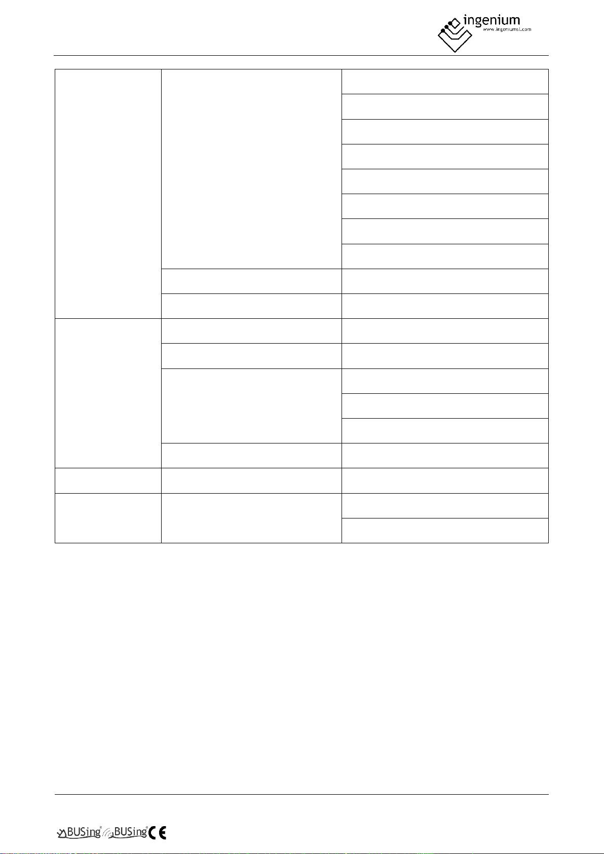
Mural
MSAGDU-xxHRFN8-QRD0GW (2)
MSAGCU-xxHRFNx-QRD0GW (2)
MSAGBU-xxHRFN8-QRD1GW(GA) (2)
MSAGDU-xxHRFNx-QRD0GW (2)
MSMBAU-xxHRFN1-QRD0GW(B)2
MSMBBU-xxHRFN1-QRD0GW(B)2
MSMBCU-xxHRFN1-QRD0GW(B)2
MSMBDU-xxHRFN1-QRD0GW(B)2
FAN COILS DC VRF
VxxB
VRF
MI-xxG/DHN1-M
Console
Console
MDV-DxxZ/DN1-B
Console with/without casing
MI-DxxZ/N1-F4
Console double flow multi
MFAI-xxHRFN1-QRC8
MFAU-xxHRFN1-QRD0
MFA-xxHRFN1-QRC8W
VRF
MDV-DxxZ/DN1-B
Fresh air unit
Fresh air unit
MDV-DxxT1/N1-FA
Column
TYPE N
MFM-xxHRFN1-QRD0
MFM-xxARFN1-RRD0
1
In order to use AHU units, it is necessary to connect BUSing Gateway to XYE bus of outdoor unit instead of
indoor unit bus.
2
This unit requires a multifunction board (contact the supplier).
XX specifies the indoor unit power
(01/02/03/07/09/12/14/15/18/22/24/28/30/36/45/54/56/60/71/72/80/90/100/112/125/140/160/200/250
/280/300/400/450/500/560/600/750/950/1200/1500)
All units including XYE connector and compatible with centralized controller MD-CCM03…09/E will be
compatibles with BUSing-MDAC-D gateway.
Any air conditioning model which is not on the list might not be compatible with the Gateway.
Ingenium cannot guarantee that this document has no writing or composition errors, as well as
similar problems.
Page 13
PROGRAMMING MANUAL
BUSING-MDAC-DV1.0
Gateway
13Of17
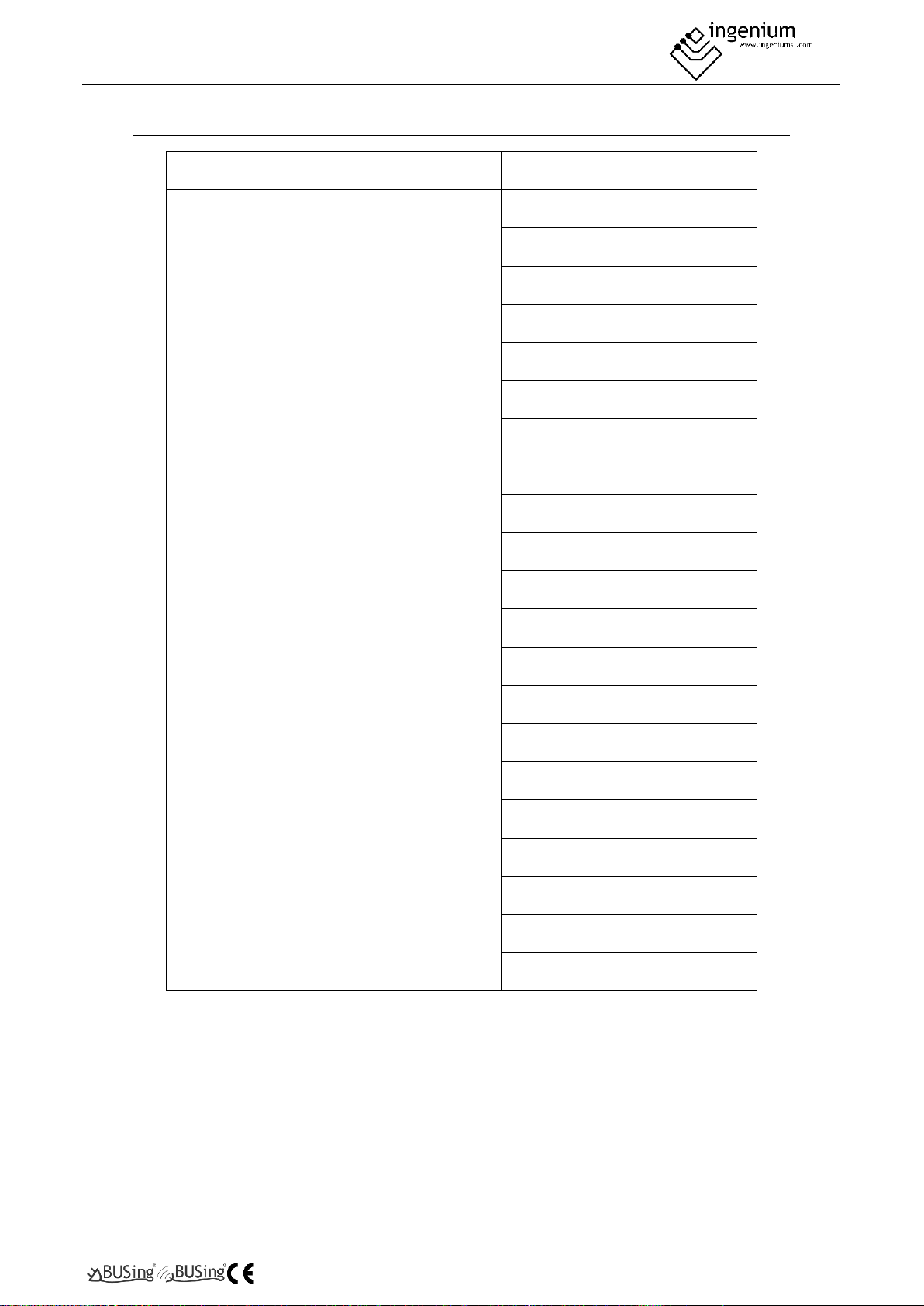
4.2 OUTDOOR UNITS
Outdoor units type
Reference
EXCELLENCE VRF
MDV-VxxxW/DN1
MDV-VxxxW/DN1(B)
MDV-VxxxW/DRN1
MDV-VxxxW/DRN1(A)
MDV-xxxW/DRN1-i(B)
MDV-xxxW/DRN1-i(C)
MV5-ExxxW/V2GN1
MV5-XxxxW/V2GN1
MDVS-xxx(8)W/DRN1
MDVS-xxx(10)W/DRN1
MDVS-xxx(12)W/DRN1
MDV-xxx(8)W/D2RN1T(C)
MDV-xxx(10)W/D2RN1T(C)
MDV-xx(12)W/D2RN1T(C)
MDV-xxx(14)W/D2RN1T(C)
MDV-xxx(16)W/D2RN1T(C)
MV-xxx(8)W/D2RN1T(D)
MV-xxx(10)W/D2RN1T(D)
MV-xxx(12)W/D2RN1T(D)
MV-xxx(14)W/D2RN1T(D)
MV-xxx(16)W/D2RN1T(D)
Any air conditioning model which is not on the list might not be compatible with the Gateway.
All units including XYE connector and compatible with centralized controller MD-CCM03…09/E will be
compatibles with BUSing-MDAC-D gateway.
Page 14
PROGRAMMING MANUAL
BUSING-MDAC-DV1.0
Gateway
14Of17
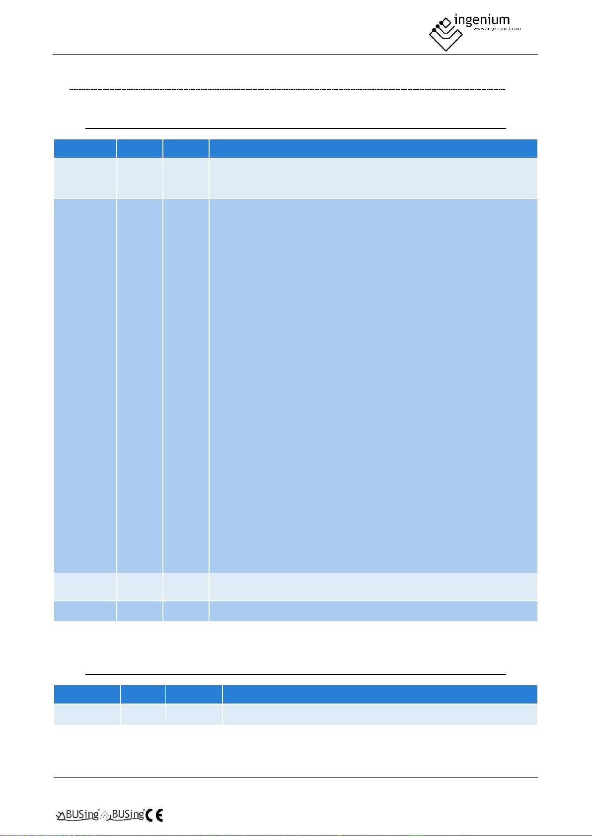
5 RECORDS THAT SUPPORTS
5.1 RAM
Command
Data 1
Data 2
Description
Read/
Write
0
0-3
0 = Deactivate control of the machine.
3 = On machine.
2 = Off machine.
Read/
Write
1
0-68
Ventilation speed and operating mode.
Data 2 = 0-4: Fan off.
Data 2 = 16: Low ventilation (Low)/Cold mode (Cool).
Data 2 = 17: Low ventilation (Low)/Dry mode.
Data 2 = 18: Low ventilation (Low)/Ventilation-only mode (Fan).
Data 2 = 19: Low ventilation (Low)/Auto mode.
Data 2 = 20: Low ventilation (Low)/Heat mode.
Data 2 = 32: Medium ventilation (Medium)/Cold mode (Cool).
Data 2 = 33: Medium ventilation (Medium)/Dry mode.
Data 2 = 34: Medium ventilation (Medium)/Ventilation-only mode
(Fan).
Data 2 = 35: Medium ventilation/automatic mode (Auto).
Data 2 = 36: Medium ventilation (Medium)/Heat mode.
Data 2 = 48: High ventilation (High)/Cold mode (Cool).
Data 2 = 49: High ventilation (High)/Dry mode.
Data 2 = 50: High ventilation (High)/Ventilation-only mode (Fan).
Data 2 = 51: High ventilation (High)/Auto mode.
Data 2 = 52: High ventilation (High)/Heat mode.
Data 2 = 64: Automatic ventilation (Auto)/Cold mode (Cool).
Data 2 = 65: Automatic ventilation (Auto)/Dry mode.
Data 2 = 66: Automatic ventilation (Auto)/Ventilation-only mode (Fan).
Data 2 = 67: Automatic ventilation (Auto)/Auto mode (Auto).
Data 2 = 68: Automatic ventilation (Auto)/Heat mode.
Read/
Write
2
1-16
Consignment temperature in ºC = Data 2 + 15
Read
3
102-132
Temperature measured ºC = (164 – data 2)/2
5.2 EEPROM
Command
Data 1
Data 2
Description
ReadEeprom
0
0 - 255
Device BUSING address.
Page 15
PROGRAMMING MANUAL
BUSING-MDAC-DV1.0
Gateway
15Of17
6 DATA DOWNLOADING
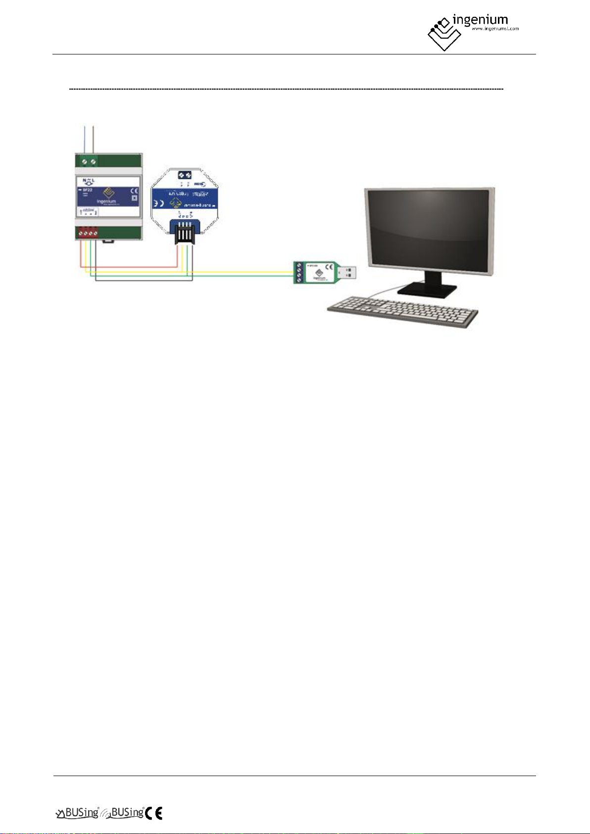
Previously we have to have the BUSing-MDAC-D gateway properly connected as follows:
NOT E: IT I S NOT N EC ES SAR Y T O PL A CE T HE P O WE R SUP P LY I F TH E RE I S SU FFIC IE NT V O LT AG E IN T HE
INS TA L LATI ON T O P OW ER IT . I T CO UL D B E TH AT THE P OW ER C OME S FRO M O TH ER E QU IP ME NT LI KE 6 E6 S,
4E4 S. .. ET C .
The only information to be turned to the gateway is the BUSing address. If you click on the icon to
reprogramme this node, no window will appear to confirm the programming, since the name assigned to
machine 1 in the gateway properties is necessary for point-to-point control linking on a screen/web server.
Page 16
PROGRAMMING MANUAL
BUSING-MDAC-DV1.0
Gateway
16Of17
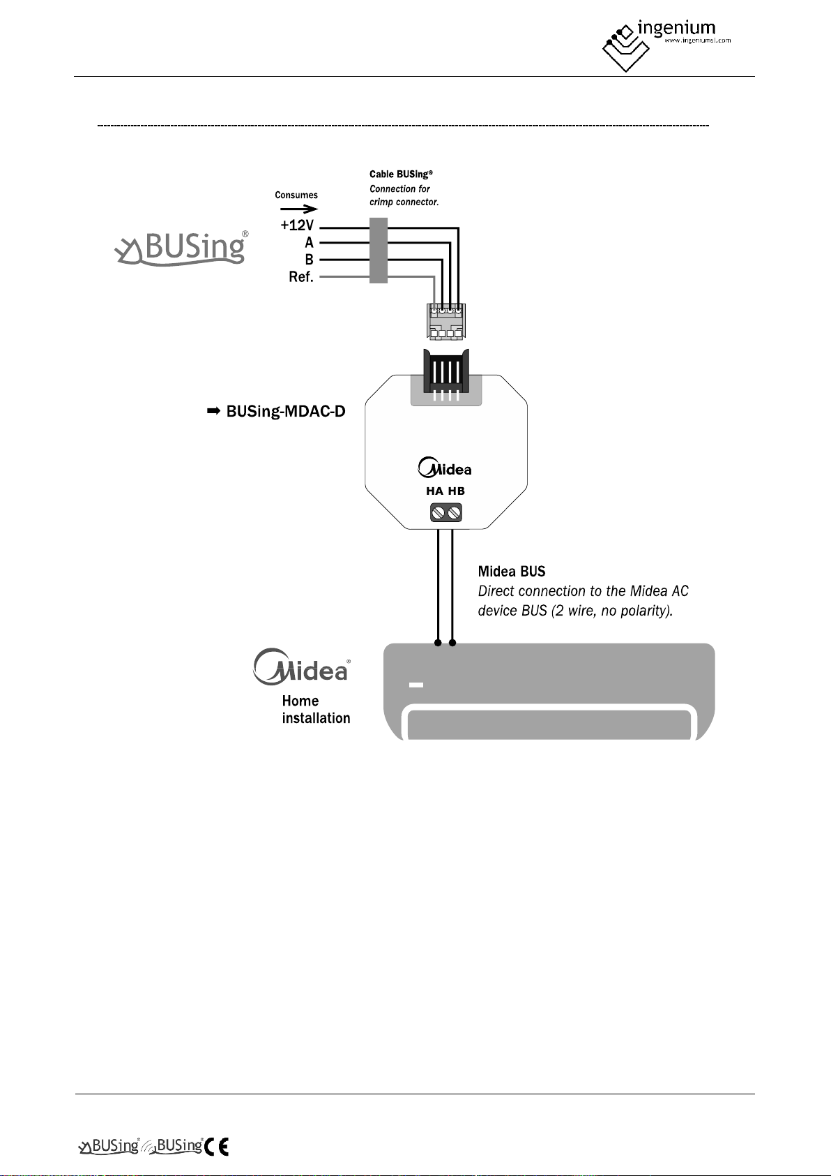
7 WIRING
Page 17
Parque Tecnológico de Asturias, Parcela 50,
33428 Llanera – Asturias - España
Tel (+34) 985 118 859
Fax (+34) 984 283 560
[email protected]
www.ingeniumsl.com
 Loading...