

Page 1

U s e r G u i d e
Product name
Range
: COUNTER TOP
:
iCT220/iCT250
INGENICO – 28-32 Boulevard de Grenelle –75015 Paris - FRANCE
Tél. 33(0)1 58 01 80 00 - Fax 33 (0)1 58 01 91 35
www.ingenico.com
Page 2

Contents
1. Introduction __________________________________________________ 3
2. Unpacking ___________________________________________________ 3
3. Recommendations_____________________________________________ 4
3.1. Security _____________________________________________________________4
3.2. Telephone emergency, hanging up _______________________________________4
3.3. Security of your terminal _______________________________________________5
3.4. Standard compliance marking ___________________________________________5
3.5. FCC compliance _______________________________________________________6
3.6. Main Characteristics ___________________________________________________8
4. Installation and connection _____________________________________ 9
4.1. Positioning the terminal ________________________________________________9
4.2. Connections__________________________________________________________9
4.3. Installing the iCT220/iCT250 – Cable fixing__________________________________9
4.3.1. Opening the cable cover_________________________________________________________ 9
4.3.2. Kit Magic Box installation _______________________________________________________ 10
4.3.3. Connect cables ________________________________________________________________ 11
4.3.4. Close cover ___________________________________________________________________12
4.4. Installation of the Magic Box ___________________________________________ 12
4.5. Installing SAM (Secure access module)___________________________________ 13
4.6. Installing MicroSD Card (optional)_______________________________________ 14
5. Installing a paper roll __________________________________________15
6. Daily use _____________________________________________________16
6.1. Keypad functions ____________________________________________________ 16
6.2. Adjusting the contrast ________________________________________________ 16
6.3. Card insertion _______________________________________________________ 17
6.3.1. Swiping a card_________________________________________________________________17
6.3.2. Inserting a chip card ____________________________________________________________17
6.3.3. Inserting a chip card in second reader (Optional) _____________________________________17
6.3.4. Reading Contactless (Optional) ___________________________________________________17
7. Maintenance _________________________________________________18
7.1. Paper roll ___________________________________________________________ 18
7.2. Cleaning of the terminal _______________________________________________ 19
7.3. Transport and storage ________________________________________________ 19
7.4. Troubleshooting _____________________________________________________ 19
7.5. End of life___________________________________________________________20
Product name : iCT220/iCT250 • 2/21
900002734 R11 000 05/4012
Copyright © 2012 Ingenico
All rights reserved
Page 3
1. Introduction
Thank you for choosing an Ingenico payment terminal.
We recommend you to read carefully this user guide: It gives you the necessary information
about safety precautions, unpacking, installation, and maintenance of your terminal.
CAUTION
To benefit from the guarantee-related product, and to respect the security, we ask you to
use only the power supply delivered in box with the product, entrusting maintenance
operations only to an authorized person.
Failure to comply with these instructions will void the manufacturer’s responsibility.
2. Unpacking
ADVICE
Carefully preserve the packaging of the iCT220/iCT250. It must be re-used whenever the
terminal is shipped.
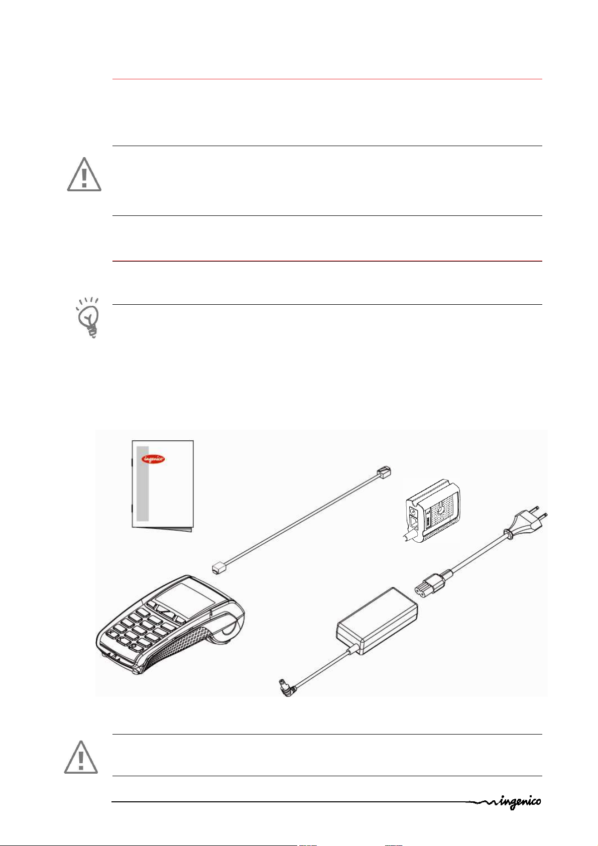
According to the model, the following items are included in the iCT220/iCT250 box
• The iCT220/iCT250 terminal equipped with its paper roll
• Magic box ( mandatory use )
• The main power supply with its cable connection (according to the national needs).
• The cable connection for the telephone network
• This installation guide
Magic box
Cable connection for the
telephone network
User guider
Desktop Power supply unit
iCT220/iCT250
terminal
CAUTION
The power supply unit provided with your equipment is specially designed for Ingenico
iCT220/iCT250 terminals. Do not use any other power supply.
Product name : iCT220/iCT250 • 3/21
900002734 R11 000 05/4012
Copyright © 2012 Ingenico
All rights reserved
Page 4

3. Recommendations
3.1. Security
Power on/Power down
To power on or power down the iCT220/iCT250 connect or disconnect the power supply
from the electric outlet.
Lithium battery
The iCT220/iCT250 is fitted with a lithium battery which is not accessible to the user. Only a
qualified technician may be authorized to open the unit and change this component.
Electrical power supply network
Provide an electrical outlet :
- located near the equipment and easily accessible
- which meets the standards and regulations in the country of use.
Telephone network
Provide a phone jack complying with standards and regulations in the country of use.
SAM/SIM or SD Memory Card compartment cover
Located under the terminal, it must be in place during normal operation of the terminal.
Cable compartment cover
The cable compartment cover is located under the terminal, it must be in place during
normal operation of the terminal.
3.2. Telephone emergency, hanging up
You have an urgent call to make, when iCT220/iCT250 hangs on the line.
In order to get a dial tone…
Place the handset in the hang up position and :
press the red key (=cancel)
or disconnect the power supply from the mains network
or disconnect the iCT220/iCT250 telephone connector from the telephone call socket,
and place the telephone connector into the telephone wall socket.
You will have a dial tone within 6 seconds.
Product name : iCT220/iCT250 • 4/21
900002734 R11 000 05/4012
Copyright © 2012 Ingenico
All rights reserved
Page 5
3.3. Security of your terminal
Upon receipt of your terminal you should check for signs of tampering of the equipment. It
is strongly advised that these checks are performed regularly after receipt. You should
check, for example: that the keypad is firmly in place; that there is no evidence of unusual
wires that have been connected to any ports on your terminal or associated equipment, the
chip card reader, or any other part of your terminal. Such checks would provide warning of
any unauthorised modifications to your terminal, and other suspicious behaviour of
individuals that have access to your terminal. Your terminal detects any “tampered state”.
In this state the terminal will repeatedly flash the message” Alert Irruption!” and further
use of the terminal will not be possible. If you observe the “Alert Irruption!” message, you
should contact the terminal helpdesk immediately.
You are strongly advised to ensure that privileged access to your terminal is only granted to
staff that have been independently verified as being trustworthy.
CAUTION
NEVER ask the customer to divulge their PIN Code. Customers should be advised to ensure
that they are not being overlooked when entering their PIN Code.
3.4. Standard compliance marking
iCT220
• This class (B) digital apparatus complies with Canadian ICES-003
• Cet appareil numérique de la classe (B) respecte toutes les exigences de la norme
NMB-003 du Canada.
iCT250
• Under Industry Canada regulations, this radio transmitter may only operate using an
antenna of a type and maximum (or lesser) gain approved for the transmitter by
Industry Canada. To reduce potential radio interference to other users, the antenna
type and its gain should be so chosen that the equivalent isotropically radiated
power (e.i.r.p.) is not more than that necessary for successful communication.
• Conformément à la réglementation d'Industrie Canada, le présent émetteur radio peut
fonctionner avec une antenne d'un type et d'un gain maximal (ou inférieur) approuvé
pour l'émetteur par Industrie Canada. Dans le but de réduire les risques de brouillage
radioélectrique à l'intention des autres utilisateurs, il faut choisir le type d'antenne et
son gain de sorte que la puissance isotrope rayonnée équivalente (p.i.r.e.) ne dépasse
pas l'intensité nécessaire à l'établissement d'une communication satisfaisante.
• This device complies with Industry Canada licence-exempt RSS standard(s).
Operation is subject to the following two conditions: (1) this device may not cause
interference, and (2) this device must accept any interference, including
interference that may cause undesired operation of the device.
• Le présent appareil est conforme aux CNR d'Industrie Canada applicables aux appareils
radio exempts de licence. L'exploitation est autorisée aux deux conditions suivantes :
(1) l'appareil ne doit pas produire de brouillage, et (2) l'utilisateur de l'appareil doit
accepter tout brouillage radioélectrique subi, même si le brouillage est susceptible
d'en compromettre le fonctionnement.
Product name : iCT220/iCT250 • 5/21
900002734 R11 000 05/4012
Copyright © 2012 Ingenico
All rights reserved
Page 6

iCT220 / iCT250
• conforms to the following standards and rules :
o IEC 60950-1 2
nd
Ed: Electrical safety of data processing equipment including
electrical office equipment
o FCC part 15 C (ICT250 ), FCC part 15 B(ICT220 )
o FCC part 68
o EN 55024
3.5. FCC compliance
FCC ID : XKB-ICT220 / XKB-ICT250 / XKB-ICT220V3 / XKB-ICT250V3
This equipment as been tested and found to comply with the limits for a Class B digital
device, pursuant to part 15 of the FCC Rules. These limits are designed to provide
reasonable protection against harmful interface in a residential installation. This equipment
generates uses and can radiate radio frequency energy and, if not installed and used in
accordance with instruction, may cause harmful interference to radio communications.
However, there is no guarantee that interference will not occur in a particular installation. If
this equipment does cause harmful interference to radio or television reception which can
be determined by turning the equipment off and on the user is encouraged to try to correct
interface by one more of the following measures :
• Reorient or relocate the receiving antenna.
• Increase the separation between the equipment and receiver.
• Connect the equipment into a outlet on circuit different from that to which the receiver
is connected.
• Consult the dealer or an experience radio/TV technician for help.
Part 68 of FCC Rules
US : IEOMM01BICT220 / IEOMM01BICT250
US : IEOMM01BICT220V3 / IEOMM01BICT250V3
This equipment complies with Part 68 of the FCC rules and the requirements adopted by
the ACTA. On the bottom of this equipment is a label that contains, among other
information, a product identifier in the format US: AAAEQ##TXXXX. If requested, this
number must be provided to the telephone company.
This equipment uses the following USOC jacks: (RJ11C).
A plug and jack used to connect this equipment to the premises wiring and telephone
network must comply with the applicable FCC Part 68 rules and requirements adopted by
the ACTA. A compliant telephone cord and modular plug is provided with this product. It is
designed to be connected to a compatible modular jack that is also compliant. See
installation instructions for details.
The REN is used to determine the number of devices that may be connected to a telephone
line. Excessive RENs on a telephone line may result in the devices not ringing in response to
an incoming call. In most but not all areas, the sum of RENs should not exceed five (5.0). To
be certain of the number of devices that may be connected to a line, as determined by the
total RENs, contact the local telephone company.
Product name : iCT220/iCT250 • 6/21
900002734 R11 000 05/4012
Copyright © 2012 Ingenico
All rights reserved
Page 7
If this equipment causes harm to the telephone network, the telephone company will notify
you in advance that temporary discontinuance of service may be required. If advance notice
is not practical, the telephone company will notify the customer as soon as possible.
Also, you will be advised of your right to file a complaint with the FCC if you believe it is
necessary.
The telephone company may make changes in its facilities, equipment, operations, or
procedures that could affect the operation of this equipment. If this happens, the
telephone company will provide advance notice in order for you to make the necessary
modifications to maintain uninterrupted service.
If trouble is experienced with this equipment, please contact INGENICO, or your local
INGENICO distributor or service center in the U.S.A. for repair and/or warrant information.
If your home has specially wired alarm equipment connected to the telephone line, ensure
the installation of this equipment does not disable your alarm equipment. If you have
questions about what will disable alarm equipment, consult your telephone company or a
qualified installer.
U.S.A service center:
Ingenico USA
6195 Shiloh Road, Suite D
Alpharetta, GA 30005
United States
Tel: +1(678) 456 1200 Fax: +1 (678) 456 1201
Email: info.us@ingenico.com
CAUTION
The user is cautioned that any changes or modification not approved by INGENICO could
void user’s authority to operate the equipment.
Product name : iCT220/iCT250 • 7/21
900002734 R11 000 05/4012
Copyright © 2012 Ingenico
All rights reserved
Page 8

3.6. Main Characteristics
Terminal
Weight about 325 g to 350 g full option
Size 185 x 83 x 63 mm (l x w x h)
Power supply unit (wall mounted)
Weight approx 115 g (without mains cable)
Size approx 77 x 25 x 89 mm (L x w x h)
Class Class II equipment
Input voltage 120V-60Hz
Max consumption 400 mA
The power supply unit is especially designed by the manufacturer for its terminals and so
must be used.
Desktop power supply unit
Weight approx 230 g (without mains cable)
Size approx 98 x 50 x 30 mm (L x w x h)
Class Class II equipment
Input voltage 100-240VCA-50-60 Hz
Max consumption 800 mA
Cable length
Power block cable approx 1,8 m
Telephone cable approx 3 m
Product name : iCT220/iCT250 • 8/21
900002734 R11 000 05/4012
Copyright © 2012 Ingenico
All rights reserved
Page 9

4. Installation and connection
Serial Link RS232
Telephone
USB Slave
Ethernet Link (Optional)
*
USB Host
Second Serial Link RS232
Power Supply
4.1. Positioning the terminal
Install the terminal on a flat surface, with an easy access to an electrical outlet and telephone
line. Place the terminal away from any heat source and protected from dust, vibrations and
electromagnetic radiations (away from video terminals, PC, anti-shoplifting barriers ...).
Operating conditions
Ambient temperature from +5°C to +40°C
Max relative humidity 85% at +40°C
Storage conditions
Storage temperature -20°C, +55°C
Max relative humidity 85% at +55°C
4.2. Connections
All connections are on the rear of the terminal protected by a cover.
*
according to the model
(Optional)*
4.3. Installing the iCT220/iCT250 – Cable fixing
4.3.1. Opening the cable cover
• Unclip the cover by pushing simultaneously on the clips
shown on the figure here below.
• Lift the cover rearward to remove it, as shown by arrows on the figure.
1
Product name : iCT220/iCT250 • 9/21
900002734 R11 000 05/4012
1
with your nails finger as
Copyright © 2012 Ingenico
All rights reserved
Page 10

caps
4.3.2. Kit Magic Box installation
WARNING
Connecting must be done when the terminal is powered off.
Follow the installation instructions shown below:
• Plug:
1
Power lead
2
Telephone line
3
Ethernet cable
4
Serial link RS232 cable
• Install caps in the lead-through (as indicated on
the figure).
• Close the compartment with the special cover
provided in the kit, like the procedure described at
chapter 4.3.4.
1
2
4
3
Product name : iCT220/iCT250 • 10/21
900002734 R11 000 05/4012
Copyright © 2012 Ingenico
All rights reserved
Page 11

4.3.3. Connect cables
Perform the following operations:
• Plug the telephone cable (1) into the telephone jack (3). Connect the other end into the
connection (4) of the magic box
• Plug the power leads (5) into the power outlet (6), connect the other end into the
power connection (7) of the magic box.
3
1
7
6
5
Plug: TNV-3 circuit: Telecommunication Network Voltage, as per safety standard EN 60950.
Product name : iCT220/iCT250 • 11/21
900002734 R11 000 05/4012
Copyright © 2012 Ingenico
All rights reserved
Page 12

4.3.4. Close cover
• To close the cover, start by inserting the clips
respectively first, as shown on the figure here below, and close the cover.
1
1
of the cover in their housing
4.4. Installation of the Magic Box
ADVICE
It is strongly recommended to attach the “Magic cable” to terminal’s work area in
order to reduce stress on the terminal and connection.
1 3
Examples of securing the “Magic Cable” are as illustrated:
1
Using the supplied cable tie to attach to a table leg (or similar)
2
Using the supplied cable tie and self-adhesive support
3
Using a counter-sunk screw (not supplied) to an appropriate surface
• The “Magic Cable” should be readily accessible for support and terminal helpdesk
diagnosis purposes.
2
Note: The connection Magic Box can also be attached using a VELCRO™ or other system.
Product name : iCT220/iCT250 • 12/21
900002734 R11 000 05/4012
Copyright © 2012 Ingenico
All rights reserved
Page 13

4.5. Installing SAM (Secure access module)
PRESS HERE
SAM
Cut corner
Adhesive
Cut corner
CAUTION:
Before starting, switch off the terminal by disconnecting the power supply.
In order to access the SAM card you must first remove the SAM compartment cover located
at the back of your terminal.
• Press down firmly in the middle of the cover and slide it as indicated by arrow on
the figure below.
• Insert the SAM Card into the slot marked (1) or(2). Take
care to ensure that the SAM Card is inserted in the correct
manner. The cut corner must be positioned as indicated
on the figure.
• To remove SAM card, we suggest you to use a piece of
adhesive previously pasted on both sides of the SAM as
shown here below
CAUTION:
Do not use any tools when installing or removing the SAM Card.
Replace the cover as illustrated by the procedure below:
Product name : iCT220/iCT250 • 13/21
900002734 R11 000 05/4012
Copyright © 2012 Ingenico
All rights reserved
Page 14

4.6. Installing MicroSD Card (optional)
CAUTION:
Before starting, switch off the terminal by disconnecting the power supply.
• Open the cover as indicated at chapter 4.5
• Insert completely the MicroSD Card into the
slot marked (MicroSD) as indicated on the
figure.
Take care to ensure that the MicroSD Card is
inserted in the correct manner. The
insertion position Card is engraved on the
terminal.
• To remove the MicroSD Card push on it with
your finger nails.
Product name : iCT220/iCT250 • 14/21
900002734 R11 000 05/4012
Copyright © 2012 Ingenico
All rights reserved
Page 15

5. Installing a paper roll
LIFT
Your terminal is supplied with one paper roll. When the paper roll is nearing the end, a red
line will appear on the paper, this indicates that the paper roll must be replaced.
CAUTION
Use only paper approved by the manufacturer (diameter 40 mm). Use of unsuitable paper
is likely to damage the printer of your terminal (see characteristics at the chapter 7.1).
• Open the paper compartment by lifting the catch located at the rear of the
iCT220/iCT250 and pulls the cover to the rear of the terminal.
ATTENTION
Do not force the cover against the cables.
• Insert the paper roll in the compartment following the directions shown on the
figure below.
• Pull the paper up to the top of the terminal and hold it in this position.
• Maintain the paper and close the lid.
• Press the top of the lid in the center as shown by arrow, until it clips into position.
ADVICE
If you are inserting a new roll, tear off the first length (one complete turn).
Product name : iCT220/iCT250 • 15/21
900002734 R11 000 05/4012
Copyright © 2012 Ingenico
All rights reserved
Page 16

6. Daily use
6.1. Keypad functions
1
2
3
6
5
4
1
NAVIGATION keys in the menus – Interactive keys for use between the screen
2
FUNCTION keys F
3
CANCEL key (red)
4
CLEAR key (yellow) / Feed paper (long press)
5
VALIDATION key (green)
6
Dot Key
6.2. Adjusting the contrast
No contrast management for the Colour display
The screen of your chart is 128 x 64 pixels, illuminated with white light.
If you wish to increase or to decrease the contrast of the characters displayed on screen,
press simultaneously on the (dot key) and key in order to decrease the
contrast, or the (dot key) and key in order to increase.
Keep pressing the keys as long as necessary.
Product name : iCT220/iCT250 • 16/21
900002734 R11 000 05/4012
Copyright © 2012 Ingenico
All rights reserved
Page 17

6.3. Card insertion
Active Zone
6.3.1. Swiping a card
• Slide the card in the reader with magnetic
strip facing left
Swipe the card with constant speed, not
too slow not too fast, to maximize the
reading and avoid annoying repetitions.
6.3.2. Inserting a chip card
• Chip Cards should be inserted into the
card reader as illustrated with the chip
facing up
6.3.3. Inserting a chip card in second reader
(Optional)
Is located on back of the terminal.
• Insert the card up side down, magnetic strip
visible. (chip no visible)
6.3.4. Reading Contactless (Optional)
• Bring the card quickly up to the active zone above the display (at about 1cm). Keep
the card close to the display during the transaction
Your contactless terminal has a row of four status lights that are visible on display.
• When a contactless transaction is started the first (left hand) status light will be lit
steadily; this indicates that the
contactless display is in use but a card is
not being read.
• When a contactless card is presented to
the contactless active zone during a
transaction, the second, third and
fourth status lights will be lit in turn.
The card read is successful when all four
status lights are lit and the confirmation
tone is heard.
Contact’less
Green
lights
Product name : iCT220/iCT250 • 17/21
900002734 R11 000 05/4012
Copyright © 2012 Ingenico
All rights reserved
Page 18

7. Maintenance
WARNING
Before making any operations of maintenance in the terminal, make sure that
the power supply is disconnected.
7.1. Paper roll
Characteristics Precisions
Colour White
Width 58 mm
Diameter 40 mm max.
• The thermal paper can be deteriorated by poor storage conditions, so we
recommend you to avoid:
– storage in hot wet places (near to air-conditioner, humidity higher than 85%)
– exposure to sunlight or ultraviolet for long periods
– contact with organic solvents (solvent type adhesive)
– direct contact with materials containing plasticizers (PVC transparent
folders or envelopes)
– direct contact with «diazo» papers
– direct contact with water
– Rubbing or pressing the paper too strongly
CAUTION
In order to benefit from the complete guarantee of the product, only heat sensitized paper
approved by the manufacturer can be used.
Product name : iCT220/iCT250 • 18/21
900002734 R11 000 05/4012
Copyright © 2012 Ingenico
All rights reserved
Page 19

7.2. Cleaning of the terminal
First of all, unplug all the wires from the terminal.
Good rules for proper cleaning of the terminal are:
• Use a soft cloth that is very slightly soaked with soapy water to clean the outside of
the terminal.
• Do not clean the electrical connections.
• Do not use in any case, solvents, detergents or abrasive products:
Those materials might damage the plastic or electrical contacts.
• Avoid exposing the terminal to the direct rays of the sun.
• Do not put anything into the slot of the smart card reader
7.3. Transport and storage
• Use the original packaging for any unit or stored.
•
Disconnect all cables from the terminal during the transport.
7.4. Troubleshooting
The terminal does not turn on or does not connect to the telephone line
• Check the power supply and telephone line cables
• Check for electrical power network
The terminal fails to establish a telephone connection
• Check that the tone of the phone line is free
• Check the configuration of the phone line and number to call
• Get support from technical
Cards are not read
• Check that the magnetic card is swiped correctly (with magnetic stripe facing left)
• Swipe again the card with a constant and quick movement
• Verify that the magnetic strip is not damaged, grooved or cracked
• Make sure you have inserted correctly the smart card into the smart card reader
and removed the card only after the transaction
The ticket is not printed
• Check the presence and proper positioning of the paper roll.
Possibly adjust the paper roll following instructions present in this manual
• Check the type of paper used (thermal paper must be used)
Product name : iCT220/iCT250 • 19/21
900002734 R11 000 05/4012
Copyright © 2012 Ingenico
All rights reserved
Page 20

7.5. End of life
The product belongs to the family of electrical and electronic equipment. Therefore, it is
subjected to the WEEE directive which requires the collection and the recycling at the end
of life product.
The Ingenico products present the symbol for the marking of electrical and electronic
equipment as required by the WEEE Directive.
The crossed-out wheeled bin printed on the product gives the information about
the requirement not to dispose of WEEE as unsorted municipal waste and to
collect such WEEE separately.
To assure that the product is collected and recycled with respect to the environment, you
must contact your supplier (in defect, contact the Ingenico local office or the commercial
head office in charge of your country on www.ingenico.com, « contact us » page).
The abandonment or uncontrolled disposal of waste can cause harm to environment and to
human health. So, by recycling your product in a responsible manner, you contribute to the
preservation of natural resources and to the protection of human health.
Product name : iCT220/iCT250 • 20/21
900002734 R11 000 05/4012
Copyright © 2012 Ingenico
All rights reserved
Page 21

Ingenico
*296114093
AE
*
“This Document is Copyright © 2012 by INGENICO Group. INGENICO retains full copyright ownership,
rights and protection in all material contained in this document. The recipient can receive this
document on the condition that he will keep the document confidential and will not use its contents
in any form or by any means, except as agreed beforehand, without the prior written permission of
INGENICO. Moreover, nobody is authorized to place this document at the disposal of any third party
without the prior written permission of INGENICO. If such permission is granted, it will be subject to
the condition that the recipient ensures that any other recipient of this document, or information
contained therein, is held responsible to INGENICO for the confidentiality of that information.
Care has been taken to ensure that the content of this document is as accurate as
possible. INGENICO however declines any responsibility for inaccurate, incomplete or outdated
information. The contents of this document may change from time to time without prior notice, and
do not create, specify, modify or replace any new or prior contractual obligations agreed upon in
writing between INGENICO and the user.
INGENICO is not responsible for any use of this device, which would be non consistent with the
present document.
All trademarks used in this document remain the property of their rightful owners.”
Your contact
28-32 Boulevard de grenelle
75015 Paris - France
Tél.: + 33 1 58 01 80 00 - Fax: + 33 1 58 01 91 35
www.ingenico.com
Product name : iCT220/iCT250 • 21/21
900002734 R11 000 05/4012
Copyright © 2012 Ingenico
All rights reserved
 Loading...