

Infratech W series, WD series Installation Use & Care Instructions
ALL WEATHER W-SERIES AND WD-SERIES
QUARTZ TUBE ELECTRIC INFRARED RADIANT HE
TABLE OF CONTENTS
Warnings 2
Installation Instructions 3
Wiring Instructions 3
Mounting Instructions 4
Replacement Element Installation 5
Replacement Parts 5
Heater Coverage Areas 6
General Notes 6
Maintenance Instructions 6
Trouble Shooting 7
Location Suggestions 7
Warranty 8
WARNINGS
READ ALL INSTRUCTIONS BEFORE USING HEATER
Unit may be a source of possible shock. NEVER attempt to service heater without disconnecting its power source.
S
ource of possible ignition.
CAUTION
High Temperature, risk of fire, keep electrical cords, drapery, furnishings and other combustibles at least 3 feet
0.9m) from the front of heater and away from sides and rear.
(
MOUNTING HEIGHT/CLEARANCES
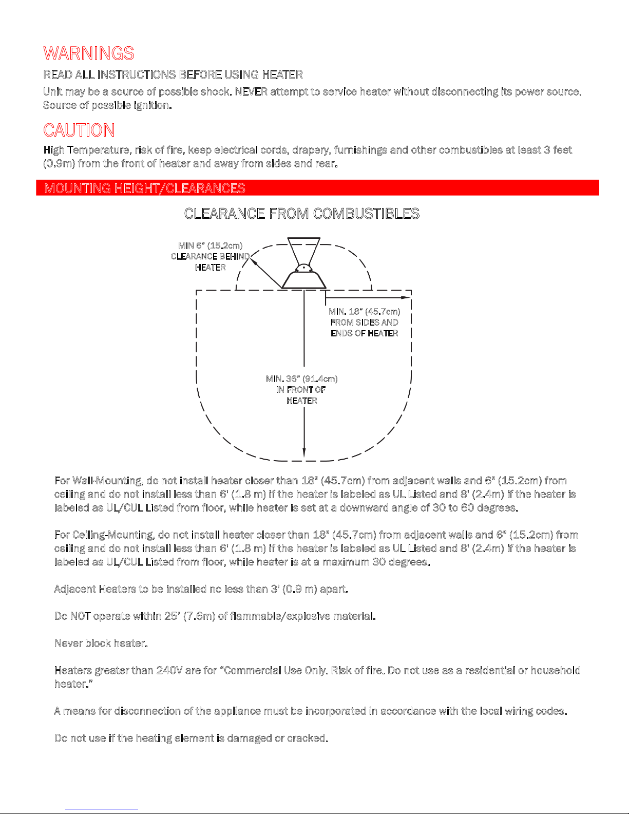
CLEARANCE FROM COMBUSTIBLES
MIN 6” (15.2cm)
CLEARANCE BEHIND
HEATER
MIN. 18” (45.7cm)
FROM SIDES AND
NDS OF HEATER
E
MIN. 36” (91.4cm)
IN FRONT OF
EATER
H
• For Wall-Mounting, do not install heater closer than 18" (45.7cm) from adjacent walls and 6" (15.2cm) from
c
eiling and do not install less than 6' (1.8 m) if the heater is labeled as UL Listed and 8' (2.4m) if the heater is
abeled as UL/CUL Listed from floor, while heater is set at a downward angle of 30 to 60 degrees.
l
or Ceiling-Mounting, do not install heater closer than 18" (45.7cm) from adjacent walls and 6" (15.2cm) from
• F
c
eiling and do not install less than 6' (1.8 m) if the heater is labeled as UL Listed and 8' (2.4m) if the heater is
abeled as UL/CUL Listed from floor, while heater is at a maximum 30 degrees.
l
• A
djacent Heaters to be installed no less than 3' (0.9 m) apart.
o NOT operate within 25’ (7.6m) of flammable/explosive material.
• D
ever block heater.
• N
eaters greater than 240V are for “Commercial Use Only. Risk of fire. Do not use as a residential or household
• H
h
eater.”
means for disconnection of the appliance must be incorporated in accordance with the local wiring codes.
• A
o not use if the heating element is damaged or cracked.
• D
“IMPORTANT INSTRUCTIONS”
2
“SAVE THESE INSTRUCTIONS”

INSTALLATION INSTRUCTIONS
This heater must be permanently installed and hard wired by a licensed electrician in accordance with local
electrical codes. Assembly procedure must be performed with no electrical power to unit.
Step 1: Check UL/CUL/CE label on heater for proper voltage.
Step 2: Follow supplied wiring instructions. (See wiring instructions below)
Step 3: Heater must be mounted with reflector angled down.
Step 4: All electrical connections must be in compliance with the National Electric Code (NEC) and local codes for
outdoor wiring.
Step 5: Use only wiring components UL/CUL/CE listed for outdoor use with IPX4 minimum rating.
WIRING INSTRUCTIONS
The heater is drilled and threaded for standard ½” conduit fittings. The installing electrician will need to provide the
appropriate rigid metallic, flexible or liquid tight conduit for the installation.
• Observe local electrical code regulations.
• Remove cover plate from junction box.
• Attach conduit.
• Use only copper or aluminum wire
suitable for 90°C.
• Replace cover plate.
GREEN GROUND
WIRE SCREW
Connect power with flexible
conduit or appropriate cord
to allow heater to be swiveled.
The Junction Box inlet hole is
T
sized for a standard ½” weather
tight conduit fitting and has a
locknut located on the inside of
the box for fastening.
Junction Box on top of the heater
has a gasket
has a gasket side access cover
3
 Loading...