


SMT-BD2
gb
DIGITAL SERVO DRIVE
FOR SINUSOIDAL
BRUSHLESS AC MOTORS
SMT-BD2
1

SMT-BD2
2
SMT-BD2

SMT-BD2
WARNING !
This is a manual describing a series of servo amplifiers having output capability suitable for driving AC brushless
servo motors equipped with an encoder only or an encoder plus Hall effect sensors for the position feedback. This
manual may be used in conjunction with appropriate and referenced drawings pertaining to the various specific
models.
Maintenance procedures should be attempted only by highly skilled technicians (EN 60 204.1 standard)
using proper test equipment.
The conformity with the standards and the "CE" approval are only valid if the items are installed according to the
recommendations of the racks and amplifiers manuals.
Any contact with electrical parts, even after power down, may involve physical damage.
Wait for at least 5 minutes after power down before handling the amplifiers (a residual voltage of several hundreds
of Volts may remain during a few minutes).
INFRANOR drives are conceived to be best protected against electrostatic discharges. However, some
components are particularly sensitive and may be damaged. Before handling the drives and, particularly, before
any contact with the connectors, the user himself must be earthed. Place or store the drives on conducting or
electrostatically neutral areas but not on plastic areas, carpeting or insulation material that may be electrostatically
loaded.
INFRANOR does not assume any responsibility for any physical or material damage due to improper handling or
wrong descriptions of the ordered items.
Infranor reserves the right to change any information contained in this manual without notice.
Any intervention on the items, which is not specified in the manual, will immediately cancel the warranty.
This manual is a translation of the original document and does not commit INFRANOR's responsibility.
The french manual is the only reference document.
© INFRANOR, February 2005. All rights reserved.
Issue: 3.0
!
SMT-BD2
3

SMT-BD2
4
SMT-BD2

SMT-BD2
Contents
CONTENTS............................................................................................................................................. 5
CHAPTER 1 - GENERAL DESCRIPTION ............................................................................................. 7
1 - INTRODUCTION............................................................................................................................. 7
2 - GENERAL DESCRIPTION.............................................................................................................. 7
3 - REFERENCE TO THE STANDARDS............................................................................................. 8
4 - REFERENCE TO OTHER DOCUMENTS....................................................................................... 8
CHAPTER 2 – SPECIFICATIONS.......................................................................................................... 9
1 - TECHNICAL SPECIFICATIONS..................................................................................................... 9
1.1 - Current ratings for the 220 VAC amplifier version.................................................................... 9
1.2 - Current ratings for the 400 VAC amplifier version.................................................................. 10
1.3 - Other specifications................................................................................................................ 11
2 - BLOCK DIAGRAM.........................................................................................................................13
3 - MAIN PROTECTIONS .................................................................................................................. 14
3.1 - Displayed protections............................................................................................................. 14
3.2 - Fuse protection....................................................................................................................... 15
CHAPTER 3 - INPUTS - OUTPUTS.................................................................................................... 16
1 - CONNECTORS LOCATION......................................................................................................... 16
1.1 - RACK connectors................................................................................................................... 16
1.2 - Amplifier connectors............................................................................................................... 16
2 - X5 SERIAL LINK CONNECTOR (SUB D 9 POINTS MALE)............................................................... 16
3 - X1 ENCODER FEEDBACK CONNECTOR (SUB D 15 POINTS FEMALE)......................................... 17
3.1 - X1 connector for TTL incremental encoder configuration...................................................... 17
3.2 - X1 connector for TTL incremental encoder & HES configuration.......................................... 18
3.3 - X1 connector for absolute single turn Sin/Cos encoder configuration................................... 19
3.4 - X1 connector for other sin/cos encoder configurations.......................................................... 20
4 - X4 COMMAND CONNECTOR (SUB D 25 POINTS MALE)................................................................ 21
4.1 - Specification of the analog inputs / outputs............................................................................ 22
4.2 - Specification of the logic inputs / outputs...............................................................................23
5 - X2 POSITION OUTPUT CONNECTOR (SUB D 25 POINTS FEMALE).............................................. 24
Specification of the TTL encoder output.........................................................................................24
CHAPTER 4 - CONNECTIONS............................................................................................................ 25
1 - CONNECTION DIAGRAMS.......................................................................................................... 25
1.1 - Rack power supply and motor connection............................................................................. 25
1.2 - Amplifier i/o connections......................................................................................................... 25
1.3 - RS-232 serial link connection................................................................................................. 27
2 - WIRING (ACCORDING TO CEI 801 AND EN 55011 STANDARDS) ....................................................... 28
2.1 - GND wiring and grounding..................................................................................................... 28
2.2 - Motor and sensors cables ...................................................................................................... 28
2.3 - Input command and serial link cables.................................................................................... 28
3 - 360° SHIELD ON THE CONNECTORS ........................................................................................ 29
CHAPTER 5 - ADJUSTABLE FUNCTIONS ........................................................................................ 30
1 - HARDWARE ADJUSTMENTS...................................................................................................... 30
2 - ADJUSTABLE PARAMETERS ..................................................................................................... 33
CHAPTER 6 - COMMISSIONING......................................................................................................... 34
1 - CHECKING THE AMPLIFIER CONFIGURATION........................................................................ 34
1.1 - Standard amplifier configuration............................................................................................. 34
1. 2 - Encoder configuration............................................................................................................ 34
Contents
5

SMT-BD2
1. 3 - Hall Effect Sensors configuration...........................................................................................35
1. 4 - Motor thermal sensor configuration.......................................................................................35
1.5 - Current loops adjustments......................................................................................................36
2 - PUTTING INTO OPERATION ....................................................................................................... 38
3 - AMPLIFIER COMMISSIONING AND ADJUSTMENT...................................................................38
3.1 - Amplifier setup........................................................................................................................38
3.2 - Motor Hall Effect Sensors adjustment .................................................................................... 39
3.3 - Absolute single turn Sin/Cos encoder adjustment.................................................................. 39
3.4 - Amplifier parameter setting.....................................................................................................40
3.5 - Amplifier auto-tuning with an unbalanced load...................................................................... 40
3.6 - Saving of the amplifier parameters......................................................................................... 41
3.7 - Motor phasing at power up.....................................................................................................41
3.8 - Parameters adjustment to a linear motor ...............................................................................42
CHAPTER 7 – FAULT FINDING...........................................................................................................43
1 - SYSTEM FAULT............................................................................................................................43
2 - STORED FAULTS.........................................................................................................................43
2.1 - "BUSY" fault........................................................................................................................... 43
2.2 - "EEPROM" fault......................................................................................................................44
2.3 - "°C MOTOR" fault...................................................................................................................44
2.4 - "UNDERVOLT." fault .............................................................................................................. 44
2.5 - "°C AMPLIFIER" fault..............................................................................................................44
2.6 - "POWER STAGE" fault...........................................................................................................44
2.7 - "HES" fault .............................................................................................................................. 44
2.8 - "ENCODER" fault.................................................................................................................... 45
2.9 - "COUNTING" fault ..................................................................................................................46
2.10 - "I2t" fault ................................................................................................................................47
2.11 - "TRACKING" fault.................................................................................................................47
2.12 - "ADC" fault............................................................................................................................47
3 - OPERATING PROBLEMS.............................................................................................................48
3.1 - Motor supplied, but no torque................................................................................................. 48
3.2 - Motor does not move..............................................................................................................48
3.3 - Shaft locked, eratic oscillations or rotation at maximum speed..............................................48
3.4 - Discontinuous motor rotation with zero torque positions.......................................................48
3.5 - Motor drift with analog input command at zero speed............................................................ 48
3.6 - Loud crackling noise in the motor at standstill........................................................................ 48
3.7 - Loud noise in the motor at standstill and when running.........................................................48
3.8 - Position control not possible with the NC ............................................................................... 48
4 - SERVICE AND MAINTENANCE ................................................................................................... 49
CHAPTER 8 - APPENDIX..................................................................................................................... 50
1 - USE OF THE LIMIT SWITCHES & "CVO" INPUTS......................................................................50
2 - USE OF THE "AMP. READY" & "POWER READY" OUTPUTS.................................................... 50
3 - SPEED FOLLOWING ERROR PROTECTION .............................................................................50
2
4 - I
T PROTECTION.......................................................................................................................... 51
4.1 - Current limitation in Fusing mode........................................................................................... 51
4.2 - Current limitation in Limiting mode ......................................................................................... 52
5 - COGGING COMPENSATION OPTION ........................................................................................ 52
5.1 - Amplifier configuration ............................................................................................................ 52
5.2 - cogging compensation setup for rotating motors ...................................................................53
5.3 - cogging compensation setup for linear motors....................................................................... 53
6 - AMPLIFIER TYPES.......................................................................................................................54
6
Contents

SMT-BD2
Chapter 1 - General description
1 - INTRODUCTION
Series SMT-BD2 digital servo modules are sinusoidal PWM power amplifiers that provide speed and torque/force
control for AC brushless motors equipped with encoder only or encoder with Hall Effect Sensors (HES) for the
position feedback. The speed or torque/force input command is a +/-10 V analog signal voltage.
The SMT-BD2 digital servo drive is 220 VAC or 400 VAC main operated. The SMT-BD2 plug-in system with 400
VAC power supply is available as a multiaxis version that can receive up to three axes in a standard 19" rack
including the power supply. The SMT-BD2 plug-in system with 220 VAC power supply is available as a single-axis
block version or as a multiaxis version that can receive up to six axes in a standard 19" rack including the power
supply.
2 - GENERAL DESCRIPTION
Series SMT-BD2 amplifiers have their own DC/DC converter to provide the appropriate supply voltage (+5 V,
+15 V, -15V). The source supply voltage for the logic board is the auxiliary 310 VDC supply voltage. The auxiliary
supply voltage allows to have the position output signals still available when the power supply voltage is turned off.
Each module is packaged as a 6 U "double Eurocard":
- one power board with IGBT transistors
- one logic board with DSP (Digital Signal Processing).
The SMT-BD2 amplifier directly controls the motor torque/force and speed by means of the information provided
by an encoder feedback device. The sinusoidal current commutation based on encoder feedback provides smooth
motor torque/force control.
The SMT-BD2 amplifier can be configurated for various encoder types feedback. The appropriate encoder input
configuration is selectable by jumpers.
- With an incremental encoder only, a motor phasing procedure must be executed at each amplifier power up
before the motor enabling.
- With an incremental encoder + HES feedback from the motor, the motor phasing procedure is no more
necessary and the servo motor can immediately be enabled after the amplifier power up.
- With an absolute single turn SinCos encoder feedback from the motor (Heidenhain ERN 1085 or compatible),
the servo motor can also immediately be enabled after the amplifier power up.
The motor speed or torque/force input command is a +/-10 V analog voltage. The motor position output is
available as two A and B encoder type channels in quadrature, and one Z marker pulse per revolution via RS422
line drivers. The ratio between the number of pulses on the motor encoder and the number of pulses on the SMT-
BD2 amplifier encoder output is programmable.
The amplifier faults are displayed on the front panel and can also be read via the serial link.
All control parameters are programmable by means of the serial link and saved in an EEPROM. The autoconfiguration and auto-tuning functions allow an easy and quick commissioning of the amplifier.
The Visual Drive Setup software, which is IBM-PC compatible with the WINDOWS® operating system, allows the
clear display and easy modification of all amplifier parameters. The Visual Drive Setup software also includes a
digitizing oscilloscope function that is particularly useful for the drive commissioning and maintenance.
Chapter 1 - General description
7

SMT-BD2
3 - REFERENCE TO THE STANDARDS
The 220 VAC version of the SMT-BD2 amplifiers operating in the BF rack, which is equipped with the mains filter
BF-35 or 70, has been approved for its conformity with the Electromagnetic Compatibility standards:
EN 55011, Group 1, Class A regarding the conducted and radiated radioelectric disturbances,
CEI 801 - 2 - 3 - 4 regarding the immunity.
The 220 VAC version of the SMT-BD2 amplifiers operating in the single axis BM20 A – BMM05F – BMM05AF,
which is equipped with appropriate mains filter (FN 612-20/06 or FN 356-16/06) has been approved for its
conformity with the Electromagnetic Compatibility standards:
EN 55011, Group 1, Class A regarding the conducted and radiated radioelectric disturbances,
CEI 801 - 2 - 3 – 4 regarding the immunity.
The 400 VAC version of the SMT-BD2 amplifiers operating in the BF-400 rack, which is equipped with the mains
filter F400-35 or 70, has been approved for its conformity with the Electromagnetic Compatibility standards:
EN 55011, Group 1, Class A regarding the conducted and radiated radioelectric disturbances,
CEI 801 - 2 - 3 - 4 regarding the immunity.
Standard to be applied to the electrical equipments of industrial machines: EN 60204.1.
The SMT-BD2 amplifiers have been "CE" marked since year 2000.
4 - REFERENCE TO OTHER DOCUMENTS
♦ BF-400 rack – for the use of the 400 VAC amplifier version in a multiaxis rack.
♦ BF rack – for the use of the 220VAC amplifier version in a multiaxis rack.
♦ BM20A/BMM05F/05AF single-axis rack – for the use of the 220 VAC amplifier version in a single-axis rack.
8
Chapter 1 – General description

SMT-BD2
Chapter 2 – Specifications
1 - TECHNICAL SPECIFICATIONS
1.1
- CURRENT RATINGS FOR THE 220 VAC AMPLIFIER VERSION
Operating voltage DC bus 310 VDC (270 VDC < DC bus < 340 VDC max.)
Auxiliary supply voltage 310 VDC ( 200 VDC < Uaux < 340 VDC max.)
Motor terminal to terminal output voltage 200 Vrms for 310 VDC bus
Authorized output currents for current pulse mode operation (I2t protection in fusing mode)
AMPLIFIER
(Vrms) 1 s WITHOUT
SMT-BD2 - 220/04 240 4,4 2
SMT-BD2 - 220/08 240 8,8 4
SMT-BD2 - 220/12 240 13,8 6
SMT-BD2 - 220/17 240 17,7 8,5
SMT-BD2 - 220/30 240 30,8 10 12 15
SMT-BD2 - 220/30r 240 30,8 10 15
SMT-BD2 - 220/45 240 48,6 10 15 20
SMT-BD2 - 220/45r 240 48,6 10 20 23
SMT-BD2 - 220/60 240 61 10 19 25
SMT-BD2 - 220/60r 240 61 12 26 30
SMT-BD2 - 220/70 240 70 25 30 35
SMT-BD2 - 220/100 240 100 25 30 35
Authorized output currents for continuous current mode operation (I
AMPLIFIER TYPE
(Vrms) 1 s WITHOUT
SMT-BD2 - 220/04 240 4,4 2
SMT-BD2 - 220/08 240 8,8 4
SMT-BD2 - 220/12 240 13,8 6
SMT-BD2 - 220/17 240 17,7 8,5 8,5
SMT-BD2 - 220/30 240 30,8 8,5 12 15
SMT-BD2 - 220/30r 240 30,8 10 15
SMT-BD2 - 220/45 240 48,6 8,5 15 18
SMT-BD2 - 220/45r 240 48,6 10 20 23
SMT-BD2 - 220/60 240 61 8,5 17 20
SMT-BD2 - 220/60r 240 61 12 26 30
SMT-BD2 - 220/70 240 70 17 30 35
SMT-BD2 - 220/100 240 100 25 30 35
* Maximum ambient temperature = + 40° C, fan 1 = 56 l/s, fan 2 = 90 l/s.
Note
: The SMT-BD2-X/Xr amplifier types are equipped with an additional heatsink in order to improve the heat
dissipation and increase their rated current. The width of these amplifier types is then 18 TE instead of 12 TE.
Minimum inductance between phases 1 mH
U rated Imax (Arms)
Urated Imax (Arms)
Max. authorized rated current (Arms)
of the amplifier
FAN TYPE
FAN*
2
t protection in limiting mode)
Max. authorized continuous current (Arms) of
FAN*
1*
the amplifier
FAN TYPE
1*
FAN TYPE
2*
FAN TYPE
2*
Chapter 2 - Specifications
9

SMT-BD2
Conformity with the standards: CE approval - EMC standards
with multiaxis power supply configuration Immunity: CEI standards 801- 2 - 3 - 4
BF rack and mains filter BF-35 or 70, Conducted and radiated disturbances: EN 55011,
or SMTB.M 20 A single-axis rack and BF 35 filter. Group 1, class A
"360°" shields; equipotentiality according to the - Electrical standards for industrial machines:
wiring rules. EN 60204.1: - Insulator: 1500 VAC/1 min.
- Leakage current > 3 mA
(EMI filters)
Temperature range * storage - 20°C to + 70°C
* operation 5°C to +40°C
From 40°C on, the rated currents
must be reduced of 3 %/°C.
Max. temperature: 50°C
1.2-C
URRENT RATINGS FOR THE 400 VAC AMPLIFIER VERSION
Operating voltage DC bus 565 VDC (480 VDC < DC bus < 685 VDC max.)
Auxiliary supply voltage 310 VDC ( 200 VDC < Uaux < 340 VDC max.)
Motor terminal to terminal output voltage 380Vrms for 565 VDC bus
Authorized output currents for current pulse mode operation (I
2
t protection in fusing mode)
AMPLIFIER
(Vrms) 1 s WITHOUT
U rated
Imax (Arms)
Max. authorized rated current
(Arms) of the amplifier
FAN TYPE
FAN*
2*
SMT-BD2 - 400/15 400 15.5 5 7.5
SMT-BD2 - 400/30 400 30 8 15
SMT-BD2 - 400/45 400 48 10 19
SMT-BD2 - 400/60 400 60 not used 28
Authorized output currents for continuous current mode operation (I
2
t protection in limiting mode)
AMPLIFIER TYPE
(Vrms) 1 s WITHOUT
U rated
Imax (Arms)
Max. authorized continuous
current (Arms) of the amplifier
FAN TYPE
FAN*
2*
SMT-BD2 - 400/15 400 15.5 not used 5
SMT-BD2 - 400/30 400 30 not used 10
SMT-BD2 - 400/45 400 48 not used 15
SMT-BD2 - 400/60 400 60 not used 23
* Maximum ambient temperature = + 40° C, fan 2 = 90 l/s.
Minimum inductance between phases 2 mH
Conformity with the standards: CE approval - EMC standards
with multiaxis power supply configuration Immunity: CEI standards 801- 2 - 3 - 4
BF-400 rack and mains filter F400-35 or 70. Conducted and radiated disturbances: EN 55011,
"360°" shields; equipotentiality according to the Group 1, class A
wiring rules. - Electrical standards for industrial machines:
EN 60204.1: - Insulator: 2500 VDC/1 min.
- Leakage current > 3 mA
(EMI filters without condensators)
Temperature range * storage - 20°C to + 70°C
* operation 5°C to +40°C
From 40°C on, the rated currents must be reduced
of 3 %/°C.
Max. temperature: 50°C
10
Chapter 2 – Specifications

SMT-BD2
1.3 - OTHER SPECIFICATIONS
PWM switching frequency 10 KHz
Current regulator (PI) Adjusted to motor
Current loop bandwidth Cut-off frequency for 45° phase shift > 1 KHz
Internal current limitation Maximum current range : 20 % to 100 % of Imax
Rated current range : 20 % to 50 % of Imax
Imax = amplifier current rating
Analog current limitation input 0 V to 10 V, resolution = 12 bits
100 % to 0 % of the Maximum current value
Maximum current available if not connected
Analog speed command input ±10 V, standard resolution = 12 bits
Resolution = 16 bits optional
Motor accel/decel ramp range From 0 to 30 s between zero speed and
max. speed
Speed regulator P, PI or PI
Anti-wind-up system of the integrator
Adjustable digital gains
Antiresonance filter
Speed loop bandwidth Cut-off frequency for 45° phase shift
Selectable : 50 Hz, 75 Hz or 100 Hz
(see Note 1)
Speed range 2048 : 1 with 12 bit input command
32768 : 1 with 16 bit input command
Max. motor speed Adjustable from 100 rpm to 25000 rpm
(see Note 2)
Hall sensors input Selectable by jumpers : 120° or 60° HES type
5 V or 15 V supply voltage
HES sequence error detection
2
Sampling period = 0,5 ms
1
2
1
Note 1 :
The maximum speed loop bandwidth value not only depends on the amplifier specification but also on the feedback encoder
resolution and the motor mechanical load. The lower the encoder resolution, the lower the servo loop gains and the servo loop
bandwidth, to avoid any motor noise due to signal quantization effect. The mechanical load backlashes and elasticity can also
limit the servo loop gains and bandwidth to avoid mechanical resonances. The optimal servo loop gain value for a given
application can be automatically calculated by using the amplifier Auto-tuning procedure.
2
Note 2 :
The Max. motor speed value not only depends on the motor specification but also on the encoder specification. Both following
conditions must be answered for taking into account the maximum encoder pulse frequency value :
Max. motor speed (rpm) < 60 x 10
Max. motor speed (rpm) < 60 x Encoder pulse frequency limit (Hz) / Number of encoder pulses per revolution.For example with
the ROD426 (Heidenhain) series encoder, the pulse frequency limit value is 300 KHz. So, a motor equipped with a ROD426
encoder having a resolution of 5000 ppr cannot exceed 3600 rpm.
Chapter 2 - Specifications
6
/ Number of encoder pulses per revolution
11

SMT-BD2
Encoder input Selectable by jumpers :
Quadrature TTL A & B with Z marker pulse
RS 422 line receiver
maximum pulses frequency: 1 MHz
Resolution: 500 to 10
6
ppr (as from EPROM version 7.1C)
Incremental Sin/Cos encoder
Heidenhain 1 Vcc Sin/Cos type or compatible
Maximum signal frequency: 500 KHz
Resolution: 10
3
to 106 ppr
Absolute single turn Sin/Cos encoder
Heidenhain ERN 1085 or compatible
resolution: 2048 ppr
Encoder output Quadrature TTL A & B with Z marker pulse
RS 422 line driver
Programmable encoder division ratio
output resolution / input resolution : 1, 1/2, 1/4, 1/8
Logic inputs Optoisolated inputs, positive logic,
response time = 0.5 ms:
•Enable/Disable: ENABLE
•Limit switch +: FC+
•Limit switch - : FC-
•Current command: CI
•Stop & Phasing command: CV0
Amplifier fault reset: RESET
Logic outputs Relay contact Umax = 50 V,
Imax = 100 mA, Pmax = 10 W
• "Power ready": closed if power OK
• "Amp ready": closed if amplifier OK
• "Phasing OK": closed if motor phasing OK
( incremental encoder without HES)
• "Idyn": open if I
2
t warning threshold is reached
Monitor outputs 2 channels ANout1 & ANout2
+/-10 V full scale, 12 bit resolution
Programmable output signals on the digitizing
oscilloscope Channel 1 and Channel 2 :
current ref (IDC), current mes (ID,IQ,IMES,I2t),
speed ref (CV), speed mes (GT)
Error display LEDs on front panel and diagnostic via serial link
Parameter setting Serial link RS232 in standard or RS422 optional
Automatic functions Motor parameters adjustment (Auto-phasing)
Regulator gains adjustment (Auto-tuning)
Offset compensation on analog input CV
Altitude 1000 m
Moisture < 50 % at 40°C and < 90 % at 20°C
no condensation
(EN 60204.1 standard)
Cooling Natural convection or forced air, according to the rated
current (see current tables, chapter 2, § 1.1 and 1.2)
12
Chapter 2 – Specifications

SMT-BD2
2 - BLOCK DIAGRAM
The SMT-BD2 servo module block diagram is presented below.
X1
X2
X4
X5
A
B
Z
A
B
Z
CV
ILIM
Encoder
input
Encoder
divider
Speed
ramping
Serial
link
Drive
protections
Speed Ref
+5 V
+15 V
-15 V
Speed
Pulses
counter
Speed
controller
Drive
parameters
Supply
voltages
Position
Current Ref
310 V DC
Vector
control
Current
limitation
Current Mes
Current
loops
PWM
power stage
Motor phases
Aux. supply
Power
supply
U
V
W
PR
8
PR
10
The PR8 and PR10 connectors are not accessible for direct wiring; they are plugged on the BM20A single-axis
rack or on the multiaxes BF rack according to the SMT-BD2 amplifier housing (see chapter 3).
Chapter 2 - Specifications
13

SMT-BD2
3 - MAIN PROTECTIONS
ISPLAYED PROTECTIONS
3.1-D
PROTECTION ERROR DISPLAY LED*
Amplifier rated current overload I2 t
. blinking display = I2t warning threshold is reached (Idyn output)
. continuous display = I2t fault (amplifier inhibited in fusing mode)
Encoder cable interruption Encoder
Encoder pulses counting error Counting
Power stage failure: Power stage
. power supply overvoltage
. internal overcurrent protection
. short-circuit between phases
. amplifier overtemperature
(220/04 to 220/60 current ratings and 400 VAC amplifier range)
Amplifier overtemperature °C Amp
(only 220/70 and 220/100 current rating amplifiers)
Power supply undervoltage Undervolt.
Motor overtemperature °C Motor
Hall Effect Sensors or Sin/Cos commutation channels error HES
Analog to Digital Conversion error ADC
Speed following error Tracking
Fault of the amplifier parameter storage EEPROM
Amplifier automatic procedure: Busy
. blinking display = procedure operating
. continuous display = operating error
* z = LED is unlit 5 = LED is lit.
All these faults are memory stored in the amplifier except for the "Undervolt." fault.
The reset of a stored fault can be made:
- by means of the RESET function in the Visual Drive Setup software
- via the fault RESET input (pin 13 of the X4 connector)
- by switching off the amplifier power supply.
5 z
z z
z 5
z z
5 5
z 5
5 5
z z
5 z
5 z
z 5
5 z
5 5
5 z
z z
5 z
5 z
z 5
z z
z 5
5 z
5 5
5 5
5 5
14
Chapter 2 – Specifications

SMT-BD2
3.2 - FUSE PROTECTION
3.2.1 - Fuse protection for the 220 VAC amplifier version
F1 : Control of the average DC current of the power board supply (see Hardware adjustments in chapter 5, § 1).
F2 : Control of the average DC current of the logic board supply (see Hardware adjustments in chapter 5, § 1).
AMPLIFIER TYPE F1 F2
Power Logic
SMTBD2-220/04 to 12 10 AT 1 A
SMTBD2-220/17 and 30 15 AT 1 A
SMTBD2-220/45 20 AT 1 A
SMTBD2-220/60 20 AT 1 A
SMTBD2-220/70 - 1 A
SMTBD2-220/100 - 1 A
3.2.2 - Fuse protection for the 400 VAC amplifier version
F2 : Control of the average DC current of the logic board supply (see Hardware adjustments in chapter 5, § 1).
AMPLIFIER TYPE F2
Logic
SMT-BD2 - 400/15 1 A
SMT-BD2 - 400/30 1 A
SMT-BD2 - 400/45 1 A
SMT-BD2 - 400/60 1 A
Chapter 2 - Specifications
15

SMT-BD2
Chapter 3 - Inputs - Outputs
1 - CONNECTORS LOCATION
- RACK CONNECTORS
1.1
For the 400 VAC amplifier version, see BF-400 RACK manual.
For the 220 VAC amplifier version, see SMTB.M 20 A SINGLE-AXIS RACK manual or BF RACK manual.
1.2 - AMPLIFIER CONNECTORS
LED Faults display
X1 Encoder sensor
X5 Serial link
X2 Encoder output
X4 Command
BP Offset
2 - X5 SERIAL LINK CONNECTOR (Sub D 9 points male)
PIN FUNCTION REMARKS
5 0 Volt GND (shield connection if no "360°" connection possible on the connector)
3 TXD Transmit data RS-232
2 RXD Receive data RS-232
6 TXH Transmit data RS-422
7 TXL Transmit data RS-422
8 RXL Receive data RS-422
9 RXH Receive data RS-422
16
Chapter 3 – Inputs-outputs

SMT-BD2
3 - X1 ENCODER FEEDBACK CONNECTOR (Sub D 15 points female)
– X1 CONNECTOR FOR TTL INCREMENTAL ENCODER CONFIGURATION
3.1
The "TTL incremental encoder" configuration is selected according to the following COM and COD jumpers
setting (see chapter 5, section 1: Hardware adjustments).
COD
B2
B1
COM
B5
B4
B3
A wrong jumper configuration may damage the encoder
!
and amplifier electronics.
The corresponding X1 connector pin function is described below.
PIN FUNCTION REMARKS
1 Marker Z/ Differential input of the encoder marker pulse Z/
9 Marker Z Differential input of the encoder marker pulse Z
2 Channel A/ Differential input of the encoder channel A/
10 Channel A Differential input of the encoder channel A
3 Channel B/ Differential input of the encoder channel B/
11 Channel B Differential input of the encoder channel B
5 +5V Encoder supply voltage (400 mA max. current)
4 GND Encoder supply GND
12 TC Motor thermal sensor input (10 mA max. load current)
13 GND Motor thermal sensor GND
6,7,8 reserved
14,15 reserved
Encoder input specification
SMT-BD2
COD
B2
B1
ZM jumper configuration
Marker pulse enabled
ZM
Marker pulse disabled
ZM
Recommended
driver: 26LS31
X1-9, 10, 11
X1-1, 2,3
200 Ω
+5 V
3,3 KΩ
200 Ω
COD jumpers configuration
+5 V
26LS32
Thermal sensor input specification
X1-12
X1-13
+15 V
PSTH-A
100 KΩ
100 nF
-
+
10 KΩ
+15 V
+5 V
PSTH-B
+
MN & OP jumpers configuration
MN OP
PTC thermal sensor
MN OP
NTC thermal sensor
SMT-BD2
Chapter 3 - Inputs - Outputs
17

SMT-BD2
3.2 – X1 CONNECTOR FOR TTL INCREMENTAL ENCODER & HES CONFIGURATION
The “ TTL incremental encoder & HES” configuration is selected according to the following COM and COD
jumpers setting (see chapter 5, section 1: Hardware adjustments).
COD
B2
B1
60° HES type
COM
B5
B4
B3
B2
B1
COD
COM
120° HES type
B5
B4
B3
!
A wrong jumper configuration may damage the encoder and amplifier electronics.
The corresponding X1 connector pin function is described below.
PIN FUNCTION REMARKS
1 Marker Z/ Differential input of the encoder marker pulse Z/
9 Marker Z Differential input of the encoder marker pulse Z
2 Channel A/ Differential input of the encoder channel A/
10 Channel A Differential input of the encoder channel A
3 Channel B/ Differential input of the encoder channel B/
11 Channel B Differential input of the encoder channel B
5 +5V Encoder supply voltage (400 mA max. current)
4 GND Encoder supply GND
14 HALL U Hall sensor input signal phase U
6 HALL V Hall sensor input signal phase V
7 HALL W Hall sensor input signal phase W
15 +15V Hall sensors supply voltage (50 mA max. current)
12 TC Motor thermal sensor input (10 mA max. load current)
13 GND Hall sensors/Thermal sensor GND
8 reserved
Encoder input specification
X1-9, 10, 11
X1-1, 2,3
200 Ω
+5 V
3,3 KΩ
200 Ω
COD jumpers configuration
+5 V
26LS32
SMT-BD2
B2
B1
ZM jumper configuration
ZM
ZM
COD
Marker pulse enabled
Marker pulse disabled
Recommended
driver: 26LS31
Specification of the Hall sensors input
X1-6, 7, 14
X1-13
1 KΩ
1 nF
+5 V
COM jumpers configuration
10 KΩ
74HC14
COM
COM
SMT-BD2
B5
B4
B3
B5
120° HES
B4
B3
60° HES
18
Chapter 3 – Inputs-outputs

SMT-BD2
3.3 – X1 CONNECTOR FOR ABSOLUTE SINGLE TURN SIN/COS ENCODER CONFIGURATION
The “ Absolute single turn Sin/Cos encoder ” configuration (Heidenhain ERN 1085 or compatible) is selected
according to the following COM and COD jumpers setting (see chapter 5, section 1: Hardware adjustments).
COD
B2
B1
The corresponding X1 connector pin function description is given below.
PIN FUNCTION REMARKS
1 Reference R/ Differential input of the Sin/Cos encoder reference pulse R/
9 Reference R Differential input of the Sin/Cos encoder reference pulse R
2 Channel A/ Differential input of the Sin/Cos encoder channel A/
10 Channel A Differential input of the Sin/Cos encoder channel A
3 Channel B/ Differential input of the Sin/Cos encoder channel B/
11 Channel B Differential input of the Sin/Cos encoder channel B
6 Channel C/ Differential input of the Sin/Cos encoder channel C/
14 Channel C Differential input of the Sin/Cos encoder channel C
8 Channel D/ Differential input of the Sin/Cos encoder channel D/
7 Channel D Differential input of the Sin/Cos encoder channel D
5 +5V Sin/Cos encoder supply voltage (400 mA max. current)
4 GND Sin/Cos encoder supply GND
12 TC Motor thermal sensor input (10 mA max. load current)
13 GND Motor thermal sensor GND
15 reserved
Specification of the Sin/Cos encoder channels
X1-9, 10, 11
X1-1, 2, 3
COM
B5
B4
B3
120 Ω
10 KΩ
10 KΩ
A wrong jumper configuration may damage the
encoder and amplifier electronics.
!
100 KΩ
COD jumpers configuration
+
ZM jumper configuration
SMT-BD2
COD
B2
B1
100 KΩ
Specification of the Sin/Cos commutation channels
X1-14, 7
1 KΩ
X1-6, 8
10 KΩ
+
10 KΩ
50 KΩ
50 KΩ
Marker pulse enabled
ZM
Marker pulse disabled
ZM
SMT-BD2
COM jumpers configuration
COM
B5
B4
B3
Chapter 3 - Inputs - Outputs
19

SMT-BD2
3.4 - X1 CONNECTOR FOR OTHER SIN/COS ENCODER CONFIGURATIONS
3.4.1 – X1 CONNECTOR FOR INCREMENTAL SIN/COS ENCODER CONFIGURATION
The “ Incremental Sin/Cos encoder ” configuration (Heidenhain 1Vcc Sin/Cos encoder or compatible) is selected
according to the following COM and COD jumpers setting (see chapter 5, section 1: Hardware adjustments).
COD
COM
B5
B4
B3
COM
A wrong jumper configuration may damage the
!
encoder and amplifier electronics.
B5
B4
B3
COD
B2
B1
COM
B5
B4
B3
COD
B2
B1
The corresponding X1 connector pin function description is given below.
PIN FUNCTION REMARKS
1 Reference R/ Differential input of the Sin/Cos encoder reference pulse R/
9 Reference R Differential input of the Sin/Cos encoder reference pulse R
2 Channel A/ Differential input of the Sin/Cos encoder channel A/
10 Channel A Differential input of the Sin/Cos encoder channel A
3 Channel B/ Differential input of the Sin/Cos encoder channel B/
11 Channel B Differential input of the Sin/Cos encoder channel B
5 +5V Sin/Cos encoder supply voltage (400 mA max. current)
4 GND Sin/Cos encoder supply GND
12 TC Motor thermal sensor input (10 mA max. load current)
13 GND Motor thermal sensor GND
6,7,8 Reserved
14,15 Reserved
The Sin/Cos channels specifications are given in section 3.3 of this chapter.
3.4.2 – X1 CONNECTOR FOR INCREMENTAL SIN/COS ENCODER & HES CONFIGURATION
The “ Incremental Sin/Cos encoder & HES” configuration (Heidenhain 1Vcc Sin/Cos encoder or compatible) is
selected according to the following COM and COD jumpers setting (see chapter 5, section 1: Hardware
adjustments).
B2
B1
60° HES type
!
A wrong jumper configuration may damage the encoder and amplifier electronics.
120° HES type
The corresponding X1 connector pin function description is given below.
PIN FUNCTION REMARKS
1 Reference R/ Differential input of the Sin/Cos encoder reference pulse R/
9 Reference R Differential input of the Sin/Cos encoder reference pulse R
2 Channel A/ Differential input of the Sin/Cos encoder channel A/
10 Channel A Differential input of the Sin/Cos encoder channel A
3 Channel B/ Differential input of the Sin/Cos encoder channel B/
11 Channel B Differential input of the Sin/Cos encoder channel B
5 +5V Sin/Cos encoder supply voltage (400 mA max. current)
4 GND Sin/Cos encoder supply GND
14 HALL U Hall sensor input signal phase U
6 HALL V Hall sensor input signal phase V
7 HALL W Hall sensor input signal phase W
15 +15V Hall sensors supply voltage (50 mA max. current)
12 TC Motor thermal sensor input (10 mA max. load current)
13 GND Motor thermal sensor GND
8 Reserved
The Sin/Cos channels specifications are given in section 3.3 of this chapter.
The Hall sensor inputs specifications are given in section 3.2 of this chapter.
20
Chapter 3 – Inputs-outputs

SMT-BD2
4 - X4 COMMAND CONNECTOR (Sub D 25 points male)
Pin Function I / O REMARKS
1 Limit switch + I Optoisolated input (I/O jumper open), positive logic (5V to 24V)
14 Limit switch - I Optoisolated input (I/O jumper open), positive logic (5V to 24V)
4 Current command CI I Optoisolated input (I/O jumper open), positive logic (5V to 24V)
7 Stop&Phasing command CV0 I Optoisolated input (I/O jumper open), positive logic (5V to 24V)
20 Enable/Disable I Optoisolated input (I/O jumper open), positive logic (5V to 24V)
23,24,25 0 Volt of optoisolated input I Optoisolated reference (I/O jumper open)
13 RESET I Amplifier reset via 0 V (contact between 13 and 12)
12 0 Volt of RESET input I
3
Current limitation input
15
17
16
10 ANout1 monitor O ± 10 V; resolution: 12 bits; load: 10 mA
11 0 Volt analog outputs Programmable output signals on the digitizing oscilloscope
18,19 Amplifier ready O Relay contact: closed if amplifier OK
5,6 Phasing OK O Relay contact: closed if motor phasing OK
8,9 Idyn warning O Relay contact: open if Idyn warning threshold is reached
21 + 15 V O 47 Ohms output impedance, 50 mA max. output current
22 - 15 V O 47 Ohms output impedance, 50 mA max. output current
0 Volt analog inputs
Input command CV +
Input command CV ± 10 V current input command with CI input active
(full amplifier current rating Imax for 10 V)
2 ANout2 monitor O ± 10 V; resolution: 12 bits; load: 10 mA
Pmax = 10 W with Umax = 50 V or Imax = 100 mA
Pmax = 10 W with Umax = 50 V or Imax = 100 mA
Pmax = 10 W with Umax = 50 V or Imax = 100 mA
I I Current limitation 100 % to 0 % of the Maximum current value
for 0 V to 10 V (Maximum current available if not connected)
I I ± 10 V speed input command with CI input inactive
(Maximum speed value for 10 V)
Channel 1 and Channel 2: current ref (IDC), current mes (ID,
IQ, IMES, I2t), speed ref (CV), speed mes (GT)
Overvoltage pulses protection by bidirectional TRANSIL
(in motor phasing configuration without HES)
Overvoltage pulses protection by bidirectional TRANSIL
Overvoltage pulses protection by bidirectional TRANSIL
Chapter 3 - Inputs - Outputs
21
SMT-BD2
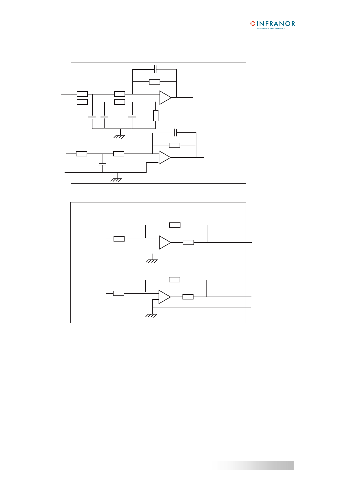
4.1 - SPECIFICATION OF THE ANALOG INPUTS / OUTPUTS
22 nF
20 KΩ
SMT-BD2
X4-17 (CV+)
X4-16 (CV-)
X4-3 (ILIM)
X4-15 (AGND)
10 KΩ
10 KΩ
10 nF
10 KΩ
10 nF
10 KΩ
10 KΩ
10 nF
10 KΩ
10 KΩ
10 KΩ
22 nF
-
+
20 KΩ
20 KΩ
+
20 KΩ
-
+
20 KΩ
-
+
22 nF
SMT-BD2
1 KΩ
X4-10 (ANout1)
1 KΩ
X4-2 (ANout2)
X4-11 (AGND)
22
Chapter 3 – Inputs-outputs

SMT-BD2
4.2 - SPECIFICATION OF THE LOGIC INPUTS / OUTPUTS
5 V
SMT-BD2
X4-1, 4, 7, 14, 20
X4-23, 24, 25
4,1 KΩ
100 KΩ
I/O
TLP281
10 nF
I/O jumper open
When the I/O jumper is open, the 0 V of the optoisolated inputs (X4 pins 23,24,25) is not connected to the 0 V of
the SMT-BD2 amplifier module (X4, pin 12).
X4-1, 4, 7, 14, 20
X4-23, 24, 25
4,1 KΩ
100 KΩ
I/O
5 V
TLP281
10 nF
SMT-BD2
I/O jumper closed
When the I/O jumper is closed, the 0 V of the optoisolated inputs (X4, pins 23, 24, 25) is connected to the 0 V of
the SMT-BD2 amplifier module (X4, pin 12).
SMT-BD2
+15 V
PRME15015
BZW04P85B
X4-5, 8, 18
X4-6, 9, 19
Chapter 3 - Inputs - Outputs
23

SMT-BD2
5 - X2 POSITION OUTPUT CONNECTOR (Sub D 25 points female)
PIN FUNCTION I / O REMARKS
1 Marker Z/ O Differential output of the encoder marker pulse (5 V, 20 mA max.)
2 Marker Z O Differential output of the encoder marker pulse
3 Channel A/ O Differential output of the encoder channel A/ (5 V, 20 mA max.)
4 Channel A O Differential output of the encoder channel A
5 Channel B/ O Differential output of the encoder channel B/ (5 V, 20 mA max.)
6 Channel B O Differential output of the encoder channel B
7 & 25 0 V O
8 to 24 reserved
The programmable encoder ouput Division ratio (Output resolution / Input resolution) is only valid for the A and B
channels. The Marker Z channel is not modified by this parameter value.
SPECIFICATION OF THE TTL ENCODER OUTPUT
SMT-BD2
Recommended receiver: 26LS32.
+5 V
X2-2, 4, 6
26LS31
X2-1, 3, 5
24
Chapter 3 – Inputs-outputs

SMT-BD2
Chapter 4 - Connections
1 - CONNECTION DIAGRAMS
- RACK POWER SUPPLY AND MOTOR CONNECTION
1.1
For the 400 VAC amplifier version, see BF-400 RACK manual.
For the 220 VAC amplifier version, see BM20A SINGLE-AXIS RACK manual or BF RACK manual.
1.2 - AMPLIFIER I/O CONNECTIONS
1.2.1 - Amplifier connections with TTL encoder & HES motor feedback
B2
B1
SMT- BD2
COD
COM
or
or
X1
10
2
11
3
9
1
5
4
B5
B4
B3
14
B5
6
B4
7
B3
15
13
B5
B4
B3
12
13
RACK
U
V
W
GND GND
+5 V
GND
U
V
W
+15 V
GND
CONTROLLER
Encoder
input
DAC
output
Logic
I/Os
GND
CV+
CV-
GND
+24 V
ENABLE
CV0
AOK
PhOK
Idyn
A
A/
B
B/
Z/
CI
Z
+24 V I/O
+24 V I/O
FC+
FC-
X2
4
3
6
5
2
1
7
X4
17
16
15
1
14
20
7
4
18
5
8
19
6
9
ENCODER
A
A/
B
B/
Z
Z/
THERMAL
U
V
W
HALL
EFFECT
SENSORS
SENSOR
MOTOR
L1
0 V
0 V I/O
Reset
25
12
13
I/O
I/O jumper open
L2
L3
GND
POWER
SUPPLY
The I/O jumper must be open for getting the X4 connector I/Os optoisolation : the I/O 0 V (X4, pins 23, 24, 25) is
disconnected from the 0 V of the SMT-BD2 amplifier module.
Chapter 4 - Connections
25

SMT-BD2
1.2.2 - Amplifier connections with Absolute single turn Sin/Cos encoder feedback
B2
B1
SMT- BD2
COD
COM
B5
B4
B3
X1
10
2
11
3
9
1
14
6
7
8
5
4
CONTROLLER
Encoder
input
GND
A
A/
B
B/
Z
Z/
X2
4
3
6
5
2
1
7
ENCODER
A
A/
B
B/
R
R/
C
C/
D
D/
+5 V
SIN/COS
THERMAL
U
V
W
SENSOR
MOTOR
POWER
SUPPLY
DAC
output
Logic
I/Os
CV+
CV-
GND
+24 V
ENABLE
CV0
AOK
PhOK
Idyn
0 V
CI
+24 V I/O
+24 V I/O
0 V I/O
FC+
FC-
Reset
X4
17
16
15
1
14
20
7
4
18
5
8
19
6
9
25
12
13
I/O
I/O jumper open
12
13
RACK
U
V
W
GND GND
L1
L2
L3
GND
The I/O jumper must be open for getting the X4 connector I/Os optoisolation : the I/O 0 V (X4, pins 23, 24, 25) is
disconnected from the 0 V of the SMT-BD2 amplifier module.
26
Chapter 4 – Connections

SMT-BD2
– CONNEXION DES E/S DU VARIATEUR EN UTILISANT LA TENSION D’ALIMENTATION +15 V SUR LE CONNECTEUR
1.2.3
X4
+15 V
FC+
FC-
ENABLE
CV0
CI
PhOK
Idyn
4,7 kOhm
4,7 kOhm
4,7kOhm
4,7 kOhm
4,7 kOhm
4,7 kOhm
4,7 kOhm
4,7 kOhm
X4
21
1
14
20
7
4
18
5
8
19
6
9
SMT- BD2
GND
RAZ
25
12
13
I/O
Pont I/O fermé
Le pont des I/O doit être fermé pour que le 0 V des E/S (X4, pins 23, 24, 25) soit connecté au 0 V du module
variateur SMT-BD2.
1.3 – CONNEXION DE LA LIAISON SERIE RS-232
Reprise de blindage sur 360°
Port série
PC
RxD 2
TxD 3
GND 5
3 TxD
2 RxD
5 GND
SMT-BD2
X5
Sub D 9 pts femelle
Sub D 9 pts mâle
Chapitre 4 – Connexions
27

SMT-BD2
2 - WIRING (according to CEI 801 and EN 55011 standards)
- GND WIRING AND GROUNDING
2.1
The reference potential is the earth (ground). Motors and sensors (encoder + HES) are grounded via their
housing. If a potential reference is existing, like a main chassis or a cabinet, with a low impedance between the
various elements, it should be used to connect ALL references to it and also connect this reference to the earth
(ground).
Long reference potential connections are suitable ONLY if these connections have an impedance < 0,1 Ω. Cables
with low potential should NEVER run in the proximity of power lines. Each conductor cable (carrying a potential)
must be shielded. Several wires in the same sleeve must be twisted and shielded.
According to the CEI 801 standard, the connectors must be metallic or metal plated and must have a 360° shield
connection.
2.2 - MOTOR AND SENSORS CABLES
Cable ends should have a metallic collar allowing a 360° shield connection.
Motor cables must be shielded to avoid common mode effects.
Encoder and HES cable must also be shielded.
2.3 - INPUT COMMAND AND SERIAL LINK CABLES
The analog input command signal CV requires a pair twisted and shielded cable. The shield must have a "360°"
connection via metallic collars at both ends. If the shield is connected by means of a pig tail, it must be connected
at one end to a 0 Volt pin of X4 on the amplifier side with a connection as short as possible.
The input command (CV) wiring must be made according to the polarity between the controller and the amplifier
(CV on "diff high" of the controller). The logic 0 Volt is directly connected to the amplifier housing. The connection
continuity is ensured by the fastening screws on the front panels. The amplifier 0 Volt and the controller 0 Volt
MUST be connected by means of a wire. The shield MUST NEVER be used as a conductor of the 0 Volt
potential.
The serial link cable must also be shielded according to the above mentioned shielding recommendations.
28
Chapter 4 – Connections

SMT-BD2
3 - 360° SHIELD ON THE CONNECTORS
RULE :
The shield must never be interrupted or corrupted over the whole cable length.
Self-sticking copper ribbon if necessary,
for increasing the shield diameter in order
to get it correctly tightened
under the clamp
W
V
U
Ground
Motor connector for
encoder and motor cables
N
W
V
L2 U
L1
Motor connector box
The cable can be soldered on the shield because the
connector box is metallic. This solution does not exactly meet
the EMC requirements but it is acceptable.
Metallic or metal plated plastic
360° shield ensured by
the tightening clamp
BF Rack
UV W
SMT-BM 20 A rack
SUB-D pin package
X
INFRANOR
amplifier
X
The fastening screws must
be tightened in order to ensure
the shield continuity on the
amplifier housing
SUB-D connector
NOTE :
When the 360° shield is made by means of a clamp it is not necessary to additionally connect a wire on the shield
connection pin of the SUB-D connector.
Chapter 4 - Connections
29
SMT-BD2
Chapter 5 - Adjustable functions
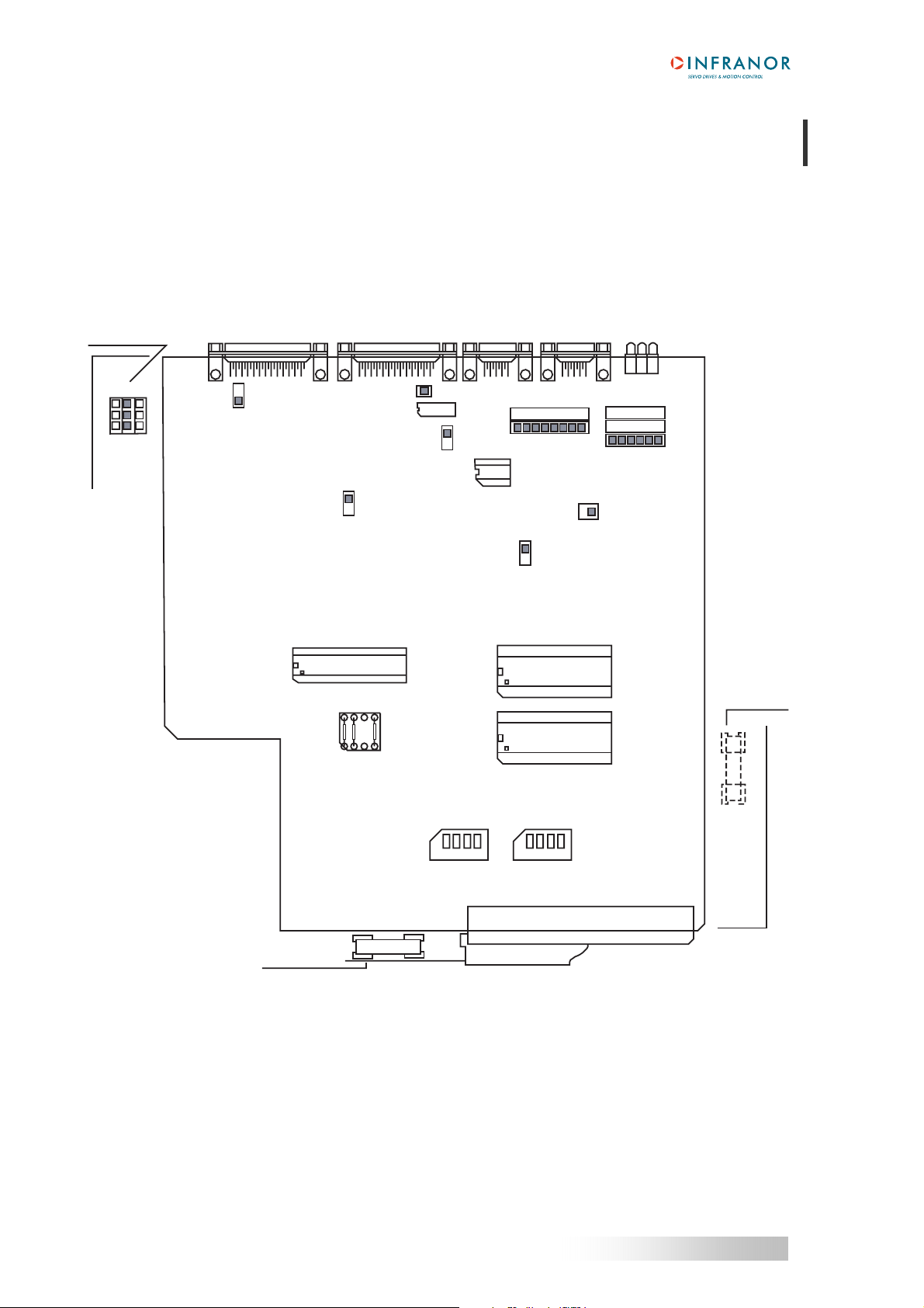
1 - HARDWARE ADJUSTMENTS
All the hardware adjustments of the SMT-BD2 amplifier module are presented on the following diagrams.
Current loops
(power board)
X4
X2 X5 X1
I/O
Inputs 0 V
B1
B3
B2
reference
Motor thermal
sensor type
16 bit ADC (option)
01656C
+5 V supply
RS-422 (option)
Serial link selection:
B=RS-232 (standard)
C=RS-422 (option)
MN
OP
PSTH
A B C D
Motor thermal
sensor adjustment
B
C
Parameters
EEPROM
"Undervolt." fault
inhibition
B2
B1
Encoder signal
JK
KL
Firmware memory
ON
COD
ZM
Encoder marker pulse
disable/enable
CT/BD2 (option)
ON
COM
Commutation signal
B5
B4
B3
Power fuse
(power board)
Only for the
AC
range
220 V
F1
30
Logic fuse
(power board)
1
234
Drive address selection
F2
PR3
1
234
PR8
For amplifier types 220/04 to 220/60 and 400/15 to 400/60 VAC range
Chapter 5 – Adjustable functions

SMT-BD2
F2
PU
CA
C14
RA
PV
CA
C14
RA
PW
F1
A
A and B OPEN: with auxiliary supply
B
A and B CLOSED: without auxiliary supply
PR3
Power board adjustment for amplifier types 220/70 A and 220/100 A
CA
C14
RA
Chapter 5 - Adjustable functions
31

SMT-BD2
Braking resistor
Braking resistor jumper
for 220/04w to 220/17w
Braking resistor jumper
for 220/30w to 220/60 w
SMT-BM 20 A single-axis rack: Braking resistor jumper closed.
BF-rack: Braking resistor jumper open.
NOTE: This braking resistor system selection is only available on « w » referenced amplifiers.
Braking system selection on SMT-BD2-220/04w to 220/60w
32
Chapter 5 – Adjustable functions

SMT-BD2
2 – ADJUSTABLE PARAMETERS
The SMT-BD2 serial link connector (X5) must be connected to the serial interface of a PC for the parameter
setting operation. The Visual Drive Setup software, which is IBM-PC compatible with the WINDOWS® operating
system, allows the clear display and easy modification of all amplifier parameters.
Please see Web site www.infranor.fr
Minimum requirements for the PC
Processor : Pentium
Operating system : WINDOWS 95/98, WINDOWS NT
Graphics adapter : Windows compatible, colour
SVGA with resolution 800x600 or 1024x768
Drives : 3.5” disk drive
hard disk with 6 MB free space
Main memory : at least 8 MB
Interface : One free serial interface (COM1, COM2, COM3 or COM4)
for downloading the Visual Drive Setup software.
Chapter 5 - Adjustable functions
33

SMT-BD2
Chapter 6 - Commissioning
1 - CHECKING THE AMPLIFIER CONFIGURATION
- STANDARD AMPLIFIER CONFIGURATION
1.1
The standard SMT-BD2 amplifier configuration is given below. See chapter 5, section 1 "Hardware
adjustments" for the jumpers location.
* Inputs 0 V reference jumper I/O is open (optoisolated inputs)
* Current loops adjustment jumpers in position B2 (medium gain)
* Motor temperature sensor jumper in position MN (PTC sensor type)
* Undervolt fault inhibition jumper in position JK ("Undervolt." fault enabled)
* Serial link communication jumper in position B (RS-232 protocol)
* Drive address selection jumpers in position OFF (address 0 selected)
* Encoder signal jumpers COD in position B1 (TTL incremental encoder configuration)
* Encoder marker pulse jumper in position ZM (encoder marker pulse enabled)
* Commutation signal jumpers COM in position B3 (incremental encoder configuration without HES)
During the machine adjustments, some drive connection or parameter setting errors may involve
dangerous axis movements. It is the user's responsibility to take all necessary steps in order to
!
reduce the risk due to uncontrolled axis movements during the operator's presence in the concerned
area.
1. 2 - ENCODER CONFIGURATION
If the motor is equipped with a "TTL incremental encoder", select the following COD and COM jumpers setting.
COD
B2
B1
If the motor is equipped with a "Sin/Cos incremental encoder", select the following COD and COM jumpers
setting.
COD
B2
B1
If the motor is equipped with an "Absolute single turn Sin/Cos encoder" (Heidenhain ERN 1085 or compatible),
select the following COD and COM jumpers setting.
COD
B2
B1
COM
COM
COM
B5
B4
B3
B5
B5
B4
B3
B4
B3
34
Chapter 6 – Commissioning

SMT-BD2
1. 3 - HALL EFFECT SENSORS CONFIGURATION
If the motor is equipped with Hall Effect Sensors devices (HES), select the following COM jumpers setting
according to the HES type (60° or 120°).
COM
B5
B4
B3
COM
B5
B4
B3
60° HES type
120° HES type
If the motor is not equipped with Hall Effect Sensors devices, the following COM jumpers setting must be
selected. In this case a motor phasing procedure must be executed at each amplifier power up.
COM
B5
B4
B3
1. 4 - MOTOR THERMAL SENSOR CONFIGURATION
Select the right MN or OP jumper setting according to the motor thermal sensor type (PTC or NTC).
1.4.1 - PTC thermal sensor
On motors equipped with a PTC thermal sensor (triggering on high impedance), the amplifier configuration is the
following: MN jumper closed and OP jumper open. The triggering threshold adjustment for the PTC thermal
sensor is made by means of the PSTH components, as described below : PSTH-D = 14,3 kΩ; PSTH-B = 28 kΩ;
PSTH-A = 3 x RPTC (120°C) in kΩ. RPTC (120°C) = ohmic value of the PTC thermal sensor resistor at 120°C;
the default adjustment is RPTC (120°C) # 3 kΩ with PSTH-A = 10 kΩ.
1.4.2 - NTC thermal sensor
On motors equipped with a NTC thermal sensor (triggering on low impedance), the amplifier configuration is the
following: OP jumper closed and MN jumper open. The triggering threshold adjustment for the NTC thermal
sensor is made by means of the PSTH components, as described below: PSTH-D = 14,3 kΩ; PSTH-B = 28 kΩ;
PSTH-A = 3 x RNTC (120°C) in kΩ. RNTC (120°C) = ohmic value of the NTC thermal sensor resistor at 120°C;
the default adjustment is RNTC (120°C) # 3 kΩ with PSTH-A = 10 kΩ.
Chapter 6 - Commissioning
35

SMT-BD2
1.5 - CURRENT LOOPS ADJUSTMENTS
1.5.1 - Current loops adjustments for the 400 VAC amplifier version
Select the right current loops jumpers setting (B1, B2 or B3 position) according to motor and amplifier
specifications.
For the 400VAC version of the BL MAVILOR motor series, the current loops adjustments are made according to
following selection table.
AMPLIFIER
MOTOR
BL 113 B2
BL 114 B2
BL 115 B2 B1
BL 141 B1 B1
BL 142 B2 B1
BL 143 B1 B1 B1
BL 144 B1 B1 B1
BL 191 B3 B3
BL 192 B3 B3
For other motors the adjustment of the current loops according to the amplifier current rating and to the
inductance between the motor terminals is made as follows:
15 A and 30 A amplifier current ratings
Calculation of G = 0.8 x Amplifier current rating (A) x Inductance between phases (mH),
If G < 60, current loop jumpers (x3) on B3 position,
If 60 < G < 100, current loop jumpers (x3) on B2 position,
If G > 100, current loop jumpers (x3) on B1 position.
45 A and 60 A amplifier current ratings
Calculation of G = 0.8 x Amplifier current rating (A) x Inductance between phases (mH),
If G < 100, current loop jumpers (x3) on B3 position,
If 100 < G < 250, current loop jumpers (x3) on B2 position,
If G > 250, current loop jumpers (x3) on B1 position.
15 A 30 A 45 A 60A
36
Chapter 6 – Commissioning

SMT-BD2
1.5.2 - Current loops adjustments for the 220 VAC amplifier version
Select the right current loops jumpers setting (B1, B2 or B3 position) according to motor and amplifier
specifications.
For the BL and MA MAVILOR motor series, the current loops adjustments are made according to following
selection table.
AMPLIFIER
MOTOR
MA 3 B1
MA 6 B1 B1
MA 10 B2 B1 B1 B1
MA 20 B2 B1 B1 B1 B1 B1
MA 30 B2 B2 B2 B1 B1
MA 45 B2 B2 B1 B1 B1
MA 55 B2 B2 B2 B1
BL 55-3 B1
BL 55-5 B1
BL 71 B2
BL 72 B2 B1 B1
BL 73 B2 B1 B1
BL 74 B2 B1 B1
BL 111 B1 B1
BL 112 B2 B2 B1 B2
BL 113 B3 B3 B2 B2 B2
BL 114 B3 B3 B2 B2
BL 115 B3 B3 B2 B2 B2
BL 141 B2 B2 B2 B1 B1
BL 142 B3 B3 B2 B2 B1
BL 143 B3 B2 B2 B1 B1 B1
BL 144 B2 B2 B2 B1 B1 B1
For other motors the adjustment of the current loops according to the amplifier current rating and to the
inductance between the motor terminals is made as follows:
4 A, 8 A, 12 A and 17 A amplifier current ratings
Calculation of G = 1,4 x Amplifier current rating (A) x Inductance between phases (mH),
If G < 60, current loop jumpers (x3) on B3 position,
If 60 < G < 100, current loop jumpers (x3) on B2 position,
If G > 100, current loop jumpers (x3) on B1 position.
30 A, 45 A, 60 A, 70 A and 100 A amplifier current ratings
Calculation of G = 1,4 x Amplifier current rating (A) x Inductance between phases (mH),
If G < 100, current loop jumpers (x3) on B3 position,
If 100 < G < 250, current loop jumpers (x3) on B2 position,
If G > 250, current loop jumpers (x3) on B1 position.
4 A 8 A 12 A 17 A 30 A 45 A 60 A 70 A 100 A
Chapter 6 - Commissioning
37

SMT-BD2
2 - PUTTING INTO OPERATION
The "Enable" input must be open and the analog input command CV open or short-circuited (X4 connector can be
disconnected).
Test the auxiliary supply voltage :
Rated value = 230 Vrms single-phase.
Maximum value (must never be exceeded) = 260 Vrms, all mains variation tolerances included.
Switch on the auxillary supply. The green ON Led must be lit and the UNDERVOLT error must be displayed.
Test the power supply voltage :
- For the 220 VAC amplifier version: Rated value = 230 Vrms between phases.
Maximum value (must never be exceeded) = 260 Vrms, all mains variation tolerances included.
- For the 400 VAC amplifier version: Rated value = 400 Vrms between phases.
Maximum value (must never be exceeded) = 480 Vrms, all mains variation tolerances included.
Switch on the power supply. The UNDERVOLT error Leds must be unlit. The braking resistor must remain cold.
!
Check that the amplifiers front panel screws are correctly fastened on the rack.
CAUTION ! This resistor is under high voltage
3 - AMPLIFIER COMMISSIONING AND ADJUSTMENT
- AMPLIFIER SETUP
3.1
Connect the encoder feedback cable between the motor and the amplifier X1 connector.
Connect the X4 command connector : the Enable input must be open, the FC+ and FC- limit switches inputs must
be connected and closed, and the analog input command CV must be open or short-circuited.
Connect the serial link RS 232 between the PC and the amplifier X5 connector.
Switch on the PC and the monitor and then start the WINDOWS® interface.
Start the Visual Drive Setup software installation and follow the instructions.
Turn on the SMT-BD2 amplifier and start the Visual Drive Setup software.
If the message "No serial communication found" appears on the screen, click on OK and check following points
before connecting again the Visual Drive Setup software:
- the amplifier is on (green LED ON must be lit),
- the amplifier and the PC are correctly connected via the RS 232 link,
- the software configuration (Com. port and Baudrate) is correct.
The Connect and Disconnect commands in the Setup menu allow to change the serial link connection from one
amplifier to the other without leaving the Visual Drive Setup software.
!
The amplifier command cables (input command, serial link, encoder, HES) as well as the power
cables must be connected and disconnected with the amplifier turned off.
38
Chapter 6 – Commissioning

SMT-BD2
3.2 - MOTOR HALL EFFECT SENSORS ADJUSTMENT
If the motor is using Hall Effect Sensors, check that the COM jumpers setting is correct according to the motor
HES type (60° or 120°).
Check that the ENABLE input is disabled and the amplifier turned on.
If the “ HES ” error is displayed, turn off the amplifier and check the following points before turning it on again:
♦ The HES are correctly wired on the amplifier X1 connector (if 60° type HES are used, check the different
HES signals wiring combinations to find the right wiring order).
♦ The commutation signal jumpers COM are correctly set according to the HES type.
♦ The HES supply voltage value is correct.
Move the motor manually over one revolution, or one pole pitch for a linear motor.
If the “ HES ” error is displayed turn off the amplifier and check the following points before turning it on again:
♦ The HES are correctly wired on the amplifier X1 connector (if 60° type HES are used, check the different
HES signals wiring combinations to find the right wiring order).
♦ The commutation signal jumpers COM are correctly set according to the HES type.
♦ The HES supply voltage value is correct.
♦ The Motor encoder resolution parameter value is correct.
If the motor HES are not working correctly, select the following COM jumpers setting to run the motor without the
HES devices.
COM
In this case a motor phasing procedure must be executed at each amplifier power up.
B5
B4
B3
3.3 - ABSOLUTE SINGLE TURN SIN/COS ENCODER ADJUSTMENT
If the motor is using an absolute single turn Sin/Cos encoder (Heidenhain ERN 1085 or compatible), check that
the COD and COM jumpers setting are correct.
Check that the ENABLE input is disabled and the amplifier turned on, and move the motor manually over one
revolution.
If the “ HES ” error is displayed, turn off the amplifier and check the following points before turning it on again:
♦ The Sin/Cos encoder commutation channels are correctly wired on the amplifier X1 connector.
♦ The commutation signal jumpers COM are correctly set.
♦ The Sin/Cos encoder supply voltage value is correct.
♦ The Motor encoder resolution parameter value is correct.
Chapter 6 - Commissioning
39

SMT-BD2
3.4 - AMPLIFIER PARAMETER SETTING
Select Software control mode and switch on the Off position.
Select the motor to be used in the Motor list and check the Motor encoder resolution value, the Speed limit
and the Current limits according to the motor and amplifier specifications.
Select Fusing mode for the I
If the “incremental encoder" configuration without HES is selected, check that the free motor
!
If the motor used is not on the Motor list , proceed as described below :
♦ Enter the servo motor Encoder resolution value.
♦ Adjust the Speed limit according to the motor and encoder specifications.
♦ Adjust the Current limits according to the motor and amplifier specifications.
♦ Uncouple the motor from the mechanical load and check that the free motor movement over 1 revolution, or
1 pole pitch for linear motors, is not dangerous for the operator. Then execute the Auto-phasing procedure.
♦ Calculate the Current phase lead value (this parameter is especially useful for motors with a low inductance
and running at high speeds).
Select the Encoder output resolution.
!
In case of loud noise in the motor at standstill and when running, check the rigidity of the transmission between
motor and load (backlashes and elasticities in gears and couplings). If necessary, renew the Auto-tuning
procedure by selecting a lower bandwidth (Bandwidth = Medium or Low). If the problem remains, renew the
Auto-tuning procedure by activating the Antiresonance filter.
!
Test the motor running in both directions with a low digital speed reference value. If required, adjust with more
accuracy the speed loop response stability by means of the Stability gain buttons or by means of the adjustable
gain values.
Short-circuit the "CV" input of the X4 connector or enter a zero speed input command in the NC, if you want to
compensate the offset of the whole amplifier + NC system. Then execute the Offset compensation procedure or
activate the Offset button on the amplifier front panel.
movement over 1 revolution, or 1 pole pitch for linear motors, is not dangerous for the operator. Then
execute the motor phasing procedure (see section 3.7 of this chapter).
Couple the motor to the load ; in the case of an axis with an unbalanced load (constant torque due to
the gravity effect on a vertical axis), see paragraph 3.5 of this chapter. Check that the free motor
movement over 1 revolution, or 1 pole pitch for linear motors, is not dangerous for the operator and
the machine. Select the most apropriate filter and bandwidth; then execute the Auto-tuning
procedure.
The Auto-tuning procedure should be executed in Software control mode and Off position
selected. If the Auto-tuning procedure must be executed with the drive controlled by the analog input
command CV, the value of the analog input command MUST be set at 0 Volt. It is the user's
responsibility to take all necessary steps in order to reduce the risk due to uncontrolled axis
movements during the Auto-tuning procedure.
2
t protection during all commissioning phases.
3.5 - AMPLIFIER AUTO-TUNING WITH AN UNBALANCED LOAD
!
Select Software control mode and switch on the OFF position.
Execute a first Auto-tuning procedure with the motor uncoupled from its mechanical load in order to initialize the
gain values before coupling the motor to the load again.
Select the current limitation in Limiting mode and select a PI or PI
and the motor brake are correctly operating before starting the Auto-tuning procedure.
40
In the case of an axis with an unbalanced load (constant torque due to the gravity effect on a vertical
axis), the “incremental encoder ” configuration without HES is not valid because the motor phasing
procedure at power up cannot be executed.
2
speed regulator. Check that the limit switches
Chapter 6 – Commissioning

SMT-BD2
Move the shaft with a low digital speed reference value up to a maintaining position (far enough from the axis limit
switches) where a free movement over 1 revolution, or 1 pole pitch for linear motors, is not dangerous for operator
and machine. Then execute the Auto-tuning procedure with the motor enabled at its maintaining position (digital
speed reference input set at 0). In case of loud noise in the motor at standstill and when running, check the rigidity
of the transmission between motor and load (backlashes and elasticities in gears and couplings). If necessary,
renew the Auto-tuning procedure by selecting a lower bandwidth (Bandwidth = Medium or Low). If the problem
remains, renew the Auto-tuning procedure by activating the Antiresonance filter.
During the Auto-tuning procedure execution with an unbalanced load (constant torque due to the gravity
effect on a vertical axis), a wrong operation may involve dangerous axis movements. It is the user's
!
responsibility to take all necessary steps in order to reduce the risk due to uncontrolled axis movements
during the operator's presence in the concerned area.
Test the motor running in both directions with a low digital speed reference value. If required, adjust with more
accuracy the speed loop response stability by means of the Stability gain buttons or by means of the adjustable
gain values.
Go back to the motor standstill position before switching on the OFF position.
3.6 - SAVING OF THE AMPLIFIER PARAMETERS
Save all parameters in the amplifier EEPROM by means of the Save parameter to EEPROM procedure.
3.7 - MOTOR PHASING AT POWER UP
In the “incremental encoder ” configuration without HES, the motor phasing procedure must be executed
according to the following diagram at each amplifier power up:
AMP. READY
X4-18, 19
POWER
READY
ENABLE
X4-20
CV0
X4-7
PHASING OK
X4-5, 6
Power up
End power up
Ready
Start phasing
Phasing
End phasing
Stopped
Start running
Running
In the case of an axis with an unbalanced load (constant torque due to the gravity effect on a vertical
axis), the motor phasing procedure is not valid. The motor must be equipped with an incremental
!
encoder + HES or an absolute single-turn Sin/Cos encoder.
Chapter 6 - Commissioning
41

SMT-BD2
3.8 – PARAMETERS ADJUSTMENT TO A LINEAR MOTOR
The Motor encoder resolution parameter is calculated as described below:
S N S N S N
Motor magnets
Motor encoder resolution = 1000 x
!
The motor Maximum speed parameter value in rpm is calculated according to following formula:
Maximum speed (rpm) = 60 x x Maximum motor speed (m/s)
The linear speed value in m/s is calculated according to following formula:
Linear speed (m/s) = x X
1 encoder signal pitch = 4 counting increments
Motor pole pitch (mm)
Motor speed (rpm)
60
Pole pitch
Motor pole pitch (mm)
Encoder signal pitch (µm)
1000
Motor pole pitch (mm)
1000
42
Chapter 6 – Commissioning

SMT-BD2
Chapter 7 – Fault finding
1 - SYSTEM FAULT
If the red SYS led is lit when the amplifier is on, the logic board is off duty.
Check that the EPROM firmware memory is correctly plugged on the amplifier.
Check for the possible presence of any conducting dust that may involve short-circuits on the amplifier logic
board.
2 - STORED FAULTS
If a fault occurs on the amplifier, it can generate the detection of several other faults which are only a
consequence of the original one. In order to simplify the diagnostic and the maintainance, the faults are displayed
and processed with the priority described below. For safety reasons, the power must be turned off before
cancelling some faults that require the handling of the amplifier or the connectors.
2.1 - "BUSY" FAULT
If the BUSY fault is continuously displayed after power on, the auto-test procedure has failed and the control
board is not operating correctly.
If the BUSY fault is continuously displayed after the starting of the motor phasing procedure by CVO at power
up (“incremental encoder ” configuration without HES) , the procedure has failed because of an external
cause and the calculated phase value is wrong. Check that the Motor encoder resolution parameter value is
correct. Check that the Motor parameters (Pole pairs and Phase order) values are correct. Check that the
ENABLE input is activated. Check that the limit switches inputs are not activated. Check that the motor is not
locked and the shaft movement is free during the procedure execution.
If the BUSY fault is continuously displayed after the execution of the Auto-phasing procedure, the procedure
has failed because of an external cause and the calculated parameters are wrong. Check that the Motor
encoder resolution parameter value is correct. Check that the ENABLE input is activated. Check that the
limit switches inputs are not activated . Check that the motor is unloaded and the shaft movement is free
during the procedure execution.
If the BUSY fault is continuously displayed after the execution of the Auto-tuning procedure, the procedure
has failed because of an external cause and the calculated parameters are wrong. Check that the ENABLE
input is activated. Check that the limit switches inputs are not activated. Check that the motor shaft
movement is free during the procedure execution.
If the BUSY fault is continuously displayed after the execution of the Offset compensation procedure, the
offset is exceeding +/- 0.3 Volts. Check for the voltage value on the analog speed input command CV during
the procedure execution. Check that the input command wiring between controller and amplifier answers the
requirements of chapter 4 (CV at diff. low of the NC and 0 Volt cable).
If the BUSY fault is continuously displayed after the execution of the Cogging torque acquisition procedure
(for rotating motors), the procedure has failed because of an external cause and the cogging acquisition is not
valid. Check that the ENABLE input is activated. Check that the CI and CV0 inputs are not activated. Check
that the limit switches inputs are not activated. Check that the encoder is providing one marker pulse per
motor revolution. Check that the motor is unloaded and the shaft movement is free during the procedure
execution. Check that the motor current value corresponding to the cogging torque effect is lower than 5% of
the amplifier current rating.
If the BUSY fault is continuously displayed after the execution of the Linear Cogging acquisition procedure
(for linear motors), the procedure has failed because of an external cause and the cogging acquisition is not
valid. Check that the ENABLE input is activated. Check that the CI and CV0 inputs are not activated. Check
that the positive and negative motor travel limit switches are operating correctly. Check that the encoder is
providing one marker pulse over the entire motor travel. Check that the motor is unloaded and the
displacement is free during the procedure execution. Check that the motor current value corresponding to the
cogging force effect is lower than 5% of the amplifier current rating. Check that the motor travel distance (from
the negative to the positive limit switch) is less than 4000000 encoder counting increments.
Chapter 7 - Fault finding
43

SMT-BD2
2.2 - "EEPROM" FAULT
Check for the presence of the EEPROM and check its correct orientation and mounting.
If the fault remains, the EEPROM is not correctly initialized (CHECKSUM error) or is not compatible with the
amplifier software. In this case, if the EEPROM fault is reset and if then the Save parameters to EEPROM
procedure is executed, the EEPROM is automatically reinitialized with the amplifier default parameters.
2.3 - "°C MOTOR" FAULT
If the fault occurs when starting the amplifier:
- Check the configuration of the MN and OP jumpers with regard to the type of thermal sensor used in the
motor.
- Check the connection between thermal sensor and amplifier on the front panel connector X1.
If the fault occurs during the operation:
- Check the motor temperature value and look for the reason of the motor overheating (mechanical
overload, duty cycle too high, ...)
2.4 - "UNDERVOLT." FAULT
If the fault occurs when starting the amplifier:
- Check that the power supply is on.
If the fault occurs during the operation:
- Check that the power supply connections are correct
- Check that the power supply voltage value is correct
2.5 - "°C AMPLIFIER" FAULT
Check that the fan and the heatsink configurations are correct with regard of the required rated current (see
current table, Chapter 2, section 1).
Remark : This fault is only valid on amplifiers with current ratings 220/70 and 220/100.
2.6 - "POWER STAGE" FAULT
If the fault occurs when starting the amplifier:
- Check the DC bus voltage and the terminal voltage of the power transformer secundary :
For the 220VAC version of the amplifier DC bus < 370 VDC and V secundary < 260 VAC
For the 400VAC version of the amplifier DC bus < 800 VDC and V secundary < 480 VAC
If the fault occurs during the operation:
- Check the braking system operation during the deceleration phases is correct,
- Check the sizing of the braking resistor with regard to the deceleration phases.
- Check for no short-circuit in the motor wiring and at the motor terminals.
- For amplifiers with 220/04 to 220/60 current ratings and 400 VAC range, check that the fan and the
heatsink configuration is correct with regard to the required rated current (see current table, Chapter 2,
section 1).
2.7 - "HES" FAULT
For the "incremental encoder & HES" configuration:
Check that the HES are correctly wired on the amplifier X1 connector (with 60° type HES you must check the
different wiring combinations to found the right wiring order).
Check that the commutation signal jumpers COM are correctly set according to the HES type.
Check for the correct HES supply voltage value.
Check for the correct Motor encoder resolution parameter value.
Check that the HES-amplifier-motor ground connections and shield answer the requirements of chapter 4.
For the "Absolute single turn Sin/Cos encoder" configuration:
44
Chapter 7 – Fault finding

SMT-BD2
Check that the Sin/Cos encoder commutation channels are correctly wired on the amplifier X1 connector.
Check that the commutation signal jumpers COM are correctly set.
Check for the correct Sin/Cos encoder supply voltage value.
Check for the correct Sin/Cos encoder C channel and D channel signal amplitude value.
Check that the Motor encoder resolution parameter value is correct.
Check that the encoder-amplifier-motor ground connections and shield answer the requirements of
chapter 4.
2.8 - "ENCODER" FAULT
For the “incremental encoder" configuration:
Check the encoder supply connection on the amplifier connector X1.
Check that the encoder signal jumpers COD are correctly set.
Check the encoder A channel, B channel and marker pulse connections on the amplifier connector X1.
If the motor encoder is not providing a marker pulse channel output, the amplifier marker pulse channel must be
disabled in order to cancel the "Encoder" fault. In this case the encoder marker pulse jumper ZM must be set in
the disabled position as described below.
Encoder marker pulse enabled
For the “ Absolute single turn Sin/Cos encoder” configuration:
Check the encoder supply connection on the amplifier connector X1.
Check that the encoder signal jumpers COD are correctly set.
Check the encoder A channel and B channel connections on the amplifier connector X1.
When the amplifier marker pulse channel input is disabled, the encoder counting protection is disabled
(see section 2.9 "Counting" fault). In this case an incorrect encoder pulses counting can involve
uncontrolled motor movements that may be dangerous for operator and machine.
Encoder marker pulse disabled
ZM
Chapter 7 - Fault finding
45

SMT-BD2
2.9 - "COUNTING" FAULT
For the "TTL incermental encoder" configuration:
Check that the encoder signal jumpers COD are correctly set (position B1).
Check for the correct encoder supply voltage value
Check for the correct encoder-amplifier-motor ground and shield connections with regard to the
recommendations of chapter 4.
Check for the correct encoder A channel, B channel and Z marker signal waveforms
A
A
A/
A/
B
B
B/
B/
Z
Z/
Forward direction
Z
Z/
Reverse direction
Check that the following condition are answered for taking into account the maximum value of the encoder
pulse frequency at the maximum motor speed value :
Max. motor speed (rpm) < 60 x 10
6
/ Number of encoder pulses per revolution
Max. motor speed (rpm) < 60 x Encoder pulse frequency limit (Hz) / Number of encoder pulses per revolution
Check that the Motor encoder resolution parameter value is correct.
Check that the number of encoder pulses between two successive Z marker pulses is an entire multiple of the
Motor encoder resolution value. If this condition is not fulfilled, the encoder counting protection must be
disabled in order to cancel the "Counting" fault. The encoder counting protection can be disabled by disabling
the encoder marker pulse by means of the ZM jumper (see section 2.8 "Encoder fault").
The encoder counting protection is checking that the encoder pulses count value between two
successive Z marker pulses is an entire multiple of the Motor encoder resolution value. When the
encoder counting protection has been disabled, the amplifier is only checking that the encoder pulses
frequency is lower than 1.5 times the maximum encoder frequency. The maximum encoder frequency
is calculated into the amplifier according to the Motor encoder resolution parameter value and the
Maximum speed parameter value. In this case, encoder pulse noise at a frequency lower than 1.5
times the maximum encoder frequency may involve uncontrolled motor movements that may be
dangerous for operator and machine.
46
Chapter 7 – Fault finding

SMT-BD2
For the Sin/Cos encoder" configuration:
Check that the encoder signal jumpers COD are correctly set (position B2)
Check for the correct encoder supply voltage value
Check for the correct encoder-amplifier-motor ground and shield connections with regard to the
recommendations of chapter 4.
Check for the correct encoder A channel, B channel and R reference signal waveforms.
A
A/
B
B/
A
A/
B
B/
R
R/
Forward direction Reverse direction
Check for the correct Motor encoder resolution parameter value.
Check that the number of encoder pulses between two successive R reference signals is an entire multiple of
the Motor encoder resolution value. If this condition is not fulfilled, the encoder counting protection must be
disabled in order to cancel the "Counting" fault. The encoder counting protection can be inhibited by disabling
the encoder reference channel by means of the ZM jumper (see section 2.8 "Encoder fault").
2.10 - "I
Check the rated current value required with regard to the current table (see chapter 2, section 1).
Check the amplifier rated current defined in the Rated current parameter with regard to the current required
The encoder counting protection is checking that the encoder pulse count value between two
successive R
encoder counting protection has been disabled, the amplifier is only checking that the encoder pulse
frequency is lower than 1.5 times the maximum encoder frequency. The maximum encoder frequency
is calculated into the amplifier according to the Motor encoder resolution parameter value and the
Maximum speed parameter value. In this case, encoder pulse noise at a frequency lower than 1.5
times the maximum encoder frequency can involve uncontrolled motor movements that may be
dangerous for operator and machine.
2
T" FAULT
for the operation cycle.
reference signals is an entire multiple of the Motor encoder resolution value. When the
R
R/
2.11 - "TRACKING" FAULT
Check that the Speed following error threshold parameter value is compatible with the required amplifier
operating cycle (speed profile and speed loop adjustments). If necessary, increase the Speed following error
threshold parameter value.
2.12 - "ADC" FAULT
On SMT-BD2/b amplifiers equipped with the 16 bit ADC option, check for the correct orientation and the
correct mounting of the 16 bit ADC component.
Check that the input command wiring between controller and amplifier corresponds to the recommendations
of chapter 4, and repeat the Offset compensation procedure.
If the fault still remains, the amplifier control board is not operating correctly.
Chapter 7 - Fault finding
47

SMT-BD2
3 - OPERATING PROBLEMS
- MOTOR SUPPLIED, BUT NO TORQUE
3.1
Check the Maximum current and Rated current parameters.
Check that the current limitation input (X4 pin 3) is not activated.
Check that the amplifier is not operating in torque mode (X4 pin 4 active) with zero input command or with
CV0 input activated.
3.2 - MOTOR DOES NOT MOVE
Check that the amplifier is on.
Check that the power supply is on.
Check the amplifier fuses (F1 and F2) and the motor connection.
Check the wiring of the signals FC+, FC- and ENABLE.
3.3 - SHAFT LOCKED, ERATIC OSCILLATIONS OR ROTATION AT MAXIMUM SPEED
Check that the Pulse input mode is disabled in the Advanced functions menu.
Check the encoder wiring on the X1 connector and the mechanical mounting of the encoder on the motor.
Check the value of the Motor parameters parameter in the Advanced Functions menu and repeat the
Auto-phasing procedure, with unloaded motor.
3.4 - DISCONTINUOUS MOTOR ROTATION WITH ZERO TORQUE POSITIONS
Check the connection of the 3 phase cables between motor and amplifier.
3.5 - MOTOR DRIFT WITH ANALOG INPUT COMMAND AT ZERO SPEED
Check that the input command wiring between the controller and the amplifier corresponds to the
recommendations of chapter 4 (CV at diff. low of the NC and 0 Volt cable).
Check the offset compensation and, if necessary, execute the Offset compensation procedure.
3.6 - LOUD CRACKLING NOISE IN THE MOTOR AT STANDSTILL
Check that the motor-amplifier-controller ground connections correspond to the recommendations of chapter
4.
Check that the speed input command wiring between controller and amplifier corresponds to the
recommendations of chapter 4 and check the shield connection of the encoder cable.
3.7 - LOUD NOISE IN THE MOTOR AT STANDSTILL AND WHEN RUNNING
Check the rigidity of the mechanical transmission chain between motor and load (backlash and elasticity in
the gearboxes and couplings).
Execute the Auto-tuning procedure again by choosing a lower bandwidth (Medium or Low).
If the problem remains, renew the Auto-tuning procedure by activating the Antiresonance filter.
3.8 - POSITION CONTROL NOT POSSIBLE WITH THE NC
Check for the presence of the A, B and Z signals on the amplifier X2 connector by turning manually the motor
shaft and check the wiring between NC and amplifier.
Check for the correct Maximum speed and Encoder output resolution parameters.
Check for the counting direction of the NC with regard to the sign of the speed input command. If there is a
reversal, use the function Reverse Movement to get a correct operation.
48
Chapter 7 – Fault finding

SMT-BD2
4 - SERVICE AND MAINTENANCE
When exchanging an amplifier on a machine, proceed as follows:
- Check that the new amplifier has the same hardware configuration as the old one,
- Plug in the parameter EEPROM (or a copy of it) of the old amplifier on the new one,
- Apply a zero speed input command and start the offset compensation procedure by means of the Offset button
on the amplifier front panel.
The new amplifier is configurated like the old one.
Chapter 7 - Fault finding
49

SMT-BD2
Chapter 8 - Appendix
1 - USE OF THE LIMIT SWITCHES & "CVO" INPUTS
During the amplifier operation in speed mode (CI input inactive) the enabling of the CV0 input immediately stops
the motor. The motor is decelerating according to the Accel/decel time parameter value. The motor is maintained
at standstill while the CV0 input is activated. During the amplifier operation in torque mode (CI input activated) the
enabling of the CV0 input sets the current reference at 0. The current reference is maintained at 0 while the CV0
input is activated.
During the amplifier operation in speed mode (CI input inactive) or in torque mode (CI input active), the enabling
of the FC+ limit switch stops any motor displacement in the positive direction and the enabling of the FC- limit
switch stops any motor displacement in the negative direction. The motor is decelerating with the amplifier
Maximum current value in order to get the shortest possible braking time.
!
2 - USE OF THE "AMP. READY" & "POWER READY" OUTPUTS
When an amplifier fault is released, the AMP. READY output is immediatly disabled (contact is open). After
elimination of the error source, the amplifier can be reset via pins 12 and 13 of the X4 connector.
If the position initialization reference must be kept when a stored fault is released on the amplifier and the power
supply turned off, it is necessary to have an auxiliary supply for the logic board which is independent from the
power supply. In this case, the JK and KL jumpers of the logic board allow to inhibit or to release the "Undervolt."
fault when the amplifier is turned on.
JK jumper closed and KL jumper open configuration :
If the auxiliary supply is turned on before the main power supply, the "Undervolt." fault is displayed and
can hide a fault of lower priority. The AMP READY and POWER READY outputs are both inactive
(contact is open) until the power supply in on.
JK jumper open and KL jumper closed configuration :
The "Undervolt." fault is inhibited when turning on the auxiliary supply before switching on the main
power supply. The AMP READY output is then active and POWER READY remains inactive (contact
open) until the main power supply is on.
Positive and negative directions depend on the encoder wiring and on the motor wiring. So, before
mounting and wiring the limit switches, it is recommended to find the positive and negative directions
of the motor.
3 - SPEED FOLLOWING ERROR PROTECTION
During the amplifier operation in speed mode (ENABLE input active and CI input inactive), when the speed
controller error reaches the following error threshold value, the “Tracking” fault is released and the amplifier is
disabled. The Speed following error threshold parameter value must be adjusted at its minimum value
according to the operating cycle in order to detect any uncontrolled motor movements that may be dangerous for
operator and machine.
50
Speed following error protection is inactive during the Auto-phasing and the Auto-tuning
procedures. When the amplifier is operating in torque mode (CI input active), the speed following
!
error protection is also inactive.
Chapter 8 – Appendix

SMT-BD2
4 – I2t PROTECTION
– CURRENT LIMITATION IN FUSING MODE
4.1
When the amplifier RMS current (I
the I2t error display is blinking on the amplifier front panel. If the RMS current (I2t) has not dropped below 85 % of
the Rated current within 1 second, the I
and the blinking I2t error display are both cancelled).
When the amplifier RMS current (I
current at this value.
The amplifier current limitation diagram in an extreme case (motor overload or locked shaft) is shown below.
Maximum current
Rated current
2
t) reaches 85 % of the Rated current, the Idyn signal output is activated and
2
t fault is released and the amplifier is disabled (otherwise, the Idyn signal
2
t) reaches the Rated current value, the I2t protection limits the amplifier
Amplifier current
t1 = Idyn signal activation
t2 = current limitation
2
t3 = I
t fault
1 second
Time
t0
t1 t2 t3
The maximum current duration before the release of the Idyn signal depends on the value of the Rated current
and Maximum current parameters. This value is calculated as follows:
T dyn (second) = t1 - t0 = 3.3 x [ Rated current (%) / Maximum current (%) ] 2
The maximum current duration before the limitation at the rated current also depends on the value of the Rated
current and Maximum current parameters. This value is calculated as follows:
T max (second) = t2 - t0 = 4 x [ Rated current (%) / Maximum current (%) ]
2
NOTE 1
The above formulas are valid as long as the Maximum current / Rated current ratio is higher than 3/2. When
the Maximum current / Rated current ratio is close to 1, the calculated values of Tdyn and Tmax are quite
below the real values. For example when Maximum current / Rated current = 1.2, the measured Tdyn = 3.4
seconds and the measured Tmax = 4.4 seconds. When the Maximum current / Rated current ratio is equal to
2
t protection is no more disabling the amplifier but the current is limited at the Rated current value.
1, the I
NOTE 2
The amplifier I
“ Channel ” menu. The I
2
t signal can be displayed on the digitizing oscilloscope by selecting the "I2t" signal in the
2
t signal threshold values according to the I2t protection mode described above are
calculated in the following manner :
Idyn signal activation threshold (%) = [Rated current (%)]
Current limitation threshold (%) = [Rated current (%)]
2
/ 50
2
/ 70
The corresponding amplifier RMS current value can be calculated according to following formula :
Amplifier RMS current (%) = [I
2
t signal value (%) x 50]
1/2
In Fusing mode, the amplifier Rated current value must be adjusted lower or equal to the
Maximum authorized rated current of the amplifier (see Chapter 2, section 1).
!
Chapter 8 - Appendix
51

SMT-BD2
4.2 - CURRENT LIMITATION IN LIMITING MODE
When the amplifier RMS current (I
the I2t error display is blinking on the amplifier front panel. When the RMS current (I2t) drops below 85 % of the
Rated current, the Idyn signal and the blinking I
When the amplifier RMS current (I2t) reaches the Rated current value, the I2t protection limits the amplifier
current at this value.
The amplifier current limitation diagram in an extreme case (motor overload or locked shaft) is shown below.
Maximum current
Rated current
2
t) reaches 85 % of the Rated current, the Idyn signal output is activated and
2
t error display are both cancelled.
Amplifier current
t1 = Idyn signal
t2 = current limitation
Time
t0
t1 t2
The maximum current duration before the release of the Idyn signal output (t1 - t0) and before limitation at the
rated current (t2 - t0) is calculated the same way as for the Fusing mode.
2
The I
t signal threshold values and the amplifier RMS current value on the digitizing oscilloscope, are also
calculated the same way as for the Fusing mode.
In Limiting mode, the amplifier Rated current value must be adjusted lower or equal to the
Maximum authorized continuous current of the amplifier (see Chapter 2, section 1).
!
5 - COGGING COMPENSATION OPTION
The cogging torque in brushless permanent magnet rotating motors or the cogging force in brushless permanent
magnet linear motors result from the interaction between the permanent magnets and the winding frame slots.
This disturbance is due to the difference of reluctance between the copper of the windings and the iron of the
slots. For a given motor, the cogging can be easily evaluated by simply moving the motor manually when the
amplifier is disabled. The Cogging compensation option available in the SMT-BD2 amplifier allows to cancel the
motor cogging effects for specific applications where torque accuracy or force accuracy higher than 1 % are
required.
5.1 - AMPLIFIER CONFIGURATION
The cogging compensation option for both rotating and linear motors is available from the 6.1 version of the
amplifier firmware memory and the 1.04 version of the Visual Drive Setup software.
Check for the presence of the CT/BD2 memory mounted on the amplifier logic board (see Chapter 5, section 1
Hardware adjustments).
Check that the encoder marker pulse channel is enabled (ZM jumper in enabled position).
52
Chapter 8 – Appendix

SMT-BD2
5.2 – COGGING COMPENSATION SETUP FOR ROTATING MOTORS
Cogging torque compensation is only valid on brushless rotating motors equipped with an
encoder providing one marker pulse per motor revolution.
!
Start the amplifier commissioning and adjustment as described in chapter 6.
Uncouple the motor from the load in order to avoid any external disturbance on the shaft during the cogging
torque acquisition procedure.
Select the PI
Execute the Cogging torque acquisition procedure. This procedure is taking a few minutes because the motor
is moving at low speed over 1 or 2 revolutions in both directions. The acquired cogging torque value is
automatically stored in the amplifier CT/BD2 memory during the procedure execution.
!
For checking the cogging torque compensation effects on the motor shaft, proceed as described below :
Switch the amplifier in torque control mode by activating the CI input (X4 connector, pin 4) and short-circuit or
open the analog command input CV (X4 connector, pins 15, 16 and 17).
Execute the Offset compensation procedure.
Check manually for the reduction of the cogging torque effects, by moving the motor shaft when the Cogging
compensation command is activated and the amplifier enabled. If some resistant points do remain over one
complete motor shaft revolution, renew the acquisition procedure.
Switch off the amplifier and couple the motor to the load.
Switch on the amplifier again, enable the Cogging compensation command and execute the Save parameters
to EEPROM procedure.
!
2
controller and the High Bandwidth, then execute the Auto-tuning procedure.
The motor shaft must not be disturbed during the cogging torque acquisition procedure.
At the amplifier power up the cogging torque compensation is only effective after the detection of the
first encoder marker pulse.
When changing either the motor, the encoder or the amplifier, the cogging torque acquisition
procedure must be renewed.
5.3 – COGGING COMPENSATION SETUP FOR LINEAR MOTORS
Cogging force compensation is only valid on brushless linear motors equipped with an encoder
providing only one marker pulse over the entire motor travel. The motor must also be equipped with
positive and negative travel limit switches connected on the X4 connector (FC+ and FC- inputs). The
!
maximum motor travel distance (from the negative to the positive limit switch) is limited at 4000000
encoder counting increments. The CT/BD2 memory can store up to 8000 cogging compensation points;
so the cogging compensation pitch is equal to the motor travel distance value divided by 8000.
Start the amplifier commissioning and adjustment as described in chapter 6. Check that the motor positive and
negative travel limit switches are operating correctly.
In the case of a motor with an unbalanced load (constant force due to the gravity effect on a non
horizontal axis), the cogging compensation will include the gravity force. In this case the cogging
!
compensation is only valid if the motor current value corresponding to the gravity force effect is lower
than 5% of the amplifier current rating.
Chapter 8 - Appendix
53

SMT-BD2
Select the PI
Execute the Linear cogging acquisition procedure. This procedure is taking a few minutes because the motor is
moving at low speed from one travel limit switch to the other in both directions. The acquired cogging force value
is automatically stored in the amplifier CT/BD2 memory during the procedure execution.
!
For checking the cogging force compensation effects on the motor shaft, proceed as described below :
Switch the amplifier in force control mode by activating the CI input (X4 connector, pin 4) and short-circuit or open
the analog command input CV (X4 connector, pins 15, 16 and 17).
Execute the Offset compensation procedure.
Check manually for the reduction of the cogging force effects, by moving the motor when the Cogging
compensation command is activated and the amplifier enabled. If some resistant points do remain over one
complete motor travel, renew the acquisition procedure.
Switch off the amplifier. Then switch on the amplifier again, enable the Cogging compensation command and
execute the Save parameters to EEPROM procedure.
!
2
controller and the High Bandwidth, then execute the Auto-tuning procedure.
The motor must not be disturbed during the cogging force acquisition procedure.
At the amplifier power up the cogging force compensation is only effective after the detection of the
encoder marker pulse.
When changing either the motor, the encoder or the amplifier, the cogging force acquisition
procedure must be renewed.
6 - AMPLIFIER TYPES
SMT-BD2 / _ _ - _ / _ _ / _ - T - _ _
Serial link :
1 = RS 232 / 2 = RS 422
Analog input :
a = 12 bit / b = 16 bit
Amplifier voltage rating: 220 VAC or 400 VAC
Amplifier current rating:
4 A to 100 A (220 VAC) or 15 A to 60 A (400 VAC)
r = Additional heatsink for 220 VAC amplifiers
(total width = 18 TE)
w = Braking resistor for 220 VAC amplifiers (single-axis rack)
BS = Synchronous motor
CT = Cogging torque compensation
54
Chapter 8 – Appendix
 Loading...