

Infranor CD1-k-230/2.25, CD1-k-230/10.5, CD1-k-230/16.5, CD1-k-400/1.8, CD1-k-400/2.7 Installation Manual
...
CD1-k – Installation Guide
gb
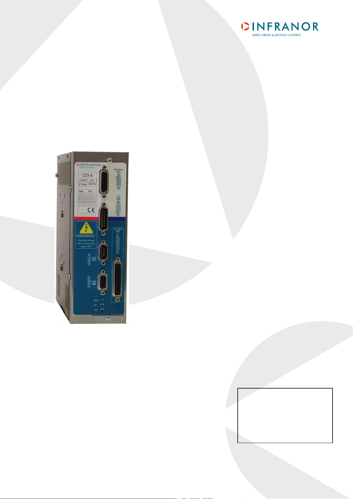
CD1-k
Installation Guide
CANopen
amplifier
INFRANOR®
CD1-k 1
CD1-k- Installation guide
WARNING
This is a general manual describing a series of servo amplifiers having output capability suitable for driving AC
brushless sinusoidal servo motors.
Please see CD1-k User Guide for the operation of the amplifier (commissioning, configuration, ...).
For the CANopen communication, see manual CD1-k – CANopen Communication Profile.
Instructions for storage, use after storage, commissioning as well as all technical details require the
MANDATORY reading of the manual before getting the amplifiers operational.
Maintenance procedures should be attempted only by highly skilled technicians having good knowledge
of electronics and servo systems with variable speed (EN 60204-1 standard) and using proper test
equipment.
The conformity with the standards and the "CE" approval is only valid if the items are installed according to the
recommendations of the amplifier manuals. Connections are the user's responsibility if recommendations and
drawings requirements are not met.
INFRANOR does not assume any responsibility for any physical or material damage due to improper handling or
wrong descriptions of the ordered items.
Any intervention on the items, which is not specified in the manual, will immediately cancel the warranty.
Infranor reserves the right to change any information contained in this manual without notice.
Any contact with electrical parts, even after power down, may involve physical damage.
Wait for at least 5 minutes after power down before handling the amplifiers (a residual voltage of several
hundreds of volts may remain during a few minutes).
ESD INFORMATION (ElectroStatic Discharge)
INFRANOR amplifiers are conceived to be best protected against electrostatic discharges. However,
some components are particularly sensitive and may be damaged if the amplifiers are not properly
stored and handled.
STORAGE
- The amplifiers must be stored in their original package.
- When taken out of their package, they must be stored positioned on one of their flat metal
surfaces and on a dissipating or electrostatically neutral support.
- Avoid any contact between the amplifier connectors and material with electrostatic potential
HANDLING
ELIMINATION
In order to comply with the 2002/96/EC directive of the European Parliament and of the Council of
27 January 2003 on waste electrical and electronic equipment (WEEE), all INFRANOR devices
have got a sticker
the 2002/96/EC Directive
This symbol indicates that INFRANOR devices must be eliminated by selective disposal and not
with standard waste.
(plastic film, polyester, carpet…).
- If no protection equipment is available (dissipating shoes or bracelets), the amplifiers must
be handled via their metal housing.
-
symbolizing a crossed-out wheel dustbin as shown in Appendix IV of
.
© INFRAN
!
O
August 2008. All rights reserved.
R,
Issue: 5.
7
2
CD1-k- Installation guide

CD1-k – Installation Guide
Content
PAGE
CONTENT ............................................................................................................................................... 3
CHAPTER 1 – GENERAL DESCRIPTION............................................................................................. 5
- INTRODUCTION............................................................................................................................. 5
1
- DESCRIPTION / COMPLIANCE WITH THE STANDARDS............................................................ 5
2
2.1 - GENERAL DESCRIPTION.......................................................................................................5
2.2 - REFERENCE TO THE STANDARDS: "CE" CERTIFICATION ............................................... 6
2.3 - REFERENCE TO THE STANDARDS: "UL" LISTING ............................................................. 6
3
- OTHER DOCUMENTS REQUIRED FOR THE COMMISSIONING................................................ 6
CHAPTER 2 – SPECIFICATIONS.......................................................................................................... 7
1
- MAIN TECHNICAL DATA................................................................................................................ 7
1.1 - CD1-k-230/I SINGLE-AXIS AMPLIFIER .................................................................................. 7
1.2 - CD1-K-400/I SINGLE-AXIS AMPLIFIER.................................................................................. 7
1.3 - COMMON SPECIFICATIONS TO THE CD1-k-230/I AND CD1-k-400/I AMPLIFIER TYPES. 8
2
- DIMENSIONS................................................................................................................................ 11
2.1 - CD1-k-230/I AMPLIFIER…..................................................................................................... 11
2.2 - CD1-k-400/1.8 TO 7.2 A AMPLIFIER..................................................................................... 11
2.3 - CD1-k-400/14 A AMPLIFIER.................................................................................................. 11
2.4 - CD1-k-400/30/45/70 AND 90 A AMPLIFIER.......................................................................... 11
2.5 - BRAKING RESISTOR dp 100/100, dp 200/100, dp 50/200, dp33/280 AND EF 400V.......... 12
3
- FASTENING.................................................................................................................................. 13
3.1 - CD1-k-230/I AMPLIFIER…..................................................................................................... 13
3.2 - CD1-k-400/1.8 TO 7.2 A AMPLIFIER..................................................................................... 13
3.3 - CD1-k-400/14 A AMPLIFIER….............................................................................................. 13
3.4 - CD1-k-400/30/45/70 AND 90 A AMPLIFIER.......................................................................... 13
4
- MULTIAXIS CABINET MOUNTING .............................................................................................. 14
4.1 - CD1-k-230/I AMPLIFIER…..................................................................................................... 14
4.2 - CD1-k-400/1.8 TO 7.2 A AMPLIFIER..................................................................................... 14
4.3 - CD1-k-400/14 A AMPLIFIER.................................................................................................. 14
4.4 - CD1-k-400/30/45/70 AND 90 A AMPLIFIER.......................................................................... 14
CHAPTER 3 – INPUTS-OUTPUTS ......................................................................................................15
1
- CONNECTORS LOCATION ......................................................................................................... 15
1.1 - SINGLE-AXIS AMPLIFIERS CD1-k-230-I AND CD1-k-400-I ................................................ 15
1.2 - CD1-k-400/30/45/70 AND 90 AMPLIFIER ............................................................................. 15
2
- LED DISPLAY ............................................................................................................................... 16
2.1 - IDENTIFICATION OF THE LEDs........................................................................................... 16
3
- AMPLIFIER ADDRESSING: SELECTION OF THE TRANSMISSION SPEED............................. 17
4
- X1 CONNECTOR: RESOLVER SENSOR ....................................................................................... 18
5
- X2 CONNECTOR: INPUTS-OUTPUTS ........................................................................................ 18
5.1 - SPECIFICATION OF THE LOGIC INPUTS: INHIBIT, FC+, FC-, INDEX, CAPTURE, LOW
SPEED............................................................................................................................................ 19
5.2 - SPECIFICATION OF THE LOGIC OUTPUT "AOK" ON RELAY........................................... 19
5.3 - SPECIFICATION OF THE LOGIC OUTPUTS ....................................................................... 19
5.4 - SPECIFICATION OF THE ANALOG INPUTS ....................................................................... 19
6
- X3 CONNECTORS: ENCODER.................................................................................................... 20
6.1 - X3 CONNECTOR FOR TTL INCREMENTAL ENCODER & HES INPUT (Sub D 25 pins
female)............................................................................................................................................ 20
6.2 - X3 CONNECTOR FOR SinCos INCREMENTAL ENCODER & HES INPUT (Sub D 25 pins
female)............................................................................................................................................ 21
6.3 – X3 CONNECTOR FOR ABSOLUTE SINGLE-TURN SinCos ENCODER (Sub D 25 pins
female)............................................................................................................................................ 22
6.4 - X3 CONNECTOR FOR "PULSE / DIRECTION" INPUTS (Sub D 25 pins female)................ 23
3
Content

CD1-k- Installation Guide
6.5 - X3 CONNECTOR FOR ENCODER OUTPUT (Sub D 25 pins female) ................................. 24
7
- X6 AND X7 CONNECTORS: CAN-OPEN ...................................................................................... 24
8
- X5 CONNECTOR: RS-232............................................................................................................ 24
9
- X8 CONNECTOR: AUXILIARY SUPPLY AND BRAKE ................................................................ 25
10
- X9 CONNECTOR: POWER........................................................................................................ 25
CHAPTER 4 - CONNECTIONS............................................................................................................ 26
- CONNECTION DIAGRAMS.......................................................................................................... 26
1
1.1 - CD1-k-230/I AMPLIFIER ........................................................................................................ 26
1.2 - CD1-k-400/I AMPLIFIER ........................................................................................................ 27
1.3 - CONNECTION OF THE SERIAL LINK .................................................................................. 28
1.4 - CONNECTION OF A BACKUP BATTERY ............................................................................ 28
1.5 - CONNECTION FOR A MULTIAXIS APPLICATION .............................................................. 28
2
- WIRING RECOMMENDATIONS................................................................................................... 29
2.1 - GROUND CONNECTIONS AND GROUNDING.................................................................... 29
2.2 - SHIELD CONNECTION OF THE CONNECTORS ................................................................ 30
2.3 - CONNECTION VUE OF CD1-K-400/30/45/70 AND 90......................................................... 31
2.4 - MOTOR, RESOLVER AND ENCODER CABLES ................................................................. 31
2.5 - SERIAL LINK AND CAN COMMUNICATION CABLES......................................................... 32
2.6 - CONNECTION CABLES OF THE BRAKING RESISTOR..................................................... 32
3
- FIRST POWERING OF THE AMPLIFIER ..................................................................................... 33
3.1 - VERY IMPORTANT................................................................................................................ 33
3.2 - SWITCHING ON THE 24 Vdc SUPPLY................................................................................. 33
3.3 - SWITCHING ON THE POWER SUPPLY (230 Vac or 400 Vac according to the
amplifier type) ................................................................................................................................. 33
3.4 - COMMISSIONING.................................................................................................................. 33
4
- REQUIREMENTS FOR THE COMPLIANCE WITH THE UL STANDARDS ................................. 33
4.1 - CONNECTION BY MEANS OF A FASTON SOCKET........................................................... 33
4.2 - 24 V SUPPLY ......................................................................................................................... 33
4.3 - POWER SUPPLY AND UL FUSE RATING ........................................................................... 34
4.4 - CD1-k-230/I AMPLIFIER: CONNECTION DIAGRAM WITH PROTECTIONS BY
"UL" FUSES.................................................................................................................................... 35
4.5 - CD1-k-400/I AMPLIFIER: CONNECTION DIAGRAM WITH PROTECTIONS BY
"UL" FUSES.................................................................................................................................... 36
4.6 - CONNECTION EXAMPLE FOR A UL COMPLIANT MULTIAXIS APPLICATION ............... 37
.................................................................................................................... 38
CHAPTER 5 - APPENDIX
1
- HARDWARE ADJUSTMENTS OF THE LOGIC BOARD.............................................................. 38
2
- ADJUSTMENT TO VARIOIUS RESOLVER TYPES..................................................................... 39
- USE OF THE "AOK" OUTPUT ...................................................................................................... 39
3
4
- ENERGY RECUPERATION VIA A BRAKING RESISTOR ................................................................. 40
- ORDER CODE .............................................................................................................................. 40
5
4
Content

CD1-k – Installation Guide
Chapter 1 – General description
1 - INTRODUCTION
CD1-k all-digital amplifiers with sinusoidal PWM control are servo amplifiers that provide the control of brushless
AC motors with a position sensor.
The CD1-k amplifier is a stand-alone single-axis block including power supply unit and mains filters. It is available
in both 230 VAC and 400/480 VAC mains operated voltages.
2 - DESCRIPTION / COMPLIANCE WITH THE STANDARDS
2.1 - GENERAL DESCRIPTION
The CD1-k amplifier directly controls the motor torque and speed by means of the information provided by a high
resolution position sensor (resolver or encoder). The sinusoidal current commutation based on this high resolution
position sensor provides very smooth motor torque/force control.
The CD1-k amplifier can be configured for the feedback of various position sensor types. The appropriate position
sensor configuration is selectable by software and saved in the amplifier.
- With a resolver sensor feedback, the motor absolute position value over one revolution is available and the
servo motor can immediately be enabled after the amplifier power up.
- With a "SinCos tracks" sensor which provides two analog Sin and Cos signals electrically compliant with the
SinCos encoder signals and which period is equal to the motor pole pitch, the servo-motor can be immediately
enabled after the powering of the drive.
- With an absolute single-turn SinCos encoder feedback (Heidenhain ERN 1085 or compliant), the servo
motor can also immediately be enabled after the amplifier power up.
- With an incremental encoder only, a motor phasing procedure (Phasing) must be executed at each amplifier
power up before the motor enabling.
- With an incremental encoder + Hall Effect Sensors (HES) feedback, the motor phasing procedure is no more
necessary and the servo motor can immediately be enabled after the amplifier power up.
- With an absolute single-turn, multi-turn or linear encoder using the ENDAT or HIPERFACE communication
protocols and fitted with incremental SinCos outputs, the servo-motor can also be immediately enabled after the
powering of the drive.
Series CD1-k amplifiers have their own DC/DC converter to provide appropriate logic voltage to the modules. An
auxiliary 24VDC +/- 15 % supply is generally available on all machines and supplies a DC/DC converter with all
logic supplies required by the amplifier. The auxiliary supply allows to keep the logic board on, after the power
supply has been switched off, in order to keep the position output and to avoid initializing the machine all over
again. A 24 VDC battery supply with specific wiring allows to keep the position even after switching off the
auxiliary 24 VDC supply. This wiring can be used for "absolute" operation with the CD1-k amplifier (see chapter 4:
Connections).
The power supply is depending on the amplifier type:
• CD1-k-230/I: 230 VAC single-phase mains operation power supply or three-phase via a transformer or
an auto-transformer or three-phase mains operation if there are three-phase mains available in 200 to
230 VAC.
• CD1-k-400/I: 400 to 480 VAC three-phase mains operated power supply.
A soft start system of the power supply allows to limit the inrush current at power on.
The very small dimensions of the CD1-k amplifier allow an optimum integration in 300 mm deep cabinets
(connectors included).
Chapter 1 - General description
5

CD1-K- Installation Guide
2.2 - REFERENCE TO THE STANDARDS: "CE" CERTIFICATION
Series CD1-k amplifiers have been approved with regard to their conformity with the Electromagnetic Compatibility
standards concerning the power servos referenced in the EN 61800-3:2004 standard "Electrical variable speed
power servo systems":
- EN 55011, group 1, C3 category, regarding radiated radioelectric disturbances,
- EN 61000.4-2-3-4-5 regarding immunity.
Standard to be applied to the electrical equipment of industrial machines: EN 60204-1.
These items have been "CE" marked since year 2000.
2.3 - REFERENCE TO THE STANDARDS: "UL" LISTING
CD1-k series have been «
This product was evaluated to:
- the Third Edition of UL508C, the UL Standard for Power Conversion Equipment, dated May 2002 for the UL
Listing (USL),
- the CSA Standard for Industrial Control Equipment, C22.2 N° 14-95, dated August 1995 for the Canadian UL
Listing (CNL) except for CD1-k-400/70 and 90 drives.
Providing that the manual is specifying that the end user has to provide an isolated power supply, for 24 VDC
auxiliary input protected by a 4 A UL Listed fuse, the power board is considered within a limited voltage/current
circuit per section 31.4 of UL508C. Therefore, spaces on the power board are not required to be evaluated per
section 31.2 of UL508C and were evaluated according to UL 840.
Per UL 840 (Second Edition, dated May 20, 1993) requirements, spaces are limited to 2.5 mm assuming pollution
degree 2 environment.
Ground connection is fixed in the frame of the device by a rivet, Avibulb masse, BN10-5168. The connector
complies with standard dimensions given in table 6.2 of UL 310, the standard for Electrical Quick connect
terminals.
» listed according to UL508C and UL840 regarding the insulator.
cULus
3 - OTHER DOCUMENTS REQUIRED FOR THE COMMISSIONING
CD1-k User Guide,
CANopen communication protocol for CD1-k amplifiers.
"CD1-a/CD1-k SinCos track feedback" application note regarding the use of motors equipped with
"SinCos tracks" position sensors.
"CD1-a/CD1-k absolute encoders feedback" application note regarding the use of absolute single-turn,
multi-turn or linear encoders using the ENDAT or HIPERFACE Communication protocols.
6
Chapter 1 - General description

CD1-k – Installation Guide
Chapter 2 – Specifications
1 - MAIN TECHNICAL DATA
1.1 – CD1-k-230/I SINGLE-AXIS AMPLIFIER
Mains operated power supply voltage 230 Vac +10 % / -15 % single-phase or 3-phase
50 to 60 Hz
Isolated auxiliary logic and motor brake supply voltage 24 Vdc +/-15 % - 320 mA without brake
Motor phase-phase output voltage 200 Vrms
Integrated braking system External resistor 100 Ohm / 100 W (dp 100/100)
Minimum resistance: 50 Ohm
Minimum inductance between phases 1 mH
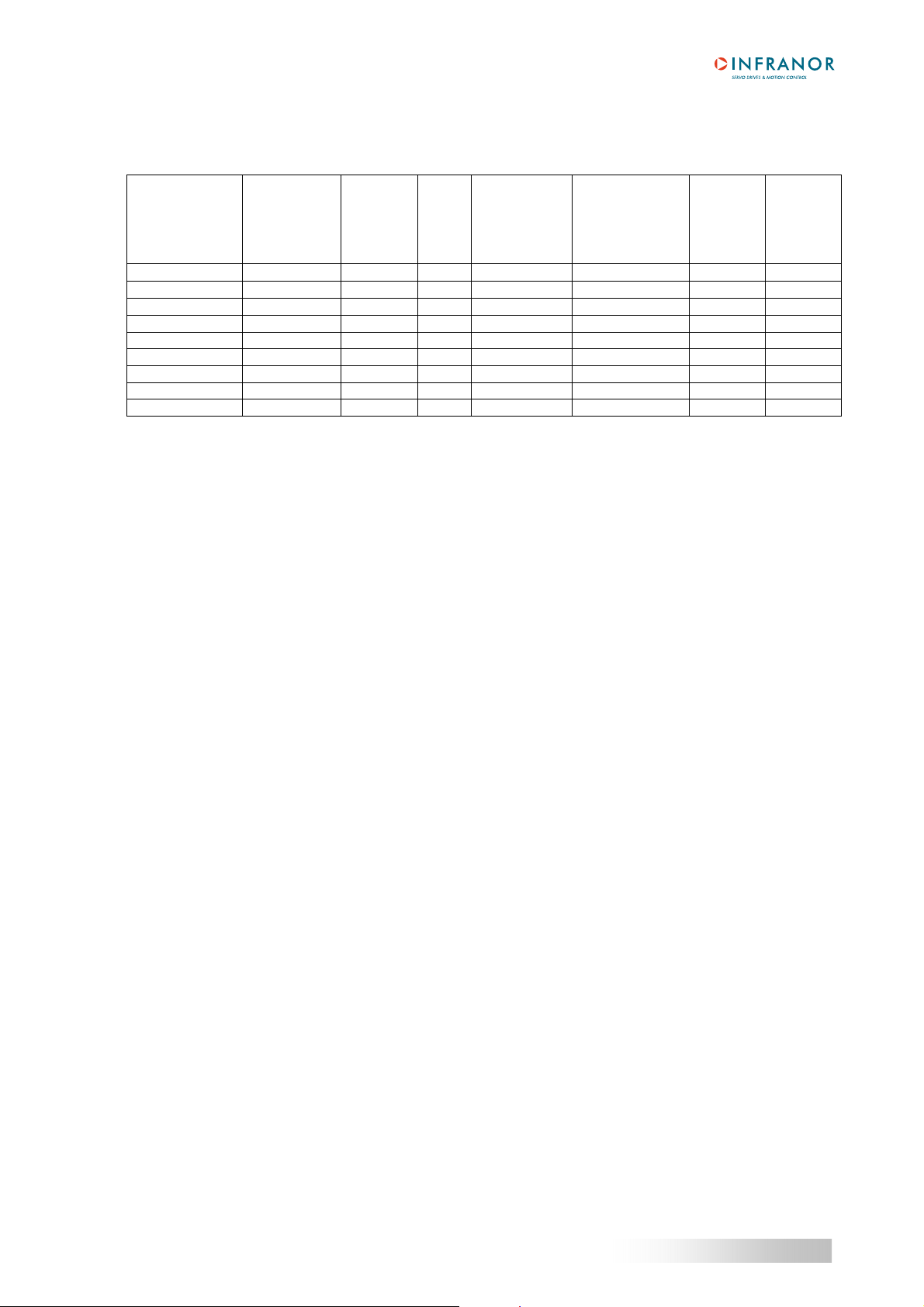
OUTPUT CURRENT RATINGS (at a maximum room temperature of 40°C)
Amplifier type
CD1-k-230/2.25 2.25 1.1 25 1.1 6 A 5 kA yes
CD1-k-230/4.5 4.5 2.25 30 2.25 6 A 5 kA yes
CD1-k-230/7.5 7.5 3.75 44 3.75 6 A 5 kA yes
CD1-k-230/10.5 10.5 5.25 55 5.25 6 A 5 kA yes
CD1-k-230/16.5 16.5 8.25 66 8.25 9 A 5 kA yes
1.2 - CD1-K-400/I SINGLE-AXIS AMPLIFIER
Mains operated power supply voltage 400 to 480 Vac +10 % / -15 % 3-phase, TN or TT
50 to 60 Hz (phase-earth voltage must be
Auxiliary logic and motor brake supply voltage 24 Vdc +/-15 % - 320 mA without brake
Motor phase-phase output voltage 380 to 460 Vrms depending on the mains
Integrated braking system CD1-k-400/1.8 to 7.2 A:
External resistor: 200 Ohm / 100 W (dp 200/100)
Minimum resistor value: 150 Ω/100 W
CD1-k-400/14 A:
External resistor: 50 Ohm / 200 W (dp 50/200)
CD1-k-400/30 and 45 A:
External resistor : 33 Ω/280 W (dp 33/280)
CD1-k-400/70 and 90 A:
External resistor: 16.5 Ω/560 W (EF 400V)
Minimum inductance between phases 2 mH
Max. output
current (Arms)
for 1 sec.
+/- 5 %
(230 VAC)
Rated
output
current
(Arms)
(230 VAC)
Power
losses
(W)
Rated input
current (Arms)
(230 VAC,
60 Hz)
Max. protection
fuses for line
circuit
RK5 listed
(Bussman /
Littelfuse)
system with earthed neutral point
balanced)
Shortcircuit
power of
the mains
UL listed
Chapter 2 - Specifications
7
CD1-K- Installation Guide
OUTPUT CURRENT RATINGS (at a maximum room temperature of 40°C)
Output voltage range for 400-480 VAC (rms) three-phase mains
Output current range: 1.8 A, 2.7 A, 5.1 A, 7.2 A, 14 A, 30 A, 45 A, 70 A, 90 A (rms)
Amplifier type
Max. output
current (Arms)
for 1 sec.
+/- 5 % (480
VAC)
Rated
output
current
(Arms)
(480 VAC)
Power
losses
(W)
Rated input
current (Arms)
(480 VAC,
60 Hz)
Max. protection
fuses for line
circuit
RK5 or A60Q40
for 400/70 and 90
listed
Shortcircuit
power of
the mains
UL listed
CD1-k-400/1.8 1.8 0.9 35 0.9 2 A 5 kA yes
CD1-k-400/2.7 2.7 1.35 43 1.35 2 A 5 kA yes
CD1-k-400/5.1 5.1 2.55 71 2.55 4 A 5 kA yes
CD1-k-400/7.2 7.2 3.6 93 3.6 4 A 5 kA yes
CD1-k-400/14 14 7 200 7 8 A 5 kA yes
CD1-k-400/30 30 15 400 15 20 A 5 kA yes
CD1-k-400/45 45 20 560 20 20 A 5 kA yes
CD1-k-400/70 70 35 650 35 40 A 5 kA
CD1-k-400/90 90 35 650 35 40 A 5 kA
In progress
In progress
1.3 – COMMON SPECIFICATIONS TO THE CD1-k-230/I AND CD1-k-400/I AMPLIFIER TYPES
Servo loops: current, speed and position Digital
Mains filter on power supply Integrated in the amplifier
Common mode filter on auxiliary supply Integrated in the amplifier
Common mode filter on motor brake supply Integrated in the amplifier
Position sensor Transmitter resolver
Absolute single-turn encoder (ERN1085 or compliant)
Incremental encoder (TTL or SinCos signals)
Incremental encoder + Hall Effect Sensors
Power stage protections See table of the main protections in the CD1-k User Guide
Motor brake control 1.5 A maximum with 24 Vdc.
PWM switching frequency 8 kHz
Minimum inductance between phases 1 mH pour 230 V / 2 mH pour 400 V
Digital current regulator (PI) Adjustable
Current loop bandwidth Cut-off frequency for 45° phase shift: 1000 Hz
Internal current limitation Imax: 20 % to 100 % and I rated: 20 % to 50 %
Authorized Imax duration = 1 second
Digital speed and position regulators Sampling period = 0.5 ms
Anti-wind-up system of the integrator
Adjustable digital gains
Speed loop bandwidth Selectable cut-off frequency for 45° phase shift:
50 Hz, 75 Hz or 100 Hz
Max. motor speed Adjustable from 100 rpm to 25 000 rpm
Resolver input Resolution : 65536 ppr (16 bit)
Excitation frequency: 8 kHz
Transformation ratio: 0.3 to 0.5 (other values need factory
adjustment)
8
Chapter 2 – Specifications

CD1-k – Installation Guide
Encoder input Software selectable:
Quadrature signals A & B with Z marker pulse
RS 422 line receiver
Maximum pulse frequency: 1 MHz
Resolution: 500 to 10
6
ppr
Incremental Sin/Cos encoder
Heidenhain 1Vcc Sin/Cos type or compliant
Maximum signal frequency: 200 kHz
Resolution: 500 to 10
6
ppr
Interpolation factor : 1024
Absolute single-turn Sin/Cos encoder
Heidenhain ERN 1085 or compliant
Maximum signal frequency: 200 kHz
Resolution: 2048 or 512 ppr
Interpolation factor : 1024
Pulse & Direction input Re-configuration of the encoder input for stepper motor
emulation:
Line receiver RS-422
Maximum pulse frequency: 1 MHz
Resolution: 200 to 10
6
pitch/revolution
Hall sensors input Software selectable: 120° or 60° HES type
5 V or 12 V supply voltage
HES sequence error detection
Logic inputs INHIBIT
FC+ and FC- limit switches
INDEX
CAPTURE
LOW SPEED
Logic outputs 4 logic outputs activated by bus
Relay outputs Relay contact: open if error
Umax = 50 V, Imax = 100 mA, Pmax = 10 W
Open collector output protected against load
Motor brake coil with 24 VDC/1.5 A
short-circuit
Analog inputs Re-configuration of the logic outputs by means of jumpers:
+/- 10 V, resolution = 14 bits
Encoder position output Re-configuration of the TTL encoder input via CANopen:
Two A and B channels in quadrature + 1 marker pulse per
revolution
RS 422 line driver
Programmable resolution: 64 ppr to 16384 ppr (according to
the maximum motor speed)
Arc minute accuracy = (8 + 5400/Resolution)
Note
: The total position accuracy must take into account the
accuracy of the resolver used.
CAN interface CANopen protocol (DS 301 – DSP 402)
Error display LEDs on front panel + diagnostic via serial link RS 232 +
diagnostic via CANopen.
Motor and application parameter setting Serial link RS 232 or
bus interface with CANopen protocol
Automatic functions Amplifier adjustment to the motor (AUTO-PHASING)
Servo control adjustment (AUTO-TUNING)
Chapter 2 - Specifications
9

CD1-K- Installation Guide
Compliance with the standards: CE certification.
360° shield connection, equipotentiality according
to the wiring rules.
CD1-400/70 and 90 A with mains filtre F-40070/90.
Conformity with the standards:
UL listing
"360°" shield; equipotentiality according to the
wiring rules.
EMC standards:
- immunity: EN 61000.4-2-3-4-5
- conducted and radiated disturbances: EN 55011, Group 1,
C3 category
Electrical standards for industrial machines:
- EN 60204-1: insulator 1500 Vac / 1 mn
leakage current > 30 mA (EMI filters).
CD1-k series have been “
” listed according to UL508C
cULus
and UL840 regarding the insulator.
This product was evaluated to:
- the Third Edition of UL508C, the UL Standard for Power
Conversion Equipment, dated May 2002 for the UL Listing
(USL),
- the CSA Standard for Industrial Control Equipment, C22.2
N° 14-95, dated August 1995 for the Canadian UL Listing
(CNL) except for CD1-k-400/70 and 90 drives.
Temperature
- storage: -20° C to +70° C
- operation: +5° C to +40° C
From 40° C, the rated currents must be reduced of
3 % per additional Celsius degree
Max. temperature: 50° C
Altitude 1000 m
Moisture < 50% at 40° C and < 90% at 20° C: EN 60204-1 standard
Condensation prohibited (storage and operation)
Cooling Forced air (fan integrated in the CD1-k amplifier)
Check for free ventilation and no upper or lower obstruction of
the air admissions
Mounting position Vertical
Environment Open chassis to be mounted in a housing protecting the
amplifier from conducting dust and condensation (pollution
degree 2 environment)
Mounting location Closed cabinet without any conducting and/or corroding
agents and according to the environment conditions
requirements
Condensation prohibited
Weight CD1-k-230/I: about 1 kg
CD1-k-400/1.8 to 7.2 A: about 1.5 kg
CD1-k-400/14: about 3 kg
CD1-k-400/30 and 45: about 4.8 kg
CD1-k-400/70 and 90: about 5.3 kg
10
Chapter 2 – Specifications
CD1-k – Installation Guide
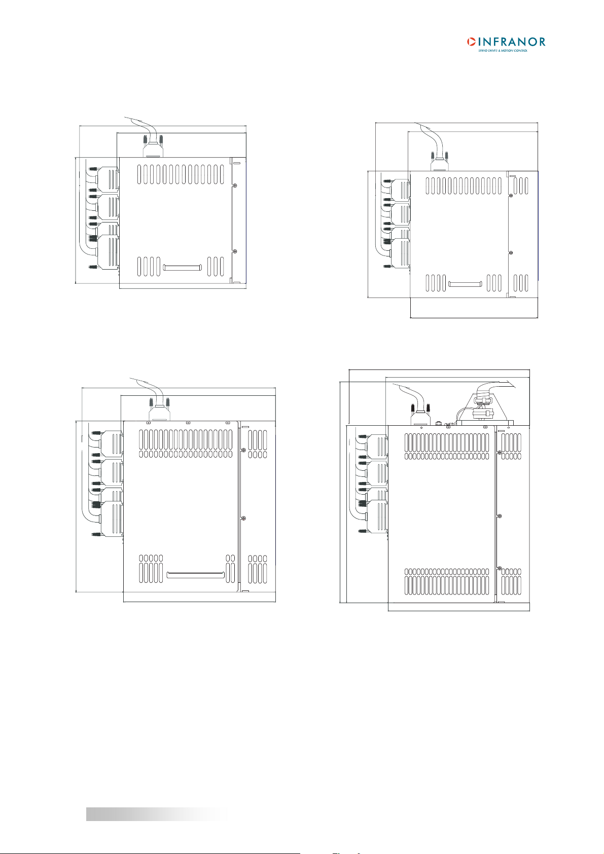
2 - DIMENSIONS
2.1 - CD1-k-230/I AMPLIFIER 2.2 - CD1-k-400/1.8 TO 7.2 A AMPLIFIER
260
203
293
234
200
228
199
230
2.3 - CD1-k-400/14 A AMPLIFIER 2.4 - CD1-k-400/30/45/70 AND 90 A AMPLIFIER
293
234
293
234
258
UV
W
381
288
230
230
Chapter 2 - Specifications
11

CD1-K- Installation Guide
2.5 - BRAKING RESISTOR dp 100/100, dp 200/100, dp 50/200, dp33/280 AND EF 400V
A
B
7
7
83
40
C
DIMENSIONS dp 50/200, dp 100/100 and dp 200/100 dp 33/280, EF 400V
A 157 mm 290 mm
B 145 mm 278 mm
C 52 mm 57 mm
12
Chapter 2 – Specifications
 Loading...