

Page 1

InfoPrint 6500 Line Matrix Printers
User’s Manual for DBCS Models
Cabinet and Pedestal
S550-1008-02
Page 2

Page 3

InfoPrint 6500 Line Matrix Printers
User’s Manual for DBCS Models
Cabinet and Pedestal
S550-1008-02
Page 4

Third Edition (May 2011)
Before using this information and the product it supports, read the information in “Notices” on
page 199.
Note!
Visit our home page at: http://www.infoprint.com
Internet
This edition applies to the InfoPrint 6500 Line Matrix Printer and replaces the following publication:
InfoPrint 6500 Line Matrix Printers: User’s Manual, S550-1008-01.
You can send comments by e-mail to [email protected] or by mail to:
InfoPrint Solutions Company, LLC
6300 Diagonal Hwy 002J
Boulder, CO 80301-9270
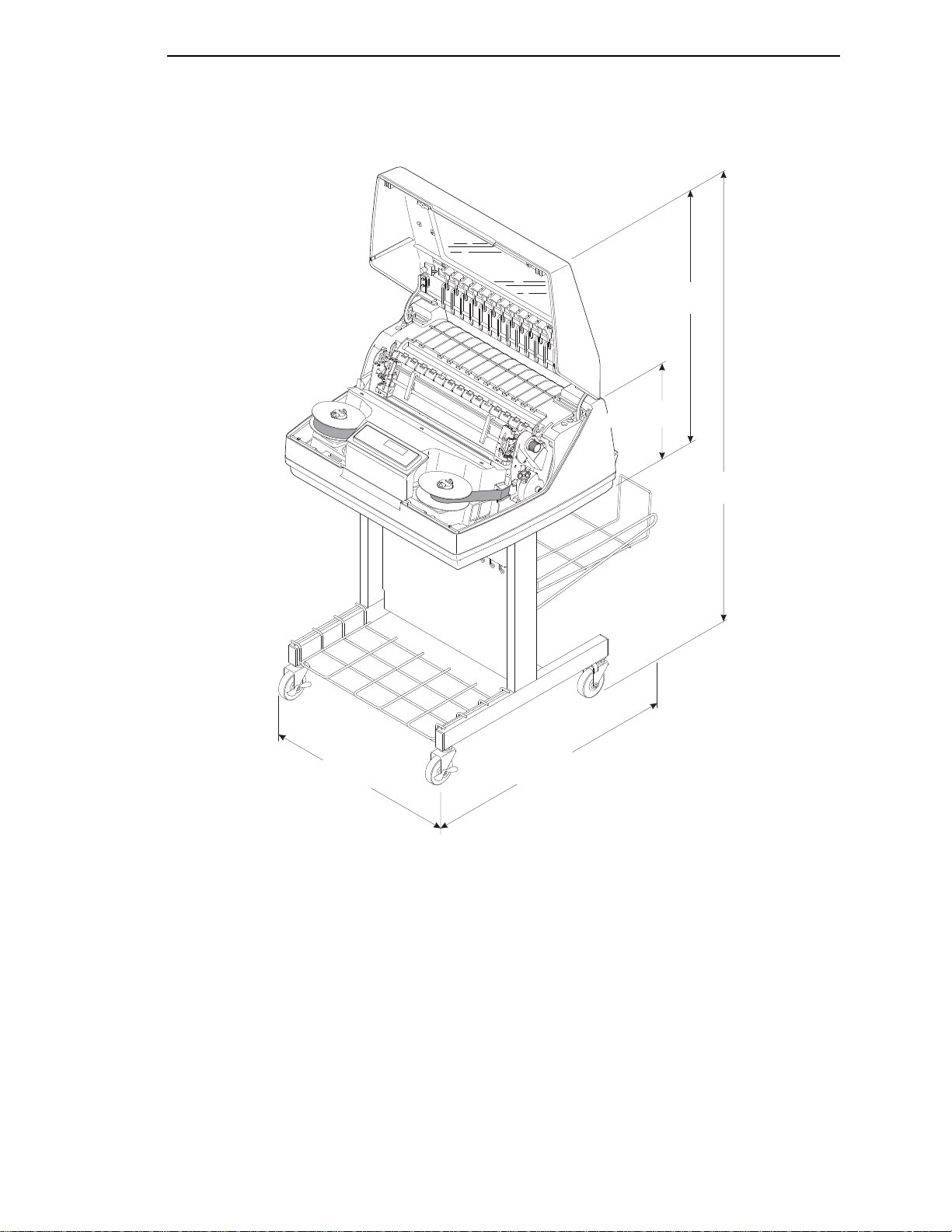
U.S.A.
This product is or contains commercial computer software and commercial computer software
documentation developed exclusively at private expense. As specified in Federal Acquisition
Regulation 12.212 in the case of civilian agencies and Defense Federal Acquisition Regulation
Supplement 227.7202 in the case of military agencies, use, duplication and disclosure by agencies
of the U.S. Government shall solely be in accordance with the accompanying International
Program License Agreement in case of software products and in accordance with the licensing
terms specified in the product’s documentation in the case of hardware products.
© Copyright InfoPrint Solutions Company 2008, 2011. All rights reserved.
Page 5
Safety Noti ces
DANGER:
This product is equipped with a 3-wire power cord and plug for the user’s safety. Use this power
cord in conjunction with a properly grounded electrical outlet to avoid electrical shock.
CAUTION:
<1> Before powering on the printer ensure the printer is plugged
into an appropriate power source. Refer to Chapter 2 of the
User’s Manual for information on the proper source.
<2> Switch off the printer power and unplug the printer power
cord before cleaning the printer.
<4> Do not connect or disconnect any communication port,
teleport, attachment connector, or power cord during an
electrical storm.
<5> Power off the printer and disconnect the power cord before
connecting or disconnecting any communication port,
teleport, or attachment cable connector.
Page 6

Page 7

Table of Contents
1 Introduction ......................................................... 11
About This User’s Manual.................................................................... 11
Notes And Notices ........................................................................ 11
Conventions In This User’s Manual............................................... 12
Related Documents....................................................................... 12
Printer Overview .................................................................................. 13
The InfoPrint 6500-D Printer Family.............................................. 13
How To Identify The Printer........................................................... 14
RibbonMinder ................................................................................ 14
Standard Capabilities .................................................................... 16
Optional Features.......................................................................... 18
Protocols And Emulations ............................................................. 18
Taking Care Of Your Printer.......................................................... 19
2 Installation........................................................... 21
Installation, Attachment, And Configuration Overview......................... 21
Before You Begin................................................................................. 22
Power Requirements ........................................................................... 23
Select A Site ........................................................................................ 23
Printer Dimensions .............................................................................. 24
Printer Component Locations .............................................................. 26
3 Configuring the Printer ........................................ 29
Overview.............................................................................................. 29
The Configurations ........................................................................ 29
Active Versus Saved Configurations ............................................. 30
The Configuration Main Menu ............................................................. 30
Using The Operator Panel ................................................................... 33
Program Mode ..................................................................................... 38
Unlocking The Program Mode....................................................... 38
Locking The Program Mode .......................................................... 38
Entering Program Mode ................................................................ 38
Printing The Current Configuration ...................................................... 39
Changing Parameters.......................................................................... 41
Saving Your Configuration In A Custom Set........................................ 43
Page 8

Table of Contents
Loading Custom Sets Or Factory Default Values ................................ 46
Changing The Power On Configuration............................................... 48
4 The Configuration Menus.................................... 51
Configuration Overview ....................................................................... 51
Main Menu ........................................................................................... 52
Quick Setup Menu ............................................................................... 54
Printer Control Menu............................................................................ 57
Configuration Management Menu ....................................................... 65
Ethernet Address Menu ....................................................................... 69
Ethernet Parameters Menu.................................................................. 70
Adapter Address Menu ........................................................................ 73
Adapter Parameters Menu................................................................... 74
Wireless Address Menu....................................................................... 77
Wireless Parameters Menu ................................................................. 79
Parallel Interface Menu........................................................................ 84
PC Parallel Menu .......................................................................... 86
IEEE 1284 Menu ........................................................................... 89
Serial Interface Menu........................................................................... 91
Emulation Configuration Menu ............................................................ 97
Printer Emul Config Menu ............................................................. 98
Print Format Menu ........................................................................ 99
Operator Print Tests Menu ................................................................ 110
Printer Information Menu ................................................................... 112
5 Printer Interfaces............................................... 115
Overview............................................................................................ 115
RS-232 And RS-422 Serial Interfaces ............................................... 116
RS-232 ........................................................................................ 116
RS-422 ........................................................................................ 117
RS-232 Serial Interface Protocols............................................... 117
RS-232 And RS-422 Serial Interface Protocols .......................... 118
RS-232 And RS-422 Serial Interface Error Handling .................. 118
RS-232 And RS-422 Serial Interface Configuration .................... 119
PC Parallel Interface.......................................................................... 120
PC Parallel Interface Signals ...................................................... 121
PC Parallel Interface Configuration ............................................. 121
IEEE 1284 Parallel Interface.............................................................. 122
Operating Modes......................................................................... 122
The Negotiation Phase................................................................ 123
Signals ........................................................................................ 123
Terminating Resistor Configurations........................................... 126
Page 9

Table of Contents
6 Routine Service and Diagnostics...................... 129
Cleaning Requirements ..................................................................... 129
Exterior Cleaning......................................................................... 129
Interior Cleaning .......................................................................... 129
Printer Self –Tests ............................................................................. 132
Running The Printer Self–Tests......................................................... 133
Hex Code Printout ............................................................................. 134
Fault Messages ................................................................................. 137
Fault Correction Procedure ......................................................... 137
A Printer Specifications ........................................ 175
Ribbon Specifications ........................................................................ 175
Ordering Ribbons............................................................................... 175
Paper Specifications .......................................................................... 178
Paper........................................................................................... 178
Labels.......................................................................................... 178
Printer Dimensions and Weight ......................................................... 179
Cabinet Models ........................................................................... 179
Pedestal Models.......................................................................... 179
Environmental Characteristics........................................................... 180
Temperature................................................................................ 180
Relative Humidity ........................................................................ 180
Acoustic Noise Level ................................................................... 180
Electrical Characteristics ................................................................... 181
Input Voltage ............................................................................... 181
Power Consumption .................................................................... 181
Interfaces ........................................................................................... 181
Cables................................................................................................ 182
Printing Rates .................................................................................... 182
B A Quick Look at Line Matrix Printing................. 185
Character Formation.......................................................................... 185
Printing Speed ................................................................................... 187
Glossary............................................................ 189
Notices .............................................................. 199
Product Recycling And Disposal........................................................ 202
Trademarks........................................................................................ 202
Communication Statements............................................................... 203
Limited Software Product Warranty............................................. 210
Page 10

Table of Contents
Page 11
1
DANGER
CAUTION
CAUTION
Introduction
About This User’s Manual
This User’s Manual is designed so that you can quickly install and configure
your InfoPrint 6500-D printer.
Notes And Notices
For your safety and to protect valuable equipment, it is very important that you
read and comply with all information noted in the following section:
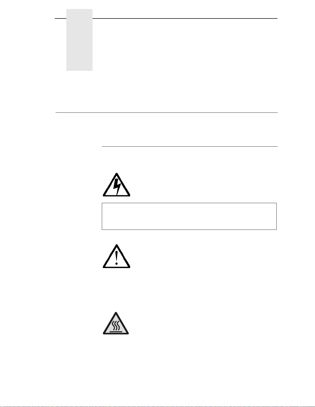
<#> The word Danger next to the lightning slash indicates the presence of a
hazard that could cause death or serious personal injury. Danger and
Caution notices are numbered to help you find the translated versions
in the InfoPrint 6500 Safety Notices booklet.
<#> The word Caution next to the exclamation point (!) indicates the
presence of a hazard that could cause moderate or minor personal
injury.
<#> The word Caution next to this symbol indicates a part or assembly that
is hot enough to burn you.
11
Page 12

Chapter 1
About This User’s Manual
ATTENTION
The word Attention indicates the possibility of damage to a program,
device, system, or data.
IMPORTANT
The word Important indicates information vital to proper operation of
the printer.
NOTE: A note gives you helpful information and tips about printer operation
and maintenance.
Conventions In This Use r’s Manua l
Operator panel keys and LCD messages are set off from regular text in this
manual:
•
Operator panel keys and indicators are printed boldface and
UPPERCASE.
Example: Press the CANCEL key, then press the START key.
•
Liquid Crystal Dislay (LCD) messages are printed in capital letters inside
quotation marks ( “ ” ).
Example: Press the STOP key. “NOT READY” appears on the LCD.
•
Key combinations are denoted by the + (plus) symbol.
Example: Press SCROLL/MICRO + SCROLL/MICRO means press
the SCROLL/MICRO key and the SCROLL/MICRO key at the same
time.
Related Documents
•
InfoPrint 6500 Line Matrix Printers: LQ-1600K Programmer’s Reference
Manual — Provides description of LQ-1600K printer codes and character
sets.
•
IInfoPrint 6500 Line Matrix Printers: KS/KSSM Programmer’s Reference
Manual — Provides description of KS and KSSM printer codes and
character sets.
•
InfoPrint 6500 Line Matrix Printers: Ethernet Interface User's Manual —
Information about network protocols, configuration, and operation.
•
InfoPrint 6500 Line Matrix Printers: Quick Setup Guide — Explains how to
unpack and set up the printer.
12
Page 13

Printer Overview
This chapter provides a general overview of your printer and the conventions
used within this manual.
The InfoPrint 6500-D Printer Family
The InfoPrint 6500-D series consist of 300, 600, and 800 lines per minute
(lpm) models and are packaged in various configurations. All of the models
offer software versatility and the latest refinements in line matrix printing
technology. The print mechanisms are housed in sound-insulated cabinets
which make the printer family among the quietest printers in the world.
Additionally, your printer has a flexible architecture that allows you to add new
features and emulations as they become available.
LQ-1600K, KS, or KSSM will be the standard emulation. No matter what
emulation is installed, your printer is easy to use. The message display and
lights on the control panel communicate with you directly and clearly. You can
select every function on your printer at the control panel, or you can send
commands from the host computer.
The InfoPrint 6500-D Printer Family
The printer combines the use of Flash, RAM, and nonvolatile RAM for
program execution. The Flash is used for all program, font, and emulation
storage. New fonts, emulations, or program updates can be downloaded to
Flash memory via the parallel or serial interface, or through the Ethernet
interface. The RAM is used for buffers, print image storage, and execution
variables. The non-volatile RAM stores configuration, statistics, and internal
parameters.
T a ble 1. The InfoPrint 6500-D Printer Family
Model Number Print Speed Enclosure Hammer Bank
6500-D3C 300 LPM Floor Cabinet 60 Hammers
6500-D3P 300 LPM Pedestal 60 Hammers
6500-D6C 600 LPM Floor Cabinet 102 Hammers
6500-D8C 800 LPM Floor Cabinet 126 Hammers
13
Page 14

Chapter 1
InfoPrint 6500-D Printer Family
6500-D3P
Letter Code:
P = Pedestal Model
C = Cabinet Model
Speed Rating:
D3C = 300 LPM
D3P = 300 LPM
D6C = 600 LPM
D8C = 800 LPM
Printer Overview
How To I de nti fy T he Prin ter
The model number of the printer indicates the printer family, rated maximum
print speed, and type of enclosure. (See
Figure 1.)
RibbonMinder
The 6500-D has a new feature that automatically monitors and communicates
ribbon life. Using a specially barcoded spool, the printer can automatically
detect when a new or used ribbon is loaded, and all ribbon properties. With a
sophisticated algorithm, the system monitors all jobs printed and
automatically updates the remaining ribbon life on the front panel display. This
allows the system administrator to have precise control over print quality and
consumable costs. The accurate presentation of available ribbon life allows
for efficient planning of print jobs. For example, you can install a new ribbon
before printing large print jobs.
When the ribbon life gets near the end point, the printer displays a ribbon low
message and flashes the indicator light. Printing will continue without
interruption. Once the ribbon reaches 0% remaining, the alarm sounds, the
indicator light flashes, the display updates, and printing pauses. If a new
ribbon is loaded, the system automatically detects the change, clears the
condition, and restarts the life at 100%. If it is not convenient to change the
ribbon immediately, cycle the printer on and offline and it will resume printing
for a few minutes. This should be enough to complete the job. If not, repeat
the same procedure indefinitely to extend printing on the same ribbon.
Figure 1. Printer Model Number Interpretation
14
Page 15

RibbonMinder
Output Darkness
By default the system is configured to meet most user requirements.
However, some applications require that the output remains darker than the
nominal set point while some applications are less critical and could tolerate a
lighter final image. The system can easily adjust to this variability. A setting
under Printer Control, Ribbon End Point is available that allows the user to
adjust the final output. The range is as follows:
Lighter -7 (Default)
Darker +1 through +6
Normal
Lighter -1 through -10
The ribbon life indicator always cycles between 100% and 0%, but if a darker
setting is selected, zero will be reached more quickly. If a lighter setting is
selected, the system will extend the amount of printing it takes to reach zero.
Ribbon Flipping
In some cases, the application’s print pattern is narrow enough where only
half of the ribbon is used when printing. In these cases, you can flip the ribbon
and use the other half. The RibbonMinder detects the flip and resets the
ribbon life to 100%.
NOTE: It is the user’s responsibility to ensure the print pattern is sufficiently
narrow to support flipping. If not, the ribbon life may falsely indicate
100% for the flipped ribbon.
Loading a Used Ribbon
You can take ribbons off the printer and reload it at a later time. The ribbon life
gauge automatically updates to reflect the correct remaining capacity.
NOTE: The ribbon must be reloaded back onto the same printer, and in the
same orientation as it was removed. If the used ribbon is loaded onto
a different printer, or if it is flipped over, it will incorrectly indicate the
ribbon as new.
Ribbon Log
The RibbonMinder tracks all used ribbons. This data allows you to monitor
how many ribbons and ribbon types have been used on the printer. This data
is contained in the ribbon log. To print the ribbon log, see page
110.
15
Page 16

Chapter 1
Printer Overview
Consumable Monito ring With T he Pr inter M an agemen t U tility
The RibbonMinder works with the Printer Management Utility (PMU).
The PMU allows a system administrator to remotely view the current
consumable status of all printers. The PMU can be configured to deliver alerts
on all consumable warnings. When a ribbon reaches the low state, the PMU
notifies the system administrator remotely via an automated e-mail alert of the
low condition. This allows corrective action to be taken before the ribbon
reaches its end of life. If the ribbon is not changed, an alert will again be
initiated once the ribbon reaches the 0% end point. Refer to your Printer
Management Utility User’s Manual for details.
St andard Capab ilities
The 6500-D printer family has the following general characteristics:
•
A broad range of print speeds in both cabinet and pedestal models
•
Support of similar features across the entire product line to allow
maximum flexibility in matching the printer to the requirements
•
Energy Star compliant
The following sections summarize the standard capabilities of the InfoPrint
6500-D printers.
Host Computer Interfaces
•
RS 232 Serial
•
RS 422 Serial
•
PC Parallel
•
Ethernet Interface
•
IEEE 1284
Printer Emulations
Each emulation provides a different set of configuration menus, control codes,
and character sets. The LQ-1600K printer emulation is standard for the
InfoPrint Hanzi GB and Big5 printer. The KS or KSSM printer emulation is
standard for the InfoPrint Hangul printer.
LQ-1600K Emulati on
The LQ-1600K emulation is used for the printing of Hanzi characters. The
emulation supports the GB18030-2000 CAT-A character set in InfoPrint Hanzi
GB printer.
16
KS And KSSM Emulation
The KS and KSSM emulation is used for the printing of Hangul characters and
supports the KSC5601 character set.
Page 17

Output Control
The printers have the following output control features:
•
LQ
•
Near LQ
•
Normal
•
Hi-Speed
•
Super Hi-Speed
•
Ultra Hi-Speed
•
Selectable pitch: normal, expanded and compressed
•
Emphasized (shadow) printing
•
Automatic unerlining and overscoring
•
Superscript and subscript printing
•
Double high and wide printing
Standard Capabilities
•
Resident multinational character sets
Graphics And V ertical Form atting
Several graphics and vertical formatting features are available:
•
Built-in graphics generators providing a variety of graphic density for
printing
•
Epson LQ dot graphics mode
•
Programmable electronic vertical formatting provides rapid vertical paper
movement to specified lines for printing repetitive and continuous forms.
Built-in Diagnostic Tools
The following diagnostic tools are provided with the printer:
•
Comprehensive diagnostic self-tests permanently stored in the printer
•
Configuration printout
•
Data stream hex code printout
17
Page 18

Chapter 1
Printer Overview
Optional Features
The following features can be ordered and installed on this printer. If you
ordered a feature at the time of purchase, the feature may already be installed
on your printer. Refer to the documentation shipped with the feature for more
details.
For detailed information about these features or for information on ordering a
feature, contact your InfoPrint sales representative.
•
Network Print Server:
Enables you to attach your printer to Local Area Networks using tokenring or Ethernet protocols. The Network Print Server functions as a
workstation server on your network, enabling your users to submit print
jobs to your printer.
The Network Print Server provides multiple network protocol support that
allows you to submit print jobs from Novell** Netware**, LAN Server,
AIX*, and other TCP/IP networks.
•
Ethernet Interface:
Enables you to attach your printer to Local Area Networks using Ethernet
protocols. The Ethernet Interface functions as a workstation server on
your network, enabling your users to submit print jobs to your printer.
•
Wireless:
An embedded wireless Ethernet Interface card that allows you to attach
printers on a local area network (LAN) rather than attaching them directly
to a host system.
Protocols And Emulations
A protocol is a set of rules governing the exchange of information between the
printer and its host computer. These rules consist of codes that manipulate
and print data and allow for machine-to-machine communication. A printer
and its host computer must use the same protocol. As used in this manual,
protocol and emulation mean the same thing.
Most impact printers are single ASCII character codes to print text, numbers,
and punctuation marks. Some characters, both singularly and in groups are
defined as control codes. Control codes instruct the printer to perform specific
functions, such as underlining text, print subscripts, setting page margins, etc.
The main difference between most printer protocols is in the characters used
to create control codes and the ways in which these characters are formatted.
18
When the printer executes the character and control codes of a particular
printer protocol, it is “emulating” that printer. If the printer uses the LQ-1600K
protocol, for example, it is emulating an Epson LQ-1600K emulation mode.
Page 19

Taking Care Of Your Printer
Taking Care Of Your Printer
Your printer will produce high print quality jobs if it is well taken care of.
Periodic cleaning, handling the printer properly, and using the correct printer
supplies such as paper and ribbon ensures optimum performance. Chapter
explains how to clean the printer, and printer supplies are listed in
Appendix A.
Whenever it is necessary to service the printer, remember this important
maintenance concept.
•
Incorrect closure of the platen lever can lead to smearing, degraded print
quality, paper jams, and damage to the platen and shuttle assembly.
Never close the platen lever too tightly.
6
19
Page 20

Chapter 1
Printer Overview
20
Page 21
2
Before using this information and the product it supports, read the
information in “Notices” on page 199.
Note!
DANGER
Installation
Installa tion, Att achment, And Configuratio n Overview
<4> Do not connect or disconnect any communication port, teleport,
attachment connector, or power cord during an electrical storm.
<5> Power off the printer and disconnect the power cord before
connecting or disconnecting communication port, teleport, or
attachment cable connector.
The following is an overview of the steps you need to complete to successfully
install, attach, and configure your printer:
1. Unpack the printer from the shipping package. Follow the instructions
provided on the shipping package.
2. Set up the printer, which includes; removing shipping materials,
connecting interface cables, loading ribbon, and loading paper. Follow the
instructions in the InfoPrint 6500 Line Matrix Printers: Quick Setup Guide.
3. Perform an initial print test by printing the current configuration page as
described on
4. Review the information contained in the README.1ST file on the
Configuration Utility section on the User’s CD.
NOTE: The Configuration Utility section contains a README.1ST file that
describes the contents of the CD, AIX print drivers, and configuration
information for replacing existing InfoPrint printers. In addition, there
might be another file, called README.TXT that contains information
that was added after the printer documentation was printed.
page 39.
21
Page 22

Chapter 2
CAUTION
Before You Begin
5. Attach the printer to the host system and configure the host system to
work with the printer.
If you have ordered the Ethernet Interface, follow the instructions in the
InfoPrint 6500 Line Matrix Printers: Ethernet Interface User’s Manual.
NOTE: If you are attaching this printer to an AIX host system, refer to the
Configuration Utility section on the User’s CD.
6. If you have not already ordered a communications cable, see page 182.
7. Configure the printer to work with host systems and to match your
emulation, such as LQ-1600K. Follow the instructions provided in Chapter
3, “Configuring the Printer”.
NOTE: If you are replacing an printer with this printer, make sure you review
the information on the Configuration Utility diskette. The
Configuration Utility diskette contains information that will help you
configure this printer to match the configuration of the printer you are
replacing.
8. Install and/or configure optional features by following instructions
provided in the appropriate feature manual.
9. For more detailed information about any optional feature, refer to the
manual that was shipped with the feature. If you want to order a manual to
learn more about these features, see
Before You Beg in
Read this chapter carefully before installing and operating the printer. The
printer is easy to install. However, for your safety and to protect valuable
equipment, perform all the procedures in this chapter in the order presented.
Make sure you have a way to move the printer and shipping pallet. You
will need a jack.
Make sure you have adequate room to maneuver the shipping pallet and
printer to the location where you plan to install the printer.
“Related Documents” on page 12.
IMPORTANT
22
<1> Two people are required to unload the printer from the shipping
pallet. The shipping weight of the cabinet model is 129.3
kilograms (285 pounds) or 139 kilograms (306 pounds) if the
Power Paper Stacker is installed. The shipping weight of the
pedestal model printer is 72.6 kilograms (160 pounds.)
Page 23

Power Requirements
The printer must be connected to a power outlet that supplies 88 to 135 Volts
AC or 178 to 271 Volts AC at 50 to 60 Hz. The printer automatically senses
and adjusts itself to conform to the correct voltage range.
Primary circuit protection is provided by the power switch, which is also a
circuit breaker. Consult an electrician if printer operation affects local
electrical lines. See
power specifications.
Printer power should be supplied from a separate AC circuit protected
at 10 amperes for 100 - 120 volts or 5 amperes for 200 - 240 volts at 50 or
60 Hertz.
Select A Site
Power Requirements
“Electrical Characteristics” on page 181 for additional
IMPORTANT
Select a printer site that meets all of the following requirements:
•
Cabinet models: Permits complete opening of the printer cover and both
doors of the floor cabinet. Allows at least three feet of clearance behind
the printer. (This permits air to circulate freely around the printer and
provides access to the paper stacking area.)
•
Pedestal models: Permits complete opening of the printer cover and
good access to the paper areas at the front and rear of the printer.
•
Has a standard power outlet that supplies 88-135 Volts AC or
178-270 Volts AC power, at 47 to 63 Hz. The printer automatically senses
and adjusts itself to conform to the correct voltage range.
•
Is relatively dust-free.
•
Has a temperature range of 10° C to 40° C (50° F to 104° F) and a
relative humidity from 15% to 90% non-condensing.
•
Is located within the maximum allowable cable length to the host
computer. This distance depends on the type of interface you plan to use,
as shown in
Table 2.
T a ble 2. Maximum Interface Connection Cable Length
Interface Type Maximum Cable Length
PC Parallel 5 meters (15 feet)
IEEE 1284 Parallel 10 meters (32 feet)
Serial RS 232 15 meters (50 feet)
Serial RS 422 1220 meters (4000 feet)
Ethernet 100Base-T 100 meters (328 feet)
23
Page 24
Chapter 2
183468b
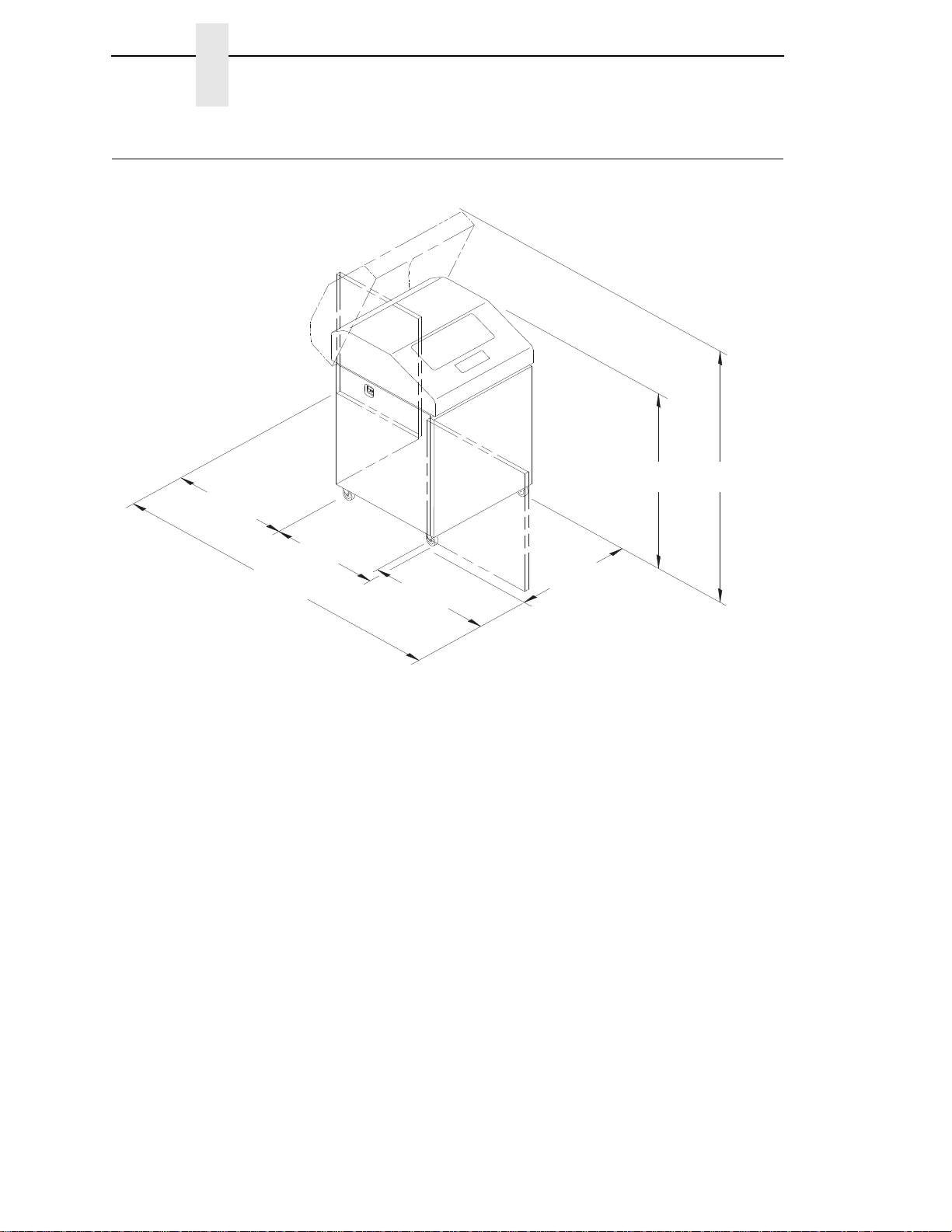
27.0 in
(68.84 cm)
83.0 in
(210.8 cm)
29.0 in
(73.7 cm)
27.0 in
(68.6 cm)
27.0 in
(68.6 cm)
41.0 in
(104 cm)
57.5 in
(146.1 cm)
Printer Dimensions
Printer Dimensions
24
Figure 2. Exploded View Of Cabinet Model Printer Dimensions
Page 25
T
O
F
T
OF
T
O
F
T
O
F
183470b
25 in.
(63.5 cm)
10.5 in.
(26.67 cm.)
48.0 in.
(122 cm)
30 in.
(76.2 cm.)
24.6 in.
(62.48 cm)
Printer Dimensions
Figure 3. Exploded View Of Pedestal Model Printer Dimensions
25
Page 26
Chapter 2
Ribbon Spool
Hub Latch
Blue Tractor
Lock (2)
Paper Support (2)
Tractor (2)
Vertical
Position Knob
Platen Lever
Ribbon Guide (2)
Hammer Bank
Cover and
Ribbon Mask
Ribbon
Splined
Shaft
Platen Stop
Date Code Label
Barcode
Barcode Sensor
Printer Component Locations
Printer Component Locations
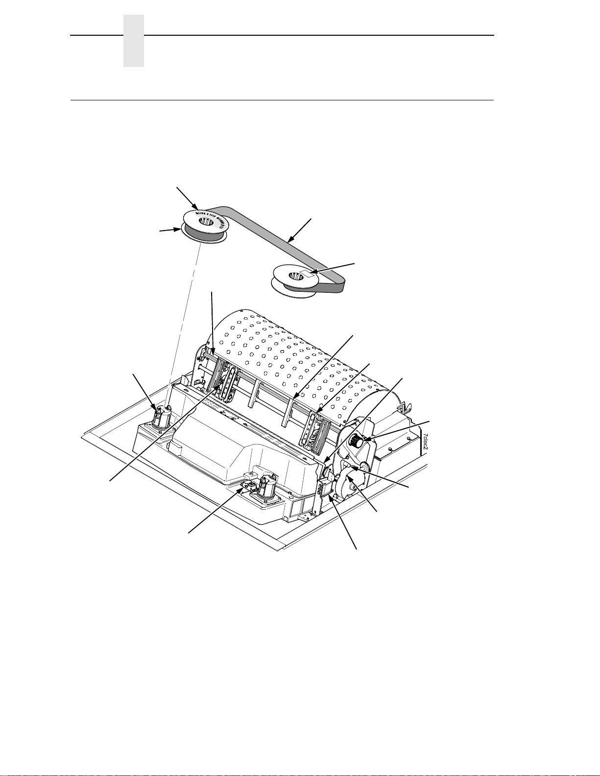
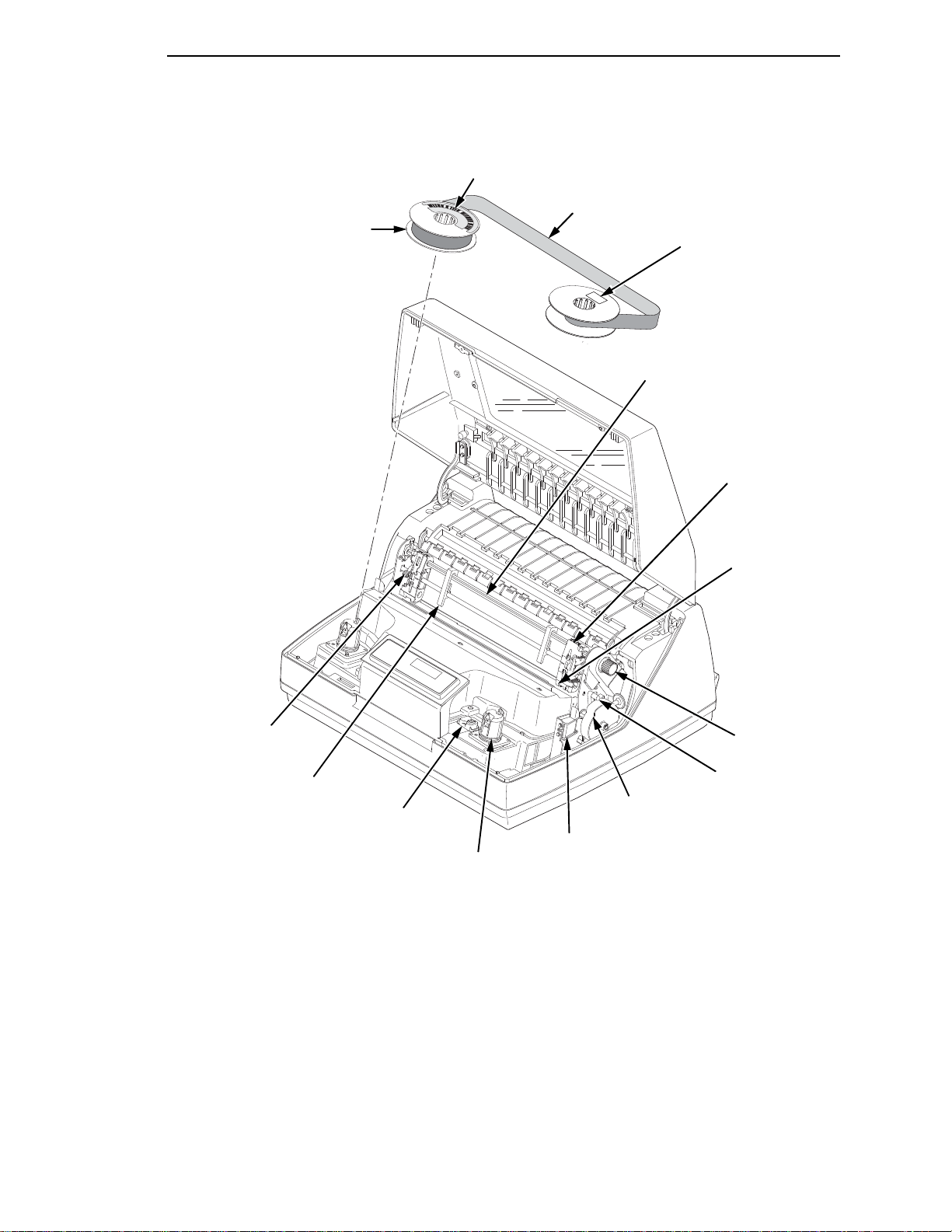
Familiarize yourself with the names and locations of the printer components,
shown in
installation procedures.
Figure 4 and Figure 5 before continuing with the rest of the
Figure 4. 6500-D Printer Component Locations with the Ribbon Spools
Exploded Above
26
Page 27
183471b
T
O
F
T
OF
T
OF
T
O
F
Ribbon Spool
Ribbon Hub
Blue Tractor
Lock (2)
Paper Support (2)
Tractor (2)
Vertical
Position Knob
Platen Lever
Ribbon Guide (2)
Ribbon
Splined Shaft
Platen Stop
Barcode
Hammer Bank
Cover and
Ribbon Mask
Date Code Label
Barcode Sensor
Printer Component Locations
Figure 5. Pedestal Model Printer Component Locations with Open Access Cover and
Ribbon Spools Exploded Above
27
Page 28

Chapter 2
Printer Component Locations
28
Page 29

3
Overview
Configuring the Printer
IMPORTANT
Configuration directly affects printer operation. Do not try to change the
configuration of your printer until you are thoroughly familiar with the
procedures in this chapter.
To print data, the printer must respond correctly to signals and commands
received from the host computer. Configuration is the process of matching the
printer operating characteristics to those of the host computer and to specific
tasks, such as printing labels, or printing on different sizes of paper. The
characteristics that define the printer response to signals and commands
received from the host computer are called configuration parameters.
You can configure the printer by pressing operator panel keys or by sending
control codes from the host computer. This chapter explains how to use the
operator panel to change individual parameters and save them as a custom
configuration.
Your programmer’s reference manuals provide information about control
codes.
The Configurations
A configuration consists of a group of parameters, such as line spacing and
forms length. Your printer contains the following configurations:
•
Four preloaded configurations that have been customized for printer
setup.
•
The factory default configuration. It can be loaded, but it cannot be
altered.
•
Four configurations that you can customize for unique print job
requirements. The process of creating customized configurations is
explained on
page 41.
29
Page 30

Chapter 3
The Configuration Main Menu
Active V ers us Saved Configura tions
When you change a parameter value, it is active as long as the printer is on or
until it is changed again. This is true whether you use the operator panel or
send a control code from the host. Parameter values defined by control codes
override the active operator panel parameters when the printer is using any of
the parallel or serial interfaces. For example, if you set the line spacing to 6 lpi
with the operator panel, and application software later changes this to 8 lpi
with a control code, the control code setting overrides the operator panel
setting.
Using the operator panel, you can save the parameters as a customized
configuration that is stored in non-volatile random access memory (NVRAM).
A saved configuration is not lost when you power off the printer.
NOTE: Saved configurations are also referred to as “custom sets.”
There are no control codes that allow you to save a parameter in NVRAM.
However, you can save a configuration defined partially by control codes and
store it in NVRAM using the operator panel. You can also save configuration
values using PTR_SETUP (see
page 62.)
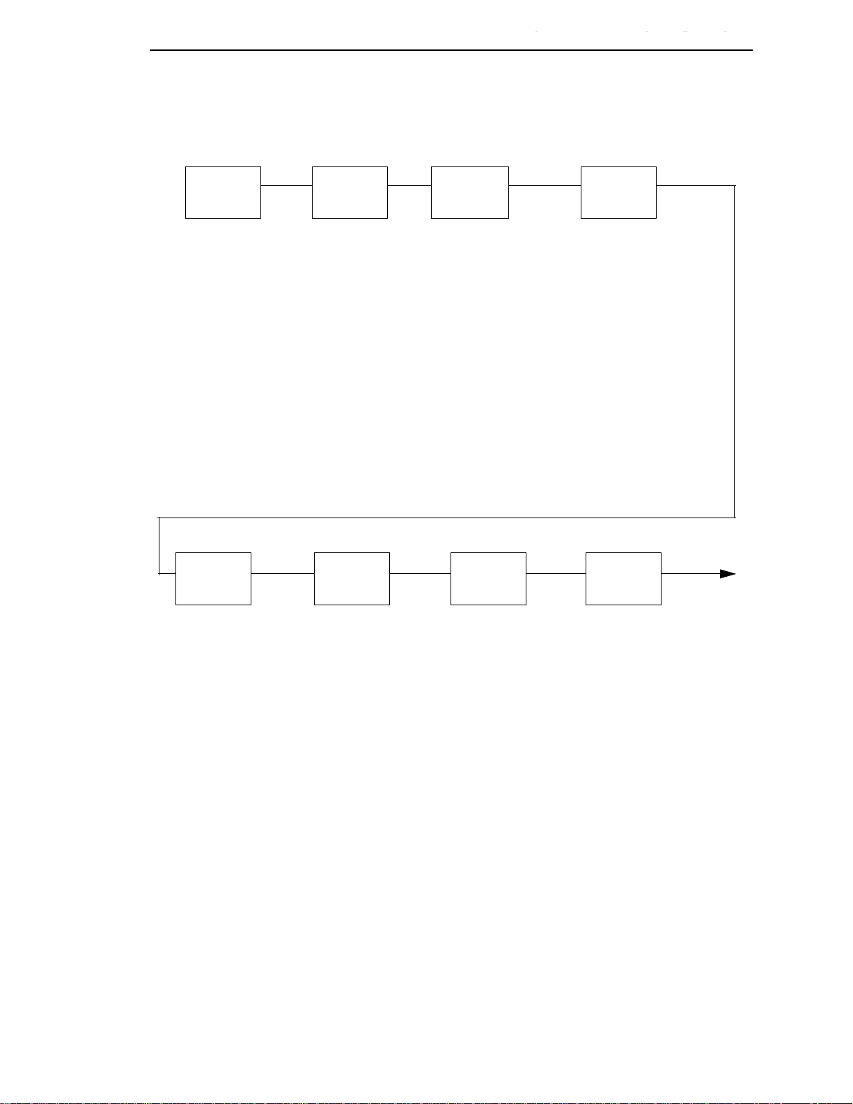
The Configuration Main Menu
Figure 6 shows an overview of the printer configuration menus. The pages
that follow describe how to enter program mode, print the current
configuration, change configuration parameters, and save and load custom
sets.
For specific configuration menu options and their descriptions, refer to
Chapter
NOTE: The menus that are displayed from the operator panel are determined
4, “The Configuration Menus” on page 51.
by the installed features.
Each feature is shipped with a document that describes the feature in
detail. For more information about these documents, see the “Related
Documents” section on
page 12.
30
Page 31
Active Versus Saved Configurations
Printer
Control
page 57
Configuration
Management
page 65
Interface Selection
Display Language
Print Direction
Hex Print Mode
Power On State
Paper Jam Detection
Forms Speed
Set Platen at BOF
Shuttle Timeout
Energy Saver Timer
Eject/Restore
PTR Setup Option
Print DBCS Font File Log
File System
Printer Management Port
Top Exit Tear Distance
Ribbon End Point
Ribbon Action
DBCS Download
1
Recall Custom Set
Save Current Values
Delete Custom Set
Change Power On Set
Protect Custom Sets
Print Custom Set Values
Config Key Default
Name Custom Sets
Reset Custom Set Names
Quick Setup
page 54
Interface Selection
Ethernet Address
Wireless Address
Adapter Address
Graphics Spd Up
Print Quality
DBCS CPI
Lines Per Inch
DBCS ASCII Style
DBCS To ASCII
Ribbon End Point
Reset Command
Recall Custom Set
Save Current Values
Change Power On Set
NOTE:
1
Hanzi GB/Big5 build only
Adapter
Address
page 73
IP Address
Subnet Mask
Gateway Address
MAC Address
DHCP
Ethernet
Address
page 69
IP Address
Subnet
Gateway Address
MAC Address
DHCP
Adapter
Parameters
page 74
Buffer Size in K Byte
Novell Protocol
Nest Serv Type
Netbios Protocol
Novell Frame
ASCII Data Port Number
Keep-Alive Timer
Ethernet Speed
Job Control
Ethernet Hotport
Ethernet
Parameters
page 70
Buffer Size In KBytes
Netbios Protocol
ASCII Data Port
Number
Keep-Alive Timer
Ethernet Speed
Job Control
Ethernet Hotport
Wireless
Address
page 77
IP Address
Subnet Mask
Gateway Address
MAC Address
DHCP
The Configuration Main Menu
Figure 6. Configuration Main Menu
31
Page 32
Chapter 3
Parallel
Interface
page 84
Interface Type
PC Parallel
IEEE 1284
Parallel Hotport
Emulation
Configuration
page 97
ASCII Printer Emulation
Printer Emul Config
Print Format
Operator
Print Tests
page 110
Printer Demonstration*
Print Error Log
Print Ribbon Log
Ripple Print
All E’s
All H’s
All E’s + FF
Underlines
Adapter Test Page
Ethernet Test Page
Clear Error Log
Printer
Information
page 112
Installed Memory
Power On Time
Printing Time
Print Strokes
11 Inch Pages
Serial
Interface
page 91
Interface Type
Data Protocol
Baud Rate
Data Bits
Stop Bits
Parity
Data Terminal Ready
Request To Send
Buffer Size In Kbytes
Poll Character
One Char Enquiry
Serial Hotport
Framing Errors
Wireless
Parameters
page 79
Signal Strength
SSID Name
Reset SSID Name
Operation Mode
Minimum Transfer Rate
Channel
Antenna Diversity
Preamble
Power Management
Transmit Power
International Mode
Authentication Method
Default WEP Key
WEP Key 1
WEP Key 2
WEP Key 3
WEP Key 4
Reset WEP Keys
NOTE:
1
Hanzi GB/Big5 build only
The Configuration Main Menu
32
Figure 64. Configuration Main Menu (con’t)
Page 33
Using The Operator Panel
183963a
SET TOP
OF FORM
FORM
FEED
LINE
FEED
SCROLL/
MICRO
ENTERRETURN
CONFIG
MENU
VIEW CANCEL EJECT START
STOP
SCROLL/
MICRO
Message Display
Status Indicator
Figure 7. The Operator Panel
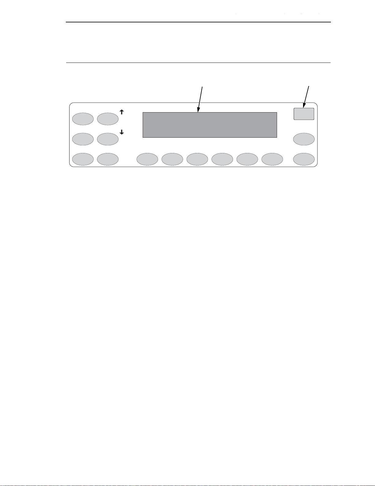
The operator panel is shown above. During the configuration process, you will
use the SCROLL/MICRO, SCROLL/MICRO, ENTER, and RETURN keys
on the operator panel to access configuration settings and diagnostic tests via
the configuration menus. As you access menus and options, menu names
and option values appear on the operator panel message display
(someTimes New Roman referred to as LCD, or Liquid Crystal Display).
Active Versus Saved Configurations
Using The Operator Panel
This chapter provides numerous examples of how to use the operator panel
keys and indicator message display to configure the printer.
Message Display
An alphanumeric LCD display consists of a minimum of two rows of twentyfour characters each used to display printer status, fault messages, and
menus to permit the operator to set various configurations. The display can be
set to any one of the following languages: English, French, German, Italian,
Spanish, Dutch, Brazilian-Portuguese, and Polish.
Sta tus Indicator
A high visibility light for indicating general printer status. The light is on when
the printer is READY (on-line to the host), off when the printer is NOT READY
(off-line), or flashes if a fault condition exists.
Control Panel Overlay
An adhesive-backed overlay is provided that adheres to the face of the control
panel. Overlays are provided in the following languages: English, French,
German, Italian, Spanish, Dutch, Brazilian-Portuguese, and Polish. The
overlay legends can be translated into additional languages as required.
33
Page 34

Chapter 3
Using The Operator Panel
Switch Functionality
Fourteen keys are provided for selecting and controlling printer features and
options.
START Use the START key to place the printer in the READY (on-line)
state if it is off-line. Pressing Start in the Program mode exits the
menus and places the printer in the READY state. After pressing
View or Eject to move the print position to the tractor area,
pressing the START key moves the paper back to its original print
position, and places the printer in the READY state.
STOP Use the STOP key to place the printer in the NOT READY
(off-line) state if it is on-line. When a fault condition exists,
pressing STOP clears the fault and places the printer in the NOT
READY state. After pressing VIEW or EJECT to move the print
position to the tractor area, pressing Stop moves the paper back
to its original print position and places the printer in the NOT
READY state.
MENU The MENU key operates only in the NOT READY state and is
used to display the printers control menu. Press MENU
repeatedly to view the menus without changing any settings. No
configuration changes can be made when the Program state is
locked. To change the configuration settings, press the RETURN
and ENTER keys at the same time to unlock the Program state,
then press MENU. The menu is then viewed using the
SCROLL/MICRO, SCROLL/MICRO, and the RETURN and
ENTER keys. When the Program state is unlocked, new values
may be selected from the menus using the ENTER key.
CONFIG (Printer configuration) The CONFIG key operates only in the NOT
READY state. Pressing CONFIG prints the currently selected
configuration. Pressing the STOP key stops printing and returns
to NOT READY.
RETURN The RETURN key operates only in the NOT READY state. In the
Program state, it causes the display to move to a higher level in
the menu structure.
Pressing the RETURN and ENTER keys at the same time
unlocks the ENTER key when in the Program state.
SCROLL/MICRO
Pressing the SCROLL/MICRO key in the READY state has no
effect and returns the message “INVALID KEY PRESS”. In the
NOT READY state, this key micro–steps the paper upward in 1/
72 inch increments. Press and hold the key to move paper at 10
increments per second. In the MENU state, pressing SCROLL/
MICRO navigates the menu and does not move the paper.
34
Page 35

Active Versus Saved Configurations
SCROLL/MICRO
Pressing the SCROLL/MICRO key in the READY state has no
effect and returns the message “INVALID KEY PRESS”. In the
NOT READY state, this key micro–steps the paper downward in
1/72 inch increments. Press and hold the key to move paper at 10
increments per second. When in the MENU state, pressing this
key navigates the menu and does not move the paper.
ENTER The ENTER key operates only in the NOT READY state.
•
In the Program state it moves the display to a lower level in
the menu structure.
•
In the unlocked Program state it selects a configuration
option value.
•
In the Program state it starts and stops a Print Test selected
from the Operator Print Tests menu.
•
In the NOT READY state pressing STOP and ENTER
performs a soft reset of the printer which resets the printer to
the Power On configuration.
Using The Operator Panel
Pressing the ENTER and STOP keys at the same time while the
printer is in the NOT READY state causes a soft reset.
Pressing the RETURN and ENTER keys at the same time
unlocks the ENTER key when in the Program state.
LINE FEED
Pressing the LINE FEED key when in the NOT READY state,
prints any data in the buffer and then moves the paper. Data not
in the buffer is not affected. The initial paper motion is one line at
the currently defined line spacing. LINE FEED repeats if the key
is continually held down.
VIEW Pressing the VIEW key in the NOT READY state moves the
paper from the current print position up to the tractor area for
viewing. If there is any data left in the print buffer, it is printed and
then the paper moves up for viewing. Pressing VIEW a second
time or pressing START or STOP returns the paper to its original
print position.
FORM FEED
Pressing and releasing the FORM FEED key in the NOT READY
state moves the paper to the top–of–form on the next page. If
there is any data in the print buffer, it prints first and then the
paper moves to the next top–of–form. Data not in the print buffer
is not affected. Press the FORM FEED key in the Fault state to
silence the alarm and cause the paper to move. The top–of–form
setting is lost.
35
Page 36

Chapter 3
Using The Operator Panel
SET TOP OF FORM
Pressing the SET TOP OF FORM key in the NOT READY state,
unless there is data in the buffer, moves the paper downward
relative from the TOF alignment index to the print station and sets
this position to be the top of form. Positions the TOF correctly,
independent of the form length. If there is data in the buffers, this
data is printed and then the printer slews to the place on the page
where the printing left off.
CANCEL Pressing the CANCEL key clears all of the data in the print buffer.
This key can be disabled in the menus. The CANCEL key is not
active during VIEW and EJECT operations. The CANCEL key
does the following:
1. Stops printer tests in progress.
2. Cancels a print job. This operation depends on the printer
interface.
Coax Interface (non-SCS mode)
The CANCEL key is not effective and the “009
INVALID KEY” error message displays.
Note: With a Coax Interface, press the CANCEL
key a second time to stop the previous cancel.
Coax Interface (SCS mode)
Effective in the NOT READY state, but the action
occurs only in the READY state. When pressed, the
“059 CANCEL PRINT ACTIVE” message is
displayed.
Twinax Interface
Effective in the READY and NOT READY states.
When pressed, the “059 CANCEL PRINT ACTIVE”
message is displayed.
IPDS Interface
Ethernet (IPDS mode): Effective in the NOT
READY state. The two forms of cancel are:
a. Full Cancel: A CANCEL command is sent to the
host requesting that the print job be cancelled and
the next job in the queue be submitted for printing.
This is done by pressing the CANCEL key twice.
When pressed, the “059 CANCEL PRINT ACTIVE”
message is displayed.
36
b. Clear Buffers: A Clear Buffers command is sent
to the host informing the host that the printer has
cleared its buffers. At this point, the job can be
restarted from any page based on the instruction
from the host. This is done by pressing the
CANCEL key once, then pressing the STOP key.
When pressed, the “069 DATA CLEARED”
message is displayed.
Page 37

Active Versus Saved Configurations
Serial/Parallel/Ethernet Interface
We recommend that you stop the print job from the
host system before you press CANCEL. Effective in
the NOT READY state. When pressed, the “069
DATA CLEARED” message is displayed.
EJECT The EJECT key has two modes of operation. Standard mode is
the only mode available on the cabinet models. For pedestal
models (without zero tear option), the Standard mode can be
selected from the menu and should be selected when using the
rear paper exit. In Standard mode, the EJECT key moves the
paper forward to facilitate tearing off the paper at the perforation
then restores the original paper position. Once the paper is torn
at the perforation, pressing either the EJECT, START, or Stop
keys retracts the paper to its previous position, as described
below:
EJECT Moves the paper to its previous position. The
printer returns to the mode it was in before EJECT
was used.
START Moves the paper to its previous position and places
the printer in the READY state.
Using The Operator Panel
STOP Moves the paper to its previous position and places
the printer in the NOT READY state.
If the paper is to be torn off, the FORM FEED key must be
pressed before pressing the EJECT, START, or STOP keys. This
feeds an additional page first and prevents the paper from
unloading when it is restored to its original position after the form
is torn off.
For pedestal models (without zero tear option), in the Top Exit
Tear mode (selectable at the operator panel), this key moves the
paper to the top of the next form. In the NOT READY state,
pressing the EJECT key moves the paper forward to the tear–off
position. In the NOT READY state, pressing the EJECT key
moves the paper forward to the tear–off position. Pressing one of
the following keys has the function described below:
EJECT Moves the paper to its next available position. The
printer returns to the mode it was in before EJECT
was pressed.
START Moves the paper to its next available position and
places the printer in the READY state.
STOP Moves the paper to its previous position and places
the printer in the NOT READY state.
37
Page 38

Chapter 3
OPERATOR MENU
UNLOCKED
OPERATOR MENU
LOCKED
Program Mode
Program Mode
The printer is in Program mode whenever the configuration menus and option
values are displayed on the operator panel message display. Program mode
is either locked or unlocked. In order to select new configuration values, you
must unlock Program mode. In order to prevent accidental changing of the
configuration settings, you may lock Program mode.
Unlocking The Program Mo de
To use the operator panel to change the configuration settings, Program
mode must be unlocked. When Program mode is unlocked, pressing the
Enter key selects configuration values as the active values, that is, places
them into printer DRAM. An asterisk (*) after a displayed setting shows it is
entered into memory.
Press the RETURN + ENTER keys at the same time to unlock Program
mode. The following message will appear briefly:
Locking The Program Mode
When Program mode is locked, you cannot use the operator panel to change
the configuration settings. However, you can still select the configuration
menus and view the current configuration settings.
Press the RETURN + ENTER keys at the same time to lock Program mode.
The following message will appear briefly:
Entering Program Mode
To place the printer in Program mode, press the MENU key.
38
Page 39
STOP
CONFIG
START
START
Printing The Current Configuration
Entering Program Mode
Printing The Current Co nfiguration
Step Key LCD Result Notes
1. Make sure the printer is on
2. Press NOT READY The printer must be in NOT
READY mode to print the
configuration.
3. PRESS START TO PRINT
PRESS STOP TO EXIT
4. NOT READY Indicates that the configuration
5. READY The printer is READY for normal
The second method for printing the current configuration, as well as several
other configurations, is to use the Print Custom Set Values menu option,
shown on the following page.
You are prompted to press the
Start key before the
configuration prints.
has printed. Date and store the
printout in a safe place. You may
also want to label the printout
(e.g. “Configuration for 2-up
Labels”).
operation.
39
Page 40
Chapter 3
Configuration
Management
Recall
Custom Set
Protect
Custom Sets
Change
Power
On Set
Delete
Custom Set
Save Current
Values
Print Custom
Set Values
Current Custom Set*
Factory Default
Power On Custom Set
All Custom Sets
Custom Set 1
Custom Set 2
Custom Set 3
Custom Set 4
Custom/Preload Set 5
Custom/Preload Set 6
Custom/Preload Set 7
Custom/Preload Set 8
Current Quick Setup
* = Factory Default
Name
Custom Sets
Reset
Custom Set
Names
Config Key
Default
Printing The Current Configuration
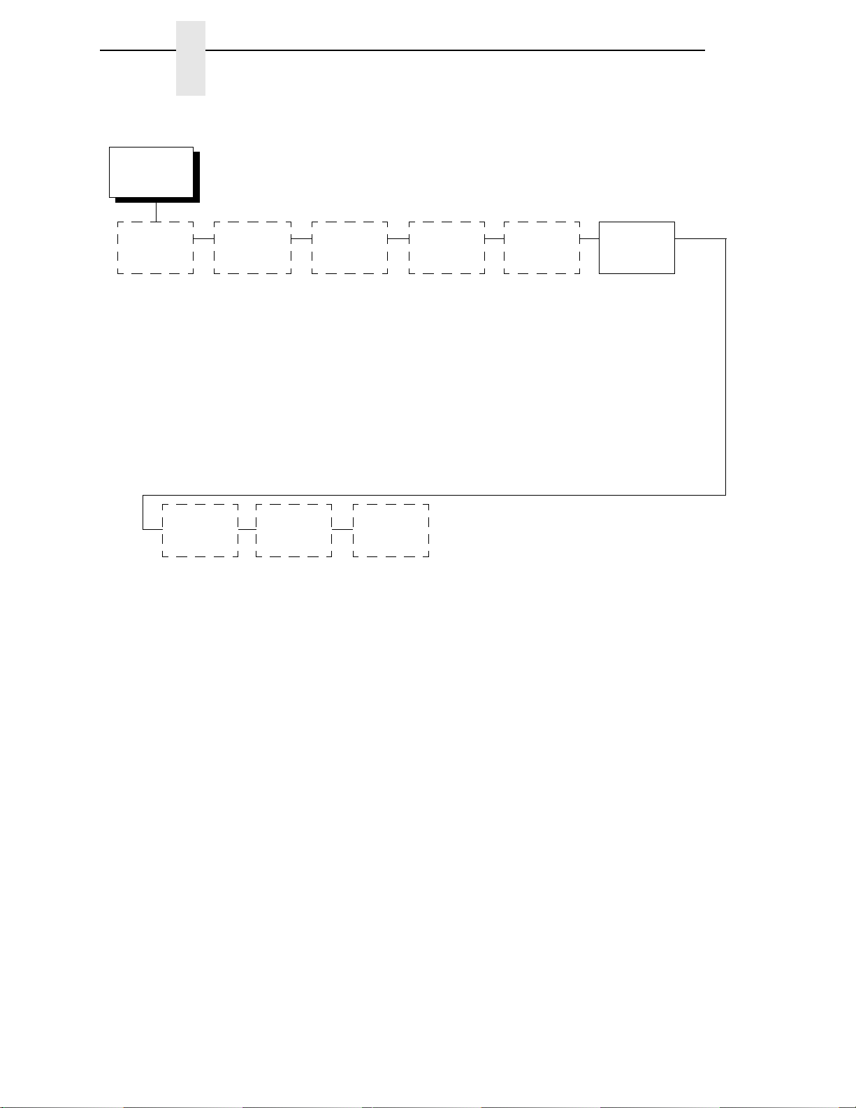
The Print Custom Set Values selection on the Configuration Management
menu allows you to print any or all of the configurations shown above. The
default setting, “Current Custom Set,” will print the same information as
pressing the Printer Configuration key. The Current Custom Set is the Power
On configuration until you begin modifying the printer configuration.
Custom sets 1 through 4 do not exist until you save configuration parameters
to them. You must define and save a custom set before you can print it.
The other options will only be useful once you have modified and saved the
printer configuration parameter settings.
The Power On Custom Set is defined by the “Change Power On Set” option.
Custom Sets 1 through 8 are defined by the “Save Current Values” option.
These options are described in detail under the Configuration Management
Menu description starting on
page 65.
40
Page 41
Changing Parame ters
Printer
Control
Interface
Selection
Hex Print
Mode
Print
Direction
Display
Language
Bidirectional*
Unidirectional
* = Factory Default
STOP
RETURN ENTER
+
MENU
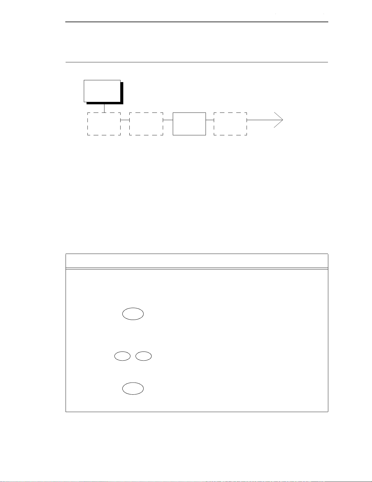
The following procedure shows you how to change a configuration setting.
Changing the Print Direction from the factory default setting BIDIRECTIONAL
to the setting UNIDIRECTIONAL is provided as an example. Print Direction is
one of the Printer Control menu options. The procedure is similar for other
configuration changes. Use these basic guidelines to navigate the
configuration menus and change other parameters.
Changing Parameters
Entering Program Mode
NOTE: Press Start at any time to exit the configuration menu.
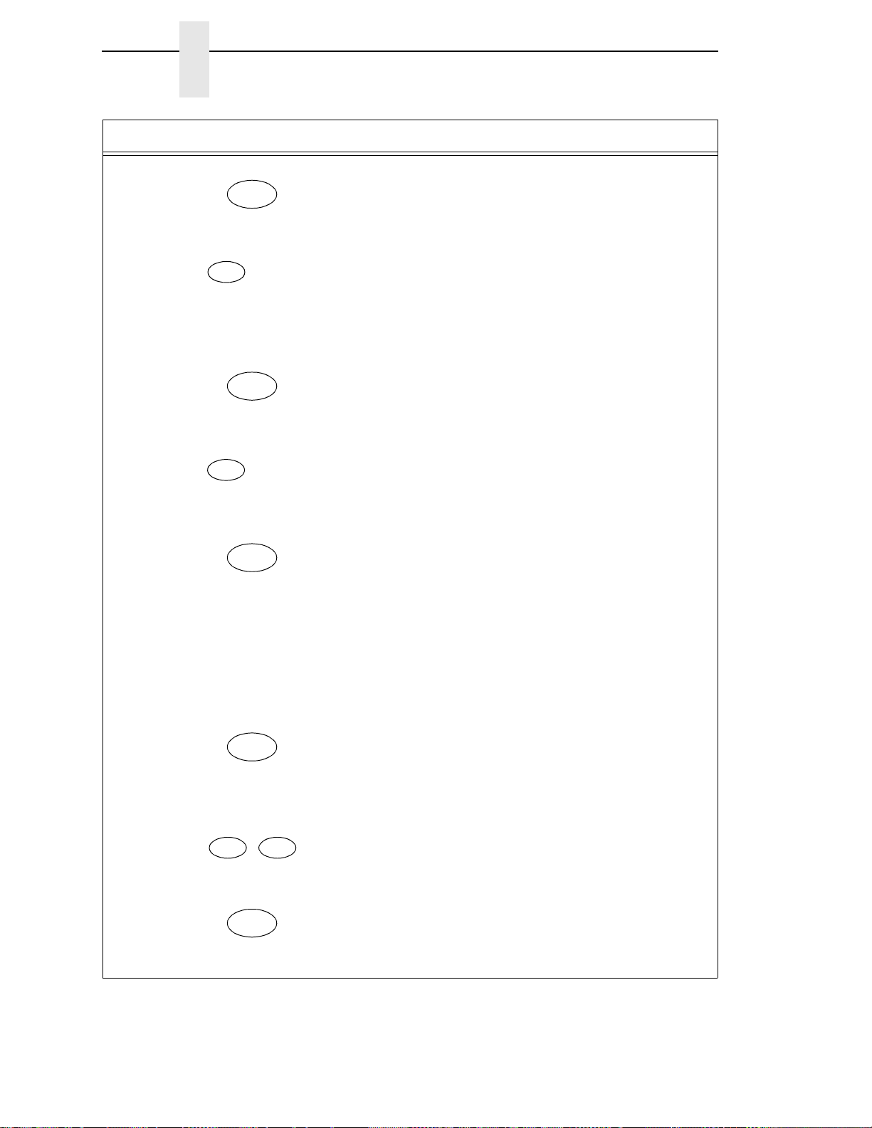
Step Key LCD Results Notes
1. Determine which parameters you want to change and what the new values will be. In this
example, the value for the PRINT DIRECTION parameter will be changed from
“BIDIRECTIONAL” to “UNIDIRECTIONAL.”
2. Press NOT READY Places the printer in NOT
READY mode before entering
the operator menus.
3. OPERATOR MENU
UNLOCKED
Unlocks the Operator Menu,
which allows you to make
configuration changes.
4. OPERATOR MENU
PRINTER CONTROL
Displays the first Configuration
Main Menu option, PRINTER
CONTROL.
41
Page 42
Chapter 3
ENTER
SCROLL/
MICRO
UNTIL
ENTER
SCROLL/
MICRO
ENTER
STOP
RETURN ENTER
+
STOP
Changing Parameters
Step Key LCD Results Notes
5. PRINTER CONTROL
INTERFACE SELECTION
6. PRINTER CONTROL
PRINT DIRECTION
7. PRINT DIRECTION
BIDIRECTIONAL*
8. PRINT DIRECTION
UNIDIRECTIONAL
9. PRINT DIRECTION
UNIDIRECTIONAL*
Moves into the PRINTER
CONTROL menu.
Moves to the PRINT
DIRECTION parameter.
Move into the PRINT
DIRECTION menu. The asterisk
(*) shows that this is the active
value.
Moves to the next available
option, the UNIDIRECTIONAL
option.
Selects the displayed value. An
asterisk (*) appears indicating
that this choice is now the active
value.
10. Continue this pattern to make all of the changes, using the information in this chapter.
11. To save changes so that they will remain when the printer is reset or powered back on, see
“Saving Your Configuration In A Custom Set” on page 43. If you want to use these values
without saving, continue to the next step.
12. NOT READY Returns the printer to the NOT
READY mode.
13. OPERATOR MENU
LOCKED
Locks Program mode and the
Operator Menu.
14. READY Places the printer in READY
mode, prepared for normal
operation.
42
Page 43
Configuration
Management
Recall
Custom Set
Protect
Custom Sets
Change
Power On Set
Delete
Custom Set
Save Current
Values
1*
2
3
4
5
6
7
8
* = Factory Default
Print Custom
Set Values
Name
Custom Sets
Reset
Custom Set
Names
Saving Your Configuration In A Custom Set
Saving Your Configuration In A Custom Set
Entering Program Mode
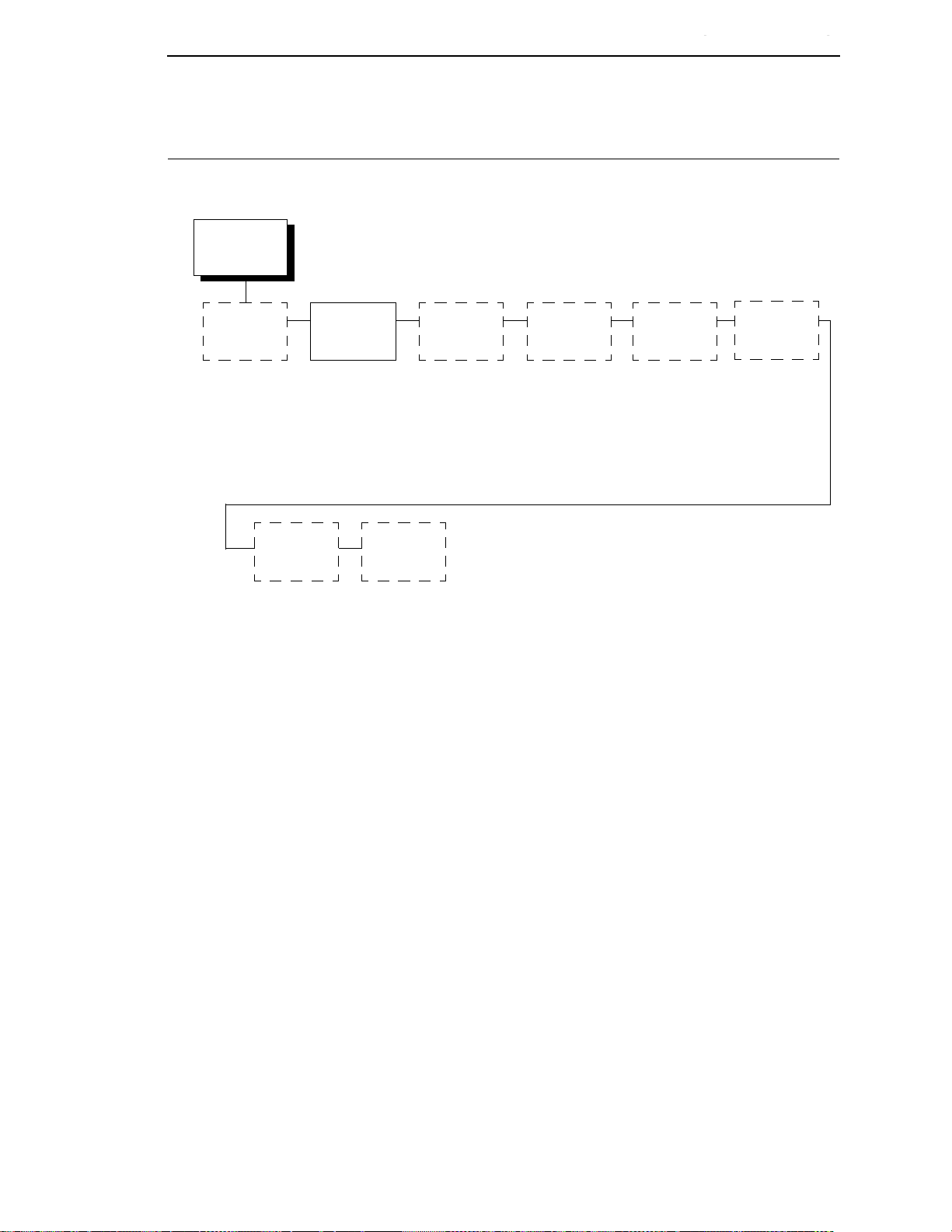
Once you have changed all of the necessary parameters, it is recommended
you save them as a configuration that can be stored and loaded later for
future use. You can save your configurations to meet different print job
requirements.
The saved configurations (called custom sets) are stored in NVRAM—they
will not be lost if you power off the printer.
Later, you can load one of the configurations for a specific print job. This
eliminates the need to change settings, such as CPI and LPI, for each new
job. See
You may want to print records of your configurations (see page 39) and store
them in a safe place, such as inside the printer cabinet.
page 46 for details on loading configurations.
43
Page 44
Chapter 3
STOP
RETURN ENTER
+
MENU
SCROLL/
MICRO
UNTIL
ENTER
SCROLL/
MICRO
UNTIL
ENTER
Saving Your Configuration In A Custom Set
If you do not save your configuration before you power off the printer, all of the
new parameter values that have not been saved to NVRAM will be erased.
When you power the printer on again, the power-on configuration will load. If
no configuration has been designated as the power-on configuration, the
factory configuration will load.
NOTE: To avoid overwriting an existing custom set, the Protect Custom Sets
parameter must be set to ENABLE. See
page 68 for details.
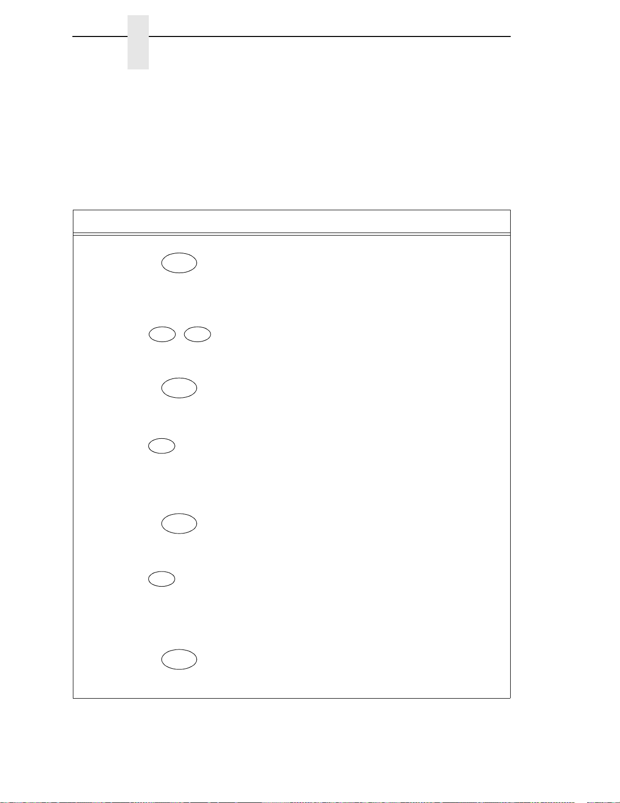
Step Key LCD Results Notes
1. Press NOT READY Places the printer in NOT
READY mode.
2. OPERATOR MENU
UNLOCKED
3. OPERATOR MENU
PRINTER CONTROL
4. OPERATOR MENU
CONFIGURATION
MANAGEMENT
5. CONFIGURATION
MANAGEMENT
RECALL CUSTOM SET
6. CONFIGURATION
MANAGEMENT
SAVE CURRENT
VALUES
Unlocks the Operator Menu,
which allows you to make
configuration changes.
Displays the first Configuration
Main Menu option, PRINTER
CONTROL.
Moves to the Configuration
Management menu option.
Selects the CONFIGURATION
MANAGEMENT menu. The
RECALL CUSTOM SET option
appears.
Moves to the SAVE CURRENT
VALUES option.
7. SAVE CURRENT
VALUES
1*
44
Selects the SAVE CURRENT
VALUES menu.
Page 45
SCROLL/
MICRO
UNTIL
ENTER
STOP
RETURN ENTER
+
STOP
Saving Your Configuration In A Custom Set
Entering Program Mode
Step Key LCD Results Notes
8. SAVE CURRENT
VALUES
Scrolls through the list of custom
sets 1 - 8.
2
9. SAVING
CONFIGURATION
Selects the SAVE CURRENT
VALUES option. The message
“SAVING CONFIGURATION”
appears briefly.
10. NOT READY Returns the printer to the NOT
READY mode.
11. OPERATOR MENU
LOCKED
Locks Program mode and the
Operator Menu.
12. READY Places the printer in READY
mode, prepared for normal
operation.
13. It is recommended you print your current configuration, as described on page 39.
45
Page 46
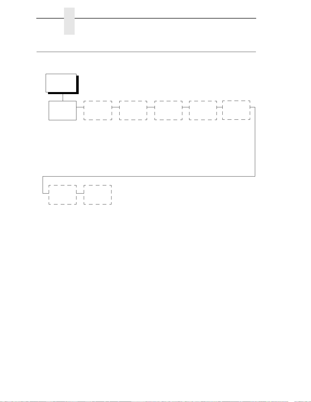
Chapter 3
Configuration
Management
Recall
Custom Set
Factory Default*
Custom Set 1
Custom Set 2
Custom Set 3
Custom Set 4
Custom/Preload Set 5
Custom/Preload Set 6
Custom/Preload Set 7
Custom/Preload Set 8
Protect
Custom Sets
Change
Power On Set
Delete
Custom Set
Save Current
Values
* = Factory Default
Print Custom
Set Values
Name
Custom Sets
Reset
Custom Set
Names
Loading Custom Sets Or Factory Default Values
Loading Custom Set s Or Fa ctory Default Values
You can load any of the custom set configurations or the factory default
configuration. The loaded configuration remains active as long as the printer
is on. The following procedure shows how to load factory defaults to the
printer.
If you power off the printer, the power-on configuration will load the next time
the printer is powered on. Selecting the power-on configuration is explained
page 48.
on
46
Page 47
STOP
RETURN ENTER
+
MENU
SCROLL/
MICRO
UNTIL
ENTER
ENTER
ENTER
STOP
RETURN ENTER
+
Loading Custom Sets Or Factory Default Values
Entering Program Mode
Step Key LCD Results Notes
1. Press NOT READY Places the printer in NOT
READY mode.
2. OPERATOR MENU
UNLOCKED
3. OPERATOR MENU
PRINTER CONTROL
4. OPERATOR MENU
CONFIGURATION
MANAGEMENT
5. CONFIGURATION
MANAGEMENT
RECALL CUSTOM SET
6. RECALL CUSTOM SET
FACTORY DEFAULT
Unlocks the Operator Menu,
which allows you to make
configuration changes.
Displays the first Configuration
Main Menu option, PRINTER
CONTROL.
Moves to the Configuration
Management menu option.
Selects the CONFIGURATION
MANAGEMENT menu. The
RECALL CUSTOM SET option
appears.
Moves forward to the FACTORY
DEFAULT parameter for the
RECALL CUSTOM SET option.
7. LOADING SAVED
CONFIGURATION
Loads the set of Factory Default
values. The message “LOADING
SAVED CONFIGURATION”
appears briefly.
8. NOT READY Returns the printer to the NOT
READY mode.
9. OPERATOR MENU
LOCKED
Locks Program mode and the
Operator Menu.
47
Page 48
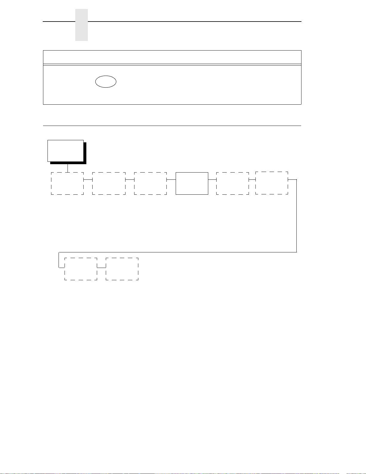
Chapter 3
STOP
Configuration
Management
Recall
Custom Set
Protect
Custom Sets
Change
Power On Set
Delete
Custom Set
Save Current
Values
Factory Default*
Custom Set 1
Custom Set 2
Custom Set 3
Custom Set 4
Custom/Preload Set 5
Custom/Preload Set 6
Custom/Preload Set 7
Custom/Preload Set 8
* = Factory Default
Print Custom
Set Values
Name
Custom Sets
Reset
Custom Set
Names
Changing The Power On Configuration
Step Key LCD Results Notes
10. READY Places the printer in READY
mode, prepared for normal
operation.
Changing The Power On Configuration
48
When you power on the printer for the first time, it loads the factory default
configuration. If you power the printer off and then back on, the printer will
load the designated power-on configuration (which is set to Factory Default by
default). It will not load the last saved configuration.
The Change Power On Set option allows you to select a custom set of
configuration values as the power-on configuration. The example on the
following page shows how to select Custom Set 1 as the power-on
configuration.
NOTE: Be sure you define and save a custom set before attempting to use it
as the Power On Custom Set. Otherwise, the current Power On
Custom Set remains selected and the following operator panel
message is displayed:
For example, if you attempt to change the Power On Custom Set
from Custom Set 1 to Custom Set 4, and if Custom Set 4 does not
exist, Custom Set 1 remains the Power On Custom Set.
042 CUSTOM SET DOES NOT EXIST
SAVE FIRST
Page 49
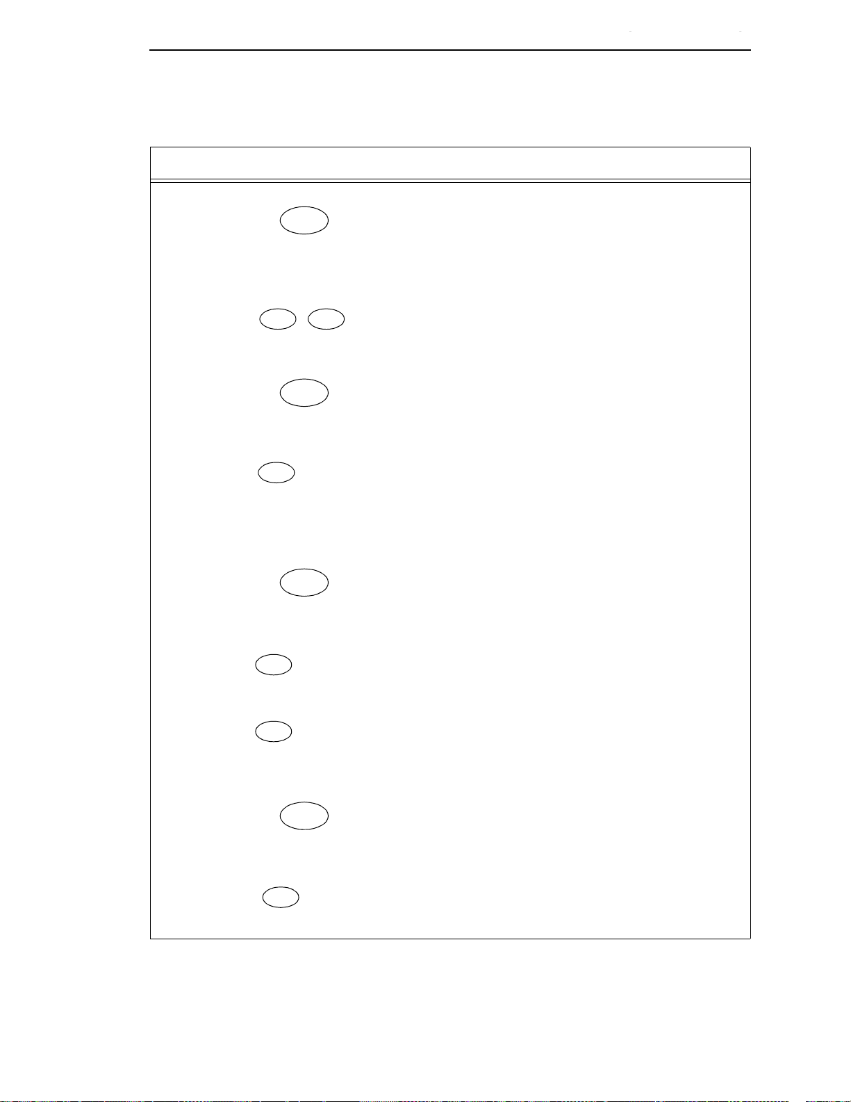
STOP
RETURN ENTER
+
MENU
SCROLL/
MICRO
UNTIL
ENTER
SCROLL/
MICRO
SCROLL/
MICRO
OR
ENTER
SCROLL/
MICRO
Changing The Power On Configuration
Entering Program Mode
Step Key LCD Results Notes
1. Press NOT READY Places the printer in NOT
READY mode.
2. OPERATOR MENU
UNLOCKED
3. OPERATOR MENU
PRINTER CONTROL
4. OPERATOR MENU
CONFIGURATION
MANAGEMENT
5. CONFIGURATION
MANAGEMENT
RECALL CUSTOM SET
6. CONFIGURATION
MANAGEMENT
CHANGE POWER ON
SET
Unlocks the Operator Menu,
which allows you to make
configuration changes.
Displays the first Configuration
Main Menu option, PRINTER
CONTROL.
Moves to the Configuration
Management menu option.
Selects the CONFIGURATION
MANAGEMENT menu. The
RECALL CUSTOM SET option
appears.
Moves to the CHANGE POWER
SET ON parameter.
7. CHANGE POWER ON
SET
FACTORY DEFAULT
8. CHANGE POWER ON
SET
CUSTOM SET 1
Displays the first POWER ON
SET option, FACTORY
DEFAULT.
Displays CUSTOM SET 1 as the
POWER ON SET option value.
49
Page 50
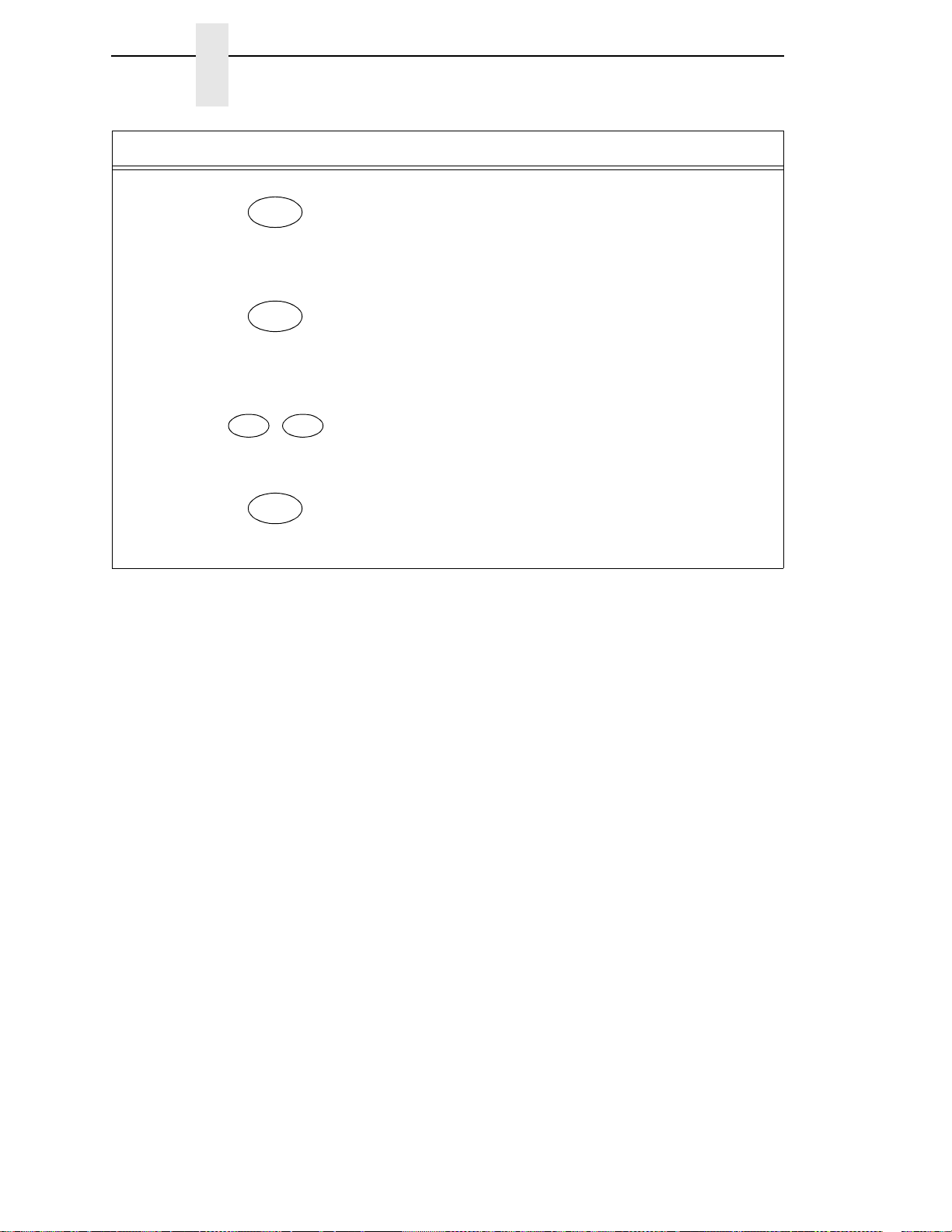
Chapter 3
ENTER
STOP
RETURN ENTER
+
STOP
Changing The Power On Configuration
Step Key LCD Results Notes
9. CHANGE POWER ON
SET
An asterisk (*) appears after the
change is complete.
CUSTOM SET 1*
10. NOT READY Returns the printer to the NOT
READY mode.
11. OPERATOR MENU
LOCKED
Locks Program mode and the
Operator Menu.
12. READY Places the printer in READY
mode, prepared for normal
operation.
50
Page 51

4
The Configuration Menus
Configuration Overview
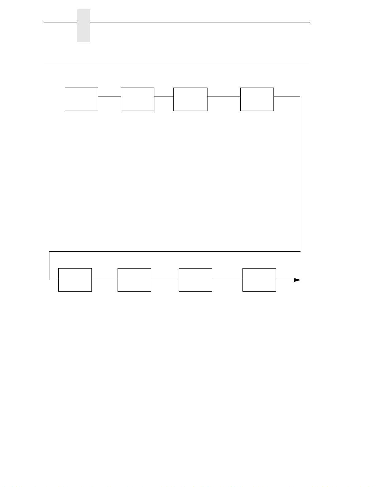
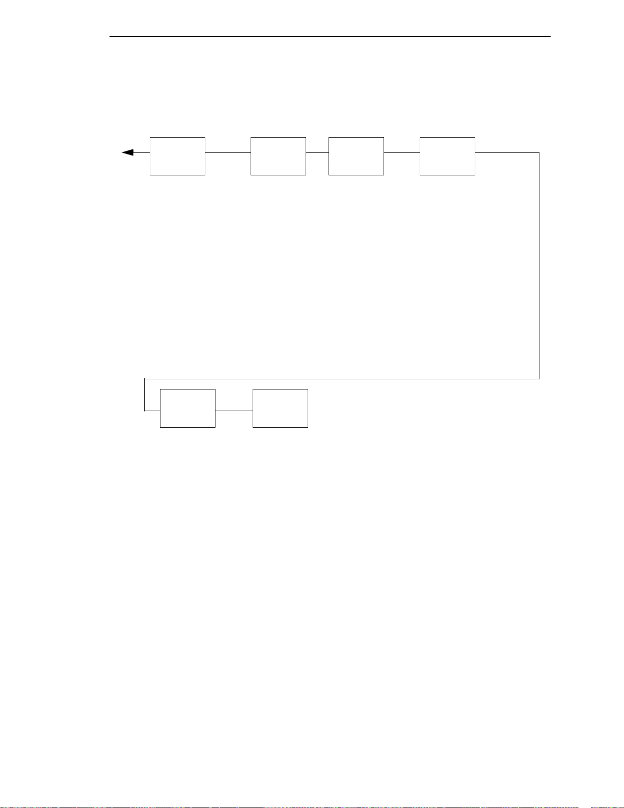
This chapter describes the configuration menus. The Configuration Main
Menu options and all of the submenu options are illustrated in menu diagrams
and described in detail. For procedures showing how to enter Program mode,
save, recall, and print configurations, refer to Chapter
Printer” on page 29.
Figure 8 shows an overview of the configuration menus.
The configuration menu diagram on page 52 shows the structure of the
configuration menus and the parameter options available in each menu. The
diagrams list the menus and options in the order they appear when you use
the operator panel to configure the printer. Factory default configuration
values are indicated by an asterisk (
Pressing the operator panel keys (ENTER, RETURN, SCROLL/MICRO
and SCROLL/MICRO allows you to move through the menus and select
various choices for the options, as follows:
3, “Configuring the
*
).
•
The ENTER key allows you to move down to a lower level in the menu
structure, and to select an option value as the active value.
•
The RETURN key moves you back up the menu structure.
•
The SCROLL/MICRO key moves forward through the options at a
particular menu level.
•
The SCROLL/MICRO key moves backward through the options at a
particular menu level.
These keys are summarized in a legend box at the lower right corner of each
configuration menu diagram.
51
Page 52
Chapter 4
Printer
Control
page 57
Configuration
Management
page 65
Interface Selection
Display Language
Print Direction
Hex Print Mode
Power On State
Paper Jam Detection
Forms Speed
Set Platen at BOF
Shuttle Timeout
Energy Saver Timer
Eject/Restore
PTR Setup Option
Print DBCS Font File Log
File System
Printer Management Port
Top Exit Tear Distance
Ribbon End Point
Ribbon Action
Print DBCS Font File Log
DBCS Download
1
Recall Custom Set
Save Current Values
Delete Custom Set
Change Power On Set
Protect Custom Sets
Print Custom Set Values
Config Key Default
Name Custom Sets
Reset Custom Set Names
Quick Setup
page 54
Interface Selection
Ethernet Address
Wireless Address
Adapter Address
Graphics Spd Up
Print Quality
DBCS CPI
Lines Per Inch
DBCS ASCII Style
DBCS To ASCII
Ribbon End Point
Reset Command
Recall Custom Set
Save Current Vaues
Change Power On Set
NOTE:
1
Hanzi GB/Big5 build only
Ethernet
Address
page 69
IP Address
Subnet
Gateway Address
MAC Address
DHCP
Adapter
Address
page 73
IP Address
Subnet Mask
Gateway Address
MAC Address
DHCP
Adapter
Parameters
page 74
Buffer Size in KBytes
Novell Protocol
Nest Serv Type
Netbios Protocol
Novell Frame
ASCII Data Port Number
Keep-Alive Timer
Ethernet Speed
Job Control
Ethernet Hotport
Ethernet
Parameters
page 70
Buffer Size In KBytes
Netbios Protocol
ASCII Data Port Number
Keep-Alive Timer
Ethernet Speed
Job Control
Ethernet Hotport
Wireless
Address
page 77
IP Address
Subnet Mask
Gateway Address
MAC Address
DHCP
Main Menu
Main Menu
52
Figure 8. 6500-D Series Main Menu Configuration
Page 53
Parallel
Interface
page 84
Interface Type
PC Parallel
IEEE 1284
Parallel Hotport
Emulation
Configuration
page 97
ASCII Printer Emulation
Printer Emul Config
Print Format
Operator
Print Tests
page 110
Printer Demonstration*
Print Error Log
Print Ribbon Log
Ripple Print
All E’s
All H’s
All E’s + FF
Underlines
Adapter Test Page
Ethernet Test Page
Clear Error Log
Printer
Information
page 112
Installed Memory
Power On Time
Printing Time
Print Strokes
11 Inch Pages
Serial
Interface
page 91
Interface Type
Data Protocol
Baud Rate
Data Bits
Stop Bits
Parity
Data Terminal Ready
Request To Send
Buffer Size In Kbytes
Poll Character
One Char Enquiry
Serial Hotport
Framing Errors
Wireless
Parameters
page 79
Signal Strength
SSID Name
Reset SSID Name
Operation Mode
Minimum Transfer Rate
Channel
Antenna Diversity
Preamble
Power Management
Transmit Power
International Mode
Authorization Method
Default WEP Key
WEP Key 1
WEP Key 2
WEP Key 3
WEP Key 4
Reset WEP Keys
NOTE:
1
Hanzi GB/Big5 build only
Main Menu
53
Page 54
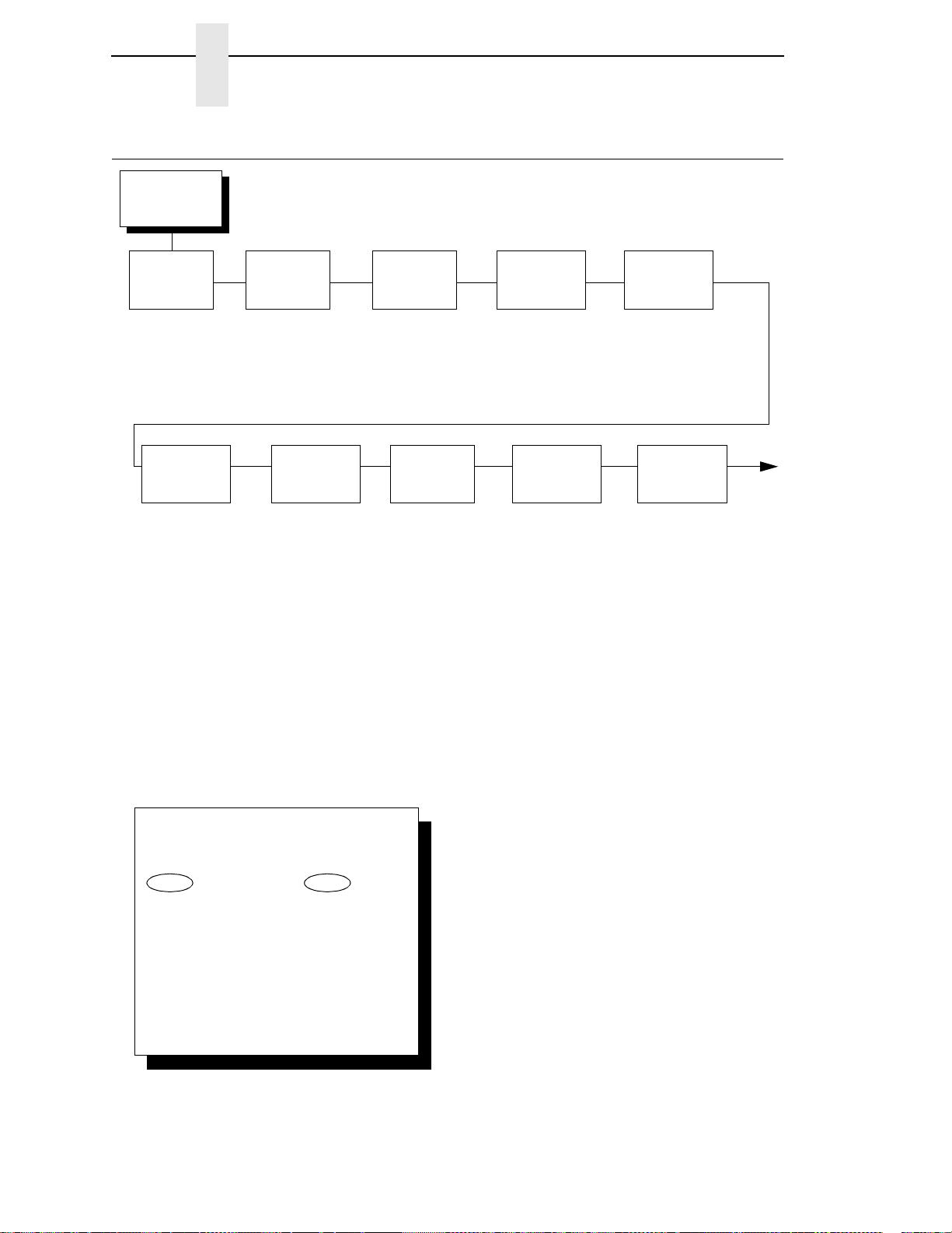
Quick Setup
(From page 52)
Interface
Selection
Auto Switching*
Parallel
Serial
Ethernet
1
Ethernet
Address
1
IP Address
2
Subnet Mask
2
Gateway Address
2
MAC Address
2
DHCP
2
Wireless
Address
1
IP Address
3
Subnet Mask
3
Gateway Address
3
MAC Address
3
DHCP
3
Print Quality
NOTE:
* = Factory Default
1
If installed.
2
If selected.
3
If wireless is selected.
4
Hanzi GB/Big5 build only
5
Hangul build only
6
Default for Hangul
7
Default for GB
8
Default for Big5
To cycle through the menus and its
options, press MENU then:
To enter a menu or select menu options,
press ENTER.
To return to a previous menu level,
press RETURN.
To exit the configuration menus
and return to READY, press START.
Scroll/
Micro
Scroll/
Micro
LQ*
6, 8
NLQ*
7
Normal
Hi-Speed
Super Hi-Speed
Ultra Hi-Speed
OR
Lines Per
Inch
6.0 Lines Per In*
8.0 Lines Per In
10.3 Lines Per In
3.0 Lines Per In
4.0 Lines Per In
Adapter
Address
1
DBCS CPI
6.0 CPI*
6
6.7 CPI *
7, 8
7.5 CPI
8.5 CPI
5
10.0 CPI
5
Other CPI
5.0 CPI
DBCS ASCII
Style
Normal*
Oversize
4
OCRB
DBCS To
ASCII
4
DBCS Mode*
ASCII Mode
Graphics Spd
Up
Normal*
Enhanced
Turbo
Match Typeface
IP Address
2
Subnet Mask
2
Gateway Address
2
MAC Address
2
DHCP
2
Chapter 4
Quick Setup Menu
Quick Setup Menu
54
Page 55
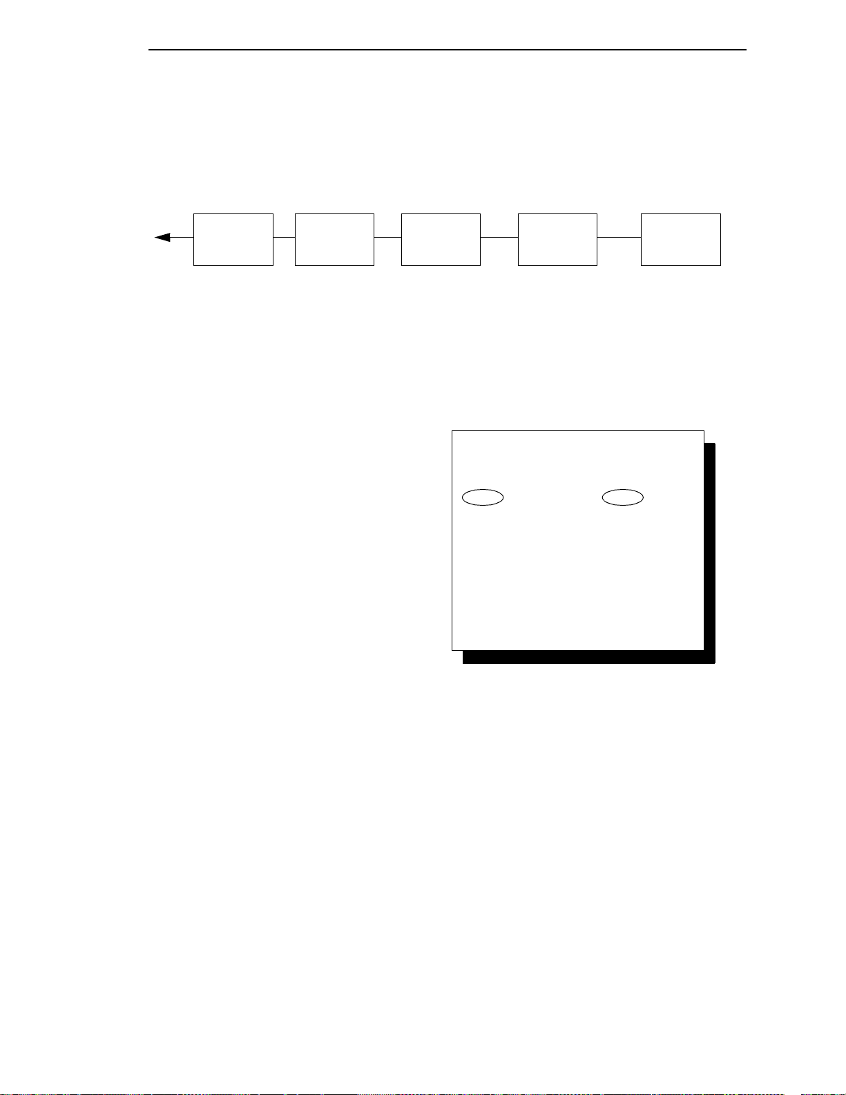
Save Current
Values
Change
Power On Set
Custom Set 1*
Custom Set 2
Custom Set 3
Custom Set 4
Custom/Preload Set 5
Custom/Preload Set 6
Custom/Preload Set 7
Custom/Preload Set 8
Factory Default
Custom Set 1*
Custom Set 2
Custom Set 3
Custom Set 4
Custom/Preload Set 5
Custom/Preload Set 6
Custom/Preload Set 7
Custom/Preload Set 8
Reset
Command
Load Factory*
Load Power On
Recall
Custom Set
Factory Default*
Custom Set 1
Custom Set 2
Custom Set 3
Custom Set 4
Custom/Preload Set 5
Custom/Preload Set 6
Custom/Preload Set 7
Custom/Preload Set 8
Lighter -10
Lighter -9
Lighter -8
Lighter -7*
Lighter -6
Lighter -5
Lighter -4
Lighter -3
Lighter -2
Lighter -1
Normal
Darker +1
Darker +2
Darker +3
Darker +4
Darker +5
Darker +6
Ribbon End
Point
To cycle through the menus and its
options, press MENU then:
To enter a menu or select menu options,
press ENTER.
To return to a previous menu level,
press RETURN.
To exit the configuration menus
and return to READY, press START.
Scroll/
Micro
Scroll/
Micro
OR
* = Factory Default
Quick Setup Menu
The purpose of the Quick Setup menu is to have the items that are most
frequently changed or entered during the installation of the printer in one
location. This is not a “quick access” menu, in that the items found here will
generally only be needed during the initial setup rather than on an ongoing
basis. Only those items where input is needed to enable printing from a host
system and establish rudimentary printing parameters are included. All other
menu selections not part of this section can be left in their default state to
achieve successful printing.
Most items displayed for selection in the Quick Setup menu dynamically
change depending on which Host Interface options are installed and selected
or which active emulation is selected. Only items that are routinely selected,
modified or confirmed during initial setup will be displayed (not full menus). In
most cases, the default settings provided throughout should be sufficient to
initiate successful printing and only need to be confirmed.
55
Page 56

Chapter 4
Quick Setup Menu
Changes made in the Quick Setup menu will have global impact. For
example, host interface settings made will carry forward and reflect in the
Host Interface menu as well. Similarly, changes made to any other parameter
will be universally applied (changing the default values) in all emulations or
locations where these settings are applicable.
An Active Emulation menu has been added. Depending on the emulations
installed or selected, a series of additional menus will appear dynamically,
depending on which emulation was chosen. The choice of emulations offered
depends on what emulations are included in the printer’s software and have
been enabled by the Security Key.
As the active emulation is selected from either the Quick Setup Menu or from
the original Active Emulation menu location, the corresponding bottom menus
for the remaining emulations will be hidden. Only the menu tree for the
selected active emulation will be displayed.
56
Page 57
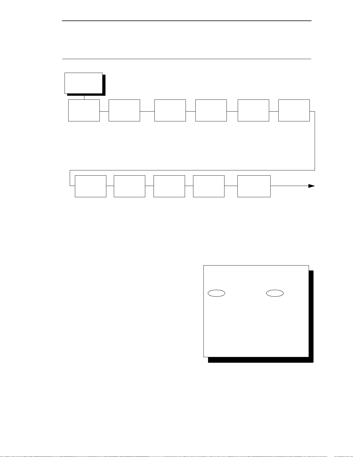
Printer
Control
(From page 52)
Interface
Selection
Autoswitching*
Parallel
Serial
Ethernet
2
Display
Language
English*
Print
Direction
Bidirectional*
Unidirectional
Hex Print
Mode
Disable*
Enable
Power On
State
Ready*
Not Ready
Paper Jam
Detection
Enable*
Disable
Form
Speeds
Normal Speed*
Slow Speed
Set Platen At
BOF
Disable*
Open
Shuttle
Timeout
5 Seconds*
1 - 60 Seconds
Energy
Saver Timer
15 Minutes*
1 - 60 Minutes
240 Minutes
Instant
5 - 30 Seconds
NOTE:
* = Factory Default
1
Top exit tear path can only be selected on pedestal
models.
2
Either the Network Setup menu or the Parallel Interface
menu will display. They cannot be displayed at the same
time.
(Continued on
next page)
Eject/Restore
Standard*
Top Exit Tear
1
To cycle through the menus and its
options, press MENU then:
To enter a menu or select menu options,
press ENTER.
To return to a previous menu level,
press RETURN.
To exit the configuration menus
and return to READY, press START.
Scroll/
Micro
Scroll/
Micro
OR
Printer Control Menu
Printer Control Menu
57
Page 58
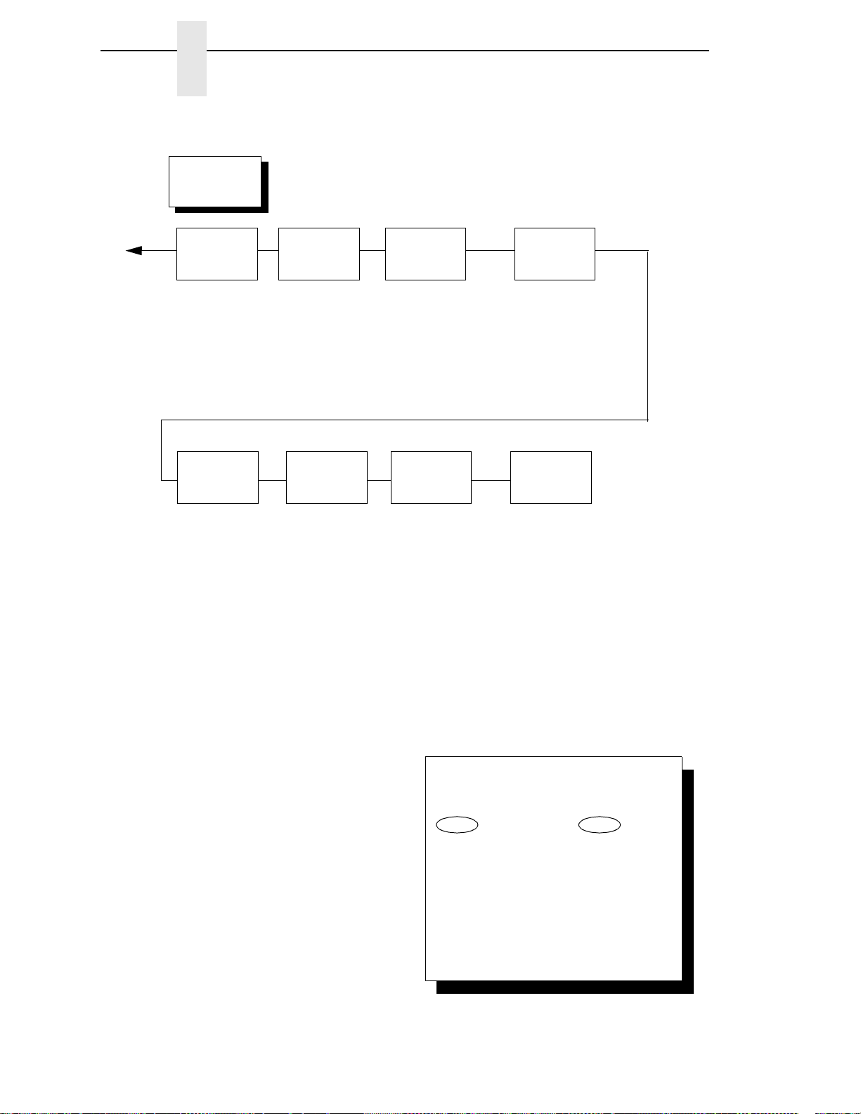
Chapter 4
PTR Setup
Option
Setup Parse
Disable*
Enable
Ignore
Setup SFCC
21h*
1 - FF
File
System
Overwrite Files
Enable*
Disable
View File List
Delete Files
Flash Avail.
Optimize&Reboot
Print File List
Printer
Control
(Continued)
Printer
Management
Port
Disable*
Serial
Debug Ethernet
Debug Adapter
Top Exit
Tear Distance
7.46 Inches*
4.50 - 10.50 Inches
Ribbon
Action
Stop Ribbon End*
Ignore Ribbon End
NOTE:
* = Factory Default
1
Top exit tear path can only be selected on
pedestal models.
2
Either the Network Setup menu or the Parallel
Interface menu will display. They cannot be
displayed at the same time.
3
Only available in Hanzi build.
Print DBCS
Font File Log
Lighter -10
Lighter -9
Lighter -8
Lighter -7*
Lighter -6
Lighter -5
Lighter -4
Lighter -3
Lighter -2
Lighter -1
Normal
Darker +1
Darker +2
Darker +3
Darker +4
Darker +5
Darker +6
Ribbon End
Point
DBCS Font
Download
3
Save To Flash
Delete DL Font
To cycle through the menus and its
options, press MENU then:
To enter a menu or select menu options,
press ENTER.
To return to a previous menu level,
press RETURN.
To exit the configuration menus
and return to READY, press START.
Scroll/
Micro
Scroll/
Micro
OR
Printer Control Menu
58
Page 59

Printer Control Menu
Interface Selection
Interface selection enables or disables physical interfaces for attachment
switching. If an interface is disabled, it is set offline and any data received will
be ignored.
When coax or twinax is selected, a POR status is sent to the host. Selecting
Autoswitching provides automatic interface switching among parallel, serial,
and either coax or twinax communication. Only one interface can be enabled
at a time. Configuration of the Auto Switching Hotport is done from the
corresponding interface menu, as shown in the following sections.
NOTE: When used with serial, parallel, and coax or twinax emulations,
Autoswitching does NOT save the state of each emulation during
interface switching. In this case, it is the responsibility of the host
application program to initialize the emulation to the desired state as
the beginning of each job. It is also the responsibility of the host
application program to correctly position the forms at “top of form” and
the end of each job.
Display Language
This parameter selects the language in which the operator panel messages
will display.
Print Direction
The PRINT DIRECTION feature affects both print quality and printing speed.
By setting this feature, you can configure the printer to print in both directions
of the shuttle sweep (Bidirectional), or to print in only one direction
(Unidirectional).
You might want to use Unidirectional when printing bar codes, high qualty text
and graphics, or other printing that requires precise vertical alignment.
Although enabling this feature reduces print speed, it enhances the vertical
alignment of dots and produces cleaner, sharper bar codes and text.
•
Bidirectional (the default). Prints all data in both directions of the shuttle
sweep. This choice produces higher printing speed.
•
Unidirectional. Prints all data in only one direction of the shuttle sweep.
This choice produces higher print quality.
59
Page 60

Chapter 4
Printer Control Menu
Hex Print Mode
A hex code printout (or hex dump) translates all incoming data to hexadecimal
equivalents. A hex dump lists each ASCII data character received from the
host computer, together with its corresponding two–digit hexadecimal code.
Hex dumps can be used to troubleshoot some types of printer data reception
problems.
•
Disable (the default)
•
Enable
Refer to page 134 to obtain a hex code printout.
NOTE: Printing in Hex Mode may alter print attributes set at the operator
panel or by the host computer. These attributes may need to be reset
after exiting Hex Print Mode.
Power On State
This parameter allows you to configure the printer to power on in the READY
or NOT READY mode.
ATTENTION
•
Ready (the default)
•
Not Ready
Paper Jam De tectio n
This parameter determines whether or not paper jam detection is active.
•
Enable (the default). Detects paper jams.
•
Disable. Disables paper jam checking to prevent false errors.
When paper jam detection is disabled, the printer does not monitor
paper motion. If a paper jam occurs, the printer ignores the condition
and continues to print, possibly causing severe damage to the printer.
Forms Speed
FORMS SPEED affects the speed at which paper moves into the stacking
area of the printer.
•
Normal Speed (the default). Will slew and stack paper, such as singlesheet data processing paper, at maximum speed.
•
Slow Speed. Will slew and stack at a slower pace. This ensures that
forms, such as multiple-sheet (i.e. invoice), will stack more neatly.
60
Page 61

Printer Control Menu
Set Platen At BOF
Some special forms have perforation areas that are thicker than the rest of the
form. Enable this parameter when you are using this type of form. This
parameter, when open is selected, allows the platen to open and close when
perforations thicker than the rest of a form move across the platen.
To retain print quality with this type of form, set the position of the first and last
print lines to avoid printing where paper thickness occurs (before and after the
perforation). See Forms Length on
•
Disable (the default)
•
Open
NOTE: When enabling this parameter, you must set the forms length to
match the physical distance between perforations.
page 103.
Shuttle Timeout
The SHUTTLE TIMEOUT parameter determines the amount of time the
shuttle will continue running after printing stops. This allows the shuttle to
continue moving during the time between print jobs when the print jobs arrive
at frequent intervals. Time is saved if the shuttle is still moving when a print
job arrives at the printer, since the printer does not have to wait for the shuttle
to reach its operating speed.
•
5 Seconds (the default)
•
1 – 60 Seconds
Energy Saver Timer
This parameter helps to reduce power consumption when the printer is not in
use in order to reduce air pollution caused by power generation. Use of this
feature can cut energy use by more than 50 percent.
ENERGY SAVER TIMER determines the amount of time that expires before
the printer reduces power after printing stops. The energy saver mode can
select an energy saver activation time from instant to 60 minutes. The
selections are:
•
15 Minutes (the default)
•
1 – 60 Minutes
•
240 Mins
•
Instant
•
5 – 30 Seconds.
NOTE: If the printer enters energy saver mode while NOT READY, the
printer will not print any jobs until made READY by pressing the
START key.
61
Page 62

Chapter 4
Printer Control Menu
Eject/Restore
The EJECT/RESTORE parameter controls how the printer behaves when the
user presses the EJECT/RESTORE key. The following options are available:
•
Standard (the default)
•
Top Exit Tear (pedestal models only)
When STANDARD mode is selected, the EJECT/RESTORE key operates as
follows:
•
Pressing EJECT/RESTORE causes the paper to advance a preset
distance of 22 inches.
•
Pressing READY or pressing EJECT/RESTORE a second time causes
the paper to return to its original position.
NOTE: If you are using this function to tear off forms, you might want to press
FORM FEED before using the EJECT/RESTORE function. This will
avoid unloading the paper as it is restored to its original position.
When TOP EXIT TEAR mode is selected, the EJECT/RESTORE key
operates as follows:
•
Pressing EJECT/RESTORE causes the paper to advance the bottom of
the last printed form to the tear position, ready for the operator to tear off
the printed forms.
•
Pressing EJECT/RESTORE a second time causes the paper to move into
position such that the top of the first possible form available for printing is
positioned ready for printing. (The direction and amount of paper
movement will depend on the length of the forms; one or more blank
forms will be skipped.)
NOTE: The TOP EXIT TEAR setting is meaningful only on pedestal model
printers. TOP EXIT TEAR cannot be selected on cabinet model
printers.
Forms length must be set correctly for the TOP EXIT TEAR mode to
function properly.
PTR Setup Option
This option selects the Special Function Control Code (SFCC) for the
PTR_SETUP command and functions. The selections for this process are
given below.
Setup Parse
This selection is used to enable or disable the PTR Setup Option.
62
•
Disable (the default)
•
Enable
•
Ignore
Page 63

Printer Control Menu
Setup SFCC
Sets the legal hex values from 01 through FF. These represent the ASCII
code (in hexadecimal) of the character used as the SFCC.
•
21h (the default). Corresponds to the “1” character.
•
1 – FF
File System
Provides the means for listing, viewing, and manipulating files in flash
memory. The following selections are available.
•
Overwrite. This selection controls whether the files in flash memory can
be overwritten. With the default selection of Enable, files are overwritten.
If the selection is disabled, the files can not be overwritten.
•
View Files. This selection provides a list of files in flash memory.
Pressing the SCROLL/MICRO key allows you to view the file size.
•
Delete Files. This selection provides a list of files in flash memory.
Pressing the ENTER key will delete the displayed file from flash memory.
•
Flash Avail. This selection provides a list of available files in flash
memory.
•
Optimize & Reboot. Pressing the ENTER key with this selection
displayed will reclaim flash memory space and reboot the printer.
IMPORTANT
Do not turn the printer off until it has completed the reboot and is either
Ready or Not Ready.
•
Print File List. Pressing the ENTER key with this selection displayed will
cause the printer to print a summary of files stored in flash memory.
Statistics on file system usage are also printed.
Printer Management Port
Printer Management Port is the port used to connect the printer to the
InfoPrint Printer Management Unit (PMU). This menu option is a printer
management tool that runs on Host Computers. The options include:
•
Disable (default)
•
Serial
•
Debug Ethernet
•
Debug Adapter
63
Page 64

Chapter 4
Printer Control Menu
Top Exit Tear Distance
The eject distance for the EJECT/RESTORE type TOP EXIT TEAR.
•
7.46 Inches (default)
•
4.50 - 10.50 Inches
Ribbon End Point
This parameter adjusts the point at which the system will declare the ribbon
as being expended. The life count will always be from 100% to 0%, but if a
darker setting is selected 0% will be reached more quickly. If a lighter setting
is selected, the system will extend the time it takes to reach 0%. The range of
values are as follows:
•
Lighter -1 through Lighter -10
•
Normal
•
Darker +1 through Darker +6
NOTE: This value can be adjusted at any time and the display will
automatically adjust to show the correct percentage relative to the
new end point.
Ribbon Action
•
Stop Ribbon End (the default). Stops ribbon action when ribbon life
reaches 0%.
•
Ignore Ribbon End. When selected, the ribbon life display remains on
the control panel, and the printer continues to monitor ink consumption.
DBCS Download
Allows you to save and delete downloadable DBCS characters from flash.
64
Page 65

Configuration Manageme nt Menu
The CONFIG. CONTROL menu allows you to control your printer’s
configurations according to the specifications necessary for your print jobs.
Configuration Management Menu
65
Page 66
Chapter 4
Configuration
Management
(from page 52)
Recall
Custom Set
FACTORY DEFAULT*
CUSTOM SET 1
CUSTOM SET 2
CUSTOM SET 3
CUSTOM SET 4
CUSTOM/PRELOAD SET 5
CUSTOM/PRELOAD SET 6
CUSTOM/PRELOAD SET 7
CUSTOM/PRELOAD SET 8
Save
Current Values
CUSTOM SET 1*
CUSTOM SET 2
CUSTOM SET 3
CUSTOM SET 4
CUSTOM/PRELOAD SET 5
CUSTOM/PRELOAD SET 6
CUSTOM/PRELOAD SET 7
CUSTOM/PRELOAD SET 8
Delete
Custom Set
Change
Power On Set
Protect
Custom Sets
Disable*
Enable
Print Custom
Set Values
CURRENT CUSTOM SET*
FACTORY DEFAULT
POWER ON CUSTOM SET
ALL CUSTOM SETS
CUSTOM SET 1
CUSTOM SET 2
CUSTOM SET 3
CUSTOM SET 4
CUSTOM/PRELOAD SET 5
CUSTOM/PRELOAD SET 6
CUSTOM/PRELOAD SET 7
CUSTOM/PRELOAD SET 8
CURRENT QUICK SETUP
Name Custom
Sets
CUSTOM SET 1
CUSTOM SET 2
CUSTOM SET 3
CUSTOM SET 4
CUSTOM/PRELOAD SET 5
CUSTOM/PRELOAD SET 6
CUSTOM/PRELOAD SET 7
CUSTOM/PRELOAD SET 8
Reset Custom
Set Names
CUSTOM SET 1*
CUSTOM SET 2
CUSTOM SET 3
CUSTOM SET 4
CUSTOM/PRELOAD SET 5
CUSTOM/PRELOAD SET 6
CUSTOM/PRELOAD SET 7
CUSTOM/PRELOAD SET 8
ALL CUSTOM SETS
CUSTOM SET 1*
CUSTOM SET 2
CUSTOM SET 3
CUSTOM SET 4
CUSTOM/PRELOAD SET 5
CUSTOM/PRELOAD SET 6
CUSTOM/PRELOAD SET 7
CUSTOM/PRELOAD SET 8
FACTORY DEFAULT*
CUSTOM SET 1
CUSTOM SET 2
CUSTOM SET 3
CUSTOM SET 4
CUSTOM/PRELOAD SET 5
CUSTOM/PRELOAD SET 6
CUSTOM/PRELOAD SET 7
CUSTOM/PRELOAD SET 8
Config Key
Default
QUICK SETUP CONFIG*
COMPLETE CONFIG
To cycle through the menus and its
options, press MENU then:
To enter a menu or select menu options,
press ENTER.
To return to a previous menu level,
press RETURN.
To exit the configuration menus
and return to READY, press START.
Scroll/
Micro
Scroll/
Micro
OR
* = Factory Default
Configuration Management Menu
66
Page 67

Configuration Management Menu
Recall Custom Set
The printer can store 8 custom sets in NVRAM. This parameter allows you to
select and load a specific custom set.
•
Factory Default (the default). The factory–preset custom set; its
parameters cannot be changed. It is always available for loading.
Custom/Preload Sets 5-8 contain configuration sets that assist with the
installation and configuration of this printer. These sets are preloaded at the
factory. If these sets are not used, you can delete them and create new
custom sets.
Save Current Values
This option allows you to save your custom sets to meet different print job
requirements. This eliminates the need to change the parameter settings for
each new job.
The custom sets are stored in NVRAM—they will not be lost if you power off
the printer.
Factory default is a factory–preset custom set; it cannot be changed or saved.
IMPORTANT
A new custom set will overwrite an existing custom set if the PROTECT
CUSTOM SETS parameter is disabled (e.g., a new Custom Set 4 will
overwrite an existing Custom Set 4). See the “Protect Custom Sets” in
this section.
Delete Custom Set
You can delete one or all of your customized or preloaded custom sets.
Factory default is a factory–preset custom set and cannot be changed or
deleted.
Change Power On Set
You can specify which of the custom sets will be the power-on custom set.
The printer will power on with the factory set values or with one of the
customized configurations.
67
Page 68

Chapter 4
Configuration Management Menu
Protect Custom Sets
The PROTECT CUSTOM SETS option specifies whether or not a new
custom set can overwrite an existing custom set when you activate the SAVE
CURRENT VALUES parameter.
•
Disable (the default). Turns protection off, allowing you to overwrite
existing custom sets.
•
Enable. Turns protection on, preventing you from overwriting existing
custom sets. If you attempt to save to an existing set, the following
operator panel message appears:
043 CUSTOM SET ALREADY EXISTS
DELETE FIRST
You must delete the existing set before trying to save the new custom set.
Print Custom Set Values
This option is used to print a listing of various stored printer custom sets. It is
recommended that you store the printout of the custom sets in a safe place for
quick referral.
Config Key Default
This option configures the config key to print either the Quick setup menu or
the full config.
•
Quick Setup Config (the default). Prints the Quick setup configuration.
•
Complete Config. Prints the full configuration.
Name Custom Sets
You may specify a 39-character name which can be used to refer to a custom
set. The name you enter for a custom set will be used in the Recall Custom
Set, Save Current Values, Delete Custom Set, Change Power On Set, Protect
Custom Sets, Print Custom Set Values, and Name Custom Sets menus. The
name can only be cleared by using the Reset Custom Set Names menu.
Press the SCROLL/MICRO or SCROLL/MICRO keys to cycle through
the values available for that character at the cursor location. Press the
SCROLL/MICRO key to move to the next character to be modified. Press
the SCROLL/MICRO key to go back to a character you have already
modified. Continue until you have entered the name you want to give to this
custom set, then press ENTER to save. The name you entered will now
represent this custom set on the printer's front panel. To exit this menu
without saving, press any key other than the ENTER key. The custom set
name will revert to the last saved value.
68
Reset Custom Set Names
You can reset specific custom set names back to the default value of the
configuration number.
Page 69
Ethernet Address Menu
Ethernet
Address
(from page 52)
IP ADDRESS
XXX.XXX.XXX.XXX
SUBNET
MASK
GATEWAY
ADDRESS
MAC
ADDRESS
hhhhhhhhhhhh
DHCP
Disable*
Enable
* = Factory Default
XXX.XXX.XXX.XXX
XXX.XXX.XXX.XXX
To cycle through the menus and its
options, press MENU then:
To enter a menu or select menu options,
press ENTER.
To return to a previous menu level,
press RETURN.
To exit the configuration menus
and return to READY, press START.
Scroll/
Micro
Scroll/
Micro
OR
Ethernet Parame te rs Me nu
IP ADDRESS
A numeric address such as 123.45.61.23 which identifies a printer or server in
a LAN or WAN.
SUBNET MASK
A binary value used to divide IP networks into smaller subnetworks or
subnets. This mask is used to help determine whether IP packets need to be
forwarded to other subnets.
GATEWAY ADDRESS
A gateway address is the IP address of a hardware device (gateway) that
translates data between two incompatible networks, which can include
protocol translation.
MAC ADDRESS
This menu item is the Manufacturer’s Assigned Number, and is unique for
each printer. It is read-only.
69
Page 70
Chapter 4
Ethernet
Parameters
(from page 52)
Buffer Size in
KBytes
Netbios
Protocol
ASCII Data
Port Number
Keep-Alive
Timer
* = Factory Default
Ethernet
Speed
Job Control Ethernet
Hotport
Enable*
Disable
9100*
1023 - 65535
3 Minutes*
2 - 10 Minutes
Auto Select*
10 Half Duplex
10 Full Duplex
100 Half Duplex
100 Full Duplex
Standard*
Enhanced
Off
64*
1-256
Timeout
10 Sec*
10 sec. - 60 sec.
To cycle through the menus and its
options, press MENU then:
To enter a menu or select menu options,
press ENTER.
To return to a previous menu level,
press RETURN.
To exit the configuration menus
and return to READY, press START.
Scroll/
Micro
Scroll/
Micro
OR
Ethernet Parameters Menu
DHCP
You can enable/disable the DHCP protocol using this option, but consult your
administrator for the appropriate setting. The options are:
•
Disable (the default)
•
Enable.
Ethernet Parameters Menu
70
Page 71

Ethernet Parame te rs Me nu
Buffer Size in KBytes
This option configures the amount of memory allocated for the Ethernet
buffer. You can specify between 1, 2, 4, 8, 16, 32, 128, and 256 Kbytes.
The default is 64 Kbytes.
Netbios Protocol
This option determines whether the NetBIOS protocol will be available. The
selections are as indicated below:
•
Enable (default). Makes the NetBIOS protocol available with the ethernet
installed.
•
Disable. Makes the NetBIOS protocol unavailable during printer
operation.
ASCII Data Port Number
This option sets the port number for ASCII print jobs. The data port number
needs to match your host system setting.
•
9100 (default)
•
1023 - 65535
Keep-Alive Timer
This is the time that the Keep Alive Timer will run. With the Keep Alive Timer
on, the tcp connection will stay connected even after the print job has
terminated.
•
3 Minutes (default)
•
2 - 10 Minutes
Ethernet Speed
This menu option only appears if a 10/100Base-T network interface card
(NIC) is installed. The Ethernet Speed menu allows compatibility with different
systems and networks. The factory default is Auto Select.
•
Auto Select. (default) This setting tells the 10/100Base-T NIC to perform
an auto detection scheme and configure itself to be 10 Half Duplex, 10
Full Duplex, 100 Half Duplex, or 100 Full Duplex.
•
10 Half Duplex. Tells the 10/100Base-T NIC to communicate at 10
Megabits per second using half duplex.
•
10 Full Duplex. Tells the 10/100Base-T NIC to communicate at 10
Megabits per second using full duplex.
•
100 Half Duplex. Tells the 10/100Base-T NIC to communicate at 100
Megabits per second using half duplex.
•
100 Full Duplex. Tells the 10/100Base-T NIC to communicate at 100
Megabits per second using full duplex.
71
Page 72

Chapter 4
Ethernet Parameters Menu
Job Control
The job control mode has three options:
•
Standard (default). The NIC waits for the printer to finish receiving the
current job before sending another job. The status line shows “done”
when the job is completely received by the NIC. This is the default.
•
Enhanced. The NIC waits for the printer to finish receiving the current job
before sending another job. The status line shows “done” when the job is
fully printed.
•
Off. No job synchonization between the NIC and the printer.
Ethernet Hotport
Gives the printer the ability to handle multiple data streams simultaneously. It
allows the printer to service hosts attached to the Serial and Ethernet ports as
if they were the only interface connected.
•
Timeout. This is the value used by the printer to time out from the current
port and check the other ports for data to print. When the printer has not
received data from the host after a certain period of time, it needs to
timeout to service the other ports.
•
10 Sec (the default)
•
10 sec - 60 sec.
72
Page 73
Adapter Address Menu
ADAPTER
ADDRESS
(from page 52)
IP Address Subnet
Mask
xxx.xxx.xxx.xxx xxx.xxx.xxx.xxx xxx.xxx.xxx.xxx hhhhhhhhhhhh
* = Factory Default
Gateway
Address
MAC
Address
DHCP
Disable*
Enable
To cycle through the menus and its
options, press MENU then:
To enter a menu or select menu options,
press ENTER.
To return to a previous menu level,
press RETURN.
To exit the configuration menus
and return to READY, press START.
Scroll/
Micro
Scroll/
Micro
OR
Adapter Parameters Menu
IP Address
A numeric address such as 123.45.61.23 which identifies a printer or server in
a LAN or WAN.
Subnet Mask
A binary value used to divide IP networks into smaller subnetworks or
subnets. This mask is used to help determine whether IP packets need to be
forwarded to other subnets.
Gateway Address
A gateway address is the IP address of a hardware device (gateway) that
translates data between two incompatible networks, which can include
protocol translation.
MAC Address
This menu item is the Manufacturer’s Assigned Number, and is unique for
each printer. It is read-only.
73
Page 74
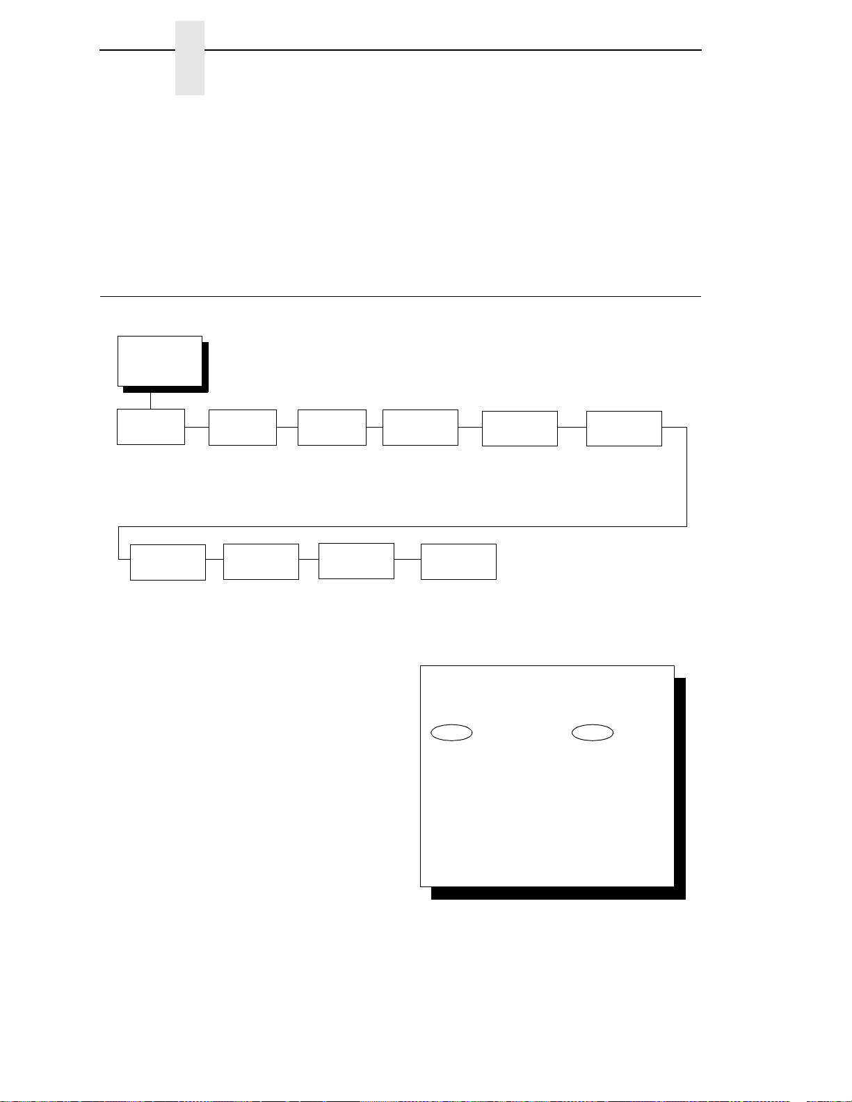
Chapter 4
ADAPTER
PARAMETERS
(from page 52)
Novell
Protocol
Enable*
Disable
Auto*
Bindery
NDS
* = Factory Default
Novell
Frame
Ethernet
Speed
Ethernet II
Ethernet 802.3
Ethernet 802.2*
802.2 Snap
Auto Select*
10 Half Duplex
10 Full Duplex
100 Half Duplex
100 Full Duplex
Nest Serv
Type
Keep Alive
Timer
3 Minutes*
2 - 10 Minutes
NetBIOS
Protocol
Enable*
Disable
Job Control
Standard
Enhanced*
Off
ASCII Data
Port Number
9100*
1023 - 65535
Buffer Size
in KBytes
64*
1 - 256
Ethernet
Hotport
Timeout
10 Sec*
10 Sec. - 60 Sec.
To cycle through the menus and its
options, press MENU then:
To enter a menu or select menu options,
press ENTER.
To return to a previous menu level,
press RETURN.
To exit the configuration menus
and return to READY, press START.
Scroll/
Micro
Scroll/
Micro
OR
Adapter Parameters Menu
DHCP
You can enable/disable the DHCP protocol using this option, but consult your
administrator for the appropriate setting.
The options include:
•
Disable (default)
•
Enable.
Adapter Parame ters Menu
You may enable or disable the Novell or NetBIOS Protocols within this menu,
as well as selecting which Novell Frame scheme to use in processing Novell
signals. See the Novell chapter in the InfoPrint 6500 Line Matrix Printers:
Ethernet Interface Card User's Manual for more details.
74
Page 75

Adapter Parameters Menu
Buffer Size in KB ytes
This option configures the amount of memory allocated for the Ethernet
buffer. You can specify between 1, 2, 4, 8, 16, 32, 128, and 256 Kbytes. The
default is 64 Kbytes.
Novell Protocol
This option determines whether the Novell protocol will be available. The
selections are as indicated below:
•
Enable (default). Makes the Novell protocol available with the ethernet
installed.
•
Disable. Makes the Novell protocol unavailable during printer operation.
Nest Serv Ty pe
You can change the Nest Server using this option, but consult your
administrator for the appropriate setting.
The options are Bindery (the factory default), NDS, and Auto.
NetBIOS Protocol
This option determines whether the NetBIOS protocol will be available. The
selections are as indicated below:
•
Enable (default). Makes the NetBIOS protocol available with the ethernet
installed.
•
Disable. Makes the NetBIOS protocol unavailable during printer
operation.
Novell Frame
This selection determines which framing scheme will be used in processing
Novell signals.
•
Ethernet II
•
Ethernet 802.3
•
Ethernet 802.2
•
802.2 Snap
ASCII Data Port Number
This option sets the port number for ASCII print jobs. The data port number
needs to match your host system setting.
•
9100 (default)
•
1023 - 65535
75
Page 76

Chapter 4
Adapter Parameters Menu
Keep Alive Timer
This is the time that the Keep Alive Timer will run. With the Keep Alive Timer
on, the tcp connection will stay connected even after the print job has
terminated.
•
3 Minutes (default)
•
2 - 10 Minutes
Ethernet Speed
This menu option only appears if a 10/100Base-T network interface card
(NIC) is installed. The Ethernet Speed menu allows compatibility with different
systems and networks. The factory default is Auto Select.
•
Auto Select. (default) This setting tells the 10/100Base-T NIC to perform
an auto detection scheme and configure itself to be 10 Half Duplex, 10
Full Duplex, 100 Half Duplex, or 100 Full Duplex.
•
10 Half Duplex. Tells the 10/100Base-T NIC to communicate at 10
Megabits per second using half duplex.
•
10 Full Duplex. Tells the 10/100Base-T NIC to communicate at 10
Megabits per second using full duplex.
•
100 Half Duplex. Tells the 10/100Base-T NIC to communicate at 100
Megabits per second using half duplex.
•
100 Full Duplex. Tells the 10/100Base-T NIC to communicate at 100
Megabits per second using full duplex.
Job Control
The job control mode has three options:
•
Standard (default). The NIC waits for the printer to finish receiving the
current job before sending another job. The status line shows “done”
when the job is completely received by the NIC. This is the default.
•
Enhanced. The NIC waits for the printer to finish receiving the current job
before sending another job. The status line shows “done” when the job is
fully printed.
•
Off. No job synchonization between the NIC and the printer.
Ethernet Hotport
Gives the printer the ability to handle multiple data streams simultaneously. It
allows the printer to service hosts attached to the Serial and Ethernet ports as
if they were the only interface connected.
76
•
Timeout. This is the value used by the printer to time out from the current
port and check the other ports for data to print. When the printer has not
received data from the host after a certain period of time, it needs to
timeout to service the other ports.
•
10 Sec (the default)
•
10 sec - 60 sec.
Page 77
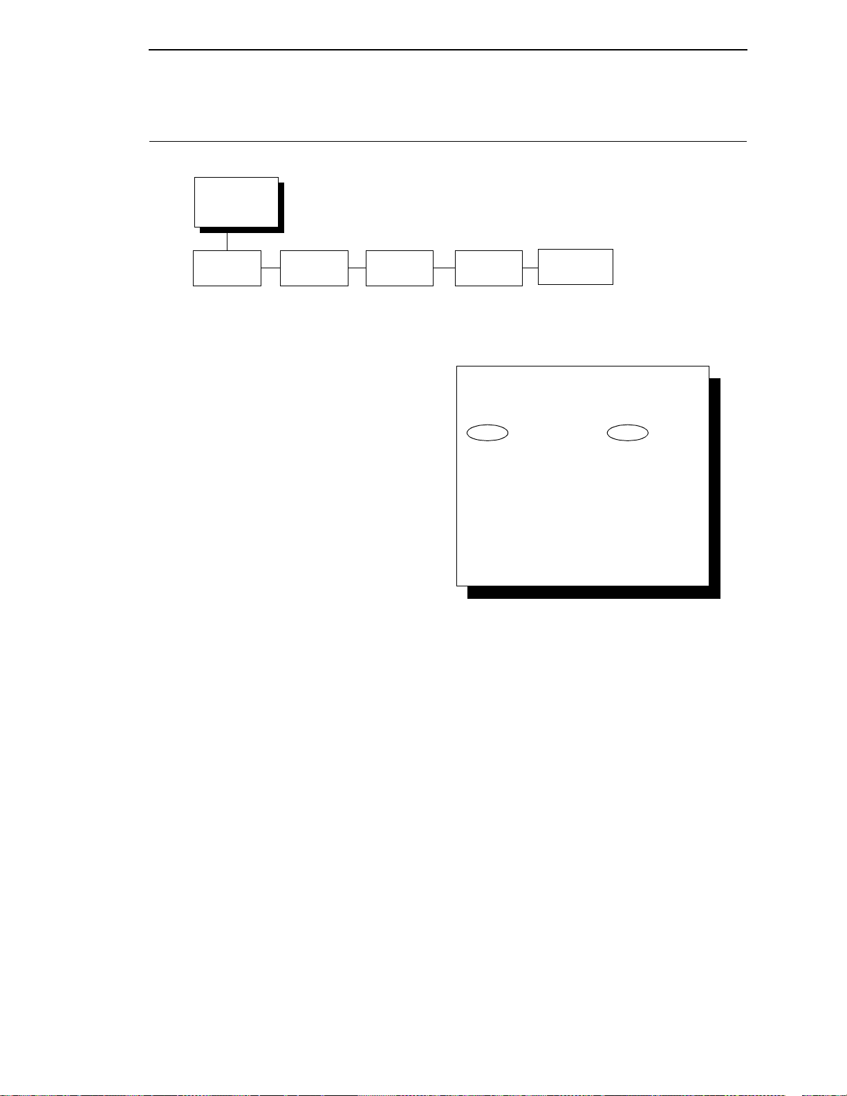
Wireless Add ress Menu
WIRELESS
ADDRESS
(from page 52)
IP Address Subnet
Mask
xxx.xxx.xxx.xxx xxx.xxx.xxx.xxx xxx.xxx.xxx.xxx hhhhhhhhhhhh
* = Factory Default
Gateway
Address
MAC
Address
DHCP
Disable*
Enable
To cycle through the menus and its
options, press MENU then:
To enter a menu or select menu options,
press ENTER.
To return to a previous menu level,
press RETURN.
To exit the configuration menus
and return to READY, press START.
Scroll/
Micro
Scroll/
Micro
OR
Wireless Parameters Menu
IP Address
A numeric address such as 123.45.61.23 which identifies a printer or server in
a LAN or WAN.
Subnet Mask
A binary value used to divide IP networks into smaller subnetworks or
subnets. This mask is used to help determine whether IP packets need to be
forwarded to other subnets.
Gateway Address
A gateway address is the IP address of a hardware device (gateway) that
translates data between two incompatible networks, which can include
protocol translation.
77
Page 78

Chapter 4
Wireless Address Menu
MAC Address
This menu item is the Manufacturer’s Assigned Number, and is unique for
each printer. It is read-only.
DHCP
You can enable/disable the DHCP protocol using this option, but consult your
administrator for the appropriate setting.
The options include:
•
Disable (default)
•
Enable.
78
Page 79
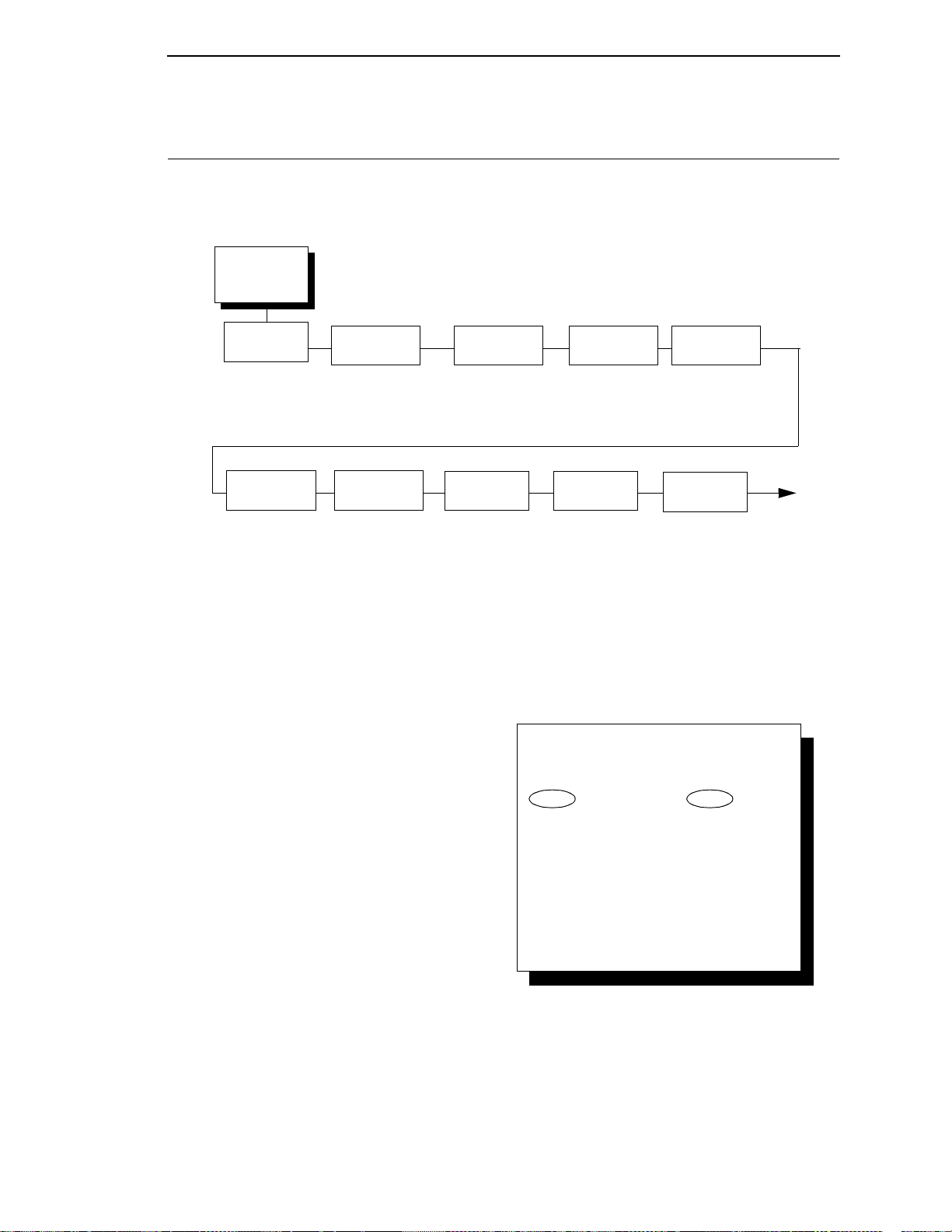
Wireless
Parameters
(from page 52)
Signal
Strength
0
SSID
Name
SSID Name (01 - 15) *
SSID Name (16 - 30)
SSID Name (31 - 32)
Preamble
Default*
Short
Long
Antenna
Diversity
Diverse*
Primary
Auxiliary
NOTE:
* = Factory Default
1 = Only when 40 Bites is selected
2 = Only when 128 Bits is selected
3 = Only when a Symbol radio card is installed.
4 = Only when a Cisco radio card is installed.
Minimum
Transfer Rate
Auto-negotiate*
1Mb/Sec
2Mb/Sec
5.5Mb/Sec
11Mb/Sec
Power
Management
0 ms.*
100 ms.
200 ms.
300 ms.
400 ms.
500 ms.
600 ms.
700 ms.
800 ms.
900 ms.
1000 ms.
Transmit
Power
100%*
0 - 100 %
Channel
Default*
1 - 15
Reset SSID
Name
Operation
Mode
Infrastructure*
Pseudo IBSS
Ad Hoc
To cycle through the menus and its
options, press MENU then:
To enter a menu or select menu options,
press ENTER.
To return to a previous menu level,
press RETURN.
To exit the configuration menus
and return to READY, press START.
Scroll/
Micro
Scroll/
Micro
OR
Wireless Parameters Menu
Wireless Parameter s Menu
79
Page 80
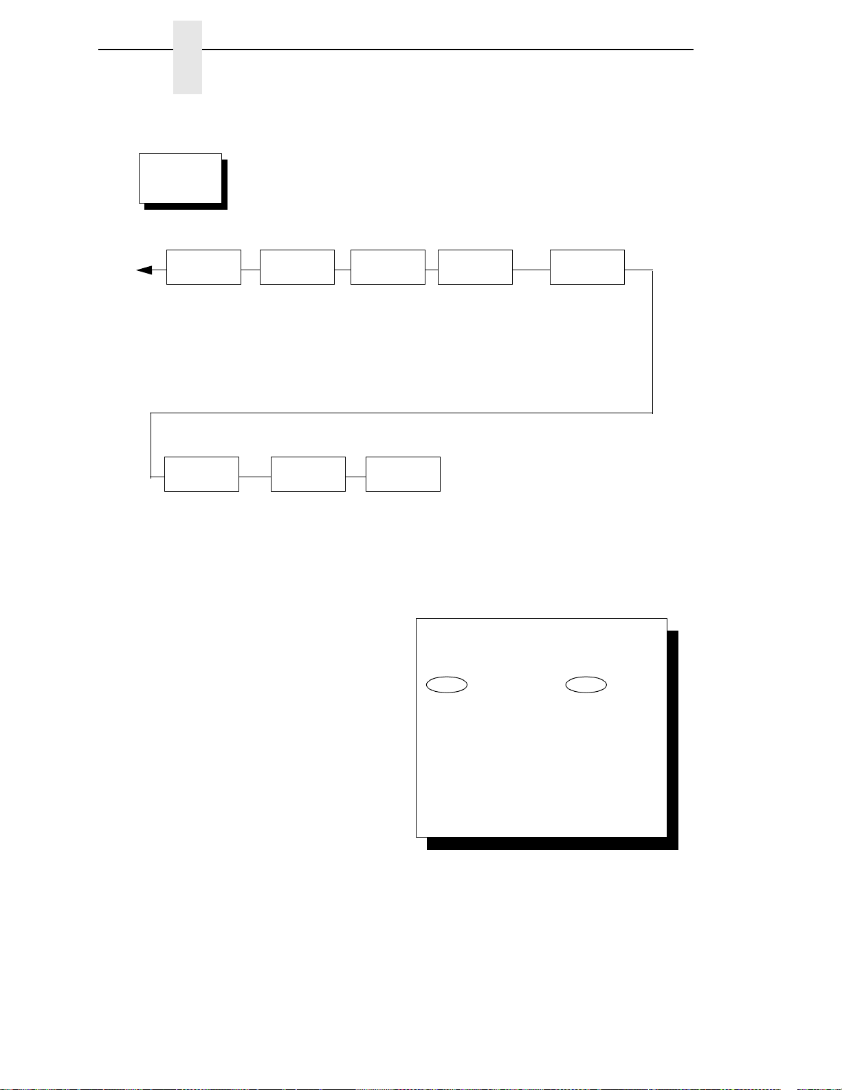
Chapter 4
Wireless
Parameters
(continued)
NOTE:
* = Factory Default
1 = Only when 40 Bites is selected
2 = Only when 128 Bits is selected
3 = Only when a Symbol radio card is installed.
4 = Only when a Cisco radio card is installed.
Default WEP
Key
0*
1
2
3
4
WEP Key 1
Key Format
Hexadecimal*
ASCII
Key Width
128 Bits*
40 Bits
Byte 1: - Bytes 5
1
Byte 1: - Bytes 13
2
WEP Key 2
Key Format
Hexadecimal*
ASCII
Key Width
128 Bits*
40 Bits
Byte 1: - Bytes 5
1
Byte 1: - Bytes 13
2
International
Mode
Disable*
Enable
Authentication
Mode
Open*
Shared
Kerberos
3
LEAP
4
WEP Key 3
Key Format
Hexadecimal*
ASCII
Key Width
128 Bits*
40 Bits
Byte 1: - Bytes 5
1
Byte 1: - Bytes 13
2
WEP Key 4
Key Format
Hexadecimal*
ASCII
Key Width
128 Bits*
40 Bits
Byte 1: - Bytes 5
1
Byte 1: - Bytes 13
2
Reset WEP
Keys
To cycle through the menus and its
options, press MENU then:
To enter a menu or select menu options,
press ENTER.
To return to a previous menu level,
press RETURN.
To exit the configuration menus
and return to READY, press START.
Scroll/
Micro
Scroll/
Micro
OR
Wireless Parameters Menu
80
Page 81

Wireless Parameters Menu
Signal Strength
This menu displays the strength of the wireless signal.
NOTE: This is a display value only and cannot be changed.
SSID Name
A 1 - 32 character, case sensitive string that identifies the group the printer
talks to.
NOTE: The SSID name may be edited in three parts (1 - 15), (16 - 30), and
(31 - 32).
For each part of the SSID name, press the LINE FEED or FORM FEED keys
to cycle through the values available for that character at the cursor location.
Press the SCROLL/MICRO key to move to the next character to be
modified. Press the SCROLL/MICRO key to go back to a character you
have already modified. Continue until you have entered the name you want to
give to this SSID name, then press ENTER to save. The name you entered
will now represent this SSID name on the printer’s front panel. To exit this
menu without saving, press any key other than the ENTER key. The SSID
name will revert to the last saved value.
Reset SSID Name
Allows you to reset the SSID name.
Operation Mode
Allows you to select the way the Wireless option communicates:
•
Infrastructure (default). The Wireless option must go through a server.
•
Pseudo IBSS. Proprietary, peer-to-peer communication (without a
server). The two peers can be from different manufacturers.
•
Ad Hoc. Standard, peer-to-peer communication (without a server). The
two peers can be from different manufacturers.
Minimum Transfer Rate
Allows you to set the minimum speed at which the Wireless Option will accept
a connection (in million bits per second). The options are:
•
Auto-negotiate (default)
•
1Mb/Sec.
•
2Mb/Sec.
•
5.5Mb/Sec
•
11Mb/Sec
Channel
Allows you to select the RF channel. The options are Default (the factory
default) and 1-15.
81
Page 82

Chapter 4
Wireless Parameters Menu
Antenna Diversity
The type of antenna used:
•
Diverse (default). Select when you want to use the antenna with the best
reception.
•
Primary. Select when you want to use the Primary antenna on the server.
•
Auxiliary. Select when you want to use the Auxiliary antenna on the
server.
Preamble
The length of the preamble in transmit packets.
•
Default. The Wireless option automatically determines the length.
•
Short. For newer printers which can handle higher transer rate speeds.
•
Long. For older printers which cannot handle higher transfer rate speeds.
Power Management
This allows you to set power-save mode and sleep time. A value specifying
the sleep time in milliseconds will be provided. If set to zero, power-save
mode will be disabled. The range includes:
•
0 ms. (default)
•
100 ms. - 1000 ms.
Transmit Power
The power level as a percentage of full power (0 - 100%).
International Mode
When enabled, the Wireless option adapts to international frequency
requirements in Europe. The options include:
•
Disable (default)
•
Enable
Authentication Method
This feature allows the user to select the authentication method used for the
wireless network interface.
•
Open (the default). Selects open authentication.
•
Shared. Selects shared key authentication.
•
Kerberos. Selects Kerberos authentication (for use when a Symbol RF
card is installed).
•
LEAP. Selects LEAP authentication (for use with a Cisco RF card
installed).
82
Page 83

Parallel Interface Menu
Default WEP Key
This feature enables you to encrypt (scramble) information for security
purposes. With this feature, you can set up to four encryption keys, in either
ASCII or hexadecimal format, and in either 40 or 128 bits. (The more bits you
choose, the more difficult it will be to decode the information.)
NOTE: None of the WEP Key Configuration menus display on the
configuration printout.
WEP Key Format
Allows you to format the WEP keys in ASCII or hexadecimal code. The default
is hexadecimal.
WEP Key Width
This is the encryption strength. The options are 40 Bits and 128 Bits; 40 Bits
are weaker and 128 Bits are stronger.
NOTE: If you select 40 Bits, the WEP key BYTE6 throught WEP Key
BYTE13 menus will not display.
The default is 128 Bits.
WEP Key BYTE1 through BYTE 13
These are the individual characters of the encryption key.
Reset WEP Keys
Allows you to reset all four WEP keys (WEP Key 1 through WEP Key 4) at
one time.
83
Page 84
Chapter 4
Parallel
Interface
(from page 52)
Interface
Type
IEEE 1284*
PC Parallel
Dataproducts
PC Parallel
See page 86
Parallel
Hotport
Trickle Time
1/4 Sec*
1/2 Sec
1 Sec
2 Sec
4 Sec
8 Sec
16 Sec
OFF
Timeout
10 Sec.*
1 Sec. - 60 Sec.
Report Status
Disable*
Enable
IEEE 1284
See page 89
* = Factory Default
To cycle through the menus and its
options, press MENU then:
To enter a menu or select menu options,
press ENTER.
To return to a previous menu level,
press RETURN.
To exit the configuration menus
and return to READY, press START.
Scroll/
Micro
Scroll/
Micro
OR
Parallel Interface Menu
Parallel Interface Menu
Refer to Chapter 5 for more information about printer interfaces.
Interface Type
The INTERFACE TYPE parameter selects which electrical interface will drive
the parallel port interface, as follows:
•
IEEE 1284 (the default)
•
PC Parallel
PC Parallel
See page 86.
IEEE 1284
See page 89.
84
Page 85

PC Parallel Menu
Parallel Hotport
Gives the printer the ability to handle multiple data streams simultaneously.
It allows the printer to service hosts attached to the serial and parallel ports as
if they were the only interface connected.
Trickle Time
This functionality prevents an attached host from timing out. In order to
support this feature, the port has to be able to accept data from the host and
store it for future use. The selected value is the time that the printer waits
before getting the next byte of data from the host. Set the value to be less
than the host time out value. If the value is too much shorter, the printer fills
up its buffer too fast.
•
1/4 Sec (the default)
•
1/2 Sec
•
1 Sec
•
2 Sec
•
4 Sec
•
8 Sec
•
16 Sec
•
OFF
Timeout
This is the value used by the printer to time out from the current port and
check the other ports for data to print. When the printer has not received data
from the host after a certain period of time, it needs to Timeout in order to
service the other ports.
•
10 Sec. (the default)
•
10 Sec. - 60 Sec.
Report Status
When this option is enabled, faults are reported even if the fault is not on the
current active port. If the option is disabled, a fault on the printer is reported
only if it occurs on the active port.
•
Disable (the default)
•
Enable
85
Page 86
Chapter 4
PC Parallel
(from page 84)
Data Bit 8
Enable*
Disable
Data
Polarity
Standard*
Inverted
Strobe
Polarity
Standard*
Inverted
Response
Polarity
Standard*
Inverted
Latch
Data On
Leading Edge*
Trailing Edge
Busy On
Strobe
Enable*
Disable
Prime
Signal
Disable*
Enable
TOF Act at
Prime Signal
Form Feed at Reset*
No Form Feed at Reset
Buffer Size in
Kbytes
64*
1 - 256
* = Factory Default
Auto
Trickle
Disable*
Enable
Trickle
Time
1/4 sec*
1/2 sec
1 sec
2 sec
4 sec
8 sec
16 sec
OFF
To cycle through the menus and its
options, press MENU then:
To enter a menu or select menu options,
press ENTER.
To return to a previous menu level,
press RETURN.
To exit the configuration menus
and return to READY, press START.
Scroll/
Micro
Scroll/
Micro
OR
Parallel Interface Menu
PC Parallel Menu
The PC PARALLEL menu configures the electrical signals to operate as a
PC Parallel printer.
86
Data Bit 8
The DATA BIT 8 parameter allows access to the extended ASCII character
set. When this parameter is disabled, the printer interprets bit 8 of each
incoming data character as a zero, regardless of its actual setting.
The extended ASCII character set is shown in the InfoPrint 6500 Line Matrix
Printers: ASCII Programmer’s Reference Manual.
•
Enable (the default)
•
Disable.
Page 87

PC Parallel Menu
Data Polarity
The DATA POLARITY parameter must be set to match the data polarity of
your host computer.
•
Standard (the default). Does not expect the host computer to invert the
data.
•
Inverted. Expects the host computer to invert the data received on the
data lines. Ones become zeros, and vice–versa.
Strobe Polarity
The STROBE POLARITY must be set to match the data strobe polarity of
your host computer. When the host computer sends a data strobe signal to
the printer, this enables the printer to read the data bus.
•
Standard (the default). Does not expect the data strobe signal to be
inverted.
•
Inverted. Expects the host computer to invert the data strobe signal.
Response Polarity
The RESPONSE POLARITY parameter must be set to match the response
polarity of your host computer.
•
Standard (the default). Does not invert the response signal.
•
Inverted. Inverts the response signal sent to the host computer.
Busy on Strobe
BUSY ON STROBE determines when the Busy signal is asserted.
•
Enable (the default). Asserts a busy signal after each character is
received.
•
Disable. Asserts a busy signal only when the print buffers are full.
Latch Data On
The LATCH DATA ON parameter specifies whether the data is read on the
leading or trailing edge of the data strobe signal.
•
Leading Edge (the default)
•
Trailing Edge
Prime Signal
•
Enable (the default). When set and the host asserts the PRIME SIGNAL,
the parallel port will perform a warm start.
•
Disable. The parallel port will not perform a warm start when the host
asserts the PRIME SIGNAL.
87
Page 88

Chapter 4
Parallel Interface Menu
TOF Act at Prime Signal
TOF (Top–of–Form) ACTION AT PRIME SIGNAL determines whether or not
a form feed is performed before a warm start when the prime signal is
asserted from the host. This setting is only used if PRIME SIGNAL parameter
is enabled.
•
Form Feed At Reset (the default)
•
No Form Feed At Reset.
Buffer Size in Kbytes
This parameter determines the size of the input buffer.
•
64K (the default)
•
1 – 256K
Auto Trickle
Auto Trickle is used to prevent a host computer from timing out because the
parallel interface was busy for too long. When Auto Trickle is enabled and the
printer's buffers are almost full, the printer will begin to trickle data in (at the
rate set in the Trickle Time menu) until the buffers start to empty out.
Trickle Time
This functionality prevents an attached host from timing out. To support this
feature, the port has to be able to accept data from the host and store it for
future use. The selected value is the time that the printer waits before getting
the next byte of data from the host. Set the value to be less than the host time
out value. If the value is too much shorter, the printer fills up its buffer too fast.
•
1/4 Sec (the default)
•
1/2 Sec
•
1 Sec
•
2 Sec
•
4 Sec
•
8 Sec
•
16 Sec
•
OFF
88
Page 89
IEEE 1284
(from page 84)
Buffer Size in
Kbytes
Auto
Trickle
Disable*
Enable
Trickle
Time
1/4 sec*
1/2 sec
1 sec
2 sec
4 sec
8 sec
16 sec
OFF
* = Factory Default
64*
(1-256)
To cycle through the menus and its
options, press MENU then:
To enter a menu or select menu options,
press ENTER.
To return to a previous menu level,
press RETURN.
To exit the configuration menus
and return to READY, press START.
Scroll/
Micro
Scroll/
Micro
OR
Serial Interface Menu
IEEE 1284 Menu
IEEE 1284 Menu
The IEEE 1284 interface is configured using the following configuration
options.
Buffer Size in Kbytes
This parameter determines the size of the input buffer. Up to 256K are
available.
•
64 (the default)
•
1 – 256
Auto Trickle
Auto Trickle is used to prevent a host computer from timing out because the
parallel interface was busy for too long. When Auto Trickle is enabled and the
printer's buffers are almost full, the printer will begin to trickle data in (at the
rate set in the Trickle Time menu) until the buffers start to empty out.
89
Page 90

Chapter 4
Parallel Interface Menu
Trickle Time
This functionality prevents an attached host from timing out. To support this
feature, the port has to be able to accept data from the host and store it for
future use. The selected value is the time that the printer waits before getting
the next byte of data from the host. Set the value to be less than the host time
out value. If the value is too much shorter, the printer fills up its buffer too fast.
•
1/4 Sec (the default)
•
1/2 Sec
•
1 Sec
•
2 Sec
•
4 Sec
•
8 Sec
•
16 Sec
•
OFF
90
Page 91
Serial Interface Menu
Serial
Interface
(from page 52)
Interface
Type
RS 232*
RS 422
Data
Protocol
XON/XOFF*
ETX/ACK
ACK/NAK
DTR
Baud
Rate
9600* Baud
19200 Baud
38400 Baud
57600 Baud
115200 Baud
600 Baud
1200 Baud
2400 Baud
4800 Baud
Data Bits
8*
7
Parity
None*
Odd
Even
Mark
Sense
Stop Bits
1*
2
Data Terminal
Ready
Ready/Buffer Not
Full*
Not Ready/
Buffer Full
False
True
Request To
Send
True*
Ready/Buffer
Not Full
Not Ready/
Buffer Full
False
Buffer Size in
Kbytes
64*
1 - 256
Poll
Character
00 Hex*
00 - FF Hex
One Char
Enquiry
Disable*
Enable
Serial
Hotport
Trickle Time
1/4 Sec*
1/2 Sec
1 Sec
2 Sec
4 Sec
8 Sec
16 Sec
OFF
Timeout
10 Sec.*
1 Sec. - 60 Sec.
Report Status
Disable*
Enable
Framing
Errors
Enable*
Disable
To cycle through the menus and its
options, press MENU then:
To enter a menu or select menu options,
press ENTER.
To return to a previous menu level,
press RETURN.
To exit the configuration menus
and return to READY, press START.
Scroll/
Micro
Scroll/
Micro
OR
* = Factory Default
The serial parameters in the printer must be set to match the serial
interface in the host computer (at the other end of the printer data
cable). Otherwise, the printer may not operate correctly, and data
characters from the computer may not print or may appear as “garbled”
text.
IMPORTANT
Serial Interface Menu
IEEE 1284 Menu
91
Page 92

Chapter 4
Serial Interface Menu
Interface Type
This parameter configures the electrical interface for the serial port, as
follows:
•
RS-232 (the default)
•
RS-422
Data Protocol
You may select one of the following serial interface protocols to meet the host
interface requirements.
•
XON / XOFF (the default). Transmit On / Transmit Off. The printer
controls the flow of communication from the host by telling the host to turn
the transmission on and off. This is the factory default serial protocol.
•
ETX / ACK. End of Text / Acknowledge. The host controls the flow of
communication to the printer by sending a block of data and ending the
block with an End of Text (ETX) signal. When the printer receives the
ETX signal, it will acknowledge it has received the entire block of data.
•
ACK / NAK. Acknowledge / Negative Acknowledge. ACK means
acknowledge; the device acknowledges it has accepted a transmission.
NAK means a negative acknowledge; the device did not receive the
transmission.
•
DTR (DTE Ready). The printer controls the data flow by asserting or deasserting this hardware signal to the host. If there is enough room in the
printer buffer, the printer will send a high signal; if the buffer is full the
printer will send a low signal. DTR tells the host if it is safe to send more
data. (If the host sends data during an unsafe condition, data will be lost.)
Baud Rate
This parameter sets the baud rate of the serial interface in the printer. Baud
rate is the speed at which serial data is transferred between the host
computer and the printer.
•
9600 Baud (the default)
•
19200 Baud
•
38400 Baud
•
57600 Baud
•
115200 Baud
•
600 Baud
92
•
1200 Baud
•
2400 Baud
•
4800 Baud
Page 93

Serial Interface Menu
IEEE 1284 Menu
Data Bits
The DATA BITS parameter sets the length of the serial data word. The length
of the data word must match the corresponding data bits setting in the host
computer.
•
8 (the default)
•
7
Stop Bits
The STOP BITS parameter sets the number of stop bits in the serial data
word. The setting must match the corresponding stop bit setting in the host
computer.
•
1 (the default)
•
2
Parity
The PARITY parameter setting can be set for the following:
•
None (the default)
•
Odd
•
Even
•
Mark
•
Sense
The setting must match the corresponding parity setting in the host computer.
Data Terminal Ready
This configuration is part of hardware flow control and determines when the
DATA TERMINAL READY (DTR) signal is generated. This signal indicates
whether or not the printer is ready to receive data.
•
Ready/Bu ffer Not Full (the default). Asserts the DTR signal when the
printer is READY and the internal serial buffer is not full.
•
Not Ready/Buffer Full. Asserts the DTR signal when the printer is NOT
READY or the internal serial buffer is full.
•
False. Never asserts the DTR signal.
•
True. Continuously asserts the DTR signal.
NOTE: When the printer is attached to an AS/400, the DTR should be set to
TRUE.
93
Page 94

Chapter 4
Serial Interface Menu
Request to Send
This configuration is part of hardware flow control and determines when the
REQUEST TO SEND (RTS) signal is generated. This signal indicates
whether or not the printer is ready to receive data.
•
True (the default). Continuously asserts the RTS signal.
•
Ready/Bu ffer Not Full. Asserts the RTS signal when the printer is
READY and the internal serial buffer is not full.
•
Not Ready/ Buffer Full. Asserts the RTS signal when the printer is NOT
READY or the internal serial buffer is full.
•
False. Never asserts the RTS signal.
NOTE: Xon/Xoff is always on. See page 92 for more information.
Buffer Size in Kbytes
This parameter determines the size of the input buffer. Up to 256K are
available.
•
64 (the default)
•
1 – 256
Poll Character
This option is used when One Char Enquiry is enabled and the IGP feature is
available. Whenever the printer receives this character, it sends a response to
the host indicating the current state of the printer. It may be configured from
00 through FF Hex.
•
00 Hex (the default)
•
00 – FF Hex
One Char Enquiry
When enabled, and the IGP feature is available, a status byte is sent back to
the host when the poll character or the command SFCC enquiry is sent to the
printer (serial interface only). The poll character is received and the status
byte is sent whether the printer is online or offline. The SFCC enquiry will only
be processed when the printer is online.
•
Disable (the default)
•
Enable
94
Page 95

Emulation Configuration Menu
The status byte sent to the host is defined as follows:
BIT Use
7.6 0
5 1
4 0
3 1 = printer fault
2 1 = IGP busy
1 0 = offline, 1 = online
0 1 = serial input buffer exceeds xoff/on
IEEE 1284 Menu
Serial Hotport
Gives the printer the ability to handle multiple data streams simultaneously. It
allows the printer to service hosts attached to the serial and parallel ports as if
they were the only interface connected.
Trickle Time
This functionality prevents an attached host from timing out. To support this
feature, the port has to be able to accept data from the host and store it for
future use. The selected value is the time that the printer waits before getting
the next byte of data from the host. Set the value to be less than the host time
out value. If the value is too much shorter, the printer fills up its buffer too fast.
•
1/4 Sec (the default)
•
1/2 Sec
•
1 Sec
•
2 Sec
•
4 Sec
•
8 Sec
•
16 Sec
•
OFF
95
Page 96

Chapter 4
Serial Interface Menu
Timeout
This is the value used by the printer to time out from the current port and
check the other ports for data to print. When the printer has not received data
from the host after a certain period of time, it needs to Timeout in order to
service the other ports.
•
10 Sec. (the default)
•
1 Sec. – 60 Sec.
Report Status
When this option is enabled, faults are reported even if the fault is not on the
current active port. If the option is disabled, a fault on the printer is reported
only if it occurs on the active port.
•
Disable (the default)
•
Enable
Framing Errors
These are possible errors that can occur when serial interface settings of the
printer do not match those of the host computer.
•
Enable (the default). If a framing error occurs, a fault message will display
on the control panel.
•
Disable. If a framing error occurs, a fault message will not display on the
control panel.
96
Page 97
Emulation Configuration Menu
Emulation
Configuration
(from page 52)
ASCII Printer
Emulation
KS*
1
KSSM
1
LQ1600K
2
Print
Format
See page 99
Printer Emul
Config
See page 98
NOTE:
* = Factory Default
1
Hangul emulation only.
2
Hanzi emulation only.
To cycle through the menus and its
options, press MENU then:
To enter a menu or select menu options,
press ENTER.
To return to a previous menu level,
press RETURN.
To exit the configuration menus
and return to READY, press START.
Scroll/
Micro
Scroll/
Micro
OR
IEEE 1284 Menu
ASCII Printer Emulation
This parameter selects one of the following ASCII printer emulations as the
active emulation:
•
KS* (default for Hangul)
•
KSSM
•
LQ1600K (default for Hanzi)
Printer Emulation Configuration
This parameter configures the ASCII printer emulation and page formatting.
page 98.
The submenus are described on
Print Format
This parameter configures page formatting. The submenus are described
beginning on page
99.
97
Page 98
Chapter 4
Printer Emulation
Configuration
(from page 97)
KS
1
KSSM
1
LQ1600K
2
Printer
Emulation
Configuration
NOTE:
1
Hangul emulation only.
2
Hanzi emulation only.
To cycle through the menus and its
options, press MENU then:
To enter a menu or select menu options,
press ENTER.
To return to a previous menu level,
press RETURN.
To exit the configuration menus
and return to READY, press START.
Scroll/
Micro
Scroll/
Micro
OR
Emulation Configuration Menu
Printer Emul Config Menu
98
Page 99
Print
Format
(from page 97)
Characters
Per Inch
10.0 Characters Per In
12.0 Characters Per In*
13.3 Characters Per In
15.0 Characters Per In
16.7 Characters Per In
17.1 Characters Per In
20.0 Characters Per In
Lines
Per Inch
6.0 Lines Per Inch*
8.0 Lines Per Inch
10.3 Lines Per Inch
3.0 Lines Per Inch
4.0 Lines Per Inch
Forms
Width
Forms Width in Inches
13.6 Inches*
00.1 - 13.6 Inches
Forms Width in MM
345.4 MM*
.1 - 345.4 MM
Forms Width in Characters
132 Characters*
1 - 272 Characters
Forms
Length
Forms Length in Inches
11.0 Inches*
00.1 - 24 Inches
Forms Length in MM
279.4 MM*
000.1 - 609.6 MM
Forms Length in Lines
66 Lines*
1 - 192 Characters
DBCS CPI
5.0
6.0
4
6.7
5
7.5
8.5
1
10
1
other CPI
Styling Type
Myungjo*
1
Gothic
1
Ming*
2
Song*
3
Encoding
Address Table*
UTF-8
Address Table
Select
KSC5601*
1
G818030*
3
BIG5
2
CNS
2
TCA
2
ETEN
2
IBM5550
2
Teletext
2
Wang
2
Big5+
2
Big5E
2
HKSCS
2
Print
Quality
LQ *
6
NLQ*
7
Normal
Hi-Speed
Super Hi-Speed
Ultra Hi-Speed
NOTE:
* = Factory Default
1
Hangul only
2
Hanzi Big5 only
3
Hanzi GB only
4
Default for Hangul
5
Default for GB and Big5
6
Default for Hangul and Big5
7
Default for GB
To cycle through the menus and its
options, press MENU then:
To enter a menu or select menu options,
press ENTER.
To return to a previous menu level,
press RETURN.
To exit the configuration menus
and return to READY, press START.
Scroll/
Micro
Scroll/
Micro
OR
Print Format Menu
Print Format Menu
99
Page 100
Chapter 4
Reset
Command
Load Factory*
Load Power On
Perforation
Skip
1
Disable*
1/2 Inch
2/3 Inch
5/6 Inch
1 inch
Host
Command
Enable*
Ignore all
Ignore CPI
Ignore LPI
Ignore Unidirectional
Ignore Page Format
1
Error
Handling
Illegal Code Point
Taller 15 CPI
Disable*
Enable
Horizontal
Expnd
24* Pt Size
.
.
.
72 Pt Size
Vertical
Expnd
24* Pt Size
.
.
.
72 Pt Size
High Density
Disable*
Enable
Graphics
Spd Up
Normal*
Enhanced
Turbo
Match Typeface
Print Character
Table
Print
Attributes
Proportional Spacing
Disable*
Enable
Italic Print
Disable*
Forward Slant
Backward Slant
Slashed Zero
Disable*
Enable
DBCS To ASCII
DBCS Mode
ASCII Mode
DBCS ASCII Style
Normal
Oversize
2, 3
OCRB
Compress Mode
Disable*
Enable
DBCS Compressed
Disable*
Enable
Margins
Left Margin
0 Characters*
1 - 369 Characters
Right Margin
0 Characters*
1 - 369 Characters
Bottom Margin
0 Lines*
1 - 451 Lines
NOTE:
* = Factory Default
1
Hangul only
2
Hanzi Big5 only
3
Hanzi GB only
To cycle through the menus and its
options, press MENU then:
To enter a menu or select menu options,
press ENTER.
To return to a previous menu level,
press RETURN.
To exit the configuration menus
and return to READY, press START.
Scroll/
Micro
Scroll/
Micro
OR
Emulation Configuration Menu
100
 Loading...