

Page 1

Delta Elec. Inc. IN5316HD_IN5318 Rev .00
Company Confidential Infocus___________________ Delta________________
1
2011/10/11
DATA PROJECTOR
IN5316HD (LX786-69A)
IN5318 (LX766-69A)
SERVICE MANUAL
Page 2

Delta Elec. Inc. IN5316HD_IN5318 Rev .00
Company Confidential Infocus___________________ Delta________________
2
2011/10/11
CONTENTS
1.COMPLIANCE OF SAFE REPAIR..........................................................................................4
1-1.Caution During Disassembling And Assembling...............................................................4
1-2.Lamp................................................................................................................................ 4
1-3.Lens..................................................................................................................................4
1-4.Eye Safety Warnings........................................................................................................5
2.SPECIFICATIONS...................................................................................................................6
2-1.Summary Specifications.................................................................................................. 6
2-2.Front - right View…..……………………………………………..……………………..……....8
2-3.Top view…………..............................................................…………...………………......10
2-4.Rear view...........................................……………...........................................................11
2-5.Remote Control Parts….………………………...………………………………..…....….. ..13
2-6.Bottom View………………………………………………………………………..…………..18
2-7.
Adjusting Projected Image Position
Using Shift……..……………..……………………....19
2-8.Projection Distance and Size......................................................................................... 20
2-9.BLOCK DIAGRAM......................................................................................................... 23
3.TROUBLE SHOOTING......................................................................................................... 27
4. DISASSEMBLY AND ASSEMBL Y…………......................................................................... 34
5. Flash Upgrade Flow............................................................................................................. 60
6.Calibration……………………………..……………………………………..…….………………..68
7. Full set Adjust Procedure…………………………………………………………….……………72
8.Installing or Removing the Optional Lens………………..…………………………….…….……….73
9.Projection Lamp………………………….……………………………… …… …… …… … ..…… .. 75
10.Cleaning………………………………….………………………………………………………...78
11.SERVICE NOTE................................................................................................................. 79
11-1.Service Note Description............................................................................................. 79
11-2.Power & READY LED Blink Code Message.................................................................80
11-3.
Timing Mode Table.......................................................................................................81
12. RS-232 Command…………………………………………………………………..…………....84
13. EDID…………. .................................................................................................................101
14. RJ45………………………………………………………………………………………………118
15. Fan Control Checking Table………………………………………………………..………….127
16. Projector Dimension……………………………………………………… ………...…………..128
17. Projector Installation Notice……………………………………………………..……………..129
Page 3

Delta Elec. Inc. IN5316HD_IN5318 Rev .00
Company Confidential Infocus___________________ Delta________________
3
2011/10/11
18. Spare Part List .................................................................................................................130
Revision Description Date
Ver.00 Draft 10/11/2011
Ver.01 Preliminary 10/14/2011
Page 4

Delta Elec. Inc. IN5316HD_IN5318 Rev .00
Company Confidential Infocus___________________ Delta________________
4
2011/10/11
1. COMPLIANCE OF SAFE REPAIR
Be sure to read this Service Manual before providing services. In the projector, full
consideration is taken to ensure safety for fire, electric shock, injury, harmful radiation, and
substance. Therefore, observe the notice described in this Service Manual so that safety is
kept when providing services. Moreover, be sure to observe the notice described in the
Instruction Manual.
Pay attention to the following items during service inspection.
1-1 Cautions during disassembling and assembling
1. This equipment contains parts under high voltage. When making repairs, etc.
Be sure to pull out the power plug beforehand to insure safety.
2. Parts may be very hot immediately after use.
Make sure the equipment has cooled off sufficiently before carrying out repairs.
3. Make sure that parts and screws and wiring, etc. are returned to their original positions.
Tube, tape and other insulation materials have been used for safety reasons.
The internal wiring has been designed to avoid direct contact with hot parts or parts under
high voltage when using clamps or other tools.
4. The parts used in this device have special safety features such as flame-resistance and
anti-voltage properties. When replacing parts, always use parts supplied from the factory.
5. After finishing operations make sure that all parts and wires have been returned to their
original position and that there has been no deterioration of the area around the location that
was worked on.
6. Be sure to use a grounding strap (wrist band) during repair and inspection.
1-2 Lamp
During current conduction, the lamp is in the high-temperature state. In this case, pay
careful attention because a high voltage is used. When replacing a lamp, replace it after
confirming that the lamp has gotten cold sufficiently.
1-3 Lens
Do not look into a lens during projection. This damages your eyes.
Page 5

Delta Elec. Inc. IN5316HD_IN5318 Rev .00
Company Confidential Infocus___________________ Delta________________
5
2011/10/11
1-4 Eye Safety Warnings
1. Avoid staring directly into the projector’s beam of light at all times.
2. Minimize standing facing into the beam.
Keep your back to the beam as much as possible.
3. Ensure that projectors are located out of the line of sight from the screen to the audience;
this ensures that, when presenters look at the audience,
they do not also have to stare at the projector lamp.
5. When projector is used in a classroom, adequately supervise students when
they are asked to point out something on the screen.
6. In order to minimize the lamp power needed,
use room blinds to reduce ambient light levels.
Page 6
Delta Elec. Inc. IN5316HD_IN5318 Rev .00
Company Confidential Infocus___________________ Delta________________
6
2011/10/11
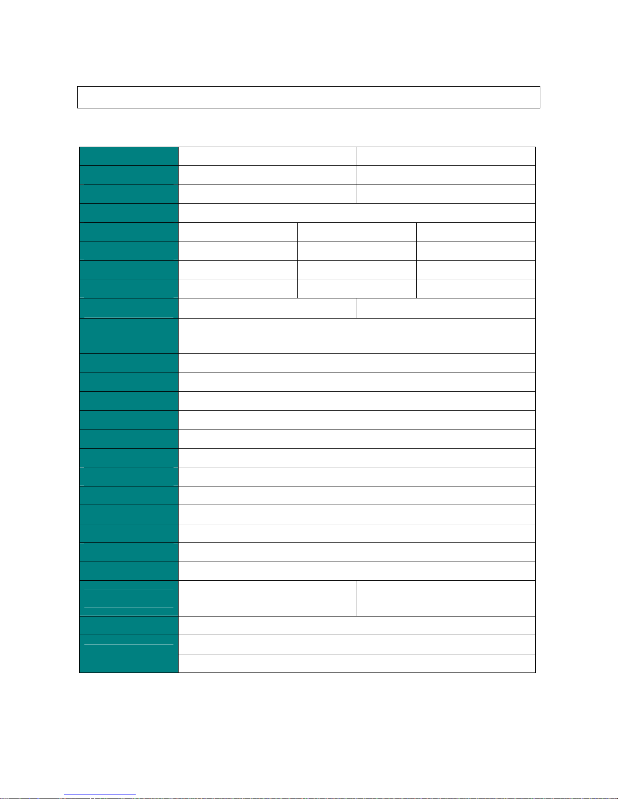
2. SPECIFICATIONS
2-1. Summary Specifications
Model
IN5316HD IN5318
Display type
TI DMD 1080P 0.65” TI DMD WUXGA 0.67”
Resolution
1920 x 1080 Native 1920 x 1200 Native
Weight
11.3 KG (typical)
Lens type
Standard Long Short
Projection distance
1.5 meters ~ 7 meters 2 meters ~ 20 meters 0.5 meters ~ 3 meters
Projection lens
Manual Focus/Manual Zoom Manual Focus/Manual Zoom Fix Zoom
Digital Zoom
1.25 1.5 Fix
Aspect Ratio
16:9 16:10
Vertical keystone
correction
+/- 15 degrees
Projection methods
Desktop (Rear, Front) /Ceiling (Rear, Front)
Data compatibility
VGA, SVGA, XGA, SXGA, SVGA+, UXGA, Mac
SDTV/EDTV/ HDTV
480i/576i, 480p/576p, 720p, 1080i, 1080p,WUXGA
Video compatibility
NTSC, PAL, SECAM
H-Sync
15, 31 – 90 KHz
V-Sync
23 - 85 Hz
Operation temperature
5° ~ 40°C
Dimensions / Weight
430.16 mm (W) x 175.00 mm (H) x 338.00 mm (D)
AC Input
AC Universal 110 ~ 240 ±10%, Typical @110 V
Power consumption
Normal mode: 350W / Bright mode: 410w
Stand By
< 1W @ 110Vac 60Hz
Lamp
OSRAM 330W (E20.9)
Brightness
3700lm(Avg.) , 3200lm(Min) / Bright
3100lm(Avg.) , 2600lm(Min) / Normal
3900lm(Avg.) , 3400lm(Min) / Bright
3200lm(Avg.) , 2800lm(Min) / Normal
Audio Speaker
3W speaker x 2
VGA x 2
Input Terminals
DISPLAYPORT x 1
Page 7

Delta Elec. Inc. IN5316HD_IN5318 Rev .00
Company Confidential Infocus___________________ Delta________________
7
2011/10/11
S-Video x 1
5 BNC (RGBHV) x 1
Component x 1
Composite video x 1
HDMI x 1
RCA stereo R/L x 2
Input Terminals
Mini-jack stereo x 1
VGA x 1
Output Terminals
Mini-jack stereo x 1
RS232C
RJ45
Screen trigger: DC jack x 1 (DC12V 200mA output function)
Control Terminals
USB
Security
Kensington Lock
Page 8

Delta Elec. Inc. IN5316HD_IN5318 Rev .00
Company Confidential InFocus___________________ Delta________________
8
2011/10/11
2-2. Front - right View
ITEM LABEL DESCRIPTION
1.
IR receiver Receiver IR signal from remote control
2.
Lens Projection Lens
3.
Focus ring Focuses the projector image
4.
Zoom ring Enlarges the projected image
5.
Height adjuster Adjusts level of projector
6.
Function keys See T op view-on screen Display (OSD) buttons and LEDS
7.
Lamp Cover Removes cover to replace lamp or color wheel
Page 9

Delta Elec. Inc. IN5316HD_IN5318 Rev .00
Company Confidential InFocus___________________ Delta________________
9
2011/10/11
8.
Vertical lens shift Adjusts the image position vertically
9.
Horizontal lens shift Adjusts the image position horizontally
10.
Lens release button Press the release button before removing the lens
Important:
Ventilation openings on the projector allow for good air circulation, which keeps the projector
lamp cool. Do not obstruct any of the ventilation openings.
Page 10

Delta Elec. Inc. IN5316HD_IN5318 Rev .00
Company Confidential InFocus___________________ Delta________________
10
2011/10/11
2-3. Top view
ITEM LABEL DESCRIPTION
1.
MENU Opens and exits OSD menus
2.
Left cursor Navigates and changes setting in the OSD / Quick Menu – For Volume
3.
UP cursor Navigate the OSD / Quick Menu – for keystone
4.
DOWN cursor Navigate the OSD / Quick Menu – for keystone
5.
Right cursor Navigates and changes setting in the OSD / Quick Menu – For Volume
6.
Select Enter or confirm highlighted OSD menu item
Page 11

Delta Elec. Inc. IN5316HD_IN5318 Rev .00
Company Confidential InFocus___________________ Delta________________
11
2011/10/11
2-4. Rear view
ITEM LABEL DESCRIPTION
1.
DC 12V TRIGGER Connect a 12V screen trigger (200ma max)
2.
AUDIO OUT Connect an AUDIO CABLE to an extemal speaker system
3.
AUDIO 3 (L and R) Connect the AUDIO CABLE from an input device
4.
VIDEO Connect the COMPOSITE CABLE from a video device
5.
S-VIDEO Connect the S-VIDEO CABLE from a video device
6.
YPbPr Connect the COMPONENT CABLE from a component video enabled device
7.
BNC Connect the BNC CABLES from a computer or a video enabled device
8.
AC IN Connect the POWER CABLE
9.
POWER SWITCH Connects AC power to the projector
10.
Safety Cable Anchor Secure a ceiling mount safety cable to this anchor
Page 12

Delta Elec. Inc. IN5316HD_IN5318 Rev .00
Company Confidential InFocus___________________ Delta________________
12
2011/10/11
11.
Security Lock Connect a security lock system to the projector and attach to a permanent oblect
12.
AUDIO 2 (L and R) Connect the AUDIO CABLES from an input device
13.
SERIAL Connect an RS-232 serial port cable for command control
14.
IR receive Receives the remote control IR signal
15.
AUDIO 1 Connect the AUDIO CABLE from an input device
16.
VGA OUT Connect the RGB CABLE to a display (Pass through by VGA1 only)
17.
USB Con nect the USB CABLE from a computer
18.
DISPLAYPORT Connect a DISPLAYPORT CABLE to a DISPLAYPORT source
19.
HDMI Connect the HDMI CABLE from an HDMI device
20.
VGA2 Connect the RGB CABLE from a computer or a video enable device
21.
RJ45 Connect a LAN CABLE for networking purposes
Red Normal operation
22.
READY LED
Flashing Red
Lamp is not ready (warming up / shutting down /
cooling)
23.
TEMP LED Red Overheating
Red Standby
Green Normal operation
24.
PWR LED
Flashing Red or Green Powering on / cooling
25.
Power Button Turns the projector on or off (main power switch must be turned on first)
26.
VGA1 Connect the RGB CABLE from a computer or a video enabled device
Page 13

Delta Elec. Inc. IN5316HD_IN5318 Rev .00
Company Confidential InFocus___________________ Delta________________
13
2011/10/11
2-5. Remote Control Parts
Page 14

Delta Elec. Inc. IN5316HD_IN5318 Rev .00
Company Confidential InFocus___________________ Delta________________
14
2011/10/11
ITEM LABEL DESCRIPTION
1.
Power on Turn the projector on
2.
LED indicator Only lights when the remote keys are pressed
3.
Display Mode Choose a suitable preset mode for usage environment
4.
Contrast
Display the Contrast setting bar and use the right and left keys to
adjust
5.
Brightness
Display the Brightness setting bar and use the right and lest keys to
adjust
6.
Left cursor
When the OSD is displayed, this button navigates to the left. When
USB has been connected to the projector and PC, the previous
presentation slide is displayed
7.
Menu Display the Menu OSD
8.
Auto image Re-synchronize the pc image
9.
Overscan Adjust overscan
10.
Source-1
VGA
11.
Source-4 S-VIDEO
12.
Source-7 NA
13.
Power OFF
Turn the projector off
14.
SOURCE
Display the source menu
15.
INFO
Display the projector information
16.
MUTE
Mute the audio
17.
UP CURSOR/
KEYSTONE+
When the OSD is displayed, this button navigates upthe menu.
Otherwise it adjusts the keystone
18.
SELECT
Enter and confirm setting in the OSD
Page 15

Delta Elec. Inc. IN5316HD_IN5318 Rev .00
Company Confidential InFocus___________________ Delta________________
15
2011/10/11
ITEM LABEL DESCRIPTION
19.
RIGHT CURSOR
When the OSD is displayed, this button navigates to the right. When
USB has been connected to the projector and PC, the previous
presentation slide is displayed
20.
DOWN CURSOR/
KEYSTONE-
When the OSD is displayed, this button navigates down the menu.
Otherwise it adjusts the keystone
21.
RESIZE Change the image aspect ratio
22.
BLANK
Blank the screen
23.
VOLUME+
Increase the volume
24.
FREEZE
Freeze video
25.
VOLUME-
Decrease the volume
26.
SOURCE-3
HDMI-2
27.
SOURCE-2
HDMI-1
28.
SOURCE-6
NA
29.
SOURCE-5
Turn the remote control backlight on or off
30.
LIGHT
Opens and exits the OSD
31.
SOURCE-8 NA
Page 16

Delta Elec. Inc. IN5316HD_IN5318 Rev .00
Company Confidential InFocus___________________ Delta________________
16
2011/10/11
Important:
1. Avoid using the projector with bright fluorescent lighting turned on. Certain high-frequency
fluorescent lights can disrupt remote control operation.
2. Be sure nothing obstructs the path between the remote control and the projector. If the path
between the remote control and the projector is obstructed, you can bounce the signal off
certain reflective surfaces such as projector screens.
3. The buttons and keys on the projector have the same functions as the corresponding
buttons on the remote control. This user’s manual describes the functions based on the remote
control.
Remote Control Operating Range
The remote control uses infrared transmission to control the projector. It is not necessary to
point the remote directly at the projector. Provided you are not holding the remote
perpendicular to the sides or the rear of the projector, the remote will function well within a
radius of about 7 meters (23 feet) and 15 degrees above or below the projector level.
Page 17

Delta Elec. Inc. IN5316HD_IN5318 Rev .00
Company Confidential InFocus___________________ Delta________________
17
2011/10/11
Inserting the remote control Batteries
1.
Remove the battery compartment
cover by sliding the cover in the
direction of the arrow.
2.
Insert the battery with the positive
side facing up.
3.
Replace the cover.
Caution:
1. Only use AA batteries (Alkaline batteries are recommended).
2. Dispose of used batteries according to local ordinance regulations.
3. Remove the batteries when not using the projector for prolonged periods.
Page 18

Delta Elec. Inc. IN5316HD_IN5318 Rev .00
Company Confidential InFocus___________________ Delta________________
18
2011/10/11
2-6. Bottom View
ITEM LABEL DESCRIPTION SEE PAGE:
1.
Leveling/Elevator Feet Raise an rotate the feet to change and fine tune the angle of the projector
2.
Ceiling support holes Only use with an InFocus ceiling mount system
Note:
When installing, ensure that you use only UL Listed ceiling mounts.
For ceiling installations, use approved mounting hardware and M4 screws with a maximum screw
depth of 6 mm (0.23 inch).
The construction of the ceiling mount must be of a suitable shape and strength. The ceiling mount
load capacity must exceed the weight of the installed equipment, and as an additional precaution be
capable of withstanding three times the weight of the equipment over a period of 60 seconds.
Page 19

Delta Elec. Inc. IN5316HD_IN5318 Rev .00
Company Confidential InFocus___________________ Delta________________
19
2011/10/11
2-7.
Adjusting Projected Image Position
Using Shift
The Shift feature provides a lens shift function that can be used to adjust the position of the
projected image either horizontally or vertically within the range detailed below.
Shift is a unique system that provides lens shift while maintaining a much higher ANSI contrast
ratio than traditional lens shift systems.
Page 20

Delta Elec. Inc. IN5316HD_IN5318 Rev .00
Company Confidential InFocus___________________ Delta________________
20
2011/10/11
2-8. Projection distance and size
For IN5316HD
Standard Projection lens: TR: 1.54~1.93; offset=100%
Long throw Projection lens: TR: 1.93~2.9; offset=100%
Page 21

Delta Elec. Inc. IN5316HD_IN5318 Rev .00
Company Confidential InFocus___________________ Delta________________
21
2011/10/11
Short throw Projection lens: TR: 0.77; offset=100%
For IN5318
Standard Projection lens: TR: 1.54~1.93; offset=5%
Long throw Projection lens: TR: 1.93~2.9; offset=5%
Page 22

Delta Elec. Inc. IN5316HD_IN5318 Rev .00
Company Confidential InFocus___________________ Delta________________
22
2011/10/11
Short throw Projection lens: TR: 0.77; offset=5%
Page 23

Delta Elec. Inc. IN5316HD_IN5318 Rev .00
Company Confidential InFocus___________________ Delta________________
23
2011/10/11
2-9. Block Diagram (Main Block)
0.7 WUXGA
0.65 1080P
Page 24

Delta Elec. Inc. IN5316HD_IN5318 Rev .00
Company Confidential InFocus___________________ Delta________________
24
2011/10/11
Explanation of the block diagrams
Input signal processing
RGB(1,2) & Component & VIDEO and S-VIDEO .
The RGB(D-sub15x2 or 5BNC) and COMPONENT input signals are switching output to
ADC front end(AFE1000) by EL4342. After these signals and VIDEO, S-VIDEO have been
converted into 10-bit digital signals of RGB/YUV each at the A/D converter (U507) , the
resultant signals are output to the scaler (U700).
Digital input system
DISPLAYPORT and HDMI
The DISPLAYPORT and HDMI signals input to HDMI receiver (U507). The signals are
further converted into 10-bit digital signals of RGB/YCbCr, and then output to the scaler
(U700).
Output signals processing
RGB out(D-sub15 black) .
The RGB output signals pass through fromVGA1 only by analog switching Ics (EL4342
and ADG659).
DDP2431 Image processing
− Auto-lock for Std, wide & black border
− Integrated 3D Video Decoder
− DynamicBlack™
− BrilliantColor™
− Dynamic & Anamorphic Scaling w/ Zoom
− 1D Keystone Correction
− Frame Rate Conversion
− Color Coordinate Adjustment
− White Color Temperature Adjustment
− Programmable Color Space Conversion
− Programmable Degamma & Splash
Page 25

Delta Elec. Inc. IN5316HD_IN5318 Rev .00
Company Confidential InFocus___________________ Delta________________
25
2011/10/11
− Spatial-Temporal Multiplexing
Digital video signal processing
*Scaler (U700)
• The RGB/YCbCr signals are processed for picture quality improvement and matrix
processing at the Scaler circuit.
• The output signals are switched over at the bus line after adjusting color space
processing, auto-adjustment, Degamma etc, these signals are written in the DDRII
DRAM(U707).
• The image signals called up from the DDRII DRAM, pass through the definition
converter circuit, ON-screen display, error diffusion circuit for DLP, and output to the
optical engine unit (DLP DMD board).
Timing signal processing
Scaler operates on an external single 32MHz crystal.
Audio signal processing
• The pre-amplifier (U21) is generated signals with volume control to audio
amplifier(U22) to driver speakers.
System control
The scaler(U700) controls all of this system.
− Built-in Lamp Ballast Control
− DMD Power and Reset Driver Control
− DMD horizontal and vertical Image Flip
Power circuit
* Main power supply
• In the state of standby, the power is supplied 3.3V to the MCU(U300).
• After power ON, the 1.2V,1.8V, 2.5V, 3.3V, 5Vand 12V are provided to the analog circuit,
fan, IO board, etc.
* Lamp power supply
• The lamp is lit with POWER ON.
Page 26

Delta Elec. Inc. IN5316HD_IN5318 Rev .00
Company Confidential InFocus___________________ Delta________________
26
2011/10/11
• Un-lighting detection is performed.
Safety design
• Fan circuit detection
• Lamp cover detection
• Lamp house temperature detection
• Thermal protector for the lamp power supply
• Lamp replacing time
Page 27
Delta Elec. Inc. IN5316HD_IN5318 Rev .00
Company Confidential InFocus___________________ Delta________________
27
2011/10/11
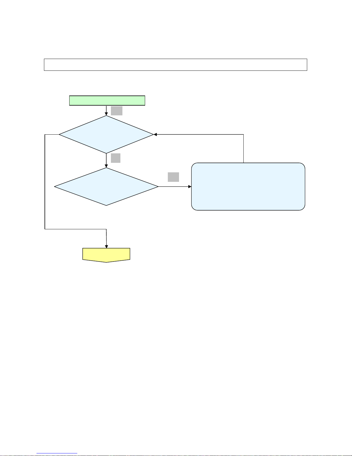
3. TROUBLE SHOOTING
By checking operations during normal usage time, it is possible to carry out judgments on malfunction
to a certain extent. Carry out the following checks before disassembling the equipment.
Waiting Power On
Connect the power cord
• Power Supply Unit malfunction
• Check Power BD CN201 to Format P4 connection
• Check Format P1 to MB CN550 connection
• Check MB CN111 to IO BD P8 connection
• Check MCU firmware is ok or not .
< Stand-by >
Power: Light (RED)
Ready :OFF
Tem
p
: OFF
< Power supply Error>
Power: OFF
Ready: OFF
Tem
p
: OFF
Yes
No
Yes
Page 28

Delta Elec. Inc. IN5316HD_IN5318 Rev .00
Company Confidential InFocus___________________ Delta________________
28
2011/10/11
Turn the power ON
Image
Display
<Normal operation Check >
Power: Light Green
Read
y
: Light Red
< Color Wheel >
Power: Green Flashing 9
<Lamp Error>
Power: Flashing Green x 5
• Check Format P9 to Ballast CN400 connection
• Lamp is broken
• Power Supply Unit malfunction
• Check Power BD CN201 to Format P4 connection
• Check Format P1 to MB CN550 connection
• Check MB CN111 to IO BD P8 connection
• Check MCU firmware is ok or not .
• Check MB power
< Fan Error >
Fan 1 ~ Fan3
Fan3 (Power and Ballast fan) Error :
Power: Green flashing x6 Ready: RED flashing x3
• Check MB CN502 to Fan3 connection
• Main Board Fan3 circuit or Fan3 Ass’y malfunction
Fan2 (system fan) Error
Power : Green flashing x6 Ready: RED flashing x2
• Check Format B P12 to Fan2 connection
• Format BD Fan2 circuit or Fan2 Ass’y malfunction
Fan1 (Burner fan) Error
Power : Green flashing x6 Ready: RED flashing x1
• Check MB CN501 to Fan1 connection
• Main Board Fan1 circuit or Fan1 Ass’y malfunction
< Case Open Error >
PWR : RED flashing x7
• Check Format BD P5 & P8 connection
• Index sensor malfunction
• Color Wheel Ass’y malfunction (doesn’t rotate).
•Main circuit malfunction (Color Wheel Ass’y doesn’t rotate).
• Check MB BD CN301 connection
Yes
Yes
Yes
Error Message Check
Yes
Yes
Page 29

Delta Elec. Inc. IN5316HD_IN5318 Rev .00
Company Confidential InFocus___________________ Delta________________
29
2011/10/11
Projector logo
screen dis
play
Yes
• Main Board Ass’y malfunction
• DMD Set malfunction
Press Remote
“Menu” key
OSD Menu dis
play
• Remote controller set malfunction, Low battery, and outside operation rang
• Main Board Ass’y malfunction
• MB CN303 to Front IR CN200 disconnected
• Front IR PWB Ass’y malfunction
• MB CN111 to IO BD P2 disconnected
• IO PWB Ass’y malfunction ( IR )
• Check the pattern generator setting is wrong
• Main Board Ass’y malfunction
• IO BD Ass’y malfunction
• MB CN111 to IO BD P2 disconnected
Check the
projection
Screen
Yes
Image
Display
Input Each signal
And image display OK
Yes
Yes
Page 30

Delta Elec. Inc. IN5316HD_IN5318 Rev .00
Company Confidential InFocus___________________ Delta________________
30
2011/10/11
`
• Black lines on screen (horizontal and vertical)
→ DMD Set malfunction
• Missing pixels (Missing white: 1 or more, missing black: 5 or more, or
sequence missing pixels)
→ DMD Set malfunction
• Shadows on screen
→ Dirt on DMD/projection lens surface
• Bluish shadows on corners of screen (during white screen display)
→ Shifted optical axis of Lens Base Unit
Check the
projection
Screen
Check using all black/white screens with
PC connection
Are abnormalities
noticeable on
proj
ection screen?
Does the lamp
go off during
o
p
eration?
System OK
Normal operation
•Check MB BD CN300 connection.
<Over temperature >
Temp: Stick Red
Fan Stop or
Fan speed didn’t
match s
p
ec. ?
• Temperature protector operated due to the increase
in temperature based on operating environment
• Temperature protector operated due to blocked suction and
exhaust holes or dirt
y
fan
• PWR LED flashing x6 , Ready LED flashing x1 : Fan1 NG
• PWR LED flashing x6 , Ready LED flashing x2 : Fan2 NG
• PWR LED flashing x6 , Ready LED flashing x3 : Fan3 NG
<Thermal Break>
PWR : RED flashing x7
Yes
Yes
Yes
Yes
Yes
Page 31

Delta Elec. Inc. IN5316HD_IN5318 Rev .00
Company Confidential InFocus___________________ Delta________________
31
2011/10/11
Common problems and solutions
These guidelines provide tips to deal with problems you may encounter while using the
projector. If the problem remains unsolved, contact your dealer for assistance.
Often after time spent troubleshooting, the problem is traced to something as simple as a loose connection.
Check the following before proceeding to the problem-specific solutions.
• Use some other electrical device to confirm that the electrical outlet is working.
• Ensure the projector is turned on.
• Ensure all connections are securely attached.
• Ensure the attached device is turned on.
• Ensure a connected PC is not in suspending mode.
Ensure a connected notebook computer is configured for an external display. (This is usually done by pressing an
Fn-key combination on the notebook.)
Image Problems
Problem: No image appears on the screen
1. Verify the settings on your notebook or desktop PC.
2. Turn off all equipment and power up again in the correct order.
Problem: The image is blurred
1. Adjust the Focus on the projector.
2. Press the Re-sync button on the remote control or projector.
3. Ensure the projector-to-screen distance is within the 10-meter (33-feet) specified range.
4. Check that the projector lens is clean.
Problem: The image is wider at the top or bottom (trapezoid effect)
1. Position the projector so it is as perpendicular to the screen as possible.
2. Use the Keystone button on the remote control or projector to correct the problem.
Problem: The image is reversed
Check the Projection setting on the Setup menu of the OSD.
Page 32

Delta Elec. Inc. IN5316HD_IN5318 Rev .00
Company Confidential InFocus___________________ Delta________________
32
2011/10/11
Problem: The image is streaked
1. Set the Frequency and Phase settings on the Computer menu of the OSD to the default
settings.
2. To ensure the problem is not caused by a connected PC’s video card, connect to another
computer.
Problem: The image is flat with no contrast
Adjust the Contrast setting on the Image menu of the OSD.
Problem: The color of the projected image does not match the source image.
Adjust the Color Temperature and Gamma settings on the Image menu of the OSD.
Lamp Problems
Problem: There is no light from the projector
1. Check that the power cable is securely connected.
2. Ensure the power source is good by testing with another electrical device.
3. Restart the projector in the correct order and check that the Power LED is still green.
4. If you have replaced the lamp recently, try resetting the lamp connections.
5. Replace the lamp module.
6. Put the old lamp back in the projector and have the projector serviced.
Problem: The lamp goes off
1. Power surges can cause the lamp to turn off. Re-plug power cord. When the Ready LED is
on, press the power button.
2. Replace the lamp module.
3. Put the old lamp back in the projector and have the projector serviced.
Page 33

Delta Elec. Inc. IN5316HD_IN5318 Rev .00
Company Confidential InFocus___________________ Delta________________
33
2011/10/11
Remote Control Problems
Problem: The projector does not respond to the remote control
1. Direct the remote control towards remote sensor on the projector.
2. Ensure the path between remote and sensor is not obstructed.
3. Turn off any fluorescent lights in the room.
4. Check the battery polarity.
5. Replace the batteries.
6. Turn off other Infrared-enabled devices in the vicinity.
7. Have the remote control serviced.
Audio Problems
Problem: There is no sound
1. Adjust the volume on the remote control.
2. Adjust the volume of the audio source.
3. Check the audio cable connection.
4. Test the source audio output with other speakers.
5. Have the projector serviced.
Problem: The sound is distorted
1. Check the audio cable connection.
2. Test the source audio output with other speakers.
Page 34

Delta Elec. Inc. IN5316HD_IN5318 Rev .00
Company Confidential InFocus___________________ Delta________________
34
2011/10/11
4. DISASSEMBLY AND ASSEMBLY
Review and Remove the Lens
Look the full set projector. Look at the IO side.
Press this and open the cover. Push the button and anti-clockwise.
D
I
S
A
S
S
E
M
B
L
Y
Review the lens.
Page 35

Delta Elec. Inc. IN5316HD_IN5318 Rev .00
Company Confidential InFocus___________________ Delta________________
35
2011/10/11
Remove the Lamp Cover and Lamp Module
Loose the screw. Remove the Lamp cover.
Loose the screw. Loose the screw.
D
I
S
A
S
S
E
M
B
L
Y
Remove the Lamp module. Look the Lamp module.
Page 36

Delta Elec. Inc. IN5316HD_IN5318 Rev .00
Company Confidential InFocus___________________ Delta________________
36
2011/10/11
Remove the Top Cover and Chassis
Remove these seven long screws. Review these seven screws. S01
Be careful these connectors when you
assembly the projector.
Review the projector without the Top
Cover.
D
I
S
A
S
S
E
M
B
L
Y
Remove the nine screws. Review the nine screws. (S02)
Page 37

Delta Elec. Inc. IN5316HD_IN5318 Rev .00
Company Confidential InFocus___________________ Delta________________
37
2011/10/11
Remove the Chassis and the main board
Remove the two screws and Be careful
the earthing wire when you assembly it.
Review the two screws. (S02)
Review the Chassis.
Remove the three screws. (S02)
D
I
S
A
S
S
E
M
B
L
Y
Be careful the earthing wire when you
assembly.
Be careful these connectors when you
assembly.
Page 38

Delta Elec. Inc. IN5316HD_IN5318 Rev .00
Company Confidential InFocus___________________ Delta________________
38
2011/10/11
Remove the format board
Remove the six screws.
Remove the six screws. (S02)(S03)
Be careful these connectors when you
assembly.
Page 39

Delta Elec. Inc. IN5316HD_IN5318 Rev .00
Company Confidential InFocus___________________ Delta________________
39
2011/10/11
Main Board Review
D
I
S
A
S
S
E
M
B
L
Y
Main Board Review
(Top)
Page 40

Delta Elec. Inc. IN5316HD_IN5318 Rev .00
Company Confidential InFocus___________________ Delta________________
40
2011/10/11
Main Board Review
D
I
S
A
S
S
E
M
B
L
Y
Main Board Review
(Bottom)
Page 41

Delta Elec. Inc. IN5316HD_IN5318 Rev .00
Company Confidential InFocus___________________ Delta________________
41
2011/10/11
Format Board Review
D
I
S
A
S
S
E
M
B
L
Y
Format Board Review
(ToP)
Page 42

Delta Elec. Inc. IN5316HD_IN5318 Rev .00
Company Confidential InFocus___________________ Delta________________
42
2011/10/11
Format Board Review
D
I
S
A
S
S
E
M
B
L
Y
Format Board Review
(Bottom)
Page 43

Delta Elec. Inc. IN5316HD_IN5318 Rev .00
Company Confidential InFocus___________________ Delta________________
43
2011/10/11
Review the main board and format board connectors
Review the connectors. (Main board) Review the connectors. (Main board)
Review the connectors. (format board) Review the connectors. (format board)
D
I
S
A
S
S
E
M
B
L
Y
CN502 FAN3
CN300 TH-B
CN301 Case
CN501 FAN1
CN500 Thermal Diode B
CN306 Keypad
CN506 IRIS
P5 INDEX
P8 Motor
P6 DB
P12 FAN2
P4 Power
P9 Ballast
Page 44

Delta Elec. Inc. IN5316HD_IN5318 Rev .00
Company Confidential InFocus___________________ Delta________________
44
2011/10/11
Removing the Tubes
Remove the long tubes. Remove the long tubes.
Remove the long tube.
Remove the long tube.
D
I
S
A
S
S
E
M
B
L
Y
Remove the long tube.
Review the 7 long tubes.
Page 45

Delta Elec. Inc. IN5316HD_IN5318 Rev .00
Company Confidential InFocus___________________ Delta________________
45
2011/10/11
Remove the Front Case
Remove these 2 screws. Remove these 2 screws.
Remove these 2 screws. Review these 4+2 (S05+S02) screws.
Review the front case.
D
I
S
A
S
S
E
M
B
L
Y
Page 46

Delta Elec. Inc. IN5316HD_IN5318 Rev .00
Company Confidential InFocus___________________ Delta________________
46
2011/10/11
Removing the IO Cover Assy
Remove the two screws. Review the two screws. S02
Remove the two screws. Review the 1+1 (S06+S02) screws .
D
I
S
A
S
S
E
M
B
L
Y
Be careful these connectors when you
assembly it.
Review IO Cover Assy.
Page 47

Delta Elec. Inc. IN5316HD_IN5318 Rev .00
Company Confidential InFocus___________________ Delta________________
47
2011/10/11
Remove the Optical Engine Fan and Chassis
Remove the two screws. Review the Fan and the two screws. S02
Remove the screw.
Review the Fan-Chassis and the screw. S02
D
I
S
A
S
S
E
M
B
L
Y
Page 48

Delta Elec. Inc. IN5316HD_IN5318 Rev .00
Company Confidential InFocus___________________ Delta________________
48
2011/10/11
Removing the Optical Engine
Review the optical engine Remove the screw. S02
Remove the screw. S02 Remove the screw. S02
D
I
S
A
S
S
E
M
B
L
Y
Look the optical engine #1. Look the optical engine #2.
Page 49

Delta Elec. Inc. IN5316HD_IN5318 Rev .00
Company Confidential InFocus___________________ Delta________________
49
2011/10/11
Remove the Optical engine and Thermostat & C/W
Look the optical engine #3. Look the optical engine #4.
Remove these two screws. Remove the screw.
D
I
S
A
S
S
E
M
B
L
Y
Look the DMD chassis and the three
screws. S02
Remove the screw. S02
Page 50

Delta Elec. Inc. IN5316HD_IN5318 Rev .00
Company Confidential InFocus___________________ Delta________________
50
2011/10/11
Remove the Thermostat & C/W
Look the Thermostat. Remove these three screws.
Look C/W chassis and screws. S02 Remove these four screws. S02
D
I
S
A
S
S
E
M
B
L
Y
Remove these three screws. S07 Look at the C/W.
Page 51

Delta Elec. Inc. IN5316HD_IN5318 Rev .00
Company Confidential InFocus___________________ Delta________________
51
2011/10/11
Remove the Index Board and IRIS Board
Remove the screw. S02 Look the Index Board.
Remove these three screws. Look the Optical Ring and screws. S08
D
I
S
A
S
S
E
M
B
L
Y
Remove these two screws. Look the IRIS Board and screws. S09
Page 52

Delta Elec. Inc. IN5316HD_IN5318 Rev .00
Company Confidential InFocus___________________ Delta________________
52
2011/10/11
Remove the DMD Chip
Remove the screw. S02 Review the DMD Heat Sink.
Remove these four screws. S10 Look the DMD Chip.
D
I
S
A
S
S
E
M
B
L
Y
Look the bottom case w/o optical engine. Remove the screw. S02
Page 53

Delta Elec. Inc. IN5316HD_IN5318 Rev .00
Company Confidential InFocus___________________ Delta________________
53
2011/10/11
Remove the Ballast and Fan
Remove the screw. S02 Remove the screw. S02
Remove the screw. S02 Remove these four screws. S02
D
I
S
A
S
S
E
M
B
L
Y
Look the Ballast Board. Look the Fan 2
Page 54

Delta Elec. Inc. IN5316HD_IN5318 Rev .00
Company Confidential InFocus___________________ Delta________________
54
2011/10/11
Removing the Fan and Power Board
Take out off four black nuts. Look the Fan 2
Remove these four screws. S02 Look the Power Board.
D
I
S
A
S
S
E
M
B
L
Y
Look the bottom case w/o Power Board. Remove the screw. S02
Page 55

Delta Elec. Inc. IN5316HD_IN5318 Rev .00
Company Confidential InFocus___________________ Delta________________
55
2011/10/11
Remove Thermal Board and Lamp Module Chassis
Look the Thermal Board. Look the Lamp Module Chassis and Fan3.
Remove these two screws. S02 Remove the screw. S02
D
I
S
A
S
S
E
M
B
L
Y
Remove the screw. S02 Remove the screw. S02
Page 56

Delta Elec. Inc. IN5316HD_IN5318 Rev .00
Company Confidential InFocus___________________ Delta________________
56
2011/10/11
Remove Lamp Module Chassis and Fan 3
Remove the Lamp Module Chassis Look the Lamp Module Chassis and Fan3.
Take out off four black nuts. Look the Fan 3
D
I
S
A
S
S
E
M
B
L
Y
Remove the screw. S02 Remove the Interlock switch.
Page 57

Delta Elec. Inc. IN5316HD_IN5318 Rev .00
Company Confidential InFocus___________________ Delta________________
57
2011/10/11
Remove the ADJ Foot and Bottom Chassis
Remove the screw. S02 Remove the screw. S02
Look the ADJ Foot. Remove these four screws. S02
D
I
S
A
S
S
E
M
B
L
Y
Remove these six screws. S02 Review the Bottom Case Chassis.
Page 58

Delta Elec. Inc. IN5316HD_IN5318 Rev .00
Company Confidential InFocus___________________ Delta________________
58
2011/10/11
Review the Bottom Case
Look the Bottom Case.
D
I
S
A
S
S
E
M
B
L
Y
Page 59

Delta Elec. Inc. IN5316HD_IN5318 Rev .00
Company Confidential InFocus___________________ Delta________________
59
2011/10/11
Appendix. Screw torque
item-S Screw Type P/N Screw Driver Torque (kg-cm)
S01 M4*0.7*105 3105343500 6-7
S02 M3*0.5*8 3100300800 4-5
S03 M6*0.6*5 3107536900 4-5
S05 M2*0.4*5 3105263700 3-4
S06 M2*0.4*5 3105130200 2-3
S07 M2*0.4*5 3105130200 2-3
S08 M2*0.4*5 3105263700 2-3
S09
φ3*1.06*8
3106390400 3-4
S10
φ3*1.06*8
3106140400 3-4
Page 60

Delta Elec. Inc. IN5316HD_IN5318 Rev .00
Company Confidential InFocus___________________ Delta________________
60
2011/10/11
5. Flash Upgrade Flow
5-1.
Projector RS-232 Drivers Installation Guide
The document is to describe a Windows application Pixelworks software “FlashUpgrader” for
projector firmware. Its main purpose is to provide a detailed procedure of upgrading the
application software of a DLP projector.
The system requirement and the installation procedure of “FlashUpgrader” are also included in
the document.
System Requirement
IBM compatible PC.
Windows XP-SP2 operating system.
Power ON and Into Stand-By Mode
1. Make sure that the RS-232 cable is firmly connected between projector and computer
2. Connect the power cord to the projector, and move the power switch in its ON position
(if available) so that projector is in the STAND-BY mode.
5-2.
Start with the Flash Up grader to PC
The section is to illustrate the procedure to upgrade the application software of a DLP
projector.
Run the “FlashUpgrader.exe”,
that will automatically launch the RS-232 drivers update.
The following pictures are illustrating the process of the RS-232 Driver installation.
Page 61

Delta Elec. Inc. IN5316HD_IN5318 Rev .00
Company Confidential InFocus___________________ Delta________________
61
2011/10/11
5-3. Firmware upgrade procedure
Step 1. Plug the power cord.
Step 2. Connect the “download cable” step through “RS-232” port between of Projector
and PC.
Step 3-a. Run “20090914_PW392 Downloader_V1.6.exe”,and input correct “COM:” port
number.
You don’t need to input the Baud Rate setting, SW will automatically switch
different of baud rate
to link with projector.
19200
Page 62

Delta Elec. Inc. IN5316HD_IN5318 Rev .00
Company Confidential InFocus___________________ Delta________________
62
2011/10/11
Step 3-b.
Select the “PW392 Download” button.
If you see below warning message of “No Action”, it means that the projector got something
wrong or the RS232 cable did not get well connection.
When “FlashUpgrader.exe” is running, the first window looks like “Fig 2”
Make sure that Connection, COM Port, Baud Rate and Modes are set correctly.
Fig 2
19200
Page 63

Delta Elec. Inc. IN5316HD_IN5318 Rev .00
Company Confidential InFocus___________________ Delta________________
63
2011/10/11
Step 4. Click on “Flash File” to the next step.
You will see the window looks like “Fig 3”.
Step 5. Select “FlashAll.inf” and then click on “Open”.
You will see the window looks like “Fig 4”.
Fig 3
Fig 4
Page 64

Delta Elec. Inc. IN5316HD_IN5318 Rev .00
Company Confidential InFocus___________________ Delta________________
64
2011/10/11
Step 6. Click on “Flash” to the next step.
You will see the window looks like “Fig 5”.
Step 7. Now press “Power” key. When download in progress you will see “Fig 6 ~ Fig 8”.
At this time just wait for download complete.
Fig 5
Fig 6
Page 65

Delta Elec. Inc. IN5316HD_IN5318 Rev .00
Company Confidential InFocus___________________ Delta________________
65
2011/10/11
Fig 7
Fig 8
Page 66

Delta Elec. Inc. IN5316HD_IN5318 Rev .00
Company Confidential InFocus___________________ Delta________________
66
2011/10/11
5-4. Powering On/Off the Projector
1. Remove the lens cap.
2. Connect the power cord to the projector. Connect the other end to a wall outlet. Verify
that the AC power switch on the back of unit is turned on. When connected, the PWR LED
will turn solid amber
3. Turn on the lamp by pressing
button on the rear of the projector or the Power On
button on the remote. The PWR LED will now flash amber. The PWR LED will now flash amber.
The startup screen will display in approximately 30 seconds.
Note: The first time you use the projector, you can select your preferred language from
quick menu after the startup screen display.
Page 67

Delta Elec. Inc. IN5316HD_IN5318 Rev .00
Company Confidential InFocus___________________ Delta________________
67
2011/10/11
5. To turn the projector off, press the Power OFF button on the remote or projector keypad.
When the “Power Off? / press Power again” message appears, press the POWER button
again. The projector turns off
Page 68

Delta Elec. Inc. IN5316HD_IN5318 Rev .00
Company Confidential InFocus___________________ Delta________________
68
2011/10/11
6. Calibration
Step of into Service Mode
Step 1: To turn on the projector, then press the standard remote control for “Select” key
=> “Down” key => “Menu” key => “Menu” key => “Menu” key, will display the
OSD on the screen as below shows.
Page 69

Delta Elec. Inc. IN5316HD_IN5318 Rev .00
Company Confidential InFocus___________________ Delta________________
69
2011/10/11
6-1. ADC Adjust Procedure:
VGA and YPbPr signals must be input to VGA1 for ADC Calibration.
A. Function Description:
ADC Calibration – VGA :Calibrating Analog RGB signal
ADC Calibration – Component :Calibrating YPbPr signal
B. Calibrate Analog RGB (1920 x 1080 @ 60Hz XGA) (1920 x 1200 @ 60HZ WXGA)
Step 1: In service Mode select ADC Calibration - VGA In this menu input pattern with 16-grays
scaler for calibrate VGA Source . After input ready press “Enter” key to calibration
Input Pattern
Step 2 : After complete, you can get the calibrated value that different with default value(all
127). if calibration fail, you can get the calibrated vale of default (all 127)。
Note : Offset & Gain Value
Default After ADC
Offset 127
Gain 127
Step 3 : Compare internal white pattern and RGB source white pattern, if the brightness gap
ratio of these two source is bigger than 3.5%.
Page 70

Delta Elec. Inc. IN5316HD_IN5318 Rev .00
Company Confidential InFocus___________________ Delta________________
70
2011/10/11
6-2. Calibrate YPbPr (480i @60Hz):
Equipment: VG828, must be take off H/V sync terminal from machine.
Step 1: I In service Mode select ADC Calibration - YPbPr. In this menu input pattern with 75﹪SMPTE
pattern for calibrate Component Source.
After input ready press “Enter” key to proceed
Input Pattern
Step 2 : After complete, you can get the calibrated value that different with default value(all
127). if calibration fail, you can get the calibrated vale of default (all 127)。
Note : Offset & Gain Value
Default After ADC
Offset 127
Gain 127
Step 3 : Compare internal white pattern and RGB source white pattern, if the brightness gap
ratio of these two source is bigger than 3.5%.
Page 71

Delta Elec. Inc. IN5316HD_IN5318 Rev .00
Company Confidential InFocus___________________ Delta________________
71
2011/10/11
6-3. Color Wheel Index
A. Switch Timing to RGB (1920 x 1080 @ 60Hz)
(1920 x 1200 @ 60HZ WXGA)
B. Then go into Service Mode.
In the Service Mode.
C. Select “CW Index”.
The default value is 324. The range is 0~359.
D. Switch Pattern 49 “256 Gray Scale”. Fine-tune until the gray scale still distinct. Decrease
the color to the minimum, tune off G, B channel, check the smooth in brighter level of the R
256 ramp. If not, fine tune “CW INDEX Delay Time” until R 256 ramp smooth.
Page 72

Delta Elec. Inc. IN5316HD_IN5318 Rev .00
Company Confidential InFocus___________________ Delta________________
72
2011/10/11
7.
Full set Adjust Procedure
Step 1 : Adjust integration rod screw to eliminate color edge @ White pattern
Step 2 : Adjust lamp module angle to set the maximum brightness measured by CL200
1. Adj ust the hexagonal screw in order to right and
left side color border disappeared.
(Enable just
disappearing of left side color border on the full
white pattern)
2. Adjust the hexagonal screw in order to up and
down side color border disappeared. By the color
border is margin value on the down side of full w hite
pattern. (Enable just disappearing of down side
color border on the full white pattern)
Loosed the fixed screw, CL200 is putted on the
middle corner of the screen(When full set is putted
normal down), to adjust the adjusted screw gets the
highest luminance value then fixed the screw in the
m
oment
.
Page 73

Delta Elec. Inc. IN5316HD_IN5318 Rev .00
Company Confidential InFocus___________________ Delta________________
73
2011/10/11
8. Installing or Removing the Optional Lens
Notice:
Do not shake or pIace excessive pressure on the projector or the Iens components as the
projector and Iens components contain precision parts.
When shipping the projector with the optionaI Iens, remove the optionaI Iens before shipping
the projector. The Iens and the Iens shift mechanism may encounter damage caused by
improper handIing during transportation.
Before removing or instaIIing the Iens, be sure to turn off the projector, wait untiI the cooing
fans stop, and turn off the main power switch.
Do not touch the Iens surface when removing or installing the lens
Keep fingerprints, dust or oiI off the Iens surface. Do not scratch the lens surface.
Work on a IeveI surface with a soft cIoth under it to avoid scratching.
If you remove and store the Iens, attach the Iens cap to the projector to keep off dust and dirt.
Removing the Existing Lens From the Projector
1. Pull and release the top cover to open.
2. Push the LENSE RELEASE button to the
unlock position.
3. Grasp the lens and pull out.
4. Rotate the lens countercIockwise.
The existing Iens wiII be disengaged.
5. Pull out the existing lens slowly.
Page 74

Delta Elec. Inc. IN5316HD_IN5318 Rev .00
Company Confidential InFocus___________________ Delta________________
74
2011/10/11
Installing the New Lens
1. Align the notches and
correctly position the
electrical contact pad as
shown in the picture.
2. Rotate the lens cIockwise
untiI you feeI it cIick into
pIace.
Page 75

Delta Elec. Inc. IN5316HD_IN5318 Rev .00
Company Confidential InFocus___________________ Delta________________
75
2011/10/11
9. Projection Lamp
Replacing the Projection Lamp
The projection lamp should be replaced when it burns out. It should only be replaced with a
certified replacement part, which you can order from your local dealer.
Important:
1. The projection lamp used in this product contains a small amount of mercury.
2. Do not dispose this product with general household waste.
3. Dispose of this product must be carried out in accordance with the regulations of your local
Authority.
Warning:
Be sure to turn off and unplug the projector at least 30 minutes before replacing the lamp.
Failure to do so could result in a severe burn.
Page 76

Delta Elec. Inc. IN5316HD_IN5318 Rev .00
Company Confidential InFocus___________________ Delta________________
76
2011/10/11
Lamp Replacing Procedure:
1. Switch off the power to the projector
by pressing the POWER button
twice.
2. Allow the projector to cool down at
least 60 minutes.
3. Disconnect the power cord.
4. Unlock the lamp cover.
5. Pull up and remove the cover.
6. Use a screwdriver to remove the
screws f rom the lamp module.
7. Pull out the lamp module.
Page 77

Delta Elec. Inc. IN5316HD_IN5318 Rev .00
Company Confidential InFocus___________________ Delta________________
77
2011/10/11
8. Reverse steps 1 to 7 to install the new lamp
module. While installing, align the lamp module
with the connector and ensure it is level to avoid
damage.
9. Turn on the projector and reset the lamp after
the lamp module is replaced.
LAMP RESET:
Press Menu → select Installation II /
Advanced → select Lamp Hour Reset → press
the Buttons to adjust the setting.
Page 78

Delta Elec. Inc. IN5316HD_IN5318 Rev .00
Company Confidential InFocus___________________ Delta________________
78
2011/10/11
10. Cleaning
10-1. Cleaning the Lens
You can purchase optic lens cleaner from most camera stores. Refer to the following to clean
the projector lens.
1. Apply a little optic lens cleaner to a clean soft cloth.
(Do not apply the cleaner directly to the lens.
)
2. Lightly wipe the lens in a circular motion.
Caution:
1. Do not use abrasive cleaners or solvents.
2. To prevent discoloration or fading, avoid getting cleaner on the projector case
10-2. Cleaning the Case
Refer to the following to clean the projector case.
1. Wipe off dust with a clean dampened cloth.
2. Moisten the cloth with warm water and mild detergent (such as used to wash dishes), and
then wipe the case.
3. Rinse all detergent from the cloth and wipe the projector again
Caution:
To prevent discoloration or fading of the case, do not use abrasive alcohol-based cleaners.
Page 79

Delta Elec. Inc. IN5316HD_IN5318 Rev .00
Company Confidential InFocus___________________ Delta________________
79
2011/10/11
11. SERVICE NOTE
11-1. Service Note Description
Carry out cleaning of the main unit and interior when replacing
the lamp or making inspections .
The glass cleaner used with the following parts is as follows.
1) Cleaning the Projection Lens
*When dust and fingerprints, etc. are on the lens surface, use
the designated glass cleaner to remove as shown in the figure
at the right. For fingerprints and other soiling that are difficult
to remove with a dry cloth, use a designated glass cleaner
which has been moistened in water and then use a dry cloth
to dry it off.
*The projection lens surface has a special coating. Do not use
detergents or solvents on the surface.
2) Cleaning the Color Wheel Assy
*The color filter is made of thin glass. Be very careful when
handing the filter.
*In case of fingerprints, etc. on the surface, clean in the same
way as the projection lens unit as de scribed in item 1). Do not
use detergents as this could cause peeling of the color filter.
3) Cleaning the DMD
*The DMD surface is glass and can be cleaned. However, avoid
scratches as these can have a direct influence on the image.
*In case of dust on the DMD surface use an air cleaner ( with a
device to prevent static, if possible) to clean off the surface.
*In case of fingerprints, etc., add a small amount of water to the
designated glass cleaner and wipe off in one direction. Then
use the designated dry glass cleaner to wipe off in the same
direction.
*Do not use absolute alcohol or other substances that could
leave streaks after drying.
4) Cleaning the Reflecting Mirror
*Be careful not to touch the reflecting mirror. The surface is
composed of vapor deposition silver and touching it directly
with the hands can lead to burnishing.
*Do not clean other than with air.
5) Cleaning the Main Unit
*Clean with a soft fuzz-free cloth. In case of severe soiling, use
a well-wrung cloth dipped in a neutral agent to remove soiling
and then finish with a dry cloth.
*Do not clean with thinner, benzene or similar agents as this
could lead to deterioration or peeling of paint.
*In case of dust in suction or exhaust holes or the interior,
disassemble the main unit and use air to remove the dust from
the inside.
Page 80

Delta Elec. Inc. IN5316HD_IN5318 Rev .00
Company Confidential InFocus___________________ Delta________________
80
2011/10/11
11-2. LED Error Messages
POWER LED Ready LED TEMP LED
ERROR CODE MESSAGES
Green Red Red Red
Lamp Ready ON X ON OFF
Start X ON OFF OFF
Cooling ON X flashing OFF
Over Temperature X OFF OFF ON
Thermal Break Sensor error X 7 blinks OFF OFF
Lamp Error 5 X OFF OFF
Burner Fan error 6 blinks X 1 blinks OFF
System Fan error 6 blinks X 2 blinks OFF
Power and Ballast Fan error 6 blinks X 3 blinks OFF
Case Open X 7 blinks OFF OFF
DMD error 8 blinks X OFF OFF
Color wheel error 9 blinks X OFF OFF
In the event of an error, please disconnect the AC power cord and wait for one (1) minute
before re-starting the projector . If the POWER and READY LEDS are still blinking or the TEMP
LED is lit, contact your service center.
Power KEY /LED on IO board Layout
POWER
PWR
TEMP
READY
Page 81

Delta Elec. Inc. IN5316HD_IN5318 Rev .00
Company Confidential InFocus___________________ Delta________________
81
2011/10/11
11-3. Timing Mode Table
Signal
Type
Resolution
Frame
rate
Video
S-video
SCART
Y-Pr-Pb
HD15 -
RGBHV
HD15 -
SOG/YUV
BNC-
RGBHV
DVI
HDMI
640x400 85.08 O O O O
720x400 70.08 O O O O
720x400 85.04 O O O O
720x400 87.8 O O O O
640x480 59.94 O O O O
640x480 66.6 O O O O
640x480 72.8 O O O O
640x480 75 O O O O
640x480 85 O O O O
800x600 56.25 O O O O
800x600 60.32 O O O O
800x600 72.19 O O O O
800x600 75 O O O O
800x600 80 O O O O
800x600 85.06 O O O O
800x600 120 O O O O
1024x768 60 O O O O
1024x768 70.07 O O O O
1024x768 72 O O O O
1024x768 75.03 O O O O
1024x768 85 O O O O
1024x768 120 O O O O
1152x864 60 O O O O
1152x864 70 O O O O
1152x864 75 O O O O
1152x864 85 O O O O
1280x768 59.9 O O O O
1280x768 74.9 O O O O
1280x768 84.8 O O O O
1280x800 59.8 O O O O
PC
1280x1024 60.02 O O O O
Page 82

Delta Elec. Inc. IN5316HD_IN5318 Rev .00
Company Confidential InFocus___________________ Delta________________
82
2011/10/11
1280x1024 75.02 O O O O
1280x1024 85.02 O O O O
1400x1050 60 O O O O
1600x1200 60 O O O O
PC
1920x1200 59.95 O O O O
640x480 66.59 O O O O
832x624 74.54 O O O O
1024x768 74.93 O O O O
Apple
Mac
1152x870 75.06 O O O O
NTSC
NTSC (J, M,
4.43)
59.94 O O O
P AL (B,D,G,H,I) 50 O O O
PAL (N) 50 O O O
PAL
PAL (60, M) 59.94 O O O
SECAM SECAM (M) 50 O O O
480i 59.94 O O O
SDTV
576i 50 O O O
480p 59.94 O O O
EDTV
576p 50 O O O
1080i
50
O O O
1080i
60
O O O
720p
50
O O O
720p
60
O O O
1080p
24
O O O
1080p
25
O O O
1080p
30
O O O
1080p
50
O O O
HDTV
1080p
60
O O O
O: Frequency supported
*The color of mean Displayable only. (4:3 only)
*The color of m ean may have a little noise is acceptable.
Page 83

Delta Elec. Inc. IN5316HD_IN5318 Rev .00
Company Confidential InFocus___________________ Delta________________
83
2011/10/11
The resolution of the panel for the IN5316HD is1920x1080 and IN5318 is 1920 x 1200
Resolution other than native resolution may display with uneven size of text or lines
Models Native
Resolution
0.7” XGA Type A 1024 x 768
0.65” WXGA Type A 1280 x 800
0.65” 1080P Type A 1920 x 1080
0.67” WUXGA Type A 1920 x 1200
Page 84

Delta Elec. Inc. IN5316HD_IN5318 Rev .00
Company Confidential InFocus___________________ Delta________________
84
2011/10/11
12. RS-232
12-1. OSD Setting
Power on the projector, press the MENU button to open the OSD menu. Press cursor
button the move to SETUP>>Basic menu, press the cursor to move to Lan Control
Settings, then press
to enter Lan Control Settings OSD. And then move to Control By,
Press cursor
button the select RS232
Page 85

Delta Elec. Inc. IN5316HD_IN5318 Rev .00
Company Confidential InFocus___________________ Delta________________
85
2011/10/11
12-2. RS232 Connect Diagram
RS232 CABLE
1
2
3
4
5
78
9
Page 86

Delta Elec. Inc. IN5316HD_IN5318 Rev .00
Company Confidential InFocus___________________ Delta________________
86
2011/10/11
12-3. Docklight V1.9.exe Installation Guide
Step 1. Run the “setup.exe”,
Step 2. Press the “Next” button
Page 87

Delta Elec. Inc. IN5316HD_IN5318 Rev .00
Company Confidential InFocus___________________ Delta________________
87
2011/10/11
Step 3. Press the “Next” button
Step 4. Used the “Browse” button to select the following folder, then press the “Next” button
Page 88

Delta Elec. Inc. IN5316HD_IN5318 Rev .00
Company Confidential InFocus___________________ Delta________________
88
2011/10/11
Step 5. Press the “Next” button
Step 6. Press the “Next” button
Page 89

Delta Elec. Inc. IN5316HD_IN5318 Rev .00
Company Confidential InFocus___________________ Delta________________
89
2011/10/11
Step 7. Press the “Install” button
Page 90

Delta Elec. Inc. IN5316HD_IN5318 Rev .00
Company Confidential InFocus___________________ Delta________________
90
2011/10/11
Step 8. Press the “Finish” button, completing the Setup Wizard
Step 9. Copy the “.PTP” file to icon on the desktop, and running it.
Page 91

Delta Elec. Inc. IN5316HD_IN5318 Rev .00
Company Confidential InFocus___________________ Delta________________
91
2011/10/11
12-4. RS232 command setting Guide
Step1. Run the “Docklight V1.9.PTP”
The following pictures are illustrating the process of the Driver installation, press the “OK” to
continue
Page 92

Delta Elec. Inc. IN5316HD_IN5318 Rev .00
Company Confidential InFocus___________________ Delta________________
92
2011/10/11
Step 2. Press the “projector setting”
Page 93

Delta Elec. Inc. IN5316HD_IN5318 Rev .00
Company Confidential InFocus___________________ Delta________________
93
2011/10/11
Step 3. Select “COM1” then press “OK”
Page 94

Delta Elec. Inc. IN5316HD_IN5318 Rev .00
Company Confidential InFocus___________________ Delta________________
94
2011/10/11
12-4. RS232 command
No Function Command RW Min Max Default Step Parameter
1
AC Power On
(Auto power on)
APO RW 0 1 0 1 0: Disable; 1: Enable
2 Aspect Ratio ARZ RW 0 5 0 1
Delta:
0:Auto
1:Native
2:4:3
3:16:9
4:Letterbox
5:16:10
3 Auto Image AIM W n/a 1 1 1 1: Enable
4 Auto Off Time AOT RW 0 6 6 1
0: Never
1: 5 minutes
2: 10 minutes
3: 15 minutes
4: 20 minutes
5: 25 minutes
6: 30 minutes
5 Auto Source ASC RW 0 1 1 1 0: Disable; 1: Enable
6 Blank Screen BLK RW 0 1 0 1 0: Disable; 1: Enable
7 Brightness BRT RW 0 100 50 1 Display Mode=User only
8
Ceiling
(Projection mode)
CEL RW 0 3 0 1
0:Front
1:Rear
2:Ceiling
3:Ceiling+Rear
9
Closed Captions:
Non-
Muted
CLC RW 0 1 0 1
Delta :
Off
On (CC1)
10 Color CLR RW 0 100 50 1 Video SVideo only
Page 95

Delta Elec. Inc. IN5316HD_IN5318 Rev .00
Company Confidential InFocus___________________ Delta________________
95
2011/10/11
11 Color Space CSM RW 0 3 0 1
Display Mode=User only
0:Auto
1:RGB
2:YCbCr
3:YPbPr
12 Color Temp TMP RW 0 2
Source
Specific
1
Display Mode=User only
0:Warm
1:Normal
2:Cool
3:Cooler
4:High Cool
13 Contrast CON RW 0 100 50 1 Display Mode=User only
14 Current Source SRC RW 0 7 0 1
Delta:
0 = VGA1
1 = VGA2
2 = HDMI
3 = DisplayPort
4 = RGBHV
5 = Component
6 = S-Video
7 = Composite
15 Digital Zoom DZM RW -10 10 0 5
Delta:
-10~10
16 Error Condition ERR R 0 6 0 1
Delta:
0: No error
1: Lamp not lit after 5
Attempts
3: Lamp went out
unexpectedly
4: Fan failure
5: Over-temperature
8: DMD error
9: Color wheel
Page 96

Delta Elec. Inc. IN5316HD_IN5318 Rev .00
Company Confidential InFocus___________________ Delta________________
96
2011/10/11
17 Factory Reset RST W n/a 1 1 1 1: reset
18 Freeze Screen FRZ RW 0 1 0 1 0: Disable
19 Gamma GTB RW 0 6
Source
Specific
1
Display Mode=User only
20 Horz. Position HPS RW 0 100 x 1
RGB source only
(HPS?) to get range
21
Lamp Hours in High
Power Mode
LMO R 0 9999
This Read only query
tells how many hours the
lamp has been operated
in Normal
22
Lamp Hours in Low
Power Mode
LME R 0 9999
This Read only query
tells how many hours the
lamp has been operated
in Eco
23 Lamp Life LIF R n/a 1500
Delta:
330W lamp life 1500
24
Lamp Resets (Total
number)
LMR R 0 9999 0 1
This Read only query
tells how many times the
lamp hours have been
reset.
25 Lamp Low Power IPM RW 0 1 0 1
This Read/Write
command sets the lamp
to low power 0 = Normal,
1 = Eco
Page 97

Delta Elec. Inc. IN5316HD_IN5318 Rev .00
Company Confidential InFocus___________________ Delta________________
97
2011/10/11
26 Language LAN RW 0 18 0 1
Delta:
0: English
1: French
2: German
3: Italian
5: Korean
6: Norwegian
7: Portuguese
8: Russian
9: Simp Chinese
10: Spanish
11: Trad Chinese
12: Swedish
13: Dutch
14: Polish
15: Turkish
16: Danish
17: Finnish
18: Bahasa
27 Menu MNU RW 0 1 0 1 0: Clear; 1: Display
28 Menu Navigation NAV W 0 5 n/a 1
0: Menu Key
1: Up Key
2: Down Key
3: Select Key
4: Left Key
5: Right Key
29 Mute MTE RW 0 1 0 1 0: disable; 1: enable
30 Overscan OVS RW 0 1 0 1
Delta :
On / Off
Page 98

Delta Elec. Inc. IN5316HD_IN5318 Rev .00
Company Confidential InFocus___________________ Delta________________
98
2011/10/11
31 Phase(Frequency) MSS RW 0 100 x 1 RGB source only
32 Power PWR RW 0 1 0 1
0: Turn Off
1: Turn On
33 Presets PST RW 0 17
source
Specific
1
Delta :Display mode
1: User
10: Bright
14: Movie
15: Normal
16: User 2
17: User 3
34
Projector Firmware
Ver.
FVS R string PWDxx
35
Projector High Power
Hours
LTO R 0 9999
This Read Only query
will return the total
amount of hours the
projector has run in
Normal power with all
lamps, total projection
time in high power.
36 Projector Info menu PRI W 1 1
1: Display
Status Menu
37
Projector Low Power
Hours
LTE R 0 9999
This Read Only query
will return the total
amount of hours the
projector has run in Eco
power with all lamps,
total projection time in
low power.
38 Projector Model MDL R string IN5316HD / IN5318
Page 99

Delta Elec. Inc. IN5316HD_IN5318 Rev .00
Company Confidential InFocus___________________ Delta________________
99
2011/10/11
39 Projector Resolution NRS R string
1920x1080
1920x1200[RB]
40 Projector Total Hours LMT R 0 9999 1
41 Reset Lamp Hours LRT RW 1 2 n/a 1
Delta:
Reset Lamp Hour
42 Search Screen DSU RW 0 7 0 1
Delta OSD tree:
1: Blue
3: Black
7: Purple
43 Sharpness SHP RW 0 100 0 x
If Delta is going to use a
scale then that scale
should go to 100 with a
step size of 3
(0,3,6,9,12,15……100)
44 System State SYS R 0 18 0 1
Delta:
1 = Off
2 = Startup
4 = Search (Lamp is
lighted, no input
displayed)
7 = Source Displayed
(Lamp is lighted, input
displayed)
12 = Cool Down
18 = Error
45 Tint TNT RW 0 100 50 1
Page 100

Delta Elec. Inc. IN5316HD_IN5318 Rev .00
Company Confidential InFocus___________________ Delta________________
100
2011/10/11
46 Tracking MTS RW 0 100 50 1 RGB source only
47 Vert. Keystone DKV RW 0 100 50 1
48 Vert. Position VPS RW 0 100 50 1
RGB source only
(VPS?) to get range
(VPS+)
(VPS-)
49 Volume VOL RW 0 100 50 10
 Loading...