

Page 1
Infoblox Administrator Guide
NIOS (Network Identity Operating System) 4.0
for Infoblox Network Identity Devices
Page 2

Copyright Statements
© 2006, Infoblox Inc.— All rights reserved.
The contents of this document may not be copied or duplicated in any form, in whole or in part, without the prior
written permission of Infoblox, Inc.
The information in this document is subject to change without notice. Infoblox, Inc. shall not be liable for any
damages resulting from technical errors or omissions which may be present in this document, or from use of this
document.
This document is an unpublished work protected by the United States copyright laws and is proprietary to Infoblox,
Inc. Disclosure, copying, reproduction, merger, translation, modification, enhancement, or use of this document by
anyone other than authorized employees, authorized users, or licensees of Infoblox, Inc. without the prior written
consent of Infoblox, Inc. is prohibited.
For Open Source Copyright information, see
329.
Appendix C,
Open Source Copyright and License Statements on page
Trademark Statements
Infoblox, the Infoblox logo, DNSone, NIOS, Keystone, IDeal IP, bloxSDB, bloxHA and bloxSYNC are trademarks or
registered trademarks of Infoblox Inc.
All other trademarked names used herein are the properties of their respective owners and are used for identification
purposes only.
Company Information
Infoblox is located at:
4750 Patrick Henry Drive
Santa Clara, CA 95054-1851, USA
Web:
www.infoblox.com
support.infoblox.com
Phone: 408.625.4200
Toll Free: 888.463.6259
Outside North America: +1.408.716.4300
Fax: 408.625.4201
Product Information
Hardware Models: 1000 and 1010, Infoblox-500, -550, -1000, -1200, -1050, -1550, and -1552
Document Number: 400-0105-000, Rev. E
Document Updated: October 11, 2006
Warranty Information
Your purchase includes a 90-day software warranty and a one year limited warranty on the Infoblox appliance, plus
an Infoblox Warranty Support Plan and Technical Support. For more information about Infoblox Warranty information,
refer to Infoblox Web site, or contact Infoblox Technical Support.
Page 3

Contents
Preface. . . . . . . . . . . . . . . . . . . . . . . . . . . . . . . . . . . . . . . . . . . . . . . . . . . . . . . . . . . . . . . . . . 13
Document Overview . . . . . . . . . . . . . . . . . . . . . . . . . . . . . . . . . . . . . . . . . . . . . . . . . . . . . . . . . . . . . . . . . . . . . . . . . . . . 14
Documentation Organization . . . . . . . . . . . . . . . . . . . . . . . . . . . . . . . . . . . . . . . . . . . . . . . . . . . . . . . . . . . . . . . . 14
Documentation Conventions. . . . . . . . . . . . . . . . . . . . . . . . . . . . . . . . . . . . . . . . . . . . . . . . . . . . . . . . . . . . . . . . . 16
What’s New . . . . . . . . . . . . . . . . . . . . . . . . . . . . . . . . . . . . . . . . . . . . . . . . . . . . . . . . . . . . . . . . . . . . . . . . . . . . . . 17
Related Documentation. . . . . . . . . . . . . . . . . . . . . . . . . . . . . . . . . . . . . . . . . . . . . . . . . . . . . . . . . . . . . . . . . . . . . . . . . . 18
Customer Care . . . . . . . . . . . . . . . . . . . . . . . . . . . . . . . . . . . . . . . . . . . . . . . . . . . . . . . . . . . . . . . . . . . . . . . . . . . . . . . . . 18
User Accounts . . . . . . . . . . . . . . . . . . . . . . . . . . . . . . . . . . . . . . . . . . . . . . . . . . . . . . . . . . . . . . . . . . . . . . . . . . . . 18
Software Upgrades . . . . . . . . . . . . . . . . . . . . . . . . . . . . . . . . . . . . . . . . . . . . . . . . . . . . . . . . . . . . . . . . . . . . . . . . 18
Licenses and Warranties. . . . . . . . . . . . . . . . . . . . . . . . . . . . . . . . . . . . . . . . . . . . . . . . . . . . . . . . . . . . . . . . . . . . 18
Technical Support . . . . . . . . . . . . . . . . . . . . . . . . . . . . . . . . . . . . . . . . . . . . . . . . . . . . . . . . . . . . . . . . . . . . . . . . . 18
Part 1 Device Administration
Chapter 1 Overview . . . . . . . . . . . . . . . . . . . . . . . . . . . . . . . . . . . . . . . . . . . . . . . . . . . . . . . 21
Infoblox Device Software Packages and Upgrades . . . . . . . . . . . . . . . . . . . . . . . . . . . . . . . . . . . . . . . . . . . . . . . . . . . . 22
Product Terminology . . . . . . . . . . . . . . . . . . . . . . . . . . . . . . . . . . . . . . . . . . . . . . . . . . . . . . . . . . . . . . . . . . . . . . . . . . . . 22
Deployment Scenarios . . . . . . . . . . . . . . . . . . . . . . . . . . . . . . . . . . . . . . . . . . . . . . . . . . . . . . . . . . . . . . . . . . . . . . . . . . 24
Scenario 1 — Independent Infoblox Devices . . . . . . . . . . . . . . . . . . . . . . . . . . . . . . . . . . . . . . . . . . . . . . . . . . . . 24
Scenario 2 — Basic ID Grid with Independent Devices . . . . . . . . . . . . . . . . . . . . . . . . . . . . . . . . . . . . . . . . . . . . 25
Scenario 3 — Multiple ID Grids. . . . . . . . . . . . . . . . . . . . . . . . . . . . . . . . . . . . . . . . . . . . . . . . . . . . . . . . . . . . . . . 26
Scenario 4 — Primary and Secondary Infoblox Devices . . . . . . . . . . . . . . . . . . . . . . . . . . . . . . . . . . . . . . . . . . . 27
Chapter 2 Infoblox ID Manager GUI . . . . . . . . . . . . . . . . . . . . . . . . . . . . . . . . . . . . . . . . . . 29
Management System Requirements . . . . . . . . . . . . . . . . . . . . . . . . . . . . . . . . . . . . . . . . . . . . . . . . . . . . . . . . . . . . . . . 30
Accessing the Infoblox GUI . . . . . . . . . . . . . . . . . . . . . . . . . . . . . . . . . . . . . . . . . . . . . . . . . . . . . . . . . . . . . . . . . . . . . . . 30
Connecting to an Infoblox Device with JWS . . . . . . . . . . . . . . . . . . . . . . . . . . . . . . . . . . . . . . . . . . . . . . . . . . . . . 31
A Single ID Manager GUI Application . . . . . . . . . . . . . . . . . . . . . . . . . . . . . . . . . . . . . . . . . . . . . . . . . . . . . . . . . . 34
SSL (Secure Sockets Layer) Protocol . . . . . . . . . . . . . . . . . . . . . . . . . . . . . . . . . . . . . . . . . . . . . . . . . . . . . . . . . . . . . . . 35
Managing Certificates . . . . . . . . . . . . . . . . . . . . . . . . . . . . . . . . . . . . . . . . . . . . . . . . . . . . . . . . . . . . . . . . . . . . . . 36
Understanding the GUI Components . . . . . . . . . . . . . . . . . . . . . . . . . . . . . . . . . . . . . . . . . . . . . . . . . . . . . . . . . . . . . . . 38
Main Interface Components . . . . . . . . . . . . . . . . . . . . . . . . . . . . . . . . . . . . . . . . . . . . . . . . . . . . . . . . . . . . . . . . . 38
Creating a Login Banner on an Infoblox Device . . . . . . . . . . . . . . . . . . . . . . . . . . . . . . . . . . . . . . . . . . . . . . . . . . 39
Chapter 3 Managing Administrators . . . . . . . . . . . . . . . . . . . . . . . . . . . . . . . . . . . . . . . . . 41
Local and Remote Admin Accounts. . . . . . . . . . . . . . . . . . . . . . . . . . . . . . . . . . . . . . . . . . . . . . . . . . . . . . . . . . . . . . . . . 42
Local Admin Groups and Accounts . . . . . . . . . . . . . . . . . . . . . . . . . . . . . . . . . . . . . . . . . . . . . . . . . . . . . . . . . . . . . . . . . 44
Creating a Superuser Admin Group . . . . . . . . . . . . . . . . . . . . . . . . . . . . . . . . . . . . . . . . . . . . . . . . . . . . . . . . . . . 44
Creating a Limited-Access Admin Group . . . . . . . . . . . . . . . . . . . . . . . . . . . . . . . . . . . . . . . . . . . . . . . . . . . . . . . 45
Adding an Admin Account. . . . . . . . . . . . . . . . . . . . . . . . . . . . . . . . . . . . . . . . . . . . . . . . . . . . . . . . . . . . . . . . . . . 47
Modifying and Removing an Admin Account . . . . . . . . . . . . . . . . . . . . . . . . . . . . . . . . . . . . . . . . . . . . . . . . . . . . 48
NIOS 4.0 Infoblox Administrator Guide (Rev. E) 3
Page 4

Authentication Using RADIUS. . . . . . . . . . . . . . . . . . . . . . . . . . . . . . . . . . . . . . . . . . . . . . . . . . . . . . . . . . . . . . . . . . . . . 48
Configuring RADIUS Server Authentication . . . . . . . . . . . . . . . . . . . . . . . . . . . . . . . . . . . . . . . . . . . . . . . . . . . . . 49
Configuring a RADIUS Server . . . . . . . . . . . . . . . . . . . . . . . . . . . . . . . . . . . . . . . . . . . . . . . . . . . . . . . . . . . . . . . . 52
Remote Admin Groups and Accounts. . . . . . . . . . . . . . . . . . . . . . . . . . . . . . . . . . . . . . . . . . . . . . . . . . . . . . . . . . . . . . . 52
Configuring a RADIUS Server for Remote Admin Groups . . . . . . . . . . . . . . . . . . . . . . . . . . . . . . . . . . . . . . . . . . 53
Creating a Remote Admin Group . . . . . . . . . . . . . . . . . . . . . . . . . . . . . . . . . . . . . . . . . . . . . . . . . . . . . . . . . . . . . 54
Configuring a RADIUS Server for Remote Admin Accounts . . . . . . . . . . . . . . . . . . . . . . . . . . . . . . . . . . . . . . . . . 55
Changing Password Length Requirements . . . . . . . . . . . . . . . . . . . . . . . . . . . . . . . . . . . . . . . . . . . . . . . . . . . . . . . . . . 55
Notifying Administrators. . . . . . . . . . . . . . . . . . . . . . . . . . . . . . . . . . . . . . . . . . . . . . . . . . . . . . . . . . . . . . . . . . . . . . . . . 56
Chapter 4 Managing Device Operations. . . . . . . . . . . . . . . . . . . . . . . . . . . . . . . . . . . . . . . 57
Managing Time Settings . . . . . . . . . . . . . . . . . . . . . . . . . . . . . . . . . . . . . . . . . . . . . . . . . . . . . . . . . . . . . . . . . . . . . . . . . 59
Changing Time and Date Settings . . . . . . . . . . . . . . . . . . . . . . . . . . . . . . . . . . . . . . . . . . . . . . . . . . . . . . . . . . . . 59
Changing Time Zone Settings. . . . . . . . . . . . . . . . . . . . . . . . . . . . . . . . . . . . . . . . . . . . . . . . . . . . . . . . . . . . . . . . 59
Using NTP for Time Settings . . . . . . . . . . . . . . . . . . . . . . . . . . . . . . . . . . . . . . . . . . . . . . . . . . . . . . . . . . . . . . . . . . . . . . 60
Authenticating NTP . . . . . . . . . . . . . . . . . . . . . . . . . . . . . . . . . . . . . . . . . . . . . . . . . . . . . . . . . . . . . . . . . . . . . . . . 61
Infoblox Device as NTP Client . . . . . . . . . . . . . . . . . . . . . . . . . . . . . . . . . . . . . . . . . . . . . . . . . . . . . . . . . . . . . . . . 63
Infoblox Device as NTP Server . . . . . . . . . . . . . . . . . . . . . . . . . . . . . . . . . . . . . . . . . . . . . . . . . . . . . . . . . . . . . . . 66
Managing Security Operations . . . . . . . . . . . . . . . . . . . . . . . . . . . . . . . . . . . . . . . . . . . . . . . . . . . . . . . . . . . . . . . . . . . . 70
Enabling Support Access . . . . . . . . . . . . . . . . . . . . . . . . . . . . . . . . . . . . . . . . . . . . . . . . . . . . . . . . . . . . . . . . . . . 70
Enabling Remote Console Access . . . . . . . . . . . . . . . . . . . . . . . . . . . . . . . . . . . . . . . . . . . . . . . . . . . . . . . . . . . . 70
Permanently Disabling Remote Console and Support Access . . . . . . . . . . . . . . . . . . . . . . . . . . . . . . . . . . . . . . 71
Restricting HTTP Access . . . . . . . . . . . . . . . . . . . . . . . . . . . . . . . . . . . . . . . . . . . . . . . . . . . . . . . . . . . . . . . . . . . . 71
Enabling HTTP Redirection . . . . . . . . . . . . . . . . . . . . . . . . . . . . . . . . . . . . . . . . . . . . . . . . . . . . . . . . . . . . . . . . . . 72
Modifying GUI Session Timeout Settings. . . . . . . . . . . . . . . . . . . . . . . . . . . . . . . . . . . . . . . . . . . . . . . . . . . . . . . 72
Disabling the LCD Input Buttons . . . . . . . . . . . . . . . . . . . . . . . . . . . . . . . . . . . . . . . . . . . . . . . . . . . . . . . . . . . . . 72
Modifying Security for an ID Grid Member. . . . . . . . . . . . . . . . . . . . . . . . . . . . . . . . . . . . . . . . . . . . . . . . . . . . . . 73
Ethernet Port Usage. . . . . . . . . . . . . . . . . . . . . . . . . . . . . . . . . . . . . . . . . . . . . . . . . . . . . . . . . . . . . . . . . . . . . . . . . . . . . 74
Modifying Ethernet Port Settings . . . . . . . . . . . . . . . . . . . . . . . . . . . . . . . . . . . . . . . . . . . . . . . . . . . . . . . . . . . . . 77
Using the MGMT Port. . . . . . . . . . . . . . . . . . . . . . . . . . . . . . . . . . . . . . . . . . . . . . . . . . . . . . . . . . . . . . . . . . . . . . . . . . . . 78
Device Management . . . . . . . . . . . . . . . . . . . . . . . . . . . . . . . . . . . . . . . . . . . . . . . . . . . . . . . . . . . . . . . . . . . . . . . 79
ID Grid Communications . . . . . . . . . . . . . . . . . . . . . . . . . . . . . . . . . . . . . . . . . . . . . . . . . . . . . . . . . . . . . . . . . . . . 81
DNS Services . . . . . . . . . . . . . . . . . . . . . . . . . . . . . . . . . . . . . . . . . . . . . . . . . . . . . . . . . . . . . . . . . . . . . . . . . . . . . 84
Setting Static Routes. . . . . . . . . . . . . . . . . . . . . . . . . . . . . . . . . . . . . . . . . . . . . . . . . . . . . . . . . . . . . . . . . . . . . . . . . . . . 86
Enabling DNS Resolution . . . . . . . . . . . . . . . . . . . . . . . . . . . . . . . . . . . . . . . . . . . . . . . . . . . . . . . . . . . . . . . . . . . . . . . . 89
Managing Licenses . . . . . . . . . . . . . . . . . . . . . . . . . . . . . . . . . . . . . . . . . . . . . . . . . . . . . . . . . . . . . . . . . . . . . . . . . . . . . 90
Viewing the Installed Licenses on an Infoblox Device. . . . . . . . . . . . . . . . . . . . . . . . . . . . . . . . . . . . . . . . . . . . . 90
Obtaining a 60-Day Temporary License . . . . . . . . . . . . . . . . . . . . . . . . . . . . . . . . . . . . . . . . . . . . . . . . . . . . . . . . 90
Obtaining and Adding a License. . . . . . . . . . . . . . . . . . . . . . . . . . . . . . . . . . . . . . . . . . . . . . . . . . . . . . . . . . . . . . 90
Removing Licenses . . . . . . . . . . . . . . . . . . . . . . . . . . . . . . . . . . . . . . . . . . . . . . . . . . . . . . . . . . . . . . . . . . . . . . . . 91
Shutting Down, Rebooting, and Resetting an Infoblox Device . . . . . . . . . . . . . . . . . . . . . . . . . . . . . . . . . . . . . . . . . . . 93
Rebooting a Device . . . . . . . . . . . . . . . . . . . . . . . . . . . . . . . . . . . . . . . . . . . . . . . . . . . . . . . . . . . . . . . . . . . . . . . . 93
Shutting Down a Device . . . . . . . . . . . . . . . . . . . . . . . . . . . . . . . . . . . . . . . . . . . . . . . . . . . . . . . . . . . . . . . . . . . . 93
Resetting a Device. . . . . . . . . . . . . . . . . . . . . . . . . . . . . . . . . . . . . . . . . . . . . . . . . . . . . . . . . . . . . . . . . . . . . . . . . 93
Chapter 5 Monitoring the Device . . . . . . . . . . . . . . . . . . . . . . . . . . . . . . . . . . . . . . . . . . . . 95
Managing Device Monitoring Operations . . . . . . . . . . . . . . . . . . . . . . . . . . . . . . . . . . . . . . . . . . . . . . . . . . . . . . . . . . . 96
Using a Syslog Server . . . . . . . . . . . . . . . . . . . . . . . . . . . . . . . . . . . . . . . . . . . . . . . . . . . . . . . . . . . . . . . . . . . . . . 96
Viewing the System Log . . . . . . . . . . . . . . . . . . . . . . . . . . . . . . . . . . . . . . . . . . . . . . . . . . . . . . . . . . . . . . . . . . . . 97
Setting DNS Logging Categories. . . . . . . . . . . . . . . . . . . . . . . . . . . . . . . . . . . . . . . . . . . . . . . . . . . . . . . . . . . . . . 98
Viewing the Audit Log . . . . . . . . . . . . . . . . . . . . . . . . . . . . . . . . . . . . . . . . . . . . . . . . . . . . . . . . . . . . . . . . . . . . . . 98
4 Infoblox Administrator Guide (Rev. E) NIOS 4.0
Page 5

Viewing a Replication Log. . . . . . . . . . . . . . . . . . . . . . . . . . . . . . . . . . . . . . . . . . . . . . . . . . . . . . . . . . . . . . . . . . . 99
Using the Traffic Capture Tool . . . . . . . . . . . . . . . . . . . . . . . . . . . . . . . . . . . . . . . . . . . . . . . . . . . . . . . . . . . . . . . . 99
Monitoring with SNMP . . . . . . . . . . . . . . . . . . . . . . . . . . . . . . . . . . . . . . . . . . . . . . . . . . . . . . . . . . . . . . . . . . . . . . . . . 100
MIBs (Management Information Bases). . . . . . . . . . . . . . . . . . . . . . . . . . . . . . . . . . . . . . . . . . . . . . . . . . . . . . . 101
SNMP Traps . . . . . . . . . . . . . . . . . . . . . . . . . . . . . . . . . . . . . . . . . . . . . . . . . . . . . . . . . . . . . . . . . . . . . . . . . . . . . 105
Configuring SNMP . . . . . . . . . . . . . . . . . . . . . . . . . . . . . . . . . . . . . . . . . . . . . . . . . . . . . . . . . . . . . . . . . . . . . . . . 106
Modifying Monitoring for a Grid Member . . . . . . . . . . . . . . . . . . . . . . . . . . . . . . . . . . . . . . . . . . . . . . . . . . . . . . . . . . 107
Chapter 6 Changing Software and Merging Files . . . . . . . . . . . . . . . . . . . . . . . . . . . . . . 109
Upgrading Software . . . . . . . . . . . . . . . . . . . . . . . . . . . . . . . . . . . . . . . . . . . . . . . . . . . . . . . . . . . . . . . . . . . . . . . . . . . 110
Acquiring Software Upgrade Files . . . . . . . . . . . . . . . . . . . . . . . . . . . . . . . . . . . . . . . . . . . . . . . . . . . . . . . . . . . 110
Distributing Software Upgrade Files. . . . . . . . . . . . . . . . . . . . . . . . . . . . . . . . . . . . . . . . . . . . . . . . . . . . . . . . . . 110
Running the Software Upgrade. . . . . . . . . . . . . . . . . . . . . . . . . . . . . . . . . . . . . . . . . . . . . . . . . . . . . . . . . . . . . . 111
Downgrading Software . . . . . . . . . . . . . . . . . . . . . . . . . . . . . . . . . . . . . . . . . . . . . . . . . . . . . . . . . . . . . . . . . . . . . . . . . 113
Reverting to the Previously Running Software Version. . . . . . . . . . . . . . . . . . . . . . . . . . . . . . . . . . . . . . . . . . . . . . . . 114
Merging Data . . . . . . . . . . . . . . . . . . . . . . . . . . . . . . . . . . . . . . . . . . . . . . . . . . . . . . . . . . . . . . . . . . . . . . . . . . . . . . . . . 114
Backing Up and Restoring a Configuration File . . . . . . . . . . . . . . . . . . . . . . . . . . . . . . . . . . . . . . . . . . . . . . . . . . . . . . 116
Back Up and Restore Overview . . . . . . . . . . . . . . . . . . . . . . . . . . . . . . . . . . . . . . . . . . . . . . . . . . . . . . . . . . . . . . 116
Automatically Backing Up a Data File . . . . . . . . . . . . . . . . . . . . . . . . . . . . . . . . . . . . . . . . . . . . . . . . . . . . . . . . . 117
Downloading a Backup File . . . . . . . . . . . . . . . . . . . . . . . . . . . . . . . . . . . . . . . . . . . . . . . . . . . . . . . . . . . . . . . . . 118
Restoring a Configuration File. . . . . . . . . . . . . . . . . . . . . . . . . . . . . . . . . . . . . . . . . . . . . . . . . . . . . . . . . . . . . . . 119
Loading a Configuration File on a Different Device . . . . . . . . . . . . . . . . . . . . . . . . . . . . . . . . . . . . . . . . . . . . . . 120
Downloading Files . . . . . . . . . . . . . . . . . . . . . . . . . . . . . . . . . . . . . . . . . . . . . . . . . . . . . . . . . . . . . . . . . . . . . . . . . . . . . 121
Downloading PERL Scripts . . . . . . . . . . . . . . . . . . . . . . . . . . . . . . . . . . . . . . . . . . . . . . . . . . . . . . . . . . . . . . . . . 121
PERL API Modules Installation Instructions . . . . . . . . . . . . . . . . . . . . . . . . . . . . . . . . . . . . . . . . . . . . . . . . . . . . 121
Downloading a Support Bundle . . . . . . . . . . . . . . . . . . . . . . . . . . . . . . . . . . . . . . . . . . . . . . . . . . . . . . . . . . . . . 122
Part 2 Device Deployment
Chapter 7 Deploying Independent Devices . . . . . . . . . . . . . . . . . . . . . . . . . . . . . . . . . . . 125
Independent Deployment Overview . . . . . . . . . . . . . . . . . . . . . . . . . . . . . . . . . . . . . . . . . . . . . . . . . . . . . . . . . . . . . . . 126
Deploying a Single Independent Device . . . . . . . . . . . . . . . . . . . . . . . . . . . . . . . . . . . . . . . . . . . . . . . . . . . . . . . . . . . 127
Method 1 – Using the LCD. . . . . . . . . . . . . . . . . . . . . . . . . . . . . . . . . . . . . . . . . . . . . . . . . . . . . . . . . . . . . . . . . . 128
Method 2 – Using the CLI . . . . . . . . . . . . . . . . . . . . . . . . . . . . . . . . . . . . . . . . . . . . . . . . . . . . . . . . . . . . . . . . . . 128
Method 3 – Using the Infoblox Appliance Startup Wizard . . . . . . . . . . . . . . . . . . . . . . . . . . . . . . . . . . . . . . . . 130
Method 4 – Using the GUI. . . . . . . . . . . . . . . . . . . . . . . . . . . . . . . . . . . . . . . . . . . . . . . . . . . . . . . . . . . . . . . . . . 131
Deploying an Independent HA Pair. . . . . . . . . . . . . . . . . . . . . . . . . . . . . . . . . . . . . . . . . . . . . . . . . . . . . . . . . . . . . . . . 132
Method 1 – Using the Infoblox Appliance Startup Wizard . . . . . . . . . . . . . . . . . . . . . . . . . . . . . . . . . . . . . . . . 134
Method 2 – Using the GUI. . . . . . . . . . . . . . . . . . . . . . . . . . . . . . . . . . . . . . . . . . . . . . . . . . . . . . . . . . . . . . . . . . 136
Verifying the Deployment . . . . . . . . . . . . . . . . . . . . . . . . . . . . . . . . . . . . . . . . . . . . . . . . . . . . . . . . . . . . . . . . . . . . . . . 138
Single Independent Device. . . . . . . . . . . . . . . . . . . . . . . . . . . . . . . . . . . . . . . . . . . . . . . . . . . . . . . . . . . . . . . . . 138
Independent HA Pair . . . . . . . . . . . . . . . . . . . . . . . . . . . . . . . . . . . . . . . . . . . . . . . . . . . . . . . . . . . . . . . . . . . . . . 138
Forcing an HA Failover . . . . . . . . . . . . . . . . . . . . . . . . . . . . . . . . . . . . . . . . . . . . . . . . . . . . . . . . . . . . . . . . . . . . . . . . . . 138
Infoblox Tools for Migrating Data . . . . . . . . . . . . . . . . . . . . . . . . . . . . . . . . . . . . . . . . . . . . . . . . . . . . . . . . . . . . . . . . . 139
NIOS 4.0 Infoblox Administrator Guide (Rev. E) 5
Page 6

Chapter 8 Deploying an ID Grid. . . . . . . . . . . . . . . . . . . . . . . . . . . . . . . . . . . . . . . . . . . . . 141
Introduction to ID Grids. . . . . . . . . . . . . . . . . . . . . . . . . . . . . . . . . . . . . . . . . . . . . . . . . . . . . . . . . . . . . . . . . . . . . . . . . 142
ID Grid Communications . . . . . . . . . . . . . . . . . . . . . . . . . . . . . . . . . . . . . . . . . . . . . . . . . . . . . . . . . . . . . . . . . . . 143
NAT Groups . . . . . . . . . . . . . . . . . . . . . . . . . . . . . . . . . . . . . . . . . . . . . . . . . . . . . . . . . . . . . . . . . . . . . . . . . . . . . 144
Automatic Software Version Coordination . . . . . . . . . . . . . . . . . . . . . . . . . . . . . . . . . . . . . . . . . . . . . . . . . . . . . 146
ID Grid Bandwidth Considerations . . . . . . . . . . . . . . . . . . . . . . . . . . . . . . . . . . . . . . . . . . . . . . . . . . . . . . . . . . . 148
Creating an ID Grid Master . . . . . . . . . . . . . . . . . . . . . . . . . . . . . . . . . . . . . . . . . . . . . . . . . . . . . . . . . . . . . . . . . . . . . . 150
VRRP Advertisements . . . . . . . . . . . . . . . . . . . . . . . . . . . . . . . . . . . . . . . . . . . . . . . . . . . . . . . . . . . . . . . . . . . . . 152
Port Numbers for ID Grid Communication . . . . . . . . . . . . . . . . . . . . . . . . . . . . . . . . . . . . . . . . . . . . . . . . . . . . . 153
Creating an HA Grid Master. . . . . . . . . . . . . . . . . . . . . . . . . . . . . . . . . . . . . . . . . . . . . . . . . . . . . . . . . . . . . . . . . 154
Creating a Single Grid Master. . . . . . . . . . . . . . . . . . . . . . . . . . . . . . . . . . . . . . . . . . . . . . . . . . . . . . . . . . . . . . . 156
Adding ID Grid Members. . . . . . . . . . . . . . . . . . . . . . . . . . . . . . . . . . . . . . . . . . . . . . . . . . . . . . . . . . . . . . . . . . . . . . . . 158
Adding a Single Member. . . . . . . . . . . . . . . . . . . . . . . . . . . . . . . . . . . . . . . . . . . . . . . . . . . . . . . . . . . . . . . . . . . 158
Adding an HA Member . . . . . . . . . . . . . . . . . . . . . . . . . . . . . . . . . . . . . . . . . . . . . . . . . . . . . . . . . . . . . . . . . . . . 159
Managing an ID Grid . . . . . . . . . . . . . . . . . . . . . . . . . . . . . . . . . . . . . . . . . . . . . . . . . . . . . . . . . . . . . . . . . . . . . . . . . . . 161
Changing ID Grid Properties . . . . . . . . . . . . . . . . . . . . . . . . . . . . . . . . . . . . . . . . . . . . . . . . . . . . . . . . . . . . . . . . 161
Setting the MTU for VPN Tunnels . . . . . . . . . . . . . . . . . . . . . . . . . . . . . . . . . . . . . . . . . . . . . . . . . . . . . . . . . . . . 161
Removing an ID Grid Member . . . . . . . . . . . . . . . . . . . . . . . . . . . . . . . . . . . . . . . . . . . . . . . . . . . . . . . . . . . . . . . 161
Promoting a Master Candidate. . . . . . . . . . . . . . . . . . . . . . . . . . . . . . . . . . . . . . . . . . . . . . . . . . . . . . . . . . . . . . 162
Replacing a Failed Grid Master . . . . . . . . . . . . . . . . . . . . . . . . . . . . . . . . . . . . . . . . . . . . . . . . . . . . . . . . . . . . . . 162
Part 3 Service Configuration
Chapter 9 Managing DNS Data . . . . . . . . . . . . . . . . . . . . . . . . . . . . . . . . . . . . . . . . . . . . . 165
Configuring DNS Overview . . . . . . . . . . . . . . . . . . . . . . . . . . . . . . . . . . . . . . . . . . . . . . . . . . . . . . . . . . . . . . . . . . . . . . 167
DNS Configuration Checklist. . . . . . . . . . . . . . . . . . . . . . . . . . . . . . . . . . . . . . . . . . . . . . . . . . . . . . . . . . . . . . . . 168
Restarting Services . . . . . . . . . . . . . . . . . . . . . . . . . . . . . . . . . . . . . . . . . . . . . . . . . . . . . . . . . . . . . . . . . . . . . . . 169
Using Infoblox Views . . . . . . . . . . . . . . . . . . . . . . . . . . . . . . . . . . . . . . . . . . . . . . . . . . . . . . . . . . . . . . . . . . . . . . . . . . . 170
Default View. . . . . . . . . . . . . . . . . . . . . . . . . . . . . . . . . . . . . . . . . . . . . . . . . . . . . . . . . . . . . . . . . . . . . . . . . . . . . 172
Creating Views. . . . . . . . . . . . . . . . . . . . . . . . . . . . . . . . . . . . . . . . . . . . . . . . . . . . . . . . . . . . . . . . . . . . . . . . . . . 172
Specifying Match Lists . . . . . . . . . . . . . . . . . . . . . . . . . . . . . . . . . . . . . . . . . . . . . . . . . . . . . . . . . . . . . . . . . . . . 174
Adding Zones to a View. . . . . . . . . . . . . . . . . . . . . . . . . . . . . . . . . . . . . . . . . . . . . . . . . . . . . . . . . . . . . . . . . . . . 175
Adding Records to a Zone . . . . . . . . . . . . . . . . . . . . . . . . . . . . . . . . . . . . . . . . . . . . . . . . . . . . . . . . . . . . . . . . . . 175
Managing Views . . . . . . . . . . . . . . . . . . . . . . . . . . . . . . . . . . . . . . . . . . . . . . . . . . . . . . . . . . . . . . . . . . . . . . . . . 176
Configuration Example: Configuring a View. . . . . . . . . . . . . . . . . . . . . . . . . . . . . . . . . . . . . . . . . . . . . . . . . . . . 177
Delegating Zone Authority to Name Servers . . . . . . . . . . . . . . . . . . . . . . . . . . . . . . . . . . . . . . . . . . . . . . . . . . . . . . . . 179
Specifying a Primary Server . . . . . . . . . . . . . . . . . . . . . . . . . . . . . . . . . . . . . . . . . . . . . . . . . . . . . . . . . . . . . . . . 179
Specifying a Secondary Server. . . . . . . . . . . . . . . . . . . . . . . . . . . . . . . . . . . . . . . . . . . . . . . . . . . . . . . . . . . . . . 180
Configuring Authoritative Zones. . . . . . . . . . . . . . . . . . . . . . . . . . . . . . . . . . . . . . . . . . . . . . . . . . . . . . . . . . . . . . . . . . 182
Creating an Authoritative Forward-Mapping Zone. . . . . . . . . . . . . . . . . . . . . . . . . . . . . . . . . . . . . . . . . . . . . . . 182
Creating an Authoritative Reverse-Mapping Zone . . . . . . . . . . . . . . . . . . . . . . . . . . . . . . . . . . . . . . . . . . . . . . . 183
Adding an Authoritative Subzone. . . . . . . . . . . . . . . . . . . . . . . . . . . . . . . . . . . . . . . . . . . . . . . . . . . . . . . . . . . . 184
Creating a Root Zone. . . . . . . . . . . . . . . . . . . . . . . . . . . . . . . . . . . . . . . . . . . . . . . . . . . . . . . . . . . . . . . . . . . . . . 186
Importing Zone Data . . . . . . . . . . . . . . . . . . . . . . . . . . . . . . . . . . . . . . . . . . . . . . . . . . . . . . . . . . . . . . . . . . . . . . . . . . . 187
Allowing Zone Transfers for a Device . . . . . . . . . . . . . . . . . . . . . . . . . . . . . . . . . . . . . . . . . . . . . . . . . . . . . . . . . 190
Importing Data into Zone . . . . . . . . . . . . . . . . . . . . . . . . . . . . . . . . . . . . . . . . . . . . . . . . . . . . . . . . . . . . . . . . . . 190
How Specific Zones and Records Are Imported . . . . . . . . . . . . . . . . . . . . . . . . . . . . . . . . . . . . . . . . . . . . . . . . . 191
Configuring Delegated, Forward, and Stub Zones. . . . . . . . . . . . . . . . . . . . . . . . . . . . . . . . . . . . . . . . . . . . . . . . . . . . 191
Configuring a Delegated Zone . . . . . . . . . . . . . . . . . . . . . . . . . . . . . . . . . . . . . . . . . . . . . . . . . . . . . . . . . . . . . . 191
Configuring a Forward Zone . . . . . . . . . . . . . . . . . . . . . . . . . . . . . . . . . . . . . . . . . . . . . . . . . . . . . . . . . . . . . . . . 192
Configuring Stub Zones. . . . . . . . . . . . . . . . . . . . . . . . . . . . . . . . . . . . . . . . . . . . . . . . . . . . . . . . . . . . . . . . . . . . 193
6 Infoblox Administrator Guide (Rev. E) NIOS 4.0
Page 7

Using Name Server Groups. . . . . . . . . . . . . . . . . . . . . . . . . . . . . . . . . . . . . . . . . . . . . . . . . . . . . . . . . . . . . . . . . . . . . . 198
Creating a Name Server Group . . . . . . . . . . . . . . . . . . . . . . . . . . . . . . . . . . . . . . . . . . . . . . . . . . . . . . . . . . . . . . 198
Applying a Name Server Group. . . . . . . . . . . . . . . . . . . . . . . . . . . . . . . . . . . . . . . . . . . . . . . . . . . . . . . . . . . . . . 199
Managing Zones . . . . . . . . . . . . . . . . . . . . . . . . . . . . . . . . . . . . . . . . . . . . . . . . . . . . . . . . . . . . . . . . . . . . . . . . . . . . . . 200
Modifying a Zone. . . . . . . . . . . . . . . . . . . . . . . . . . . . . . . . . . . . . . . . . . . . . . . . . . . . . . . . . . . . . . . . . . . . . . . . . 200
Removing a Zone . . . . . . . . . . . . . . . . . . . . . . . . . . . . . . . . . . . . . . . . . . . . . . . . . . . . . . . . . . . . . . . . . . . . . . . . . 201
Enabling and Disabling a Zone . . . . . . . . . . . . . . . . . . . . . . . . . . . . . . . . . . . . . . . . . . . . . . . . . . . . . . . . . . . . . . 203
Adding a Host or Bulk Host. . . . . . . . . . . . . . . . . . . . . . . . . . . . . . . . . . . . . . . . . . . . . . . . . . . . . . . . . . . . . . . . . . . . . . 203
Adding a Host . . . . . . . . . . . . . . . . . . . . . . . . . . . . . . . . . . . . . . . . . . . . . . . . . . . . . . . . . . . . . . . . . . . . . . . . . . . 203
Adding a Bulk Host . . . . . . . . . . . . . . . . . . . . . . . . . . . . . . . . . . . . . . . . . . . . . . . . . . . . . . . . . . . . . . . . . . . . . . . 204
Adding Resource Records . . . . . . . . . . . . . . . . . . . . . . . . . . . . . . . . . . . . . . . . . . . . . . . . . . . . . . . . . . . . . . . . . . . . . . . 205
Adding an A Record . . . . . . . . . . . . . . . . . . . . . . . . . . . . . . . . . . . . . . . . . . . . . . . . . . . . . . . . . . . . . . . . . . . . . . . 206
Adding a PTR Record . . . . . . . . . . . . . . . . . . . . . . . . . . . . . . . . . . . . . . . . . . . . . . . . . . . . . . . . . . . . . . . . . . . . . . 206
Adding an MX Record . . . . . . . . . . . . . . . . . . . . . . . . . . . . . . . . . . . . . . . . . . . . . . . . . . . . . . . . . . . . . . . . . . . . . 206
Adding an SRV Record. . . . . . . . . . . . . . . . . . . . . . . . . . . . . . . . . . . . . . . . . . . . . . . . . . . . . . . . . . . . . . . . . . . . . 207
Adding a TXT Record . . . . . . . . . . . . . . . . . . . . . . . . . . . . . . . . . . . . . . . . . . . . . . . . . . . . . . . . . . . . . . . . . . . . . . 208
Using SPF Records. . . . . . . . . . . . . . . . . . . . . . . . . . . . . . . . . . . . . . . . . . . . . . . . . . . . . . . . . . . . . . . . . . . . . . . . 208
Adding a CNAME Record . . . . . . . . . . . . . . . . . . . . . . . . . . . . . . . . . . . . . . . . . . . . . . . . . . . . . . . . . . . . . . . . . . . 209
Adding a DNAME Record . . . . . . . . . . . . . . . . . . . . . . . . . . . . . . . . . . . . . . . . . . . . . . . . . . . . . . . . . . . . . . . . . . . 209
Specifying Time To Live Settings . . . . . . . . . . . . . . . . . . . . . . . . . . . . . . . . . . . . . . . . . . . . . . . . . . . . . . . . . . . . 214
Managing Hosts and Resource Records. . . . . . . . . . . . . . . . . . . . . . . . . . . . . . . . . . . . . . . . . . . . . . . . . . . . . . . . . . . . 214
Modifying, Disabling, or Removing a Host or Record . . . . . . . . . . . . . . . . . . . . . . . . . . . . . . . . . . . . . . . . . . . . 214
Disabling or Enabling a Host or Record . . . . . . . . . . . . . . . . . . . . . . . . . . . . . . . . . . . . . . . . . . . . . . . . . . . . . . . 215
Viewing DNS Record Listings . . . . . . . . . . . . . . . . . . . . . . . . . . . . . . . . . . . . . . . . . . . . . . . . . . . . . . . . . . . . . . . . . . . . 215
Chapter 10 Configuring DNS Services . . . . . . . . . . . . . . . . . . . . . . . . . . . . . . . . . . . . . . . 217
Configuring DNS Services. . . . . . . . . . . . . . . . . . . . . . . . . . . . . . . . . . . . . . . . . . . . . . . . . . . . . . . . . . . . . . . . . . . . . . . 218
Changing ID Grid General Default Properties . . . . . . . . . . . . . . . . . . . . . . . . . . . . . . . . . . . . . . . . . . . . . . . . . . 218
Enabling Zone Transfers . . . . . . . . . . . . . . . . . . . . . . . . . . . . . . . . . . . . . . . . . . . . . . . . . . . . . . . . . . . . . . . . . . . 221
Specifying DNS Queries . . . . . . . . . . . . . . . . . . . . . . . . . . . . . . . . . . . . . . . . . . . . . . . . . . . . . . . . . . . . . . . . . . . 223
Specifying Root Name Servers for a Grid . . . . . . . . . . . . . . . . . . . . . . . . . . . . . . . . . . . . . . . . . . . . . . . . . . . . . . 225
Specifying Sortlists . . . . . . . . . . . . . . . . . . . . . . . . . . . . . . . . . . . . . . . . . . . . . . . . . . . . . . . . . . . . . . . . . . . . . . . 226
Using Forwarders with a Grid . . . . . . . . . . . . . . . . . . . . . . . . . . . . . . . . . . . . . . . . . . . . . . . . . . . . . . . . . . . . . . . 227
Using Forwarders with a Member. . . . . . . . . . . . . . . . . . . . . . . . . . . . . . . . . . . . . . . . . . . . . . . . . . . . . . . . . . . . 227
Specifying Minimal Response Returns. . . . . . . . . . . . . . . . . . . . . . . . . . . . . . . . . . . . . . . . . . . . . . . . . . . . . . . . 227
Disabling and Enabling DNS Service for an ID Grid Member . . . . . . . . . . . . . . . . . . . . . . . . . . . . . . . . . . . . . . 228
Configuring DNS Zone Services . . . . . . . . . . . . . . . . . . . . . . . . . . . . . . . . . . . . . . . . . . . . . . . . . . . . . . . . . . . . . . . . . . 228
Disabling Forwarding for a Zone. . . . . . . . . . . . . . . . . . . . . . . . . . . . . . . . . . . . . . . . . . . . . . . . . . . . . . . . . . . . . 228
Specifying TTL Settings for a Zone . . . . . . . . . . . . . . . . . . . . . . . . . . . . . . . . . . . . . . . . . . . . . . . . . . . . . . . . . . . 229
Changing the SOA Name for a Zone . . . . . . . . . . . . . . . . . . . . . . . . . . . . . . . . . . . . . . . . . . . . . . . . . . . . . . . . . . 229
Setting the Serial Number in the SOA Record . . . . . . . . . . . . . . . . . . . . . . . . . . . . . . . . . . . . . . . . . . . . . . . . . . 230
Adding an E-mail Address to the SOA Record . . . . . . . . . . . . . . . . . . . . . . . . . . . . . . . . . . . . . . . . . . . . . . . . . . 230
Allowing Zone Transfers for a Zone. . . . . . . . . . . . . . . . . . . . . . . . . . . . . . . . . . . . . . . . . . . . . . . . . . . . . . . . . . . 230
Allowing Query Access for a Zone. . . . . . . . . . . . . . . . . . . . . . . . . . . . . . . . . . . . . . . . . . . . . . . . . . . . . . . . . . . . 231
Configuring Active Directory for a Zone . . . . . . . . . . . . . . . . . . . . . . . . . . . . . . . . . . . . . . . . . . . . . . . . . . . . . . . 232
Viewing DNS Files . . . . . . . . . . . . . . . . . . . . . . . . . . . . . . . . . . . . . . . . . . . . . . . . . . . . . . . . . . . . . . . . . . . . . . . . . . . . . 233
Viewing DNS Cache Files. . . . . . . . . . . . . . . . . . . . . . . . . . . . . . . . . . . . . . . . . . . . . . . . . . . . . . . . . . . . . . . . . . . 233
Viewing a DNS Configuration File. . . . . . . . . . . . . . . . . . . . . . . . . . . . . . . . . . . . . . . . . . . . . . . . . . . . . . . . . . . . 233
Viewing DNS Zone Statistics. . . . . . . . . . . . . . . . . . . . . . . . . . . . . . . . . . . . . . . . . . . . . . . . . . . . . . . . . . . . . . . . 233
NIOS 4.0 Infoblox Administrator Guide (Rev. E) 7
Page 8

Chapter 11 Managing DHCP Data . . . . . . . . . . . . . . . . . . . . . . . . . . . . . . . . . . . . . . . . . . . 235
Configuring a DHCP Network . . . . . . . . . . . . . . . . . . . . . . . . . . . . . . . . . . . . . . . . . . . . . . . . . . . . . . . . . . . . . . . . . . . . 236
Adding a Network . . . . . . . . . . . . . . . . . . . . . . . . . . . . . . . . . . . . . . . . . . . . . . . . . . . . . . . . . . . . . . . . . . . . . . . . 236
Splitting a Network into Subnets . . . . . . . . . . . . . . . . . . . . . . . . . . . . . . . . . . . . . . . . . . . . . . . . . . . . . . . . . . . . 237
Adding a Shared Network . . . . . . . . . . . . . . . . . . . . . . . . . . . . . . . . . . . . . . . . . . . . . . . . . . . . . . . . . . . . . . . . . . 237
Modifying a Network . . . . . . . . . . . . . . . . . . . . . . . . . . . . . . . . . . . . . . . . . . . . . . . . . . . . . . . . . . . . . . . . . . . . . . 237
Removing a Network . . . . . . . . . . . . . . . . . . . . . . . . . . . . . . . . . . . . . . . . . . . . . . . . . . . . . . . . . . . . . . . . . . . . . . 238
Enabling and Disabling a Network . . . . . . . . . . . . . . . . . . . . . . . . . . . . . . . . . . . . . . . . . . . . . . . . . . . . . . . . . . . 238
Configuring IP Addresses and Address Ranges. . . . . . . . . . . . . . . . . . . . . . . . . . . . . . . . . . . . . . . . . . . . . . . . . . . . . . 238
Adding a Fixed Address. . . . . . . . . . . . . . . . . . . . . . . . . . . . . . . . . . . . . . . . . . . . . . . . . . . . . . . . . . . . . . . . . . . . 238
Adding a DHCP Range . . . . . . . . . . . . . . . . . . . . . . . . . . . . . . . . . . . . . . . . . . . . . . . . . . . . . . . . . . . . . . . . . . . . . 239
Chapter 12 Configuring DHCP Services . . . . . . . . . . . . . . . . . . . . . . . . . . . . . . . . . . . . . . 241
Configuring DHCP Overview . . . . . . . . . . . . . . . . . . . . . . . . . . . . . . . . . . . . . . . . . . . . . . . . . . . . . . . . . . . . . . . . . . . . . 242
DHCP Configuration Checklist. . . . . . . . . . . . . . . . . . . . . . . . . . . . . . . . . . . . . . . . . . . . . . . . . . . . . . . . . . . . . . . 244
Configuring DHCP Properties . . . . . . . . . . . . . . . . . . . . . . . . . . . . . . . . . . . . . . . . . . . . . . . . . . . . . . . . . . . . . . . . . . . . 245
Enabling DHCP and Setting Member Properties . . . . . . . . . . . . . . . . . . . . . . . . . . . . . . . . . . . . . . . . . . . . . . . . 246
Specifying Ping Settings . . . . . . . . . . . . . . . . . . . . . . . . . . . . . . . . . . . . . . . . . . . . . . . . . . . . . . . . . . . . . . . . . . . . . . . . 247
Specifying DHCP Lease Times. . . . . . . . . . . . . . . . . . . . . . . . . . . . . . . . . . . . . . . . . . . . . . . . . . . . . . . . . . . . . . . . . . . . 248
Specifying BOOTP Properties . . . . . . . . . . . . . . . . . . . . . . . . . . . . . . . . . . . . . . . . . . . . . . . . . . . . . . . . . . . . . . . . . . . . 249
Specifying Custom DHCP Options . . . . . . . . . . . . . . . . . . . . . . . . . . . . . . . . . . . . . . . . . . . . . . . . . . . . . . . . . . . . . . . . 250
Enabling DHCP Logging. . . . . . . . . . . . . . . . . . . . . . . . . . . . . . . . . . . . . . . . . . . . . . . . . . . . . . . . . . . . . . . . . . . . . . . . . 252
Defining Filters . . . . . . . . . . . . . . . . . . . . . . . . . . . . . . . . . . . . . . . . . . . . . . . . . . . . . . . . . . . . . . . . . . . . . . . . . . . . . . . 253
Configuring a MAC Address Filter . . . . . . . . . . . . . . . . . . . . . . . . . . . . . . . . . . . . . . . . . . . . . . . . . . . . . . . . . . . . 257
Configuring a User Class Filter . . . . . . . . . . . . . . . . . . . . . . . . . . . . . . . . . . . . . . . . . . . . . . . . . . . . . . . . . . . . . . 259
Configuring a Relay Agent Filter . . . . . . . . . . . . . . . . . . . . . . . . . . . . . . . . . . . . . . . . . . . . . . . . . . . . . . . . . . . . . 261
Managing DHCP Filters . . . . . . . . . . . . . . . . . . . . . . . . . . . . . . . . . . . . . . . . . . . . . . . . . . . . . . . . . . . . . . . . . . . . 263
Configuring DHCP Failover . . . . . . . . . . . . . . . . . . . . . . . . . . . . . . . . . . . . . . . . . . . . . . . . . . . . . . . . . . . . . . . . . . . . . . 264
DHCP Failover Tasks . . . . . . . . . . . . . . . . . . . . . . . . . . . . . . . . . . . . . . . . . . . . . . . . . . . . . . . . . . . . . . . . . . . . . . 264
Creating a Failover Association. . . . . . . . . . . . . . . . . . . . . . . . . . . . . . . . . . . . . . . . . . . . . . . . . . . . . . . . . . . . . . 265
Monitoring the Failover Association. . . . . . . . . . . . . . . . . . . . . . . . . . . . . . . . . . . . . . . . . . . . . . . . . . . . . . . . . . 266
Failover Association Operations . . . . . . . . . . . . . . . . . . . . . . . . . . . . . . . . . . . . . . . . . . . . . . . . . . . . . . . . . . . . . 266
Viewing DHCP Files . . . . . . . . . . . . . . . . . . . . . . . . . . . . . . . . . . . . . . . . . . . . . . . . . . . . . . . . . . . . . . . . . . . . . . . . . . . . 267
Viewing a DHCP Configuration File. . . . . . . . . . . . . . . . . . . . . . . . . . . . . . . . . . . . . . . . . . . . . . . . . . . . . . . . . . . 267
Viewing DHCP Statistics . . . . . . . . . . . . . . . . . . . . . . . . . . . . . . . . . . . . . . . . . . . . . . . . . . . . . . . . . . . . . . . . . . . 267
Chapter 13 Configuring DDNS Updates from DHCP. . . . . . . . . . . . . . . . . . . . . . . . . . . . . 269
Understanding DDNS Updates from DHCP. . . . . . . . . . . . . . . . . . . . . . . . . . . . . . . . . . . . . . . . . . . . . . . . . . . . . . . . . . 270
Configuring DHCP for DDNS . . . . . . . . . . . . . . . . . . . . . . . . . . . . . . . . . . . . . . . . . . . . . . . . . . . . . . . . . . . . . . . . . . . . . 273
Specifying a Domain Name for DHCP Clients. . . . . . . . . . . . . . . . . . . . . . . . . . . . . . . . . . . . . . . . . . . . . . . . . . . 274
Configuring DDNS on the DHCP Server . . . . . . . . . . . . . . . . . . . . . . . . . . . . . . . . . . . . . . . . . . . . . . . . . . . . . . . 275
Sending Updates to DNS Servers . . . . . . . . . . . . . . . . . . . . . . . . . . . . . . . . . . . . . . . . . . . . . . . . . . . . . . . . . . . . 276
Client FQDN Option (Option 81) . . . . . . . . . . . . . . . . . . . . . . . . . . . . . . . . . . . . . . . . . . . . . . . . . . . . . . . . . . . . . 277
Generating Host Names for DNS Updates . . . . . . . . . . . . . . . . . . . . . . . . . . . . . . . . . . . . . . . . . . . . . . . . . . . . . 279
Updating DNS for Clients with Fixed Addresses . . . . . . . . . . . . . . . . . . . . . . . . . . . . . . . . . . . . . . . . . . . . . . . . 280
Resending DNS Updates . . . . . . . . . . . . . . . . . . . . . . . . . . . . . . . . . . . . . . . . . . . . . . . . . . . . . . . . . . . . . . . . . . . 280
Configuring DNS for DDNS . . . . . . . . . . . . . . . . . . . . . . . . . . . . . . . . . . . . . . . . . . . . . . . . . . . . . . . . . . . . . . . . . . . . . . 281
Enabling the DNS Server to Receive Updates . . . . . . . . . . . . . . . . . . . . . . . . . . . . . . . . . . . . . . . . . . . . . . . . . . 281
Forwarding Updates . . . . . . . . . . . . . . . . . . . . . . . . . . . . . . . . . . . . . . . . . . . . . . . . . . . . . . . . . . . . . . . . . . . . . . 283
Authenticating Updates with TSIG . . . . . . . . . . . . . . . . . . . . . . . . . . . . . . . . . . . . . . . . . . . . . . . . . . . . . . . . . . . . . . . . 284
8 Infoblox Administrator Guide (Rev. E) NIOS 4.0
Page 9

Chapter 14 Managing IP Data – IPAM . . . . . . . . . . . . . . . . . . . . . . . . . . . . . . . . . . . . . . . 287
Viewing and Modifying IP Address Data . . . . . . . . . . . . . . . . . . . . . . . . . . . . . . . . . . . . . . . . . . . . . . . . . . . . . . . . . . . 288
Classifying a Device. . . . . . . . . . . . . . . . . . . . . . . . . . . . . . . . . . . . . . . . . . . . . . . . . . . . . . . . . . . . . . . . . . . . . . . 288
Adding, Modifying, and Removing Host Objects. . . . . . . . . . . . . . . . . . . . . . . . . . . . . . . . . . . . . . . . . . . . . . . . 291
Adding, Modifying, and Removing DNS Records. . . . . . . . . . . . . . . . . . . . . . . . . . . . . . . . . . . . . . . . . . . . . . . . 291
Modifying DHCP Options. . . . . . . . . . . . . . . . . . . . . . . . . . . . . . . . . . . . . . . . . . . . . . . . . . . . . . . . . . . . . . . . . . . 291
Converting DHCP Leases, Fixed Addresses, and Reserved Addresses . . . . . . . . . . . . . . . . . . . . . . . . . . . . . . . 291
Monitoring Overall DHCP Address Usage. . . . . . . . . . . . . . . . . . . . . . . . . . . . . . . . . . . . . . . . . . . . . . . . . . . . . . . . . . . 294
Setting Watermark Properties . . . . . . . . . . . . . . . . . . . . . . . . . . . . . . . . . . . . . . . . . . . . . . . . . . . . . . . . . . . . . . 294
Viewing IPAM Status . . . . . . . . . . . . . . . . . . . . . . . . . . . . . . . . . . . . . . . . . . . . . . . . . . . . . . . . . . . . . . . . . . . . . . 297
Viewing IPAM Data . . . . . . . . . . . . . . . . . . . . . . . . . . . . . . . . . . . . . . . . . . . . . . . . . . . . . . . . . . . . . . . . . . . . . . . . . . . . 298
Viewing DHCP and DNS Usage and Device Details . . . . . . . . . . . . . . . . . . . . . . . . . . . . . . . . . . . . . . . . . . . . . . 298
Searching and Sorting IPAM Data. . . . . . . . . . . . . . . . . . . . . . . . . . . . . . . . . . . . . . . . . . . . . . . . . . . . . . . . . . . . 299
Viewing Historical DHCP Lease Records. . . . . . . . . . . . . . . . . . . . . . . . . . . . . . . . . . . . . . . . . . . . . . . . . . . . . . . . . . . . 301
Logging Member and Selective Logging . . . . . . . . . . . . . . . . . . . . . . . . . . . . . . . . . . . . . . . . . . . . . . . . . . . . . . 301
Searching DHCP Lease Event Records . . . . . . . . . . . . . . . . . . . . . . . . . . . . . . . . . . . . . . . . . . . . . . . . . . . . . . . . 302
Viewing Lease Event Details . . . . . . . . . . . . . . . . . . . . . . . . . . . . . . . . . . . . . . . . . . . . . . . . . . . . . . . . . . . . . . . . 303
Exporting and Importing . . . . . . . . . . . . . . . . . . . . . . . . . . . . . . . . . . . . . . . . . . . . . . . . . . . . . . . . . . . . . . . . . . . 304
Chapter 15 File Distribution Services . . . . . . . . . . . . . . . . . . . . . . . . . . . . . . . . . . . . . . . . 305
File Distribution . . . . . . . . . . . . . . . . . . . . . . . . . . . . . . . . . . . . . . . . . . . . . . . . . . . . . . . . . . . . . . . . . . . . . . . . . . . . . . . 306
Enabling and Configuring TFTP . . . . . . . . . . . . . . . . . . . . . . . . . . . . . . . . . . . . . . . . . . . . . . . . . . . . . . . . . . . . . . . . . . 307
Enable TFTP Service. . . . . . . . . . . . . . . . . . . . . . . . . . . . . . . . . . . . . . . . . . . . . . . . . . . . . . . . . . . . . . . . . . . . . . . 307
Specify Hosts for TFTP Requests. . . . . . . . . . . . . . . . . . . . . . . . . . . . . . . . . . . . . . . . . . . . . . . . . . . . . . . . . . . . . 307
Enabling and Configuring HTTP . . . . . . . . . . . . . . . . . . . . . . . . . . . . . . . . . . . . . . . . . . . . . . . . . . . . . . . . . . . . . . . . . . 308
Rules for Using HTTP . . . . . . . . . . . . . . . . . . . . . . . . . . . . . . . . . . . . . . . . . . . . . . . . . . . . . . . . . . . . . . . . . . . . . . 308
Enable HTTP Service . . . . . . . . . . . . . . . . . . . . . . . . . . . . . . . . . . . . . . . . . . . . . . . . . . . . . . . . . . . . . . . . . . . . . . 308
Specify Hosts for HTTP Requests . . . . . . . . . . . . . . . . . . . . . . . . . . . . . . . . . . . . . . . . . . . . . . . . . . . . . . . . . . . . 308
Managing Files . . . . . . . . . . . . . . . . . . . . . . . . . . . . . . . . . . . . . . . . . . . . . . . . . . . . . . . . . . . . . . . . . . . . . . . . . . . . . . . 309
Upload Files . . . . . . . . . . . . . . . . . . . . . . . . . . . . . . . . . . . . . . . . . . . . . . . . . . . . . . . . . . . . . . . . . . . . . . . . . . . . . 309
Create a Directory Structure . . . . . . . . . . . . . . . . . . . . . . . . . . . . . . . . . . . . . . . . . . . . . . . . . . . . . . . . . . . . . . . . 309
Modify File Distribution Storage Settings . . . . . . . . . . . . . . . . . . . . . . . . . . . . . . . . . . . . . . . . . . . . . . . . . . . . . 310
View Files . . . . . . . . . . . . . . . . . . . . . . . . . . . . . . . . . . . . . . . . . . . . . . . . . . . . . . . . . . . . . . . . . . . . . . . . . . . . . . . 310
Chapter 16 RADIUS Proxy Services. . . . . . . . . . . . . . . . . . . . . . . . . . . . . . . . . . . . . . . . . . 311
Understanding RADIUS Proxy Services . . . . . . . . . . . . . . . . . . . . . . . . . . . . . . . . . . . . . . . . . . . . . . . . . . . . . . . . . . . . 312
Network Access Servers . . . . . . . . . . . . . . . . . . . . . . . . . . . . . . . . . . . . . . . . . . . . . . . . . . . . . . . . . . . . . . . . . . . . . . . . 314
RADIUS Home Servers. . . . . . . . . . . . . . . . . . . . . . . . . . . . . . . . . . . . . . . . . . . . . . . . . . . . . . . . . . . . . . . . . . . . . . . . . . 315
Configuring a RADIUS Authentication Home Server Object . . . . . . . . . . . . . . . . . . . . . . . . . . . . . . . . . . . . . . . 316
Configuring a RADIUS Accounting Home Server Object . . . . . . . . . . . . . . . . . . . . . . . . . . . . . . . . . . . . . . . . . . 316
Managing RADIUS Proxy Services . . . . . . . . . . . . . . . . . . . . . . . . . . . . . . . . . . . . . . . . . . . . . . . . . . . . . . . . . . . . . . . . 317
Proxying RADIUS Access-Requests. . . . . . . . . . . . . . . . . . . . . . . . . . . . . . . . . . . . . . . . . . . . . . . . . . . . . . . . . . . 318
Proxying RADIUS Accounting-Requests . . . . . . . . . . . . . . . . . . . . . . . . . . . . . . . . . . . . . . . . . . . . . . . . . . . . . . . 318
Removing Home Servers and Shared Secret Relationships . . . . . . . . . . . . . . . . . . . . . . . . . . . . . . . . . . . . . . . 319
NIOS 4.0 Infoblox Administrator Guide (Rev. E) 9
Page 10

Chapter 17 VitalQIP . . . . . . . . . . . . . . . . . . . . . . . . . . . . . . . . . . . . . . . . . . . . . . . . . . . . . . 321
About VitalQIP on an ID Grid. . . . . . . . . . . . . . . . . . . . . . . . . . . . . . . . . . . . . . . . . . . . . . . . . . . . . . . . . . . . . . . . . . . . . 322
HA Pair Grid Members . . . . . . . . . . . . . . . . . . . . . . . . . . . . . . . . . . . . . . . . . . . . . . . . . . . . . . . . . . . . . . . . . . . . . 323
Deploying Grid Members as VitalQIP Remote Servers . . . . . . . . . . . . . . . . . . . . . . . . . . . . . . . . . . . . . . . . . . . . . . . . 324
Uploading Files and and Enabling VitalQIP on the Grid . . . . . . . . . . . . . . . . . . . . . . . . . . . . . . . . . . . . . . . . . . 324
Launching VitalQIP on the Grid. . . . . . . . . . . . . . . . . . . . . . . . . . . . . . . . . . . . . . . . . . . . . . . . . . . . . . . . . . . . . . 326
Configuring Grid Members on the VitalQIP Enterprise Server . . . . . . . . . . . . . . . . . . . . . . . . . . . . . . . . . . . . . 327
Monitoring VitalQIP Services . . . . . . . . . . . . . . . . . . . . . . . . . . . . . . . . . . . . . . . . . . . . . . . . . . . . . . . . . . . . . . . . . . . . 329
SNMP . . . . . . . . . . . . . . . . . . . . . . . . . . . . . . . . . . . . . . . . . . . . . . . . . . . . . . . . . . . . . . . . . . . . . . . . . . . . . . . . . . 329
Troubleshooting Tools. . . . . . . . . . . . . . . . . . . . . . . . . . . . . . . . . . . . . . . . . . . . . . . . . . . . . . . . . . . . . . . . . . . . . 329
Part 4 Reference Material
Appendix A Product Compliance. . . . . . . . . . . . . . . . . . . . . . . . . . . . . . . . . . . . . . . . . . . . 333
Power Safety Information . . . . . . . . . . . . . . . . . . . . . . . . . . . . . . . . . . . . . . . . . . . . . . . . . . . . . . . . . . . . . . . . . . . . . . . 334
AC . . . . . . . . . . . . . . . . . . . . . . . . . . . . . . . . . . . . . . . . . . . . . . . . . . . . . . . . . . . . . . . . . . . . . . . . . . . . . . . . . . . . . 334
DC . . . . . . . . . . . . . . . . . . . . . . . . . . . . . . . . . . . . . . . . . . . . . . . . . . . . . . . . . . . . . . . . . . . . . . . . . . . . . . . . . . . . . 334
Agency Compliance . . . . . . . . . . . . . . . . . . . . . . . . . . . . . . . . . . . . . . . . . . . . . . . . . . . . . . . . . . . . . . . . . . . . . . . . . . . . 335
FCC . . . . . . . . . . . . . . . . . . . . . . . . . . . . . . . . . . . . . . . . . . . . . . . . . . . . . . . . . . . . . . . . . . . . . . . . . . . . . . . . . . . . 335
Canadian Compliance . . . . . . . . . . . . . . . . . . . . . . . . . . . . . . . . . . . . . . . . . . . . . . . . . . . . . . . . . . . . . . . . . . . . . 335
VCCI . . . . . . . . . . . . . . . . . . . . . . . . . . . . . . . . . . . . . . . . . . . . . . . . . . . . . . . . . . . . . . . . . . . . . . . . . . . . . . . . . . . 336
RFC Compliance. . . . . . . . . . . . . . . . . . . . . . . . . . . . . . . . . . . . . . . . . . . . . . . . . . . . . . . . . . . . . . . . . . . . . . . . . . . . . . . 336
DNS RFC Compliance. . . . . . . . . . . . . . . . . . . . . . . . . . . . . . . . . . . . . . . . . . . . . . . . . . . . . . . . . . . . . . . . . . . . . . 336
DHCP RFC Compliance. . . . . . . . . . . . . . . . . . . . . . . . . . . . . . . . . . . . . . . . . . . . . . . . . . . . . . . . . . . . . . . . . . . . . 338
Appendix B Regular Expressions . . . . . . . . . . . . . . . . . . . . . . . . . . . . . . . . . . . . . . . . . . . 339
Supported Expressions for Search Parameters . . . . . . . . . . . . . . . . . . . . . . . . . . . . . . . . . . . . . . . . . . . . . . . . . . . . . . 339
Appendix C Open Source Copyright and License Statements . . . . . . . . . . . . . . . . . . . . 341
GNU General Public License . . . . . . . . . . . . . . . . . . . . . . . . . . . . . . . . . . . . . . . . . . . . . . . . . . . . . . . . . . . . . . . . . . . . . 342
GNU Lesser General Public License . . . . . . . . . . . . . . . . . . . . . . . . . . . . . . . . . . . . . . . . . . . . . . . . . . . . . . . . . . . . . . . 345
Apache Software License version 1.1. . . . . . . . . . . . . . . . . . . . . . . . . . . . . . . . . . . . . . . . . . . . . . . . . . . . . . . . . . . . . . 351
perl Artistic License. . . . . . . . . . . . . . . . . . . . . . . . . . . . . . . . . . . . . . . . . . . . . . . . . . . . . . . . . . . . . . . . . . . . . . . . . . . . 352
ISC BIND Copyright . . . . . . . . . . . . . . . . . . . . . . . . . . . . . . . . . . . . . . . . . . . . . . . . . . . . . . . . . . . . . . . . . . . . . . . . . . . . 354
ISC DHCP Copyright. . . . . . . . . . . . . . . . . . . . . . . . . . . . . . . . . . . . . . . . . . . . . . . . . . . . . . . . . . . . . . . . . . . . . . . . . . . . 355
Julian Seward Copyright . . . . . . . . . . . . . . . . . . . . . . . . . . . . . . . . . . . . . . . . . . . . . . . . . . . . . . . . . . . . . . . . . . . . . . . . 355
Carnegie Mellon University Copyright . . . . . . . . . . . . . . . . . . . . . . . . . . . . . . . . . . . . . . . . . . . . . . . . . . . . . . . . . . . . . 356
Thai Open Source Software Center Copyright . . . . . . . . . . . . . . . . . . . . . . . . . . . . . . . . . . . . . . . . . . . . . . . . . . . . . . . 357
Ian F. Darwin Copyright . . . . . . . . . . . . . . . . . . . . . . . . . . . . . . . . . . . . . . . . . . . . . . . . . . . . . . . . . . . . . . . . . . . . . . . . . 357
Lawrence Berkeley Copyright . . . . . . . . . . . . . . . . . . . . . . . . . . . . . . . . . . . . . . . . . . . . . . . . . . . . . . . . . . . . . . . . . . . . 358
MIT Kerberos Copyright. . . . . . . . . . . . . . . . . . . . . . . . . . . . . . . . . . . . . . . . . . . . . . . . . . . . . . . . . . . . . . . . . . . . . . . . . 358
BSD License . . . . . . . . . . . . . . . . . . . . . . . . . . . . . . . . . . . . . . . . . . . . . . . . . . . . . . . . . . . . . . . . . . . . . . . . . . . . . . . . . . 359
David L. Mills Copyright . . . . . . . . . . . . . . . . . . . . . . . . . . . . . . . . . . . . . . . . . . . . . . . . . . . . . . . . . . . . . . . . . . . . . . . . 360
OpenLDAP License. . . . . . . . . . . . . . . . . . . . . . . . . . . . . . . . . . . . . . . . . . . . . . . . . . . . . . . . . . . . . . . . . . . . . . . . . . . . . 360
OpenSSL License. . . . . . . . . . . . . . . . . . . . . . . . . . . . . . . . . . . . . . . . . . . . . . . . . . . . . . . . . . . . . . . . . . . . . . . . . . . . . . 361
VIM License . . . . . . . . . . . . . . . . . . . . . . . . . . . . . . . . . . . . . . . . . . . . . . . . . . . . . . . . . . . . . . . . . . . . . . . . . . . . . . . . . . 362
ZLIB License. . . . . . . . . . . . . . . . . . . . . . . . . . . . . . . . . . . . . . . . . . . . . . . . . . . . . . . . . . . . . . . . . . . . . . . . . . . . . . . . . . 363
10 Infoblox Administrator Guide (Rev. E) NIOS 4.0
Page 11

Wietse Venema Copyright . . . . . . . . . . . . . . . . . . . . . . . . . . . . . . . . . . . . . . . . . . . . . . . . . . . . . . . . . . . . . . . . . . . . . . . 364
ECLIPSE SOFTWARE . . . . . . . . . . . . . . . . . . . . . . . . . . . . . . . . . . . . . . . . . . . . . . . . . . . . . . . . . . . . . . . . . . . . . . . . . . . . 364
Appendix D Hardware Information . . . . . . . . . . . . . . . . . . . . . . . . . . . . . . . . . . . . . . . . . . 365
About the Hardware Components . . . . . . . . . . . . . . . . . . . . . . . . . . . . . . . . . . . . . . . . . . . . . . . . . . . . . . . . . . . . . . . . 366
Identifying the Front Panel Components . . . . . . . . . . . . . . . . . . . . . . . . . . . . . . . . . . . . . . . . . . . . . . . . . . . . . . 366
Using the LCD Panel . . . . . . . . . . . . . . . . . . . . . . . . . . . . . . . . . . . . . . . . . . . . . . . . . . . . . . . . . . . . . . . . . . . . . . 367
Using the Serial Console . . . . . . . . . . . . . . . . . . . . . . . . . . . . . . . . . . . . . . . . . . . . . . . . . . . . . . . . . . . . . . . . . . . 367
Ports. . . . . . . . . . . . . . . . . . . . . . . . . . . . . . . . . . . . . . . . . . . . . . . . . . . . . . . . . . . . . . . . . . . . . . . . . . . . . . . . . . . 368
About Back Panel Components. . . . . . . . . . . . . . . . . . . . . . . . . . . . . . . . . . . . . . . . . . . . . . . . . . . . . . . . . . . . . . 369
Connecting the Ethernet Cables . . . . . . . . . . . . . . . . . . . . . . . . . . . . . . . . . . . . . . . . . . . . . . . . . . . . . . . . . . . . . . . . . . 369
Independent Device Cabling Using the LAN or Serial Port . . . . . . . . . . . . . . . . . . . . . . . . . . . . . . . . . . . . . . . . 369
HA Pair Appliance Cabling Using the LAN and HA Ports . . . . . . . . . . . . . . . . . . . . . . . . . . . . . . . . . . . . . . . . . . 370
Cabling for the MGMT Port . . . . . . . . . . . . . . . . . . . . . . . . . . . . . . . . . . . . . . . . . . . . . . . . . . . . . . . . . . . . . . . . . 371
Rack Mounting Information . . . . . . . . . . . . . . . . . . . . . . . . . . . . . . . . . . . . . . . . . . . . . . . . . . . . . . . . . . . . . . . . . . . . . 375
Chassis Warning . . . . . . . . . . . . . . . . . . . . . . . . . . . . . . . . . . . . . . . . . . . . . . . . . . . . . . . . . . . . . . . . . . . . . . . . . 375
Rack Mounting and Safety . . . . . . . . . . . . . . . . . . . . . . . . . . . . . . . . . . . . . . . . . . . . . . . . . . . . . . . . . . . . . . . . . 375
Hardware Platform Specifications and Requirements. . . . . . . . . . . . . . . . . . . . . . . . . . . . . . . . . . . . . . . . . . . . . . . . . 376
System Specifications. . . . . . . . . . . . . . . . . . . . . . . . . . . . . . . . . . . . . . . . . . . . . . . . . . . . . . . . . . . . . . . . . . . . . 376
Environmental Specifications. . . . . . . . . . . . . . . . . . . . . . . . . . . . . . . . . . . . . . . . . . . . . . . . . . . . . . . . . . . . . . . 376
AC Electrical Power Specifications . . . . . . . . . . . . . . . . . . . . . . . . . . . . . . . . . . . . . . . . . . . . . . . . . . . . . . . . . . . 376
DC Electrical Power Specifications . . . . . . . . . . . . . . . . . . . . . . . . . . . . . . . . . . . . . . . . . . . . . . . . . . . . . . . . . . . 376
Index . . . . . . . . . . . . . . . . . . . . . . . . . . . . . . . . . . . . . . . . . . . . . . . . . . . . . . . . . . . . . . . . . . 377
NIOS 4.0 Infoblox Administrator Guide (Rev. E) 11
Page 12

12 Infoblox Administrator Guide (Rev. E) NIOS 4.0
Page 13

Preface
This guide explains how to install, configure, and manage the Infoblox device. This preface describes the content and
organization of this guide, and provides information about how to find additional product information, including
accessing Technical Support:
•
Document Overview
—
Documentation Organization
—
Documentation Conventions
—
What’s New
•
Related Documentation
•
Customer Care
—
User Accounts
—
Software Upgrades
—
Licenses and Warranties
—
Technical Support
on page 14
on page 14
on page 16
on page 17
on page 18
on page 18
on page 18
on page 18
on page 18
on page 18
NIOS 4.0 Infoblox Administrator Guide (Rev. E) 13
Page 14

Preface
Document Overview
This guide describes how to install, configure, and manage Infoblox devices using NIOS (Network Identity Operating
System) version 4.0. This manual was last updated on October 11, 2006. For updated documentation, visit our
Support site at:
Documentation Organization
This guide is comprised of seven parts, as described in the following table.
Section Content
Part 1 Product Overview Chapters 1 – 6
http://support.infoblox.com.
Chapter 1, Overview,
Chapter 2, Infoblox ID Manager GUI,
on page 29
Chapter 3, Managing Administrators,
on page 41
Chapter 4, Managing Device
Operations,
on page 57
Chapter 5, Monitoring the Device,
page 95
Chapter 6, Changing Software and
Merging Files,
on page 21 Provides general information about the Infoblox device software, plus
provides definitions of the terms used to explain how Infoblox devices
operate. It provides examples of how the devices can be used in your
network.
Explains how to use the GUI of the Infoblox device by defining what the
GUI components are and how to use them.
Explains how to configure and manage administrator groups and
accounts in the local database and on external RADIUS servers.
Explains how to configure NTP, secure administrative access, set routes,
enable DNS resolution, activate licenses, and reset the device. It also
provides information about ethernet and service port usage.
on
Explains the purpose of the various logs and provides information on
using syslog and SNMP to monitor the device.
Explains how to upgrade and downgrade software, and how to backup,
on page 109
merge, revert, and restore configuration files.
Part 2 device Administration Chapters 7 – 9
Chapter 7, Deploying Independent
Devices,
Chapter 8, Deploying an ID Grid,
page 141
on page 125
on
Explains how to deploy single independent devices and independent HA
(high availability) pairs.
Addresses grid deployment considerations and explains how to deploy
single devices and HA pairs as ID grid masters and members.
Part 3 Data Management Chapters 10 – 17
Chapter 9, Managing DNS Data,
page 165
Chapter 10, Configuring DNS Services,
on page 217
14 Infoblox Administrator Guide (Rev. E) NIOS 4.0
on
Explains how to manage the ID grid data configurations that are inherited
by DNS members and zones, such as zone type and mapping information.
This chapter also describes how to configure Infoblox views and how to
modify, remove and disable authoritative, delegated, and forward zones.
It concludes with how to add, modify, remove, and disable hosts and
records.
Explains how to configure the DNS services provi ded by the ID grid, which
includes time-to-live (TTL) settings, zone transfers, queries, root name
servers, dynamic updates, sort lists, and Transaction Signatures (TSIG)
for DNS. This chapter also describes how to specify broadcast addresses,
routers, and DNS servers. It describes how to specify and update zones
on external servers and for fixed addresses. This chapter concludes with
how to use the view DNS configuration files and statistical reports.
Page 15

Section Content
Document Overview
Chapter 11, Managing DHCP Data,
page 235
on
Chapter 12, Configuring DHCP
Services,
on page 241
Chapter 13, Configuring DDNS
Updates from DHCP,
on page 269
Chapter 14, Managing IP Data – IPAM,
on page 287
Chapter 15, File Distribution Services,
on page 305
Chapter 16, RADIUS Proxy Services,
on page 311
Chapter 17, VitalQIP,
on page 321 Explains how to configure Infoblox devices as VitalQIP® DNS and DHCP
Explains how to configure networks, and features such as creating split
and shared networks. This chapter also describes how to modify, remove
and disable networks. This chapter concludes with how to add, modify,
remove, and disable fixed addresses and DHCP address ranges.
Explains how to manage the ID grid data configurations that are inherited
by DHCP members and networks, DHCp address ranges, and fixed
addresses. This chapter explains how to configure the DHCP services
provided by each member, which includes lease times, BOOT servers,
and custom options. This chapter concludes with how to use the view
DHCP configuration files and statistical reports.
Explains how to set up DHCP and DNS services to work together to
support DDNS (dynamic DNS) updates.
Explains how to monitor IP address usage using the IPAM (IP address
management) software module.
Explains the TFTP service that the Infoblox device provides for uploading
and downloading data to and from an Infoblox device.
Explains the RADIUS proxy service that the Infoblox device provides to
pass authentication requests between NAS (network access servers) and
RADIUS home servers.
remote servers. This chapter describes how to configure Infoblox devices
to upload and manage VitalQIP binary bundles and policy files in an ID
grid.
Part 4 Reference Material Appendices A – D
Appendix A, "Product Compliance",
page 333
Appendix B, "Regular Expressions",
page 339
Appendix C, "Open Source Copyright
and License Statements",
on page 341
Appendix D, "Hardware Information",
on page 365
on
Provides product information, such as hardware and software
specification and requirements. This appendix also supplies agency
compliance and safety information and concludes with RFC compliance
information for the product.
on
Contains a list of regular expressions that the Infoblox device supports for
searches.
Provides the Open Source copyright and license information for the
product.
Describes the hardware components and explains how to rackmount and
cable an device. It also lists the hardware requirements and
specifications.
NIOS 4.0 Infoblox Administrator Guide (Rev. E) 15
Page 16

Preface
Documentation Conventions
The text in this guide follows these style conventions.
Style Usage
bold Indicates anything that you input by clicking, choosing, selecting, or typing in the GUI, or by
pressing on the keyboard.
input
variable
Signifies command line entries that you type.
Signifies variables typed into the GUI that you need to modify specifically for your
configuration, such as command line variables, file names, and keyboard characters.
Variables
Infoblox uses the following variables to represent values that you type, such as file names and IP addresses:
Variable Value
admin_group
admin_name
addr_range
domain_name
directory
filter_name
grid_master
grid_member
hostname
Name of a group of administrators
Name of the device administrator
IP address range
Domain name
Directory name
Filter name
ID grid master
ID grid member
Host name of an independent device
id_grid
ip_addr
member
netmask
network
policy
RADIUS_server
view
zone
ID grid name
IPv4 address
ID grid member name
Subnet mask
IP address of a network
Name of a policy on RADIUSone
Name of a RADIUS server
Infoblox view
DNS zone
Navigation
Infoblox technical documentation uses an arrow “->” to represent navigation through the GUI. For example, to access
ID Grid Properties, the description is as follows:
From the ID Grid perspective, click
16 Infoblox Administrator Guide (Rev. E) NIOS 4.0
id_grid
-> Edit -> Grid Properties.
Page 17

What’s New
Document Overview
The following sections have been added or updated in this revision of the
• Syslog NG Proxy – The syslog server on the Infoblox device has been upgraded to Syslog NG, which allows
devices to use TCP for sending syslog messages. TCP is more reliable than using UDP, the previous transport
protocol. This reliability is important for security, accounting, and auditing messages sent via syslog. The syslog
server on the Infoblox device can now serve as a syslog proxy for other devices on the network. You can
configure the Infoblox syslog server to accept messages from other devices on the network and forward them to
a central syslog server. (See
• HTTP File Downloads – In addition to downloading files using TFTP, you can also download files to network
devices like IP phones using HTTP. Many newer IP phones have switched from TFTP to HTTP for downloading
firmware and configuration files for added security and reliability. (See
308.)
• Static Routes from the MGMT Port – In addition to setting routes for traffic using the LAN and HA ports, you can
also define static routes for traffic originating from the MGMT port of an Infoblox device. For example, if there are
administrators connecting to the MGMT port from an out-of-band management network with multiple subnets,
you can configure routes from the MGMT port to all of those subnets. (See
• Restrict SSH to MGMT Interface – Administrators can now restrict SSH (Secure Shell) v2 access to the MGMT
interface only. When you select this option in the Configure MGMT Port dialog box, the device restricts Infoblox
Technical Support and remote console connections-both of which use SSH v2-to just the MGMT interface. (See
Device Management
• RADIUS Authentication Requests Sent via MGMT Interface – You can now configure RADIUS authentication
requests for external administrator accounts to be sent over the MGMT interface rather than the LAN interface.
This is useful in environments that run a separate management network. (See
Authentication
• Reparenting Subzones – When you remove a zone that has subzones, you can reparent those subzones to the
parent of the deleted zone. Note that if the subzones originally inherited administrator access privileges from
the deleted zone, they now inherit them from their new parent zone, and these new privileges might be different
from the former ones. If you assign specific access privileges for a subzone (that is, they are not inherited),
those specific assignments remain intact after the reparenting is complete. (See
201.)
• SNMP System Variables – Administrators can now use the ID Device Manager or ID Grid Manager to enter values
for the following SNMP variables: sysDescr, sysContact, sysLocation and sysName. You can set these variables
at both the grid and member levels. Administrators can then retrieve these values when they send SNMP
queries to the Infoblox device. (See
• NAT Groups (new description)– A new section has been added to explain putting grid members in NAT groups.
NAT groups are necessary when an ID grid master (or master candidate) is behind a NAT device and there are
members on both sides of that NAT device. Any members on the same side as the master must be in the same
NAT group as the master. These members use their interface addresses for grid communications. Members on a
different side of the NAT device from the master cannot be in the same NAT group as the master. They use the
NAT address of the master for grid communications. (See
on page 79.)
on page 49.)
Modifying Monitoring for a Grid Member
Setting System Information
NAT Groups
Infoblox Administrator Guide
on page 107.)
Enabling and Configuring HTTP
Setting Static Routes
Configuring RADIUS Server
Removing a Zone
on page 106.)
on page 144.)
.
on page
on page 86.)
on page
NIOS 4.0 Infoblox Administrator Guide (Rev. E) 17
Page 18

Preface
Related Documentation
Other Infoblox device documentation:
• Infoblox CLI Guide
• Infoblox User Guide for the Infoblox-550 Appliance
• Infoblox User Guide for the Infoblox-1050, 1550, and 1552 Appliances
• Infoblox-500, Infoblox-1000 and Infoblox-1200 Quick Start
• Infoblox-500 User Guide
• Infoblox Safety Guide
Customer Care
This section addresses user accounts, software upgrades, licenses and warranties, and technical support.
User Accounts
The Infoblox device ships with a default user name and password. Change the default admin account password
immediately after the system is installed to safeguard its use. Make sure the device has at least one administrator
account with superuser privileges at all times, and keep a record of your account information in a safe place. If you
lose the
reset to factory defaults, causing you to lose all existing data on the device. You can create new administrator
accounts, with or without superuser privileges. For more information, refer to Managing Administrators on page 41.
admin account password, and did not already create another superuser account, the system will need to be
Software Upgrades
Software upgrades are available according to the Terms of Sale for your system. Infoblox notifies you when an
upgrade is available. Register immediately with Infoblox Technical Support at
http://www.infoblox.com/support/product_registration.cfm to maximize your Technical Support.
Licenses and Warranties
The device uses different types of licenses, one for each method of deployment:
• Standard license: Infoblox device used for individual or high availability (HA) pair name servers that are not part
of an ID grid.
•Keystone
•VitalQIP
• VoIP Network Services: Infoblox device used to support the VoIP Network Services package.
The device ships with a temporary six-month license that must be replaced by a permanent license. A Keystone
license is required for a device to be deployed in an ID grid. The device ships with a one-year hardware warranty.
Contact your sales representative to discuss maximizing your Support Contract options. For more information, visit
our Support Programs Web site at:
TM
license: Infoblox device used for individual or high availability (HA) pair devices in a grid.
TM
license: Infoblox device used to support the Integration Module for VitalQIP® software (VIM).
http://www.infoblox.com/support/programs.cfm.
Technical Support
Infoblox Technical Support provides assistance via the Web, e-mail, and telephone. The Infoblox Support web site at
http://support.infoblox.com provides access to product documentation and release notes, but requires the user ID
and password you receive when you register your product online at:
http://www.infoblox.com/support/product_registration.cfm.
18 Infoblox Administrator Guide (Rev. E) NIOS 4.0
Page 19

Part 1 Device Administration
This section provides basic information about the Infoblox device, including a description of the various modules and
a list of product terminology, a description of the user interface and information about basic configuration tasks. It
includes the following chapters:
• Chapter 1, "Overview", on page 21
• Chapter 2, "Infoblox ID Manager GUI", on page 29
• Chapter 3, "Managing Administrators", on page 41
• Chapter 4, "Managing Device Operations", on page 57
• Chapter 5, "Monitoring the Device", on page 95
• Chapter 6, "Changing Software and Merging Files", on page 109
NIOS 4.0 Infoblox Administrator Guide (Rev. E) 19
Page 20

20 Infoblox Administrator Guide (Rev. E) NIOS 4.0
Page 21

Chapter 1 Overview
This chapter provides general information about the Infoblox device operating system and software modules. It
defines terms used in this manual and describes various deployment scenarios. The topics in this chapter include:
•
Infoblox Device Software Packages and Upgrades
•
Product Terminology
•
Deployment Scenarios
—
Scenario 1 — Independent Infoblox Devices
—
Scenario 2 — Basic ID Grid with Independent Devices
—
Scenario 3 — Multiple ID Grids
—
Scenario 4 — Primary and Secondary Infoblox Devices
on page 22
on page 24
on page 26
on page 22
on page 24
on page 25
on page 27
NIOS 4.0 Infoblox Administrator Guide (Rev. E) 21
Page 22

Chapter 1: Overview
Infoblox Device Software Packages and Upgrades
All Infoblox devices run the NIOS™ (Network Identity Operating System) operating system. NIOS provides core
services and a framework for integrating all the components of the modular Infoblox solution. NIOS supports local
HA (high availability) both at the device and database levels via bloxHA device failover and bloxSYNC database
synchronization. (For information about HA pairs, see
HA Member
Infoblox devices support the following software packages:
• The DNSone software package is fully-BIND compliant. It provides integrated DNS and DHCP services with
built-in IPAM services. DNSone stores all DNS and DHCP data in the integrated bloxSDB™ semantic database,
which is built into NIOS. It includes a TFTP server for downloading firmware and configuration files to VoIP
phones.
• The VIM (Integration Module for VitalQIP® software )software package provides support for Lucent’s VitalQIP IP
address management software.
• The Keystone upgrade provides a real-time, integrated services and data management framework that
integrates a collection of distributed devices into a unified ID grid.
• The VNS (VoIP Network Services) package provides critical IP telephony services such as DHCP, TFTP/HTTP, NTP,
IP address management and troubleshooting tools.
on page 159.)
Deploying an Independent HA Pair
on page 132 and
Adding an
Product Terminology
Before you begin, review
availability, are used in different ways by other networking-product vendors. The alphabetically arranged table can
help you understand the terms and concepts as Infoblox uses them and as they are used in this guide.
Table 1.1 Product Terminology
Ter m Description
DNSone The software package that enables the Infoblox device to provide DNS, DHCP
Gateway The default router for the immediate network segment of an interface.
HA address The IP address of the HA port. The active node of the ID grid master uses this
HA pair Two physical Infoblox devices that are linked to perform as a single virtual
Host name The fully qualified domain name(s) of the Infoblox device that you are
Table 1.1
and TFTP services. You can add the Keystone upgrade to Infoblox devices
running DNSone.
address for ID grid communications, network data and services, and—if the
MGMT port is disabled—GUI access. See
device in an HA (high availability) configuration. In this configuration, one
device is the active node and the other is the passive node.
configuring.
for a description of some key terminology. Some terms, such as ID grids and high
Ethernet Port Usage
on page 74.
ID grid A group of Infoblox devices that are connected together to provide a single
point of device administration and service configuration in a secure, highly
available environment.
ID grid master The ID grid member that maintains the semantic database that is distributed
among all members of the grid. You connect to the GUI of the grid master to
configure and monitor the entire ID grid.
22 Infoblox Administrator Guide (Rev. E) NIOS 4.0
Page 23

Product Terminology
Ter m Description
ID grid member Any single Infoblox device or HA pair of Infoblox devices that belong to an ID
grid. Each member can use the data and the services of the ID grid. You can
also modify settings so that a member can use unique data and
member-specific services.
Keystone The Keystone upgrade provides ID grid capabilities.
LAN address The IP address of the LAN port. The active node of the ID grid master uses this
address for management protocols if the MGMT port is disabled. The passive
node uses its LAN port for ID grid communications and management
protocols if the MGMT port is disabled. See
Ethernet Port Usage
on page 74.
Master Candidate Enables a grid member to assume the role of ID grid master as a disaster
recovery measure.
MGMT Address The IP address that both nodes comprising the ID grid master use for
management protocols. Also, when you enable the MGMT port, the active
node of the ID grid master uses the MGMT address for GUI access. See
Ethernet Port Usage
on page 74.
Network The primary objects used to manage DHCP data and specify DHCP services.
The term network is generally used to mean LAN or specifically to mean a
network that you define and manage.
Node A single component of an HA (high availability) pair. An HA pair consists of an
active node and a passive node.
Service
configuration
Specifying the services provided by your Infoblox devices, such as enabling
DNS and DHCP, configuring dynamic updates, creating sort lists, using
custom options and filters at the ID grid, member, zone, and network level.
Virtual IP The shared IP address of an HA pair. A VIP address links to the HA port on the
active node.
Virtual Router ID The virtual router ID (VRID) identifies the VRRP (Virtual Router Redundancy
Protocol) HA pair to which the Infoblox device belongs. Through this ID, two
HA nodes identify each other as belonging to the same HA pair and they
obtain a virtual MAC address to share together with a virtual IP (VIP) address.
The VRID can be any number between 1 and 255, and it must be unique on
the local LAN so that it does not conflict with a ny other devices using VR RP on
the same subnet.
Zone A portion of the domain name space for which an Infoblox device or another
name server is authoritative (for example, has the start of authority [SOA]
record). A zone can also be delegated or forwarded. Zones are the primary
objects used to manage DNS data and DNS services.
NIOS 4.0 Infoblox Administrator Guide (Rev. E) 23
Page 24
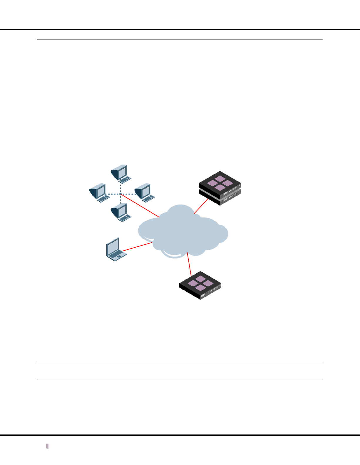
Chapter 1: Overview
Deployment Scenarios
The Infoblox devices can fit into network topologies in a variety of ways, and can provide DNS and DHCP services in
a variety of ways. This section introduces some typical ways that you can deploy your Infoblox devices:
•
Scenario 1 — Independent Infoblox Devices
•
Scenario 2 — Basic ID Grid with Independent Devices
•
Scenario 3 — Multiple ID Grids
•
Scenario 4 — Primary and Secondary Infoblox Devices
on page 26
Scenario 1 — Independent Infoblox Devices
on page 24
on page 25
on page 27
The simplest type of deployment is one that uses the devices as independent devices, as shown in
Figure 1.1 Independent Infoblox Devices
Network
Clients
Independent HA Pair
Providing DNS
Services
Internet
GUI Client
Independent Device
Providing DHCP
Services
Figure 1.1
.
In the sample deployment that is shown above, three devices are deployed as independent devices as follows:
• An independent HA pair of Infoblox devices that provides DNS services
• An independent standalone Infoblox device that provides DHCP services
A device can provide network services as an HA pair or as an independent device without being part of an ID grid.
Independent devices can provide DNS and DHCP services at the same time.
Note: When an Infoblox device is used as an independent device, that device assumes the identity of the ID grid
master in the GUI, even though it is not part of an actual grid.
24 Infoblox Administrator Guide (Rev. E) NIOS 4.0
Page 25
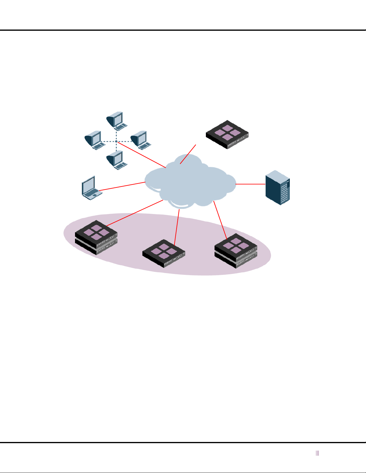
Scenario 2 — Basic ID Grid with Independent Devices
Deployment Scenarios
Multiple Infoblox devices can be deployed within an ID grid (see
Figure 1.2
). An ID grid consists of a master and at
least one member. A member can be a single Infoblox device or an HA pair that provides DNS and DHCP services
seamlessly across an entire network. The Infoblox device also provides connectivity for
external primary
name
servers that operate independently from an ID grid.
Figure 1.2 ID Grid and Independent Devices
Independent Standalone
Network
Clients
GUI
Client
Internet
ID Grid
Primary Server
Independent DNS
Secondary Server
ID Grid Master
ID Grid Member
HA Grid Member
An ID grid is controlled through a single GUI. The Infoblox device GUI allows you to centrally configure and monitor
any or all grid members. This approach reduces the time normally required to configure multiple network devices and
services because you can enter all of the settings, device data, and network services for each member using one
interface, not all the individual interfaces of each member on a recurring basis.
The Infoblox distributed database architecture enables all grid members to instantaneously receive changes to the
ID grid configuration settings because there is automatic synchronization between all of the Infoblox devices via a
secure link.
NIOS 4.0 Infoblox Administrator Guide (Rev. E) 25
Page 26
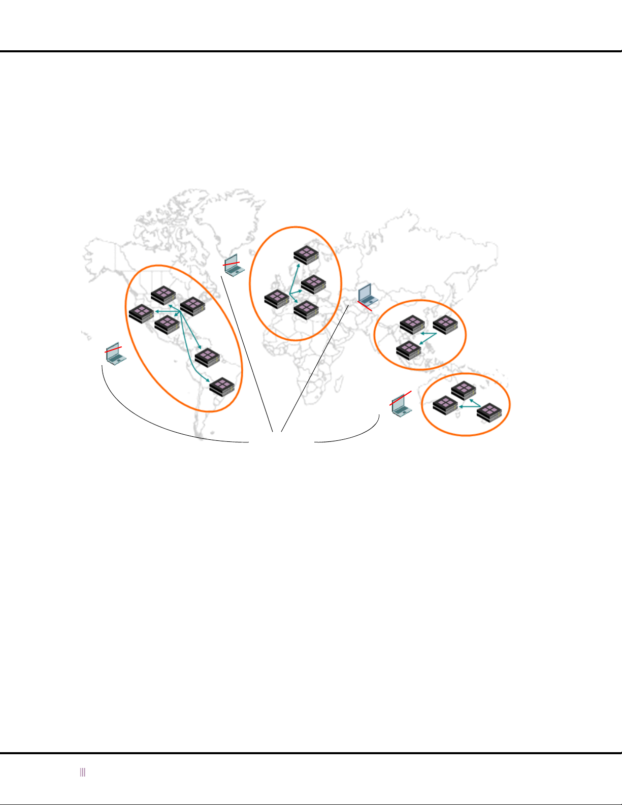
Chapter 1: Overview
Scenario 3 — Multiple ID Grids
The Infoblox device is designed to manage independently-controlled ID grids, each from a unique location (see
Figure 1.3
designed for scalable implementations to ease your network identity management needs. Each grid is centrally
managed, which significantly reduces costs associated with DNS and DHCP management tasks.
Figure 1.3 Multiple ID Grids
). For example, a global network could be managed by four independent grids. The Infoblox device is
European
ID Grid
Americas
ID Grid
Asia/PAC
ID Grid
GUI Clients
Australian
ID Grid
26 Infoblox Administrator Guide (Rev. E) NIOS 4.0
Page 27
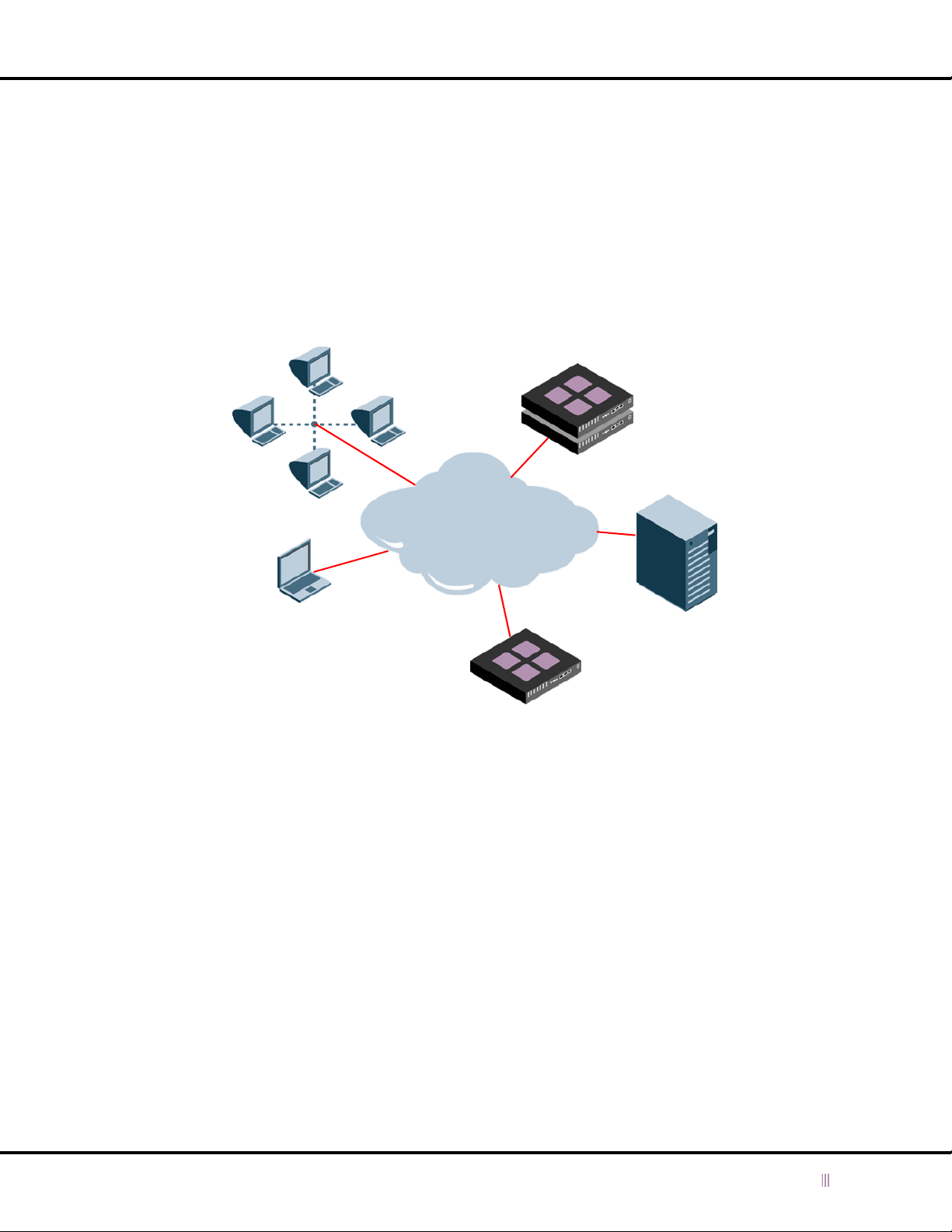
Scenario 4 — Primary and Secondary Infoblox Devices
Deployment Scenarios
The Infoblox devices can also be deployed with other network servers. For example,
Figure 1.4
shows how an Infoblox
device can operate as the primary DNS server along with two secondary name servers (a local secondary name server
and an Infoblox device external secondary server) without the Infoblox devices being part of an ID grid.
The primary DNS server is deployed inside the corporate internal firewall. In this case, the primary DNS server is an
HA pair of Infoblox devices, which provides redundancy in the event of hardware failure. The Infoblox device external
secondary name server is deployed outside of the company’s internal firewall. In this case, the Infoblox device
external secondary name server is a single Infoblox device, but it could have been an HA pair.
Figure 1.4 Primary and Secondary Servers
Network Clients
Internet
GUI Client
Independent HA Pair
(Primary Server)
DNS Server
Independent
Standalone Device
(External Secondary Server)
(Secondary Server)
Because the external secondary name server is outside of the corporate network, it provides an offsite source of name
resolution for the corporate customers and partners should the corporate connection to the Internet fail. Moreover,
even when the corporate link to the Internet is up, the external secondary server receives most of the queries for data
in the corporate external zones. This type of deployment results in the following benefits:
• The use of the corporate Internet connection for name resolution traffic is minimized.
• Name resolution by Internet name servers is faster.
Infoblox devices can also operate as forwarders or caching-only servers, either as a single node or as part of an HA
pair. A forwarder is responsible for handling queries from the internal name servers for Internet domain names
(queries that they cannot process themselves because they lack Internet connectivity).
Just as the primary DNS server is located inside the corporate internal firewall, the forwarder is also located inside
the firewall. Consequently, you must configure firewall rules that allow the forwarder to perform the following tasks:
• Send queries to the Internet name servers
• Receive responses from those Internet name servers
• Block unsolicited DNS messages from the Internet name servers
NIOS 4.0 Infoblox Administrator Guide (Rev. E) 27
Page 28

Chapter 1: Overview
28 Infoblox Administrator Guide (Rev. E) NIOS 4.0
Page 29

Chapter 2 Infoblox ID Manager GUI
This chapter introduces the two versions of the Infoblox ID Manager GUI (Graphical User Interface):
• Infoblox ID Grid Manager GUI for Infoblox devices running the DNSone, VIM (Integration Module for VitalQIP®
software), or VNS (VoIP Network Services) package with the Keystone upgrade
• Infoblox ID Device Manager GUI for Infoblox devices running the DNSone or VNS package without the Keystone
upgrade
The chapter lists the requirements for the management system you use to access an Infoblox device, explains how to
access it, and describes the components of the Infoblox ID Manager GUI, including the online help. The topics in this
chapter include:
•
Management System Requirements
•
Accessing the Infoblox GUI
—
Connecting to an Infoblox Device with JWS
—
A Single ID Manager GUI Application
•
SSL (Secure Sockets Layer) Protocol
—
Managing Certificates
•
Understanding the GUI Components
—
Main Interface Components
—
Creating a Login Banner on an Infoblox Device
on page 36
on page 30
on page 30
on page 31
on page 34
on page 35
on page 38
on page 38
on page 39
NIOS 4.0 Infoblox Administrator Guide (Rev. E) 29
Page 30

Chapter 2: Infoblox ID Manager GUI
Management System Requirements
The management system is the computer from which you configure and manage the Infoblox device. The
management system must meet the following requirements to operate an Infoblox device.
Figure 2.1 Software and Hardware Requirements for the Management System
Management System Software Requirements Management System Hardware Requirements
•GUI ACCESS
• Microsoft Internet Explorer
Microsoft Windows NT
Windows® 2000, Microsoft Windows XP
•or
• Mozilla 1.7 or higher on Linux or variants of
UNIX (Irix, Solaris, HP-UX, AIX)
•and
• Sun® Java Runtime Environment (JRE)
versions 1.5.0_06 or later*
• JWS application, which is automatically
installed with JRE 1.5.0_06 or later
•CLI ACCESS
• Secure Socket Shell (SSH) client that
supports
SSHv2
• Terminal emulation program, such as
minicom or Hilgraeve Hyperterminal
*JRE 1.5 and JRE 5.0 are basically the same version; however, the JRE 1.5 version names are more granular (1.5.0_01,
1.5.0_02, 1.5.0_03, and so on). Use JRE 1.5.0_06 or later or the latest version of JRE 5.0.
®
6.0 or higher on
®
4.0, Microsoft
®
.
•Minimum System: 500 MHz CPU with 256
MB RAM available to the product GUI, and
56 Kbps connectivity to an Infoblox device
®
• Recommended System: 1 GHz (or higher)
CPU with 512 MB RAM available for the
product GUI, and network connectivity to an
Infoblox device
• Monitor Resolution: 1024 x 768 (minimum)
to 1600 x 1200 (maximum)
Note: If the browser used to manage the device has a pop-up blocker enabled, you must turn off the pop-up blocker
for the IP address used to manage the device.
Accessing the Infoblox GUI
Before you access the Infoblox GUI, connect your device to the network as described in the user guide or quick start
guide that shipped with your product. Refer to
and powering up the device.
Note: Before proceeding, make sure your computer meets the current requirements for the GUI client as described
in
Management System Requirements
You can then access and log in to an Infoblox device using JWS (Java Web Start). You can use any computer on your
network that has the following applications:
• JRE (Java Runtime Environment) version 1.5.0_06 or later
• JWS application, which is automatically installed with JRE 1.5.0_06 or later
• Standard browser that associates JNLP (Java Network Launching Protocol) file types with the JWS
30 Infoblox Administrator Guide (Rev. E) NIOS 4.0
Hardware Information
.
on page 365 for more information on cabling
Page 31

Accessing the Infoblox GUI
The Java installation typically makes this association automatically, although not in all UNIX environments. If the
browser does not automatically associate a JNLP file with the JWS application, when you click La unch ID Gri d Ma nager
or Launch ID Device Manager, you receive a prompt. Internet Explorer running on a Windows system and Mozilla
running on a Linux system provide different prompts:
• Internet Explorer prompts you to save the JNLP file. Click Cancel, and make the file association as follows:
1. Click Start -> Control Panel -> Folder Options -> File Types -> New.
2. In the File Extension field, type JNLP, and then click Advanced.
3. From the Associated File Type drop-down list, choose JNLP File, and then click OK.
4. To close the Folder Options dialog box, click Close.
You can now continue logging in to the device.
• Mozilla prompts you to save the JNLP file or choose an application to open it.
1. Select the Open with button, and then choose Other from the drop-down list.
2. Navigate to the Java directory—typically in a standard system directory like /usr/java/ on Linux systems.
3. Open the jre1.5.0_06 (or later) subdirectory, and locate and select the JWS application, which is usually
named javaws. Although the exact path structure and directory names can differ, it might be in a directory
named javaws or bin.
You can now continue logging in to the device.
When using JWS to run the GUI application, you download the GUI application to a container within a Java sandbox
on your computer and start it from there. JWS provides mechanisms to ensure automatic updates for JRE (Java
Runtime Environment) and the GUI application.
Connecting to an Infoblox Device with JWS
To make an initial management connection to the Infoblox device:
1. Start your browser, and enter https://
entered through the LCD or serial port, or the default IP address 192.168.1.2. (For more information, see
the LCD Panel
The Infoblox device sends its server certificate to the browser to authenticate itself during the SSL (Secure
Socket Layer) handshake. Because the default certificate is self-signed, your browser does not have a trusted
CA (certificate authority) certificate or a cached Infoblox device server certificate (saved from an earlier
connection) to authenticate the device certificate. Also, the host name in the default certificate is
www.infoblox.com, which is unlikely to match the host name of your Infoblox device. Consequently, messages
appear warning that the certificate is not from a trusted certifying authority and that the host name on the
certificate is either invalid or does not match the name of the site that sent the certificate.
Note: To eliminate certificate warnings, you can replace the default self-signed certificate with a different
certificate that has the host name of your Infoblox device. You can either generate another self-signed
certificate with the right host name and save it to the CA certificate store of your browser (and, later in the
procedure, to the certificate stores for JWS and the downloaded GUI application), or request a CA-signed
certificate with the right host name and load that on the device. For information, see
on page 36.
2. Either accept the certificate just for this session or save it to the certificate store of your browser.
3. When the Infoblox device home page opens, click Launch ID Grid Manager or Launch ID Device Manager.
The browser and JWS perform the following operations:
a. The browser requests the JNLP (Java Network Launching Protocol) file from the Infoblox device and
b. JWS checks for the JNLP file in its cache and, if it finds it, compares it with the recently received JNLP file.
on page 367 and
sends the file it receives to JWS (Java Web Start).
Because this is the initial connection attempt, JWS does not yet have this file cached. In subsequent
connection attempts, comparing the newly downloaded JNLP file with the cached file can indicate
whether JWS needs to update any items that the file specifies.
ip_addr, where ip_addr
Using the Serial Console
is the IP address of the Infoblox device that you
on page 367.)
Managing Certificates
Using
NIOS 4.0 Infoblox Administrator Guide (Rev. E) 31
Page 32

Chapter 2: Infoblox ID Manager GUI
c. If JWS discovers there is no cached JNLP file or that the new JNLP file differs from the earlier file, JWS
builds an SSL tunnel to the sources specified in the JNLP file. For this initial connection, JWS must make
an SSL connection to the Infoblox device to download the GUI application.
JWS displays a security warning prompting you to accept or reject the Infoblox device certificate the
device sends to authenticate itself. If the default certificate is in use, warning messages appear stating
the certificate is not from a trusted certifying authority, and that the host name on the certificate is either
invalid or does not match the name of the site. This is the same certificate that the Infoblox device uses
to authenticate itself during all SSL handshakes.
4. Either accept the Infoblox device server certificate just for this SSL session, or save it permanently to the JWS
server certificate store.
After the SSL tunnel is established, the device begins to download the GUI application, which is signed with a
different certificate than the server certificate the device uses to authenticate itself during SSL handshakes. The
certificate authenticating the GUI application is signed by Verisign. When received by JWS, it displays a security
warning prompting you to accept or reject the signed application.
5. Do one of the following:
— Click Yes to accept the authenticity of the Infoblox ID Manager GUI application for this download.
— Click Always to accept the authenticity of the Infoblox ID Manager GUI application for this and future
downloads by saving the certificate to the JWS application certificate store.
Note: To manage server certificates in JWS, open the Java Application Cache Viewer, and then click Edit ->
Preferences -> Security -> Certificates.
JWS downloads the ID Manager GUI application and any other items it needs—or, for subsequent connections,
just the items it needs to update. (For this initial connection, JWS downloads the GUI application. It might also
download a different version of JRE. The Infoblox device supports JRE 1.5.0_06 or later.)
6. After the ID Manager GUI application download is complete, begin the login process by choosing the host name
of the Infoblox device from the Hostname drop-down list and entering the user name and password. The default
user name is admin, and the default password is infoblox.
Note: The user name and password are case-sensitive. Infoblox recommends changing them after you log in. For
more details, refer to
Adding an Admin Account
on page 47.
The ID Manager GUI application initiates an SSL connection to the Infoblox device. The device sends its server
certificate to authenticate itself to the application. If the default certificate is in use, warning messages appear
stating the certificate is not from a trusted certifying authority and that the host name on the certificate is either
invalid or does not match the name of the site.
7. Accept the certificate for this session, or save it permanently to the server certificate store of the GUI application.
Note: To manage CA and server certificates in the Infoblox ID Manager GUI application, open the GUI application
login prompt, and then click Certificates.
The SSL tunnel completes, and the login process continues. If the login is successful, the connection between
the ID Manager GUI application and the Infoblox device is complete. If the login is not successful, an error
message appears and the login prompt returns.
When the session ends, the ID Manager GUI application remains in the Java sandbox. You can launch it from this
location the next time you want to connect to the Infoblox device.
32 Infoblox Administrator Guide (Rev. E) NIOS 4.0
Page 33
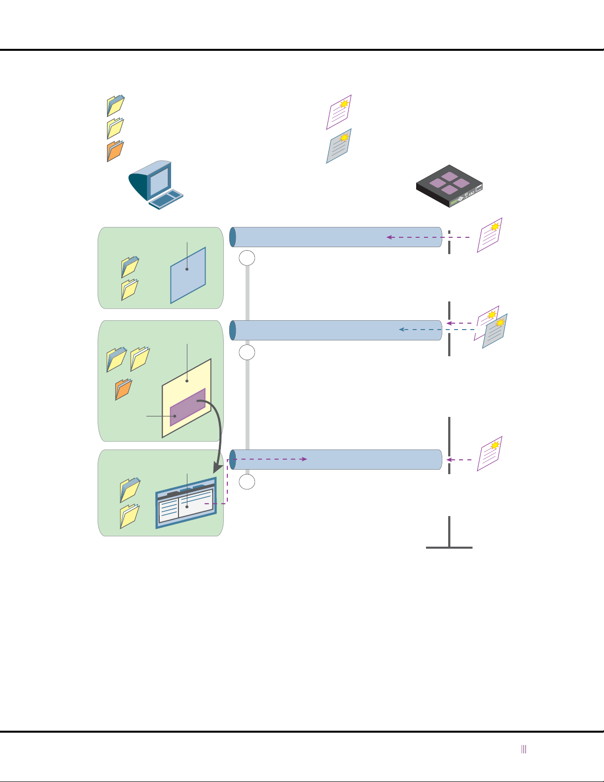
Figure 2.2 Java Web Start Initial Access
Accessing the Infoblox GUI
= CA (Certificate Authority) Certificates
= Server Certificates
= Java Application Certificates
Management Client
Browser
Certificates
Java
Certificates
ID Manager
GUI
Application
Browser
Java
Sandbox
= Infoblox Server Certificate
(authenticates the device when
establishing an SSL tunnel)
= Application Certificate
(authenticates GUI application
during download)
SSL Tunnel
JNLP File Download
1
The browser and device form an SSL
tunnel. The browser either accepts the
device certificate automatically or the
administrator accepts it manually. Then
the browser downloads the JNLP file and
passes it to the Java application.
GUI Application Download
The JNLP files instructs Java to check if it
2
has the latest GUI application and
downloads it if necessary. Java and the
device form a new SSL tunnel between
themselves. If Java automatically accepts
the two certificates—one authenticating
the device and the other authenticating the
GUI application—or if the administrator
accepts them manually, the GUI
application download proceeds.
Infoblox Device
Certificate
authenticating
the device to
management
system browser
+
Certificates
authenticating
device and
downloaded GUI
application to
Java application
GUI
Certificates
GUI
Application
Commands
The ID Manager GUI application and the
3
device form a third SSL tunnel. If the GUI
application accepts the device ce rtificate
automatically or the administrator accepts it
manually, the administrator can complete the
login and begin sending commands to the
device.
Certificates
authenticating
device to GUI
application
After you make the initial connection, you can start the ID Manager GUI application with one of these methods:
• Browser – This is identical to the initial connection. Start your browser, and enter https://
https://
ip_addr
to reach the Infoblox device.
domain_name
or
• ID Manager GUI Application Shortcut – If you created a shortcut (when prompted by JWS), double-click the
shortcut icon on your desktop. JWS checks the JNLP file and the Infoblox device resource files (.jar files
containing components of the ID Manager GUI application) for updates. JWS downloads any updated items it
might find, and then the GUI application login prompt appears.
• Java Application Cache Viewer – Open the Java Application Cache Viewer, and click the ID Manager GUI
application that you want to use. Then click either Launch Online or Launch Offline. When you select Launch
Online, JWS checks the JNLP file and the Infoblox device resource files for updates before the GUI application
connects to the device. When you select Launch Offline, JWS does not check for updates before the ID Manager
GUI application connects to the device.
NIOS 4.0 Infoblox Administrator Guide (Rev. E) 33
Page 34
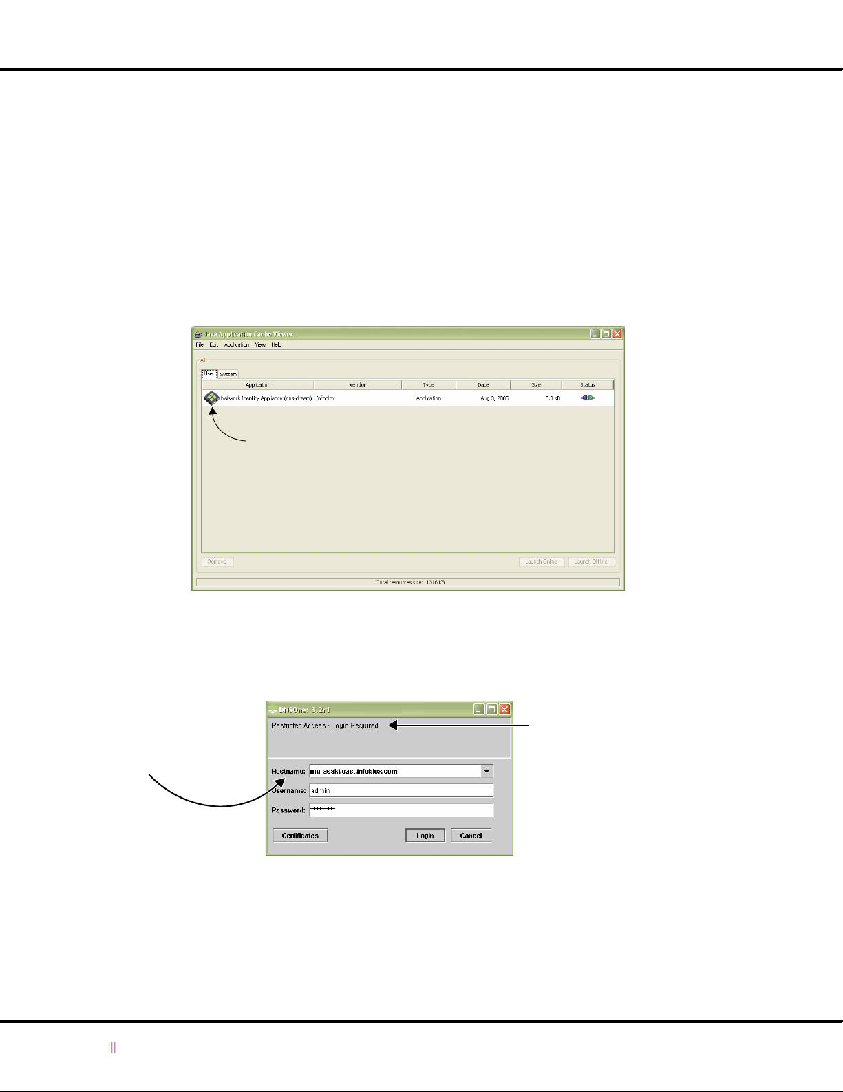
Chapter 2: Infoblox ID Manager GUI
A Single ID Manager GUI Application
JWS can use the same Infoblox GUI application for different devices as long as each device is running the same
version of software. However, each time you use the browser to initiate a connection to a different Infoblox device,
JWS downloads the GUI application to the Java sandbox—even if you have already downloaded the same version of
the application when connecting to another device. If you manage a number of independent Infoblox devices, this
can result in many unnecessary downloads. To use the same GUI application for multiple Infoblox devices running
the same software version, do not begin the connection process from the browser. Instead, do the following:
1. Use the GUI application shortcut or open the Java Application Cache Viewer.
2. Click the GUI application that you want to use, and then click Launch Online (to check for updates) or Launch
Offline (to bypass update checks).
Figure 2.3 Java Application Cache Viewer
GUI Application for
the Infoblox Device
3. When the login prompt appears, either select an existing host name from the Hostname drop-down list, or type
a new host name in the Hostname field. Then enter the correct user name and password, and click .
Figure 2.4 GUI Application Login Prompt
Choose an existing host
name from the drop-down
list, or type a new host name
in the Hostname field.
Custom banner text (if defined)
appears under the words
Restricted Access - Login Required
as soon as you enter a valid IP
address or DNS name in the
Hostname field.
Entering an invalid IP address or
DNS name, causes JWS to hang.
If JWS does not have the right version of the GUI application for an Infoblox device to which you connect—and you are
launching the application online—then JWS downloads it. For example, if another administrator upgrades the
software on an Infoblox device for which you previously downloaded an ID Manager GUI application and you then log
in through JWS, the ID Manager GUI application on your computer no longer matches the software on the Infoblox
device. JWS then downloads the correct application (or just the changed components of the application that it needs
to update to the newer version).
34 Infoblox Administrator Guide (Rev. E) NIOS 4.0
Page 35
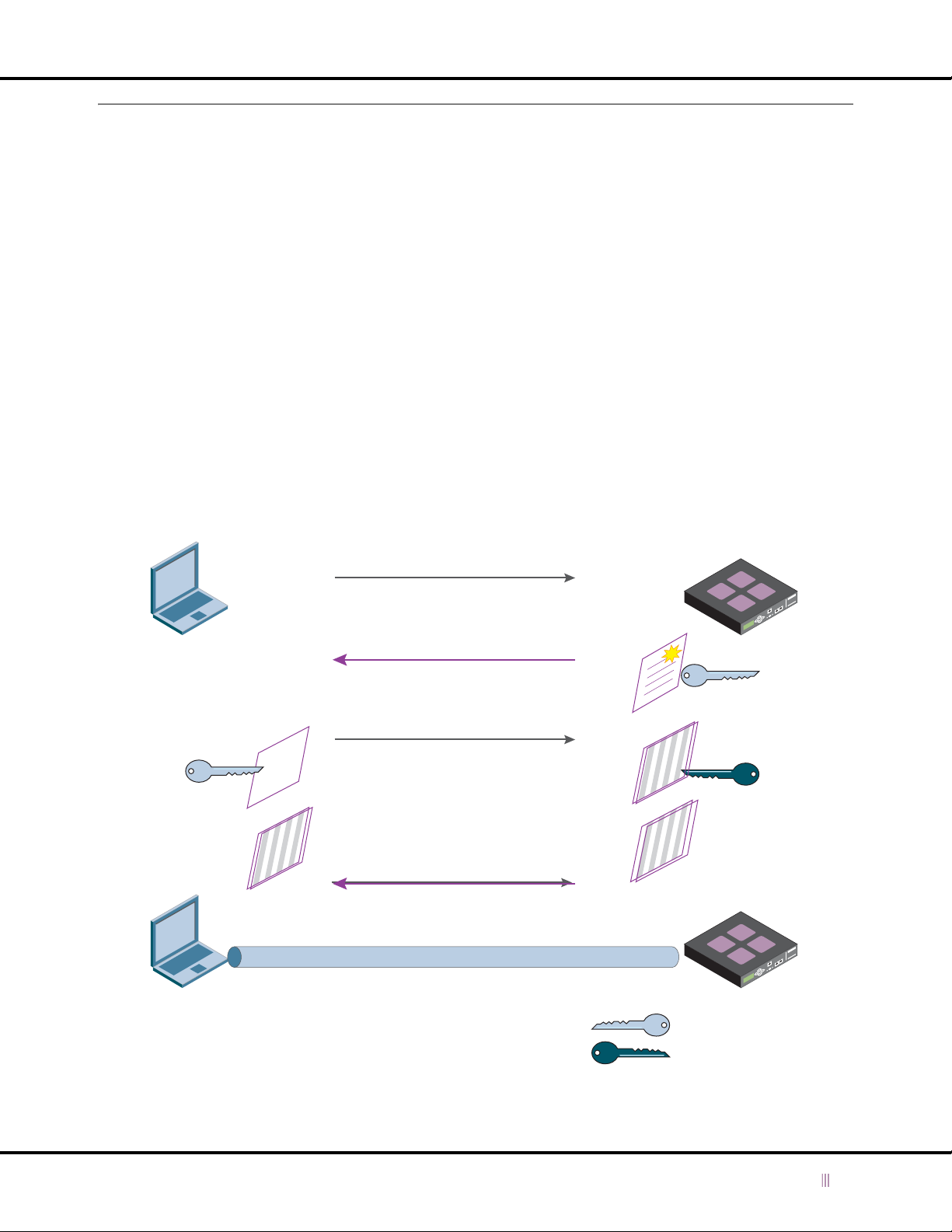
SSL (Secure Sockets Layer) Protocol
SSL (Secure Sockets Layer) Protocol
When you log in to the Infoblox device, your computer makes an HTTPS (Hypertext Transfer Protocol over Secure
Sockets Layer protocol) connection to the Infoblox device. HTTPS is the secure version of HTTP, the client-server
protocol used to send and receive communications throughout the Web. HTTPS uses SSL (Secure Sockets Layer) to
secure the connection between a client and server. SSL provides server authentication and encryption. The Infoblox
device supports SSL versions 2 and 3.
When a client first connects to a server, it starts a series of message exchanges, called the SSL handshake. During
this exchange, the server authenticates itself to the client by sending its server certificate. A certificate is an electronic
form that verifies the identity and public key of the subject of the certificate. (In SSL, the subject of the certificate is
the server.) Certificates are typically issued and digitally signed by a trusted third party, the Certificate Authority (CA).
A certificate contains the following information: the dates it is valid, the issuing CA, the server name, and the public
key of the server.
A server generates two distinct but related keys: a public key and a private key. During the SSL handshake, the server
sends its public key to the client. Once the client validates the certificate, it encrypts a random value with the public
key and sends it to the server. The server decrypts the random value with its private key.
The server and the client use the random value to generate the master secret, which they in turn use to generate
symmetric keys. The client and server end the handshake when they exchange messages indicating that they are
using the symmetric keys to encrypt further communications.
Figure 2.5 SSL Handshake
Plain
Text
Cipher
Text
Client contacts the Infoblox device and recommends
certain parameters, such as SSL version, cipher
settings, and session-specific data.
The device either agrees or recommends other
parameters. It also sends its certificate which
contains its public key.
Client encrypts random number with the public
key and sends it to the device. The device uses
its private key to decrypt the message.
The client and the device generate the master
secret, and then the symmetric keys.
The client and the device agree to encrypt all
messages with symmetric keys.
Cipher
Text
Cipher
Text
The client and the device send all their messages through the SSL tunnel
which uses the cipher settings and encryption to secure their connection.
Public Key
Private Key
NIOS 4.0 Infoblox Administrator Guide (Rev. E) 35
Page 36

Chapter 2: Infoblox ID Manager GUI
Managing Certificates
The Infoblox device generates a self-signed certificate when it first boots up. (A self-signed certificate is signed by the
subject of the certificate, and not by a CA.) This is the default certificate. When your computer first connects to the
Infoblox device, it sends this certificate to authenticate itself to your browser.
Because the default certificate is self-signed, your browser does not have a trusted CA certificate or a cached Infoblox
device server certificate (saved from an earlier connection) to authenticate the device certificate. Also, the host name
in the default certificate is www.infoblox.com, which is unlikely to match the host name of your device. Consequently,
messages appear warning that the certificate is not from a trusted certifying authority and that the host name on the
certificate is either invalid or does not match the name of the site that sent the certificate. Either accept the certificate
just for this session< or save it to the certificate store of your browser.
To eliminate certificate warnings, you can replace the default self-signed certificate with a different certificate that has
the host name of your device. After initial login, you can do one of the following:
• Generate another self-signed certificate with the correct host name and save it to the certificate store of your
browser.
• To generate a self-signed certificate, see
• Request a CA-signed certificate with the correct host name and load that on the Infoblox device.
• To use a certificate from a CA, generate a certificate signing request as described in
Signing Request
Importing a Certificate
on page 37. When you receive the certificate from the CA, you can import it as described in
on page 37.
Generating a Self-Signed Certificate
on page 36.
Generating a Certificate
Generating a Self-Signed Certificate
You can replace the default certificate with a self-signed certificate that you generate. When you generate a
self-signed certificate, you can specify the correct host name and change the public/private key size, enter valid
dates and specify additional information specific to the device. If you have multiple devices, you can generate a
certificate for each device with the appropriate host names.
To generate a self-signed certificate:
1. For an ID grid: From the ID Grid perspective, click + (for
Certificate -> Generate Self-Signed Certificate.
For an independent device or HA pair: From the ID Device perspective, click
Certificate -> Generate Self-Signed Certificate.
2. In the
3. Click OK to close the
4. Click the Save icon.
Create Self-Signed Certificate
— Key Size: Select either 2048 or 1024 for the length of the public key.
— *Days Valid: Specify the validity period of the certificate.
— *Common Name: Specify the domain name of the Infoblox device. You can enter a fully qualified domain
name (FQDN).
— Organization: Type the name of your company.
— Organizational Unit: Type the name of your department.
— Locality: Type a location, such as the city or town of your company.
— State or Province: Type the state or province.
— Country Code: Enter the 2-letter code that identifies the country, such as US.
— Administrator’s E-mail Address: Enter the e-mail address of the device administrator.
— Comment: Enter additional notes.
An asterisk (*) indicates the field is required.
dialog box, enter the following:
Create Self-Signed Certificate
The Infoblox device logs you out, or you can log out yourself. When you log in to the device again, it uses the
certificate you generated.
id_grid
dialog box.
) -> + (for Members ) ->
hostname
grid_member
) -> Tools -> HTTPS
-> Tools -> HTTPS
36 Infoblox Administrator Guide (Rev. E) NIOS 4.0
Page 37

SSL (Secure Sockets Layer) Protocol
Generating a Certificate Signing Request
You can generate a certificate signing request (CSR) that you can use to obtain a signed certificate from your own
trusted CA. Once you receive the signed certificate, you can import it into the Infoblox device, as described in
Importing a Certificate
To generate a CSR:
1. For an ID grid: From the ID Grid perspective, click + (for
Certificate -> Generate Signing Request.
or
For an independent device or HA pair: From the ID Device perspective, click
Certificate -> Generate Signing Request.
2. In the
3. Click OK to close the
4. In the
Create Certificate Signing Request
— Key Size: Select either 2048 or 1024 for the length of the public/private key pair.
—*Common Name: Specify the domain name of the Infoblox device. You can enter a fully qualified domain
name (FQDN).
— Organization: Type the name of your company.
— Organizational Unit: Type the name of your department.
— Locality: Type a location, such as the city or town of your company.
— State or Province: Type the state or province.
— Country Code: Enter the 2-letter code that identifies the country, such as US.
— Administrator’s E-mail Address: Enter the e-mail address of the device administrator.
— Comment: Enter additional notes.
An asterisk (*) indicates the field is required.
Download filename
click Save.
.
dialog box, enter the following:
Create Certificate Signing Request
dialog box, navigate to where you want to download the CSR, enter the file name and
id_grid
) -> + (for Members ) ->
dialog box.
grid_member
hostname
-> Tools -> HTTPS
) -> Tools -> HTTPS
Importing a Certificate
You can replace the default server certificate with a signed certificate from your own trusted CA. First, generate a
certificate signing request as described in
When you import a certificate, the Infoblox device finds the matching CSR and takes the private key associated with
the CSR and associates it with the newly imported certificate. The device then automatically deletes the CSR.
To import a certificate:
1. For an ID grid: From the ID Grid perspective, click + (for
Certificate -> Generate Signing Request.
or
For an independent device or HA pair: From the ID Device perspective, click
Certificate -> Generate Signing Request.
2. Navigate to where the certificate is located and click Open.
The device imports the certificate and logs out. When you log in to the device again, it uses the certificate you
imported.
Generating a Certificate Signing Request
id_grid
) -> + (for Members ) ->
hostname
on page 37.
grid_member
) -> Tools -> HTTPS
-> Tools -> HTTPS
NIOS 4.0 Infoblox Administrator Guide (Rev. E) 37
Page 38
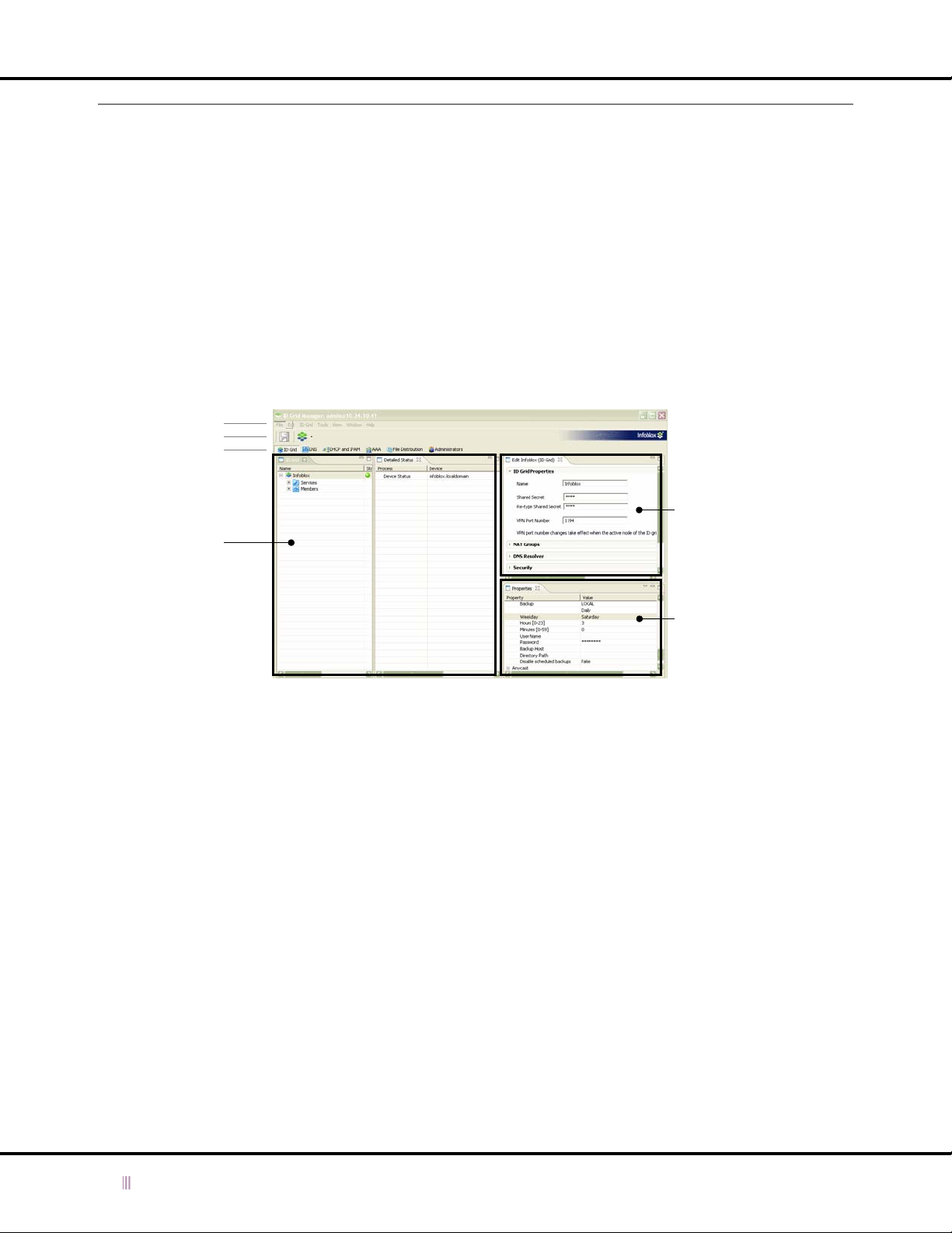
Chapter 2: Infoblox ID Manager GUI
Understanding the GUI Components
You can view data and configuration settings and make configuration changes through the Infoblox GUI using the
following two methods:
• ID Device Manager: When an Infoblox device functions as an independent device, you launch the ID Device
Manager to access the GUI. The name appears in the title bar of the browser window.
• ID Grid Manager: When the device is in an ID grid, you log in to the grid master and launch the ID Grid Manager.
The name appears in the title bar of the browser window.
Main Interface Components
The following figure illustrates the typical layout of the Infoblox GUI. You can detach and move the GUI components
and customize the GUI as necessary.
Figure 2.6 Infoblox GUI Overview
Menu
Tool Bar
Perspective
Editor
Panels
View and select items
to edit.
Detach and move panels,
viewers and editors to
customize the GUI layout.
Enter and edit information.
Properties Viewer
View object properties.
Menu
Each item in the menu is a drop-down list of available options. The menu items change dynamically according to the
perspective you are in.
Tool Bar
The tool bar contains a Save icon which you click to save your configuration changes, and a Restart Services icon,
which you click to restart services on a device or ID grid.
Perspectives
The Infoblox GUI application provides the following perspectives for each functional area.
• ID Device: In this perspective, you configure an independent device and set its operational parameters.
• ID Grid: In this perspective, you configure an ID grid and set operational parameters. A Keystone license is
required for this feature.
• DNS: In this perspective, you enable and configure DNS services on the device or grid.
• DHCP and IPAM: In this perspective, you enable and configure DHCP service and IP Address Management
features.
• Administrators: In this perspective, you configure administrators.
• File Distribution: In this perspective, you enable and configure TFTP (Trivial File Transfer Protocol) services.
• AAA: In this perspective, you configure RADIUS proxy services.
• VitalQIP: In this perspective, you can configure the device to function as a VitalQIP remote server. A VitalQIP
license is required for this feature.
38 Infoblox Administrator Guide (Rev. E) NIOS 4.0
Page 39

Understanding the GUI Components
Panel
Panels list objects that you can select and edit. You can expand or collapse lists by selecting the + or - sign beside
an object.
Shortcuts
— Select an object and right-click to display options.
— Double-click an item to edit it (open its editor).
— Ctrl+click to select multiple items.
Editor
You can enter information and configure objects in an editor. You can open multiple editors at one time. After you
enter information in an editor, you must click the Save icon to save your changes.
Properties Viewer
Viewers display information about a selected object. You cannot edit or select objects in a viewer. However, you can
expand, collapse, detach and move viewers to different locations.
Online Help
The Infoblox device ships with online help you can access from anywhere in the GUI.
• To access the main Help system, click Help -> Help Contents.
• To access Help for the active panel, editor, or viewer, click Help -> Dynamic Help. A window is active when its title
bar is highlighted.
• To access Help for a dialog box, click the question mark (?) icon in the bottom left corner of the dialog box.
In addition, you can download the Infoblox Administrator Guide by clicking Help -> Download Admin Guide.
Creating a Login Banner on an Infoblox Device
To create a statement that appears on the top of the
is useful for posting security warnings or user-friendly information well above the user name and password fields on
the
Login
screen. A login banner message can be up to 3000 characters long. In an ID grid, perform this task on the
grid master.
To create a login banner.
1. From the ID Grid perspective, click
or
From the ID Device perspective, click
2. In the
3. Select Enable Login Banner and enter the text you want displayed in the Banner Text field.
4. Click the Save icon.
ID Grid
(or
ID Device
) editor, click Security.
id_grid
hostname
Login
screen, follow the procedures in this section. This function
-> Edit -> Grid Properties.
-> Edit -> ID Device Properties.
NIOS 4.0 Infoblox Administrator Guide (Rev. E) 39
Page 40

Chapter 2: Infoblox ID Manager GUI
40 Infoblox Administrator Guide (Rev. E) NIOS 4.0
Page 41

Chapter 3 Managing Administrators
This chapter describes the various tasks associated with setting up admin groups and accounts. These tasks apply
to both independent and ID grid installations. This chapter contains the following sections:
•
Local and Remote Admin Accounts
•
Local Admin Groups and Accounts
—
Creating a Superuser Admin Group
—
Creating a Limited-Access Admin Group
—
Adding an Admin Account
—
Modifying and Removing an Admin Account
•
Authentication Using RADIUS
—
Configuring RADIUS Server Authentication
—
Configuring a RADIUS Server
•
Remote Admin Groups and Accounts
—
Configuring a RADIUS Server for Remote Admin Groups
—
Creating a Remote Admin Group
—
Configuring a RADIUS Server for Remote Admin Accounts
•
Changing Password Length Requirements
•
Notifying Administrators
on page 56
on page 42
on page 44
on page 44
on page 45
on page 47
on page 48
on page 48
on page 49
on page 52
on page 52
on page 53
on page 54
on page 55
on page 55
NIOS 4.0 Infoblox Administrator Guide (Rev. E) 41
Page 42

Chapter 3: Managing Administrators
Local and Remote Admin Accounts
Infoblox uses the concept of administrator groups to which you add one or more individual administrators. The
administrators inherit the privileges and properties for the group to which they belong. You can add the
administrators locally (that is, on the Infoblox device) or remotely (on a RADIUS server). The tasks involved in storing
administrator accounts locally and remotely are listed in
Table 3.1 Storing Admin Accounts Locally and Remotely
Infoblox device RADIUS server
• Use the default admin group
(“admin-group”) or define a new group
To store admin
accounts locally
• Set the privileges and properties for the
group
• Add admin accounts to the group
Table 3.1
.
• Configure communication settings with
a RADIUS server
If you use admin groups on the RADIUS
server:
• Use an existing admin group or define a
new one
To store admin
accounts remotely
Some general points about admin groups and admin accounts:
• Regardless of the location of an admin account, the group from which the admin receives privileges and
properties is stored locally.
• An admin account can only belong to one admin group at a time.
• All local admin accounts must belong to a local admin group.
• Remote admin accounts can—but do not have to—belong to a remote admin group.
— If a remote admin account belongs to a remote admin group, the name of the remote admin group must
match the name of a local admin group.
— If the name of a remote admin group does not match the name of a local group and there is a default admin
group on the Infoblox device, the device applies the privileges and properties of the default group to
admins belonging to the remote group.
— If the name of a remote admin group does not match the name of a local group and there is no default
admin group on the device, admins belonging to the remote group cannot access the device.
— If a remote admin account does not belong to a remote admin group, you must specify a default admin
group on the Infoblox device from which the remote admin account receives its privileges and property
settings.
For an illustration showing the relationship of local and remote admin accounts, admin groups, and privileges and
properties, see
• Set the privileges and properties for the
group
If you do not use admin groups on the
RADIUS server:
• Assign an admin group as the default
Figure 3.1
on page 43.
• Configure communication settings with
the Infoblox device
If you use admin groups on the RADIUS
server:
• Import Infoblox VSAs (vendor-specific
attributes)
• Define an admin group with the same
name as that on the Infoblox device
• Define admin accounts and link them to
an admin group
If you do not use admin groups on the
RADIUS server:
• Define admin accounts
42 Infoblox Administrator Guide (Rev. E) NIOS 4.0
Page 43
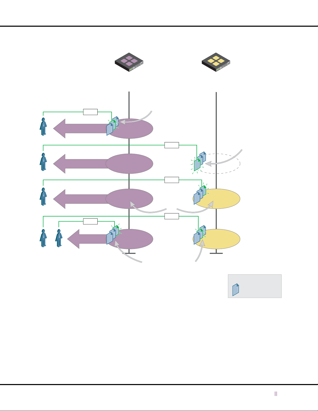
Figure 3.1 Privileges and Properties Applied to Local and Remote Admin Accounts
Infoblox Device RADIUSone
Local and Remote Admin Accounts
Admin
Users
Access privileges and properties come
from local admin group definitions.
Login
Adam
Balu
Christine
Login
EveDan
Local
Admin
Groups
The Infoblox device first
checks if an admin account
is stored locally.
Admin-Group1
Default
Admin-Group
Admin-Group2
Admin-Group3
Login
Login
Group
names
must
match.
Login
Remote
Admin
Groups
When remote admin
accounts are not in
an admin group (or in a
group whose name does
not match that of a local
group), the Infoblox
device applies the
Default Admin-Group
privileges and properties.
Admin-Group2
Admin-Group3
When admin
accounts are in
a remote admin
group, there must
be a local admin
group with the
same name so
that the device can
apply the privileges
and properties to
the admin
belonging
to that group.
Assigned from local admin group definitions:
Access Privileges
(for Infoblox views, zones, networks,
members and DHCP lease history)
Properties
(for page and tree sizes)
To set up local admin accounts, see
remote RADIUS server, see
NIOS 4.0 Infoblox Administrator Guide (Rev. E) 43
Remote Admin Groups and Accounts
Local Admin Groups and Accounts
There can be admin
accounts in a local and
remote admin group with
the same group name.
on page 44. To store admin accounts on a
on page 52.
Note:
= Admin Account
Page 44

Chapter 3: Managing Administrators
Local Admin Groups and Accounts
All local admin accounts must belong to a local admin group. The privileges and properties that you set for the group
apply to all the admin accounts that you assign to that group.
There are three types of privilege settings:
• Superuser – Superuser admin groups provide their members with unlimited access and control of all the
operations that an Infoblox device performs. There is a default superuser admin group with one superuser
admin. You can add users to this default admin group and create additional admin groups with superuser
privileges.
• Limited-Access – Limited-access admin groups provide their members with read-only or read/write access to
specific zones, networks, and ID grid members. You can create admin groups with specific access privileges.
• ALL USERS – The ALL USERS group is a default group in which you define global privileges for all limited-access
users. This group implicitly includes all limited-access users configured on the device.
You can configure multiple admin accounts for local or remote authentication. However, there must always be one
superuser admin account stored in the local database to ensure that at least one administrator can log in to the
device in case the Infoblox device loses connectivity to the RADIUS server.
Creating a Superuser Admin Group
To create a superuser admin group:
1. Log in as a superuser. (Only a superuser can create admin groups.)
2. From the Administrators perspective, click Groups -> Edit -> Add Group.
3. In the
4. Click the Save icon to save your changes.
Add Administrator Group
— Group Name: Enter the name for the admin group.
— Comment: Enter pertinent information about the group, such as location or department. The data entered
here appears in the list view of the GUI when you select an admin group name in the tree view.
— Superuser: Select this check box to grant the admin accounts that you assign to this group full authority to
view and configure all types of data. Clear this check box to set limited privileges for this admin group.
— Allow DHCP lease history access: Select this check box to allow administrators that belong to this group to
view the DHCP lease history log. Note that an administrator who has the right to view the DHCP lease history
log can access the entire log and see log entries for networks and ID grid members that he or she might
otherwise not have access. Clear this check box to restrict access to the DHCP lease history log for
administrators that belong to this group.
— Page Size: Enter a value for the number of lines of data that you want a single GUI list view to contain for
administrators that belong to this group. When there is a lot of data, you can improve the display
performance by setting a smaller page size, such as 100 instead of 1000. You can set the page size from 10
to 2000. The default page size is 100.
— Disable this admin group: Select this check box to retain an unactivated profile for this admin group in the
configuration. For example, you might want to define a profile for recently hired administrators who have
not yet started work. Then when they do start, you simply need to clear this check box to activate the
profile.
editor, click Group Properties and enter the following:
44 Infoblox Administrator Guide (Rev. E) NIOS 4.0
Page 45

Local Admin Groups and Accounts
Creating a Limited-Access Admin Group
When you create a limited-access admin group, you determine the resources—networks, zones, and ID grid
members—that administrators in that group can access with read-only or read/write privileges.
To create a limited-access admin group:
1. Log in as a superuser. (Only a superuser can create admin groups.)
2. From the Administrators perspective, click Groups -> Edit -> Add Group.
3. Click Group Properties and enter the following:
— Complete the fields as described in
— Superuser: Clear this check box to set limited privileges for this admin group.
4. Click Group Privileges.
5. Click Add, enter the following in the Group Permissions dialog box, and then click OK:
— Select the object for which you want to grant privileges. For example, to grant privileges to the
test.corp100.com zone, click + (for All Zones) -> + (for default) -> + (for Forward Mapping Zones) ->
test.corp100.com.
— Select the appropriate privileges: Read-Only, Read-Write, Deny.
6. Click OK to close the
The object for which you set access privileges appears in the Privileges list in the
editor.
7. Click the Save icon to save your changes.
Group Permissions
Creating a Superuser Admin Group
dialog box.
.
Add Administrator Group
Assigning Privileges to All Users
By default, granting read-only or read/write privileges for a zone also grants read-only privileges for all zones and
subzones in the same view. (For information about Infoblox views, see
To limit access to zones within a view, you must do the following:
• Grant read-only or read-write privileges for specific zones to the appropriate user groups.
• Add deny rules for each zone in the same view in the ALL USERS group.
In the example shown in
corp100.com zone has two subzones, eng.corp100.com and finance.corp.100.com. The corp200.com zone also has
two subzones, eng.corp200.com and finance.corp200.com. You create Admin Group A and grant it read/write
privileges for the eng.corp100.com zone, as follows:
1. From the Administrators perspective, click Groups -> Edit -> Add Group.
2. Click Group Properties and enter the following:
— Group Name: Admin Group A
— Complete the other fields as described in
— Superuser: Clear this check box.
3. Click Group Privileges.
4. Click Add, enter the following in the Group Permissions dialog box, and then click OK:
— Select Read/Write.
— Click + (for All Zones) -> + (for default) -> + (for Forward Mapping Zones) -> + (for corp100.com) ->
eng.corp100.com.
5. Click the Save icon to save your changes.
6. View the group privileges of Admin Group A by selecting it and clicking View -> Properties. The
section displays the privileges of Admin Group A, which are the read/write privileges to eng.corp100.com that
you configured and the read-only privileges to the default view that the device automatically created.
Figure 3.2
, two zones, corp100.com and corp200.com are in the default view. The
Creating a Superuser Admin Group
Using Infoblox Views
.
on page 170.)
Group Privileges
NIOS 4.0 Infoblox Administrator Guide (Rev. E) 45
Page 46
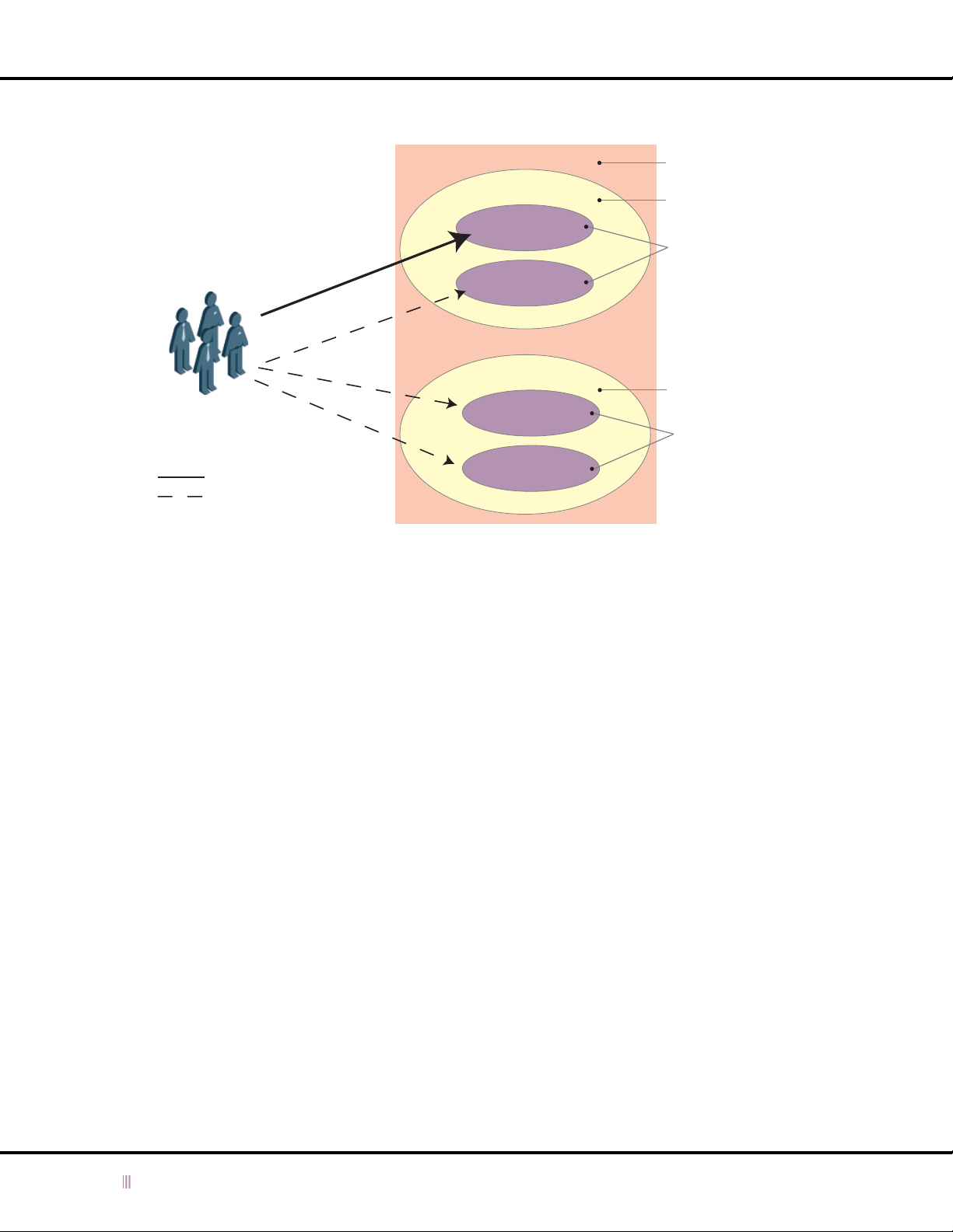
Chapter 3: Managing Administrators
Figure 3.2 Admin Group with Privileges to All Zones in Default View
When you grant read-write
privileges for Admin Group A to the
eng.corp100.com zone, the device
automatically grants read-only
privileges to all the other zones in
the same view.
Admin Group A
Read/Write Privileges
Read-Only Privileges
Default View
corp100.com
eng.corp100.com
finance.corp100.com
corp200.com
eng.corp200.com
finance.corp200.com
View
Zone
Subzones
Zone
Subzones
If you do not want admin groups, such as Admin Group A in the example, to receive automatically read-only access
to all zones in the same view as a zone to which they have access, you must create a deny rule for each zone in the
view in the ALL USERS group. Setting a deny rule for each zone in a view in the ALL USERS group effectively denies
access to zones for which admin groups do not have explicit read-only or read/write privileges. Therefore, in the
example, in addition to granting privileges to Admin Group A, you must also create deny rules in the ALL USERS group
for all the other zones in the default view.
Rules set at the zone level override rules set at the subzone level. Therefore, creating a deny rule for a particular zone,
automatically denies access to all its subzones, even if an admin group has explicit read-only or read-write privileges
to the subzone. If you want to grant some admin groups read-only and read-write privileges to subzones, you must
set the deny rules at the subzone level only.
In the example, you set a deny rule for each subzone, as follows:
1. From the Administrators perspective, click + (for Groups) -> ALL USERS -> Edit -> Group Properties.
2. In the Administrator Group editor, click Group Privileges -> Add.
3. In the Group Permissions dialog box, enter the following and click OK:
— Deny: Select check box.
— Click + (for All Zones) -> + (for default) -> + (for Forward Mapping Zones) -> + (for corp100.com) ->
finance.corp100.com.
4. Repeat steps 2 to 4 for eng.corp200.com and finance.corp200.com.
5. Click the Save icon.
Admin Group A now has read/write privileges to eng.corp100.com and no access to the other zones in the default
view, as shown in
Figure 3.3
on page 47.
46 Infoblox Administrator Guide (Rev. E) NIOS 4.0
Page 47
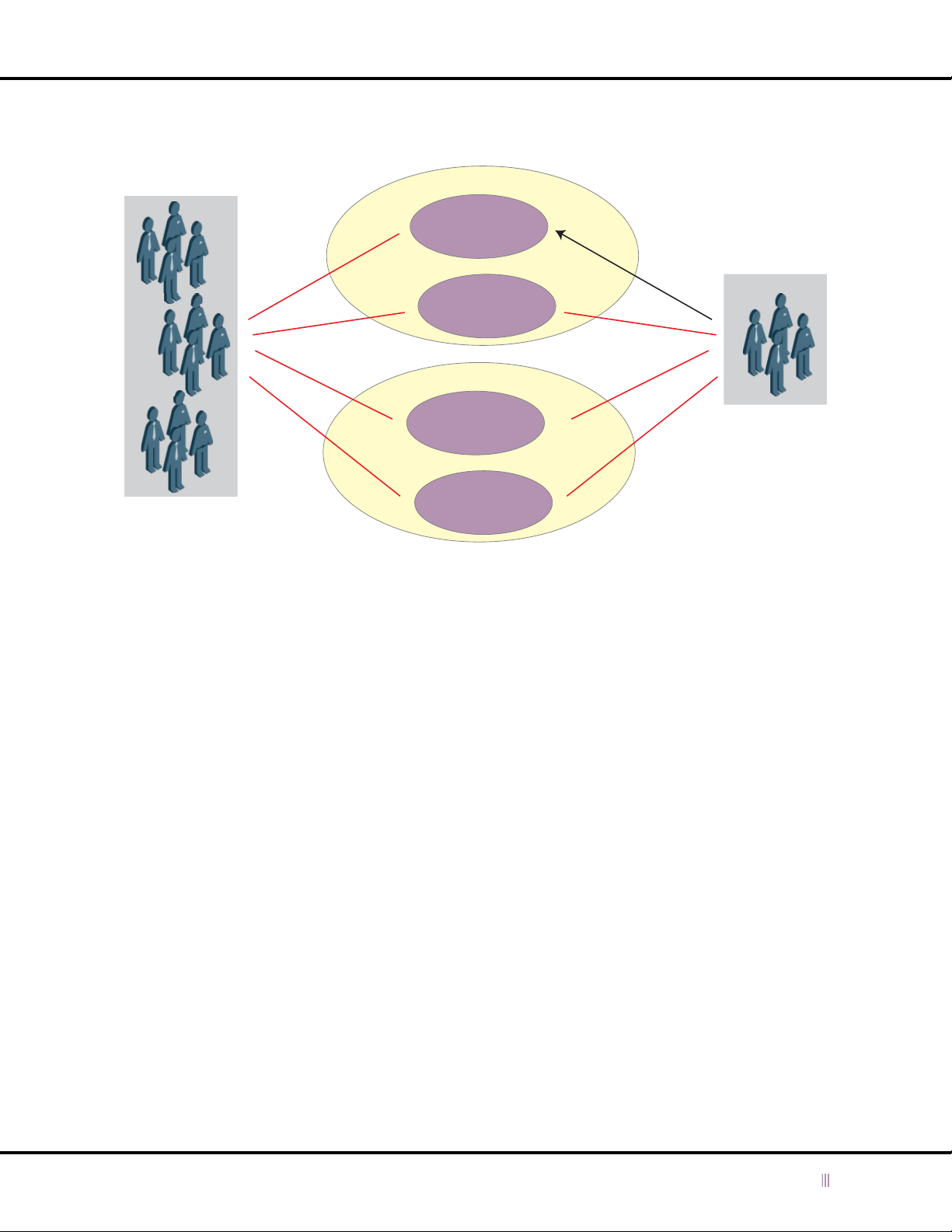
Figure 3.3 All Users Group with Read-Only Deny Rules
X
finance.corp100.com
X
Local Admin Groups and Accounts
Default View
corp100.com
eng.corp100.com
X
corp200.com
Admin Group A
ALL USERS
X
eng.corp200.com
finance.corp200.com
X
X
X
Adding an Admin Account
To create an admin account and add it to an admin group:
1. Log in using a superuser account.
2. From the Administrators perspective, click + (for Groups) ->
3. Enter the following:
— Admin Name: Enter the name of the administrator. This is the name that the administrator uses to log in.
— Group: Choose the admin group of the administrator. An admin can belong to only one admin group at a
time.
— Email Address: Enter the e-mail address for this administrator. Note that this address simply provides
contact information. The Infoblox device does not send e-mail notifications to it. You define the e-mail
address for notifications on the Email section of the ID Device or ID Grid Editor.
— Comment: Enter pertinent information about the administrator, such as location or department.
— Password: Enter a password for the administrator to use when logging in.
— Re-Type Password: Enter the same password.
— Override admin group page size: Clear this check box to use the same page length specified for the admin
group. Select this check box to enter a different page length.
— Page Size: Enter a value for the number of lines of data that you want a single GUI list view to contain for
this administrator. When there is a lot of data, you can improve the display performance by setting a smaller
page size, such as 100 instead of 1000. You can set the page size from 10 to 2000. The default page size is
100.
— Disable this admin: Select this check box to retain an unactivated profile for this administrator in the
configuration. For example, you might want to define a profile for a recently hired administrator who has not
yet started work. Then when he or she does start, you simply need to clear this check box to activate the
profile.
4. Click the Save icon to save your changes.
admin_group
-> Edit -> Add Local Admin.
NIOS 4.0 Infoblox Administrator Guide (Rev. E) 47
Page 48
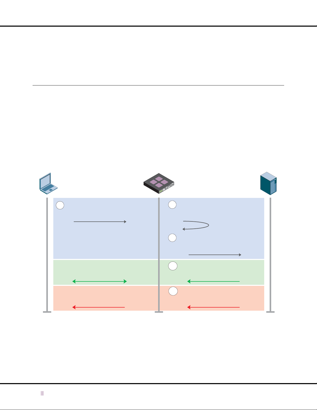
Chapter 3: Managing Administrators
Modifying and Removing an Admin Account
You can modify and remove the admin accounts you create, but you can only partially modify the default superuser
account “admin”—and only when you are logged in as the superuser “admin”. Furthermore, because there must
always be a superuser account on the device, you can only remove the default “admin” account after you create
another superuser account.
Authentication Using RADIUS
RADIUS provides authentication, accounting, and authorization functions. The Infoblox device supports
authentication using the following RADIUS servers: RADIUSone, FreeRADIUS, Microsoft, Cisco, and Funk.
You must be a superuser to configure admin accounts and RADIUS server properties on the Infoblox device. When
you configure the device to authenticate administrators using a RADIUS server, the device acts similarly to a network
access server (NAS), which is a RADIUS client that sends authentication and accounting requests to the RADIUS
server.
Figure 3.4 Authentication using a RADIUS server
Figure 3.4
illustrates the authentication process.
Administrator
1
A user makes an HTTPS connection
to the Infoblox device and sends a
user name and password.
The device lets the user log in and
applies the authorization profile.
The device does not allow the user to
log in.
Infoblox Device RADIUS Server
The device checks if an admin account
2
in its local database matches the login
name. It does not find a match.
The device sends an Access-Request
3
packet to the RADIUS server.
If the RADIUS server authenticates the
4a
user, it sends back an Access-Accept
packet.
If the RADIUS server rejects the
4b
authentication request, it sends back an
Access-Reject packet.
48 Infoblox Administrator Guide (Rev. E) NIOS 4.0
Page 49

Authentication Using RADIUS
Authentication
When you configure the Infoblox device for remote authentication with a RADIUS server, you must specify the
authentication method of the RADIUS server. You can specify either PAP (Password Authentication Protocol) or CHAP
(Challenge Handshake Authentication Protocol).
PAP tries to establish the identity of a host using a two-way handshake. The client sends the user name and password
in clear text to the Infoblox device. The device uses a shared secret to encrypt the password and sends it to the
RADIUS server in an Access-Request packet. The RADIUS server uses the shared secret to decrypt the password. If the
decrypted password matches a password in its database, the user is successfully authenticated and allowed to log
in.
With CHAP, when the client tries to log in, it sends its user name and password to the Infoblox device. The device then
creates an MD5 hash of the password together with a random number that the device generates. It then sends the
random number, user name, and hash to the RADIUS server in an Access-Request package. The RADIUS server takes
the password that matches the user name from its database and creates its own MD5 hash of the password and
random number that it received. If the hash that the RADIUS server generates matches the hash that it received from
the device, then the user is successfully authenticated and allowed to log in.
Authorization
You can specify authorization privileges for an admin group on the Infoblox device only. The device ignores
authorization settings from the RADIUS server. Therefore, you must configure all admin groups on the Infoblox device,
regardless of where the admin accounts that belong to those groups are stored—on the Infoblox device or on the
RADIUS server. For information about specifying superuser and limited-access authorization privileges, see
a Superuser Admin Group
on page 44 and
Creating a Limited-Access Admin Group
on page 45.
Creating
Accounting
You can enable the accounting feature on the RADIUS server to track an administrator’s activities during a session.
After an administrator successfully logs in, the device sends an Accounting-Start packet to the RADIUS server.
Configuring RADIUS Server Authentication
To configure the Infoblox device to authenticate administrators using a RADIUS server, you must configure admin
accounts for these administrators on the RADIUS server. Then, on the Infoblox device, you must do the following:
• Enable RADIUS authentication and, optionally, modify the default settings.
• Add one or more RADIUS servers.
• Define one or more admin groups and specify its privileges and settings. If these names match admin group
names defined on the RADIUS server, the Infoblox device applies these privileges and settings to users
belonging to those groups on the RADIUS server.
• If there are no admin groups defined on the RADIUS server, designate an admin group as the default group.
Enabling RADIUS Server Authentication
To enable RADIUS server authentication:
1. From the Administrators perspective, click + (for Remote Admins) -> RADIUS Servers -> Edit -> General RADIUS
Properties.
2. Enter the following:
— Enable RADIUS for admin authentication: Select check box.
— Use MGMT port: Select check box if the MGMT port is enabled and you want the Infoblox device to
communicate with all RADIUS servers through its MGMT port. If you clear the check box, you can still
selectively use the MGMT port for one or more specific RADIUS servers (see
page 50).
Adding a RADIUS Server
on
NIOS 4.0 Infoblox Administrator Guide (Rev. E) 49
Page 50

Chapter 3: Managing Administrators
— Default Group Name: Select an admin group from the drop-down list if there are admin accounts on the
RADIUS server that do not belong to a remote admin group. The Infoblox device can then apply the
privileges defined for the default admin group to those admin accounts.
— Optionally, modify the Authentication settings. These settings apply to all RADIUS servers that you
configure on the Infoblox device.
• Retry Period: Specify the number of seconds that the device waits for a response from the RADIUS
server. The default is 5.
• Maximum Retries: Specify how may times the device attempts to contact an authentication RADIUS
server. The default is 6.
If you configured multiple RADIUS servers for authentication and the Infoblox device fails to contact the first
server in the list, it tries to contact the next server, and so on.
— Optionally, modify the Accounting settings.
• Retry Period: Specify the number of seconds that the device waits for a response from the RADIUS
server. The default is 5.
• Maximum Retries: Specify how may times the device attempts to contact an accounting RADIUS
server. The default is 1000.
If you configured multiple RADIUS servers for accounting and the Infoblox device fails to contact the first
server in the list, it tries to contact the next server, and so on.
3. Click the Save icon to save your changes.
Adding a RADIUS Server
You configure RADIUS server settings at the ID grid level. Therefore all members in a grid use the same set of RADIUS
servers. You can configure multiple RADIUS servers for redundancy. When you do, the device tries to connect to the
first RADIUS server on the list and if the server does not respond within the maximum retransmission limit, then it
tries the next RADIUS server on the list.
To configure the properties of a RADIUS server:
1. From the Administrators perspective, click + (for Remote Admins) -> RADIUS Servers -> Edit -> Add RADIUS Server.
2. Enter the following:
— Server Name: Type a name for the RADIUS server. This name is for internal reference; for example, “auth1”.
It does not need to be the FQDN (fully qualified domain name) of the RADIUS server.
— Comment: Enter additional information about the RADIUS server.
— Authentication
• Type: Specify the authentication method of the RADIUS server. You can specify either PAP
(Password Authentication Protocol) or CHAP (Challenge Handshake Authentication Protocol). The
default is PAP.
• IP Address: The IP address of the RADIUS server that is used for authentication.
• UDP Port: The destination port on the RADIUS server. The default is port 1812.
• Shared Secret: Enter the shared secret that the Infoblox device and the RADIUS server use to
encrypt and decrypt their messages. This shared secret is a value that is known only to the Infoblox
device and the RADIUS server.
— Accounting
• Enable Accounting: Select this check box to enable the accounting feature, so you can track an
administrator’s activities during a session.
• IP Address: The IP address of the RADIUS server that is used for accounting. The default is the IP
address of the authentication RADIUS server.
• UDP Port: The destination port on the RADIUS server. The default is port 1813.
• Shared Secret: Enter the shared secret that the device and the RADIUS server use to encrypt and
decrypt their accounting messages. A shared secret is a value that is known only to the device and
the RADIUS server.
50 Infoblox Administrator Guide (Rev. E) NIOS 4.0
Page 51

Authentication Using RADIUS
— Use MGMT port: If you clear the Use MGMT port check box in the General RADIUS Properties editor and
select this check box, the Infoblox device uses the MGMT port for administrator authentication
communications with just this RADIUS server.
If you select the Use MGMT port check box in the General RADIUS Properties editor, this check box becomes
irrelevant. Whether you select or clear it, the Infoblox device always uses the MGMT port for
communications with all RADIUS servers, including this one.
— Disable this server: Select this check box to disable a RADIUS server if, for example, the connection to the
server is down and you want to stop the Infoblox device from trying to connect to this server.
3. Click the Save icon to save your changes.
Testing the RADIUS Server
After you add a RADIUS server to the Infoblox device, you can validate the configuration. The device uses a
pre-defined user name and password when it tests the connection to the RADIUS server. The pre-defined user name
is “infoblox_test_user” and the password is “infoblox_test_password”. Do not use these as your administrator user
name and password.
To test the configuration
1. From the Administrators perspective, click + (for Remote Admins) -> + (for RADIUS Servers) ->
Edit -> RADIUS Server Properties.
2. In the
RADIUS Server Properties
If the Infoblox device connects to the RADIUS server using the configuration you entered, it displays a message
confirming the configuration is valid. If it is unable to connect to the RADIUS server, the device displays a
message indicating an error in the configuration.
editor, click Test Configuration.
RADIUS_server
->
Maintaining the RADIUS Server List
When you add multiple RADIUS servers, the device lists the servers in the order in which you added them. This list
also determines the order in which the Infoblox device attempts to contact a RADIUS server. You can change the order
of the list, as follows:
1. From the Administrators perspective, click + (for Remote Admins) -> RADIUS Servers -> Edit -> General RADIUS
Properties.
2. The RADIUS Server Group table lists the RADIUS servers. Do the following:
— To move a server up on the list, select it and click Move Up.
— To move a server down on the list, select it and click Move Down.
3. Click the Save icon to save your changes.
Disabling a RADIUS Server
You can disable a RADIUS server if, for example, the connection to the server is down and you want to stop the
Infoblox device from trying to connect to this server. To disable a RADIUS server:
1. From the Administrators perspective, click + (for Remote Admins) -> + (for RADIUS Servers) ->
Edit -> RADIUS Server Properties.
2. Click Disable this server.
3. Click the Save icon to save your changes.
RADIUS_server
->
NIOS 4.0 Infoblox Administrator Guide (Rev. E) 51
Page 52

Chapter 3: Managing Administrators
Configuring a RADIUS Server
In addition to setting up the Infoblox device to communicate with a RADIUS server, you must also set up the RADIUS
server to communicate with the Infoblox device.
Note: If you have two Infoblox devices in an HA pair, enter both the members of the HA pair as separate access
devices and use the LAN IP address of both devices (not the VIP address).
For example, to configure an Infoblox RADIUSone device for communication with an Infoblox device:
1. Log in to the RADIUSone device.
2. Click User Management -> RADIUS Global Properties.
3. In the
4. Click OK to close the
5. Click Device Management -> Add -> Access Device.
6. In the Add Access Device dialog box, enter the following:
7. Click OK to close the Add Access Device dialog box.
8. If you want to use remote admin groups on the RADIUSone device, load the Infoblox dictionary file (
9. In the Vendor List dialog box, select Infoblox from the Vendor drop-down list, and then click Add.
10. Click OK to close the
11. Click OK to close the
12. Click Publish Changes.
Modify RADIUS Global Properties
— Authentication Port: Enter the same port number that you set for RADIUS authentication on the Infoblox
device. The default authentication port number is 1812.
— Accounting Port: If you enabled RADIUS accounting on the Infoblox device, enter the same port number that
you set for accounting on the Infoblox device. The default accounting port number is 1813.
Modify RADIUS Global Properties
— Domain Name/IP Address: Enter or IP address of the LAN interface of the Infoblox device.
— Shared Secret: Enter the same shared secret that you entered on the Infoblox device.
— Re-type Shared Secret: Enter the shared secret again to ensure accuracy.
dialog box, enter the following:
dialog box.
Importing an
Infoblox Dictionary File
which you want the RADIUSone device to communicate) -> Modify -> Vendors Types.
on page 53), and then click Device Management ->
Vendor List
Modify Access Device
dialog box.
dialog box.
ip_addr
(for the Infoblox device with
Remote Admin Groups and Accounts
Infoblox supports admin accounts on one or more RADIUS (Remote Authentication Dial-In User Service) servers.
Remote admin accounts can belong to a remote admin group, whose name must match the name of a local admin
group defined on the Infoblox device. When an admin belonging to a remote admin group logs in, the Infoblox device
applies the privileges and settings specified for the local admin group of the same name.
Note: You can add local admin accounts to a local admin group, and you can create a remote admin group with the
same name and add remote admin accounts to that. When an admin whose account belongs to that group logs
in, the Infoblox device applies the locally defined set of privileges and settings for that group—whether the
account is stored locally or remotely.
If a remote admin account does not belong to a remote admin group (that is, an admin group defined on the RADIUS
server), you must specify a local admin group as a default group (on the Infoblox device). The Infoblox device can then
apply the privileges set for the default group to the remote admin account.
The tasks for defining remote admin accounts on a RADIUS server differ depending on whether you use remote admin
groups. Both sets of tasks are presented below.
52 Infoblox Administrator Guide (Rev. E) NIOS 4.0
Page 53

Remote Admin Groups and Accounts
Configuring a RADIUS Server for Remote Admin Groups
To set up remote admin accounts and associate them with a remote admin group on a RADIUS server, do the
following:
• Import Infoblox VSAs (vendor-specific attributes) to the dictionary file on the RADIUS server
• For third-party RADIUS servers, import the Infoblox vendor file (the Infoblox vendor ID is 7779)
• Define a local admin group on the Infoblox device (or use an existing group)
• Define a remote admin group—with the same name as the group defined on the Infoblox device—on the RADIUS
server
• Associate one or more remote admin accounts on the RADIUS server with the remote admin group
Note: You must also set up the RADIUS server to communicate with the Infoblox device as explained in
a RADIUS Server
on page 52.
Configuring
Importing an Infoblox Dictionary File
You need to import the Infoblox dictionary file, which contains Infoblox VSAs, to the RADIUS server so that you can
define remote admin groups and associate remote admin accounts with remote admin groups.
1. Download the Infoblox dictionary file from
The Infoblox dictionary file looks like this:
Infoblox Dictionary
-------- ---------VENDORInfoblox7779
BEGIN-VENDORInfoblox
ATTRIBUTEInfoblox-windows-group1string
ATTRIBUTEInfoblox-variable-12string
ATTRIBUTEInfoblox-variable-23string
ATTRIBUTEInfoblox-variable-34string
ATTRIBUTEInfoblox-variable-45string
ATTRIBUTEInfoblox-variable-56string
ATTRIBUTEInfoblox-Version7string
ATTRIBUTEInfoblox-Product-Name8string
ATTRIBUTEInfoblox-Group-Info9string
END-VENDORInfoblox
support.infoblox.com
, and save it to a local directory.
Note: If you already have a previous Infoblox dictionary file installed on an Infoblox device running RADIUSone 1.4
or later, export the entire set of dictionary files, add lines for attributes #7–9, and then reimport the file.
2. Log in to the RADIUSone device.
3. Click Policy Management -> Import Dictionary.
A new browser window opens.
4. Enter the full path and file name of the dictionary file or browse to its location and select it, and then click Import.
5. Click Publish Changes.
NIOS 4.0 Infoblox Administrator Guide (Rev. E) 53
Page 54

Chapter 3: Managing Administrators
Creating a Remote Admin Group
You can create an admin group on the RADIUS server when you add a policy group to a policy.
To add a policy to the RADIUSone device:
1. Click Policy Management -> Policies -> Add -> Policy.
2. In the Add Policy dialog box, enter a name in the Policy Name field for the policy that you want to apply to the
Infoblox admin users, and then click OK.
Note: For policy and policy group names, you cannot use blank spaces or any of the following special characters:
@ # ( ) , : ; < = > ? [ ] ^ ` { | } * + & " ~ / \ % $ '
To add a policy group to the RADIUSone device:
Note: You must first add a default policy group before adding the policy group referencing the
infoblox-group-info attribute that you want to apply to the policy. You then give the second policy group a
higher priority value (further from 1) than the default policy group.
1. Click Policy Management -> + (for Policies) ->
2. In the
3. To close the
4. Click Policy Management -> + (for Policies) ->
5. In the
6. From the
7. To close the
8. In the
9. To close the
10. From the
11. In the
12. To close the
13. To close the
To activate the policy:
1. Click Policy Management -> + (for Policies) ->
2. In the
3. To close the Decision Point dialog box, click OK.
4. Click Publish Changes.
After creating the remote admin group, add one or more admin accounts. (See RADIUSone documentation.)
Add Policy Group
— Group Name: Type Default.
— Sort Priority: Enter a low priority number. (The lowest priority number is 1.) The RADIUSone server uses
priority settings to determine the order in which it applies policy groups to a policy.
Add Policy Group
Add Policy Group
— Group Name: Type a name that is meaningful for you.
— Sort Priority: Enter a higher priority number than the one you set for the default policy group. (If the default
policy group priority number is 1, make this number anything greater than 1.)
Add Policy Group
(for Vendors) -> Infoblox, and select infoblox-group-info in the Attribute column.
dialog box, enter the following:
dialog box, click OK.
dialog box, enter the following:
dialog box, click Replies -> Vendor Specific Attributes -> Select Vendor/Attribute -> +
Select Vendor Specific Attribute
In the
Vendor Specific Attributes
“infoblox-group-info” in the Attribute field.
Vendor Specific Attributes
dialog box, you can see “infoblox” in the Vendor field and
dialog box, type the admin group name in the Value field, and then click Add.
Vendor Specific Attributes
Add Policy Group
Policy Group Condition
— User-Realm: Choose NULL or a previously defined user realm from the drop-down list. If you specify the
NULL realm, the administrator enters
realm, the administrator enters
Policy Group Condition
Add Policy Group
Decision Point
dialog box, click Conditions -> Attributes.
dialog box, enter the following:
user_name@realm_name
dialog box, click OK.
dialog box, click OK.
dialo g box, choose the policy nam e set in step 2 f rom the Auth enticatio n Poli cy drop -down list .
policy_name
policy_name
dialog box, click OK.
dialog box, click OK.
user_name
policy_name
-> Add -> policy group.
-> Add -> policy group.
and
-> Policy Method.
password
and
during the login. If you specify a specific
password
.
54 Infoblox Administrator Guide (Rev. E) NIOS 4.0
Page 55

Changing Password Length Requirements
Configuring a RADIUS Server for Remote Admin Accounts
To set up admin accounts on a RADIUSone server and apply the privileges and properties of the admin group
designated as the default group on the Infoblox device, do the following:
• Define an admin group on the Infoblox device and specify it as the default group.
1. From the Administrators perspective, click + (for Remote Admins) -> RADIUS Servers -> Edit -> General
RADIUS Properties.
2. In the
3. Click the Save icon.
• On the RADIUS server:
— Create one or more admin accounts. (See RADIUSone documentation.)
— Add and activate a policy for the admin accounts, but do not associate the policy with a policy group that
When an administrator, whose account is stored on a RADIUS server, attempts to log in to an Infoblox device, the
device forwards the user name and password for authentication to the RADIUS server. When the server successfully
authenticates the administrator and it responds to the Infoblox device without specifying an admin group, the device
applies the privileges and properties of the default admin group to that administrator.
RADIUS Authentication
The Infoblox device then applies the privileges defined for the default admin group to those admin
accounts.
contains an infoblox-group-info attribute.
editor, choose an admin group from the Default Group Name drop-down list.
Changing Password Length Requirements
Password length requirements control how long a password must be for an Infoblox device admin account. Increasing
this value reduces the likelihood of hackers gaining unauthorized access.
To change password length requirements:
1. From the ID Grid perspective, click
or
From the ID Device perspective, click
2. In the ID Grid (or ID Device) editor, click Security.
3. Enter a number from 4 to 64 in the Minimum Password Length field.
4. Click the Save icon to save your changes.
id_grid
-> Edit -> Grid Properties.
hostname
-> Edit -> ID Device Properties.
NIOS 4.0 Infoblox Administrator Guide (Rev. E) 55
Page 56

Chapter 3: Managing Administrators
Notifying Administrators
You can notify individual administrators about system status via e-mail, or notify a group of people using an alias
e-mail address. If you have configured DNS resolution on your network, the E-mail relay configuration function is not
required. If you did not configure the settings on the DNS Resolver section, you must enter a static IP address of the
target system in the Relay Name/IP Address field. Use the Test e-mail settings button to test the E-mail settings and
to verify that the recipient received the notification.
You can define the e-mail settings at the grid and member levels.
Grid Level
To notify an administrator of an independent device or an ID grid:
1. From the ID Grid perspective, click
or
From the ID Device perspective, click
2. In the
3. Optionally, click Test e-mail settings to confirm this feature is operating properly.
4. Click the Save icon to save your changes.
ID Grid
(or
ID Device
— Enable e-mail notification: Select this check box.
— E-mail address: Enter the e-mail address of the administrator. Use an e-mail alias to notify multiple people.
— Use e-mail relay: Select this check box if the Infoblox device must send e-mail to an intermediary SMTP
(Simple Mail Transfer Protocol) server that relays it to the SMTP server responsible for the domain name
specified in the e-mail address. Some SMTP servers only accept e-mail from certain other SMTP servers and
might not allow e-mail from the Infoblox device. In this case, specify the DNS name or IP address of a
different SMTP server that does accept e-mail from the Infoblox device and that will then relay it to the SMTP
server that can deliver it to its destination.
Clear this check box if it is unnecessary to use an e-mail relay server.
— Relay Name/IP Address: If you have configured DNS resolution, enter the DNS name of the relay server.
If DNS resolution is not configured, enter the IP address of the relay server.
) editor, click Email, and then enter the following:
id_grid
hostname
-> Edit -> Grid Properties.
-> Edit -> ID Device Properties.
Member Level
To define e-mail settings for a member, follow the navigational path below and override the grid-level settings. Click
the Save icon to save your changes.
• From the ID Grid perspective, click ID Grid -> + (for
Properties -> Email.
56 Infoblox Administrator Guide (Rev. E) NIOS 4.0
id_grid
) -> + (for Members) ->
member
-> Edit -> Member
Page 57

Chapter 4 Managing Device Operations
Managing the operations of an Infoblox device involves defining system parameters such as time, security and port
settings. It also describes how to set up a static route when the Infoblox device can send and receive traffic through
multiple gateways. The operations covered in this chapter include:
•
Managing Time Settings
—
Changing Time and Date Settings
—
Changing Time Zone Settings
•
Using NTP for Time Settings
—
Authenticating NTP
—
Infoblox Device as NTP Client
—
Infoblox Device as NTP Server
•
Managing Security Operations
—
Enabling Support Access
—
Enabling Remote Console Access
—
Permanently Disabling Remote Console and Support Access
—
Restricting HTTP Access
—
Enabling HTTP Redirection
—
Modifying GUI Session Timeout Settings
—
Disabling the LCD Input Buttons
—
Modifying Security for an ID Grid Member
•
Ethernet Port Usage
—
Modifying Ethernet Port Settings
•
Using the MGMT Port
—
Device Management
—
ID Grid Communications
—
DNS Services
•
Setting Static Routes
•
Enabling DNS Resolution
•
Managing Licenses
—
Viewing the Installed Licenses on an Infoblox Device
—
Obtaining a 60-Day Temporary License
—
Obtaining and Adding a License
—
Removing Licenses
on page 59
on page 59
on page 59
on page 60
on page 61
on page 63
on page 66
on page 70
on page 70
on page 70
on page 71
on page 71
on page 72
on page 72
on page 72
on page 73
on page 74
on page 77
on page 78
on page 79
on page 81
on page 84
on page 86
on page 89
on page 90
on page 90
on page 90
on page 90
on page 91
NIOS 4.0 Infoblox Administrator Guide (Rev. E) 57
Page 58

Chapter 4: Managing Device Operations
•
Shutting Down, Rebooting, and Resetting an Infoblox Device
—
Rebooting a Device
—
Shutting Down a Device
—
Resetting a Device
on page 93
on page 93
on page 93
on page 93
58 Infoblox Administrator Guide (Rev. E) NIOS 4.0
Page 59

Managing Time Settings
Managing Time Settings
You can define the da te an d time se tting s fo r you r Info blox dev ice when its fi rst st arts up, us ing t he Inf obl ox A ppli ance
Startup Wizard. You can also set the date and time of the device anytime after you first configure it if you did not do
so using the startup wizard or if you need to change it if, for example, you move a device from a location in one time
zone to a location in a different time zone. To set the date and time of the device, you can either manually enter the
values or configure the device to synchronize its time with a public NTP server.
Changing Time and Date Settings
You can set the date and time on ID grid members and on independent devices or HA pairs. For devices in an ID grid,
you can set the date and time at the grid level and at the member level. Grid-level date and time settings apply to all
members unless you override them at the member level.
Note: You cannot manually set the date and time if you have previously enabled NTP service.
To change the time and date for an ID grid or for an independent device or HA pair:
1. From the ID Grid or ID Device perspective, click ID Grid (or ID Device) -> Set Date and Time.
2. In the
3. To close the
Date and Time
appropriate fields. For PM hours, use the integers 13-24.
Date and Time
dialog box, enter the date (in MM/DD/YYYY format) and time (in HH:MM format) in the
dialog box, click OK.
Note: Changing the date and time resets the application and terminates the management session.
To change the time and date for an ID grid member:
1. From the ID Grid perspective, click + (for
2. In the
3. To close the
Note: Changing the date and time resets the application and terminates the management session.
Date and Time
appropriate fields. For PM hours, use the integers 13-24.
Date and Time
dialog box, enter the date (in MM/DD/YYYY format) and time (in HH:MM format) in the
dialog box, click OK.
id_grid
) -> + (for Members) ->
member
-> ID Grid -> Set Date and Time.
Changing Time Zone Settings
Whether you enable NTP (Network Time Protocol) or manually configure the date and time, you must always set the
time zone manually. For an ID grid, you can set the time zone at the grid level , which then applies to all members. If
different members are in different time zones, you can choose the time zone that applies to most members at the grid
level, and then override the setting at the member level for the remaining members.
Note: Changing the time zone does not reset the application nor does it terminate the management session.
To change the time and date for an ID grid or for an independent device or HA pair:
1. From the ID Grid or ID Device perspective, click ID Grid (or ID Device) -> Set Time Zone.
2. Choose an appropriate time zone from the drop-down list, and then click OK.
NIOS 4.0 Infoblox Administrator Guide (Rev. E) 59
Page 60

Chapter 4: Managing Device Operations
To change the time zone for a grid member:
1. From the ID Grid perspective, click + (for
2. In the
3. To close the
Member Time Zone
— Override ID Grid Time Zone: Select check box.
— Member Time Zone: Choose an appropriate time zone for the location of the selected member.
Member Time Zone
dialog box, enter the following:
dialog box, click OK.
id_grid
) -> + (for Members) ->
member
-> ID Grid -> Set Member Time Zone.
Using NTP for Time Settings
NTP (Network Time Protocol) is a standard protocol that system clocks use to ensure their time is always accurate.
Devices that use NTP try to get their time as close as possible to UTC (Universal Coordinated Time), the standard
timescale used worldwide. NTP uses UDP (User Datagram Protocol) on port 123 for communications between clients
and servers.
NTP is based on a hierarchy where reference clocks are at the top. Reference clocks use different methods such as
special receivers or satellite systems to synchronize their time to UTC. NTP servers on the first level of the hierarchy
synchronize their time with the reference clocks, and serve time to clients as well. Each level in the hierarchy is a
stratum; stratum-0 is a reference clock. Stratum-1 servers synchronize their clocks with reference clocks. Stratum-2
servers synchronize their clocks with stratum-1 servers, and so forth. The stratum number indicates the number of
levels between the NTP server and the reference clock. A higher stratum number could indicate more variance
between the NTP server and the reference clock.
You can configure an Infoblox device to function as an NTP client that synchronizes its clock with an NTP server. NTP
clients typically use time information from at least three different sources to ensure reliability and a high degree of
accuracy. There are a number of public NTP servers on the Internet with which the Infoblox device can synchronize its
clock. For a list of these servers, you can access http://www.ntp.org.
An independent device can also function as an NTP server that provides time to client devices. In a grid, the grid
master can function as an NTP client, synchronizing its time with an external NTP server. The grid master then
automatically functions as an NTP server to the grid members. The grid members, in turn, can function as NTP servers
for other devices in the network. This allows you to deploy multiple NTP servers to ensure accurate and reliable time
across the network.
60 Infoblox Administrator Guide (Rev. E) NIOS 4.0
Page 61
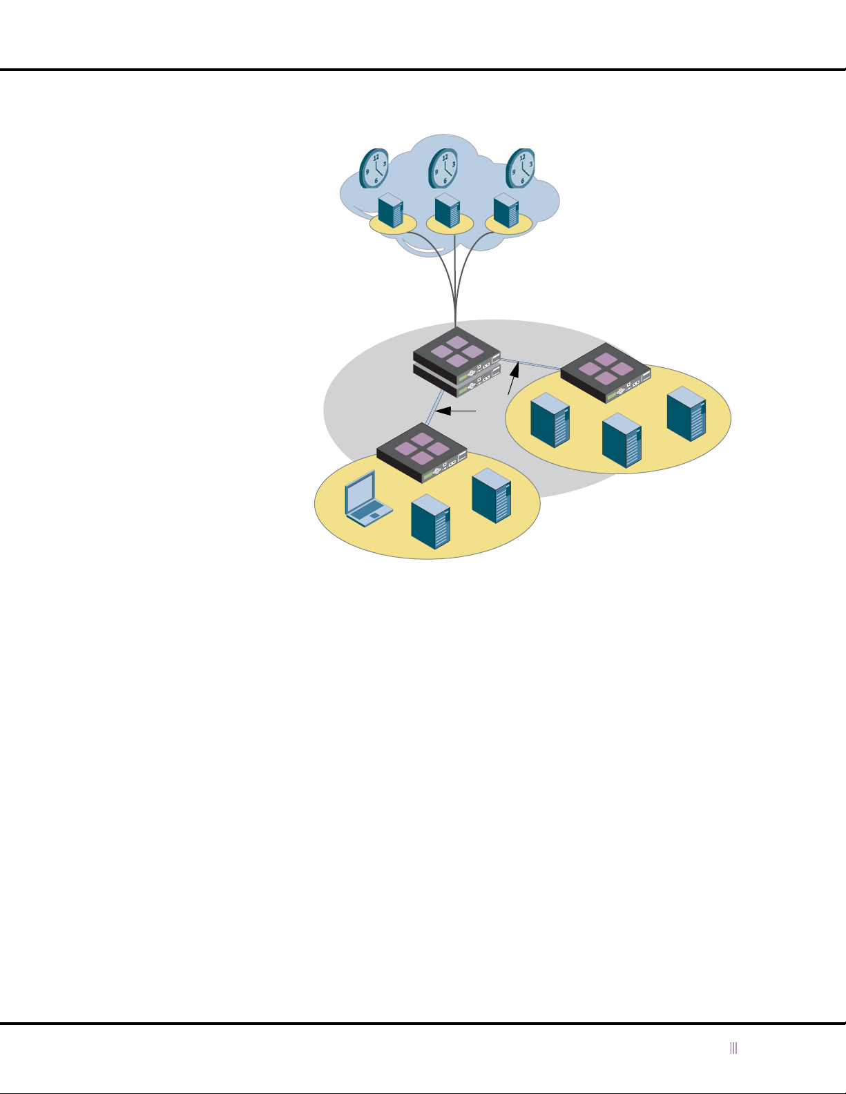
Figure 4.1 Infoblox Appliances as NTP Servers
Using NTP for Time Settings
Internet
Stratum-1 NTP Servers use reference
clocks to synchronize their time to
UTC (Universal Coordinated Time).
As an NTP client, the grid master
synchronizes its time with stratum-1
NTP servers. The grid master also
functions as a stratum-2 NTP server
to grid members. NTP messages
between the grid master and grid
members go through encrypted VPN
tunnels.
As NTP clients, the grid members
synchronize their clocks with the grid
master. The grid members also
function as stratum-3 NTP servers to
external devices on their networks.
Grid
Member
Grid Master
VPN
Tunnel
1 Network
Reference Clocks
Stratum-1 NTP Servers
Grid
Member
2 Network
Authenticating NTP
To prevent intruders from interfering with the time services on your network, you can authenticate communications
between an Infoblox device and a public NTP server, and between a device and external NTP clients. NTP
communications within the grid go through an encrypted VPN tunnel, so you do not have to enable authentication
between members in a grid.
NTP uses symmetric key cryptography, where the server and the client use the same algorithm and key to calculate
and verify a MAC (message authentication code). The MAC is a digital thumbprint of the message that the receiver
uses to verify the authenticity of a message.
As shown in
administrator of the NTP server. The server and the client must have the same key ID and data. Therefore, when you
configure the device as an NTP client and want to use authentication, you must obtain the key information from the
administrator of the external NTP server and enter the information on the device. When you configure an Infoblox
device as an NTP server, you must create a key and send the key information to clients in a secure manner. A key
consists of the following:
• Key Number: A positive integer that identifies the key.
• Key Type: Specifies the key format and the algorithm used to calculate the MAC (message authentication code)
of a message.
— M: The key is a 1-31 character ASCII string using MD5 (Message Digest).
— S: The key is a 64-bit hexadecimal number in DES (Data Encryption Standard) format. The high order 7 bits
Figure 4.2
, the NTP client administrator must first obtain the secret key information from the
of each octet form the 56-bit key, and the low order bit of each octet is given a value so that the octet
maintains odd parity. You must specify leading zeros so the key is exactly 16 hexadecimal digits long and
maintains odd parity.
NIOS 4.0 Infoblox Administrator Guide (Rev. E) 61
Page 62
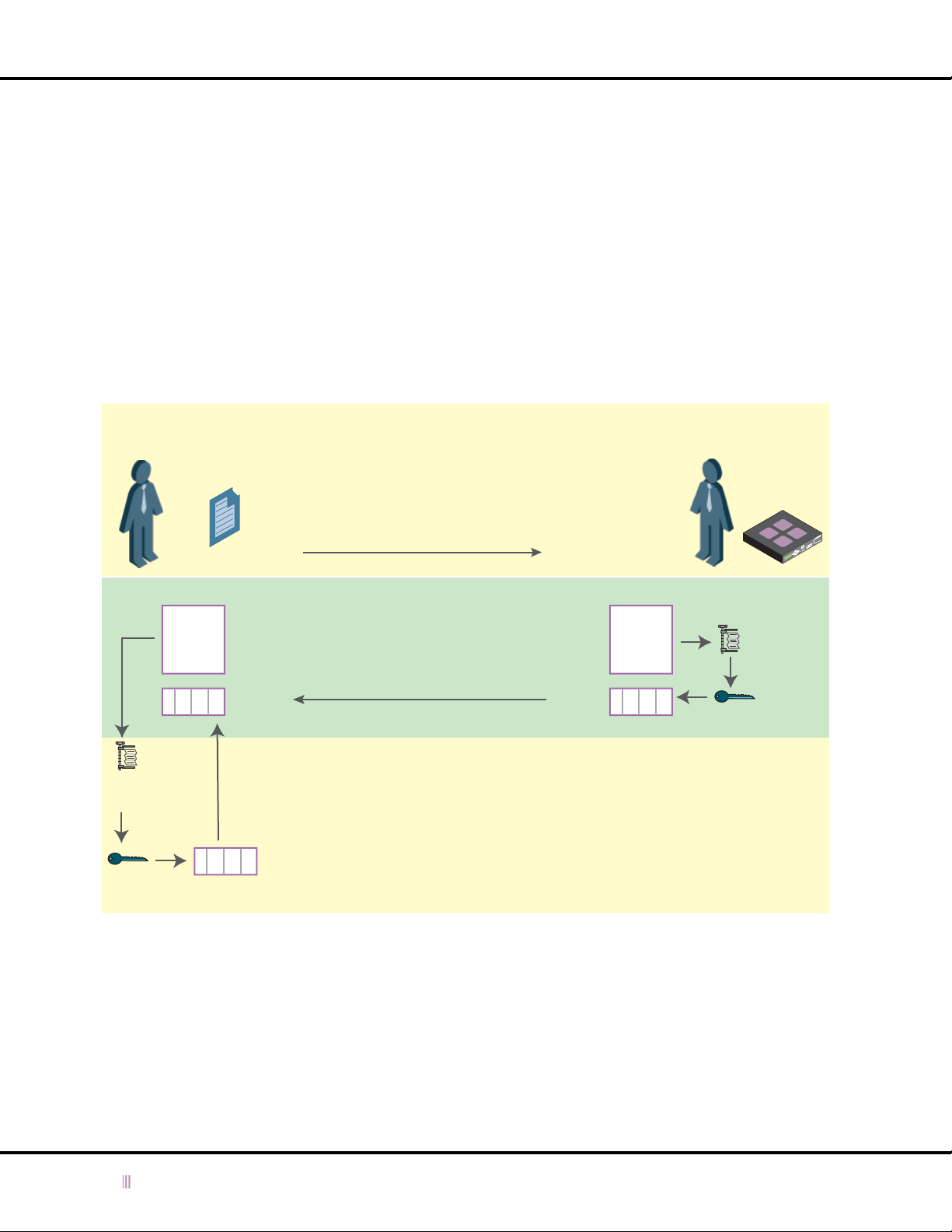
Chapter 4: Managing Device Operations
— A: The key is a DES key written as a 1-8 character ASCII string.
— N: The key is a 64-bit hexadecimal number in NTP format. It is the same as the S format, but the bits in each
octet have been rotated one bit right so the parity bit is in the high order bit of the octet. You must specify
leading zeros and odd parity must be maintained.
• Key String: The key data used to calculate the MAC. The format depends on the Key Type you select.
When the NTP client initiates a request for time services to the NTP server, it creates the MAC by using the agreed
upon algorithm to compress the message and then encrypts the compressed message (which is also called a
message digest) with the secret key. The client appends the MAC to the message it sends to the NTP server. When the
NTP server receives the message from the client, it performs the same procedure on the message — it compresses
the message it received, encrypts it with the secret key and generates the MAC. It then compares the MAC it created
with the MAC it received. If they match, the server continues to process and respond to the message. If the MACs do
not match, the receiver drops the message.
Figure 4.2 NTP Client Administrator Obtaining Secret Key from NTP Server Administrator
NTP Server
Administrator
Message
MAC
MD5 or DES
Message Digest
Encrypted with
Secret Key
Secret Key
Information
MAC
NTP server administrator sends the secret key
information to the NTP client administrator, who
adds the key to the NTP client.
When the NTP client sends a request for time
services to the NTP server, it uses the agreed
upon algorithm and secret key to create the MAC
(message authorization code). It then sends the
MAC and message to the NTP server.
NTP server uses the agreed upon
algorithm and secret key to create the
MAC. It compares this MAC with the MAC
it received. If they match, the server
responds to the request of the client for
time services. If the MACs do not match,
the server ignores the message from the
client.
NTP Client
Administrator
Message
+
MAC
NTP Client
MD5 or DES
Message Digest
Encrypted with
Secret Key
62 Infoblox Administrator Guide (Rev. E) NIOS 4.0
Page 63
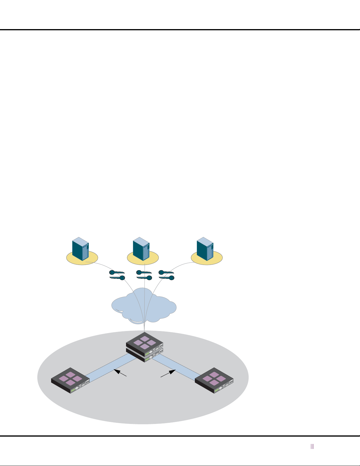
Using NTP for Time Settings
Infoblox Device as NTP Client
You can configure an independent device or the grid master in an ID grid as a n NTP client that synchronizes its system
clock time with an external NTP server.
When you enable an Infoblox device to function as an NTP client, you must specify at least one NTP server with which
the device can synchronize its clock. If you specify multiple NTP servers, you should specify servers that synchronize
their time with different reference clocks and that have different network paths. This increases stability and reduces
risk in case a server fails. For a list of public NTP servers, you can access www.ntp.org.
When you specify multiple NTP servers, the NTP daemon on the device determines the best source of time by
calculating round-trip time, network delay, and other factors that affect the accuracy of the time. NTP periodically
polls the servers and adjusts the time on the device until it matches the best source of time. If the difference between
the device and the server is less than five minutes, the device adjusts the time gradually until the clock time matches
the NTP server. If the difference in time is more than five minutes, the device immediately synchronizes its time to
match that of the NTP server.
To secure communications between an Infoblox device and an NTP server, you can authenticate communications
between the device and the server. When you configure authentication, you must obtain the key information from the
administrator of the NTP server and enter the key on the device. For more information, see
page 61.
For appliances in an ID grid, only the grid master can synchronize its clock with an external NTP server. When you
enable NTP on the grid master in an ID grid, the grid master automatically functions as an NTP server to the grid
members. A grid member can synchronize its time only with the grid master, and not with an external NTP server or
another grid member. Like all other grid communications, the grid master and its members send NTP messages
through an encrypted VPN tunnel.
Authenticating NTP
on
Figure 4.3 Grid Master as NTP Client
NTP Server 1 NTP Server 2 NTP Server 3
Secret Keys
Internet
The grid master uses three public NTP
servers to calibrate its clock to the correct
time. It uses symmetric key cryptography to
authenticate NTP messages.
The grid master serves time to the grid
members. All NTP communications with
the grid go through encrypted VPN tunnels.
Grid Master
VPN Tunnels
Grid Member
NIOS 4.0 Infoblox Administrator Guide (Rev. E) 63
Grid Member
Page 64

Chapter 4: Managing Device Operations
Following are the tasks to configure an independent device or a grid master as an NTP client:
•Enable NTP
• Specify one or more NTP servers
• Optionally, enable authentication between the device and the NTP server. For more information, see
Authenticating NTP Clients
on page 66.
Configuring an Infoblox Device as an NTP Client
In an ID grid, the grid master communicates directly with an external NTP server from which it receives its date and
time. The master then forwards the date and time to the other grid members. Likewise, in an independent HA pair,
th e active n ode commun icates dir ectly wi th a n extern al NTP ser ver. The p assiv e no de t hen synch ron izes it s clock with
the active node.
To configure an ID grid master or independent device or HA pair to synchronize its time with an external NTP server:
1. For an ID grid: From the ID Grid perspective, click + (for
Properties.
or
For an independent device or HA pair: From the ID Device perspective, click + (for
Service Properties.
2. In the
3. To define external NTP servers, click Add, enter the following information, and then click OK.
NTP Properties
— NTP Server Address: Type the IP address of an NTP server. You can see a list of NTP servers at ntp.isc.org.
— Enable Authentication: Select the check box to enable authentication of NTP communications between the
external NTP server and the Infoblox device (ID grid master, active node in an independent HA pair, or single
independent device).
editor, select Enable NTP.
id_grid
) -> + (for Services ) -> NTP -> Edit -> Service
hostname
) -> NTP -> Edit ->
Note: To prevent intruders from interfering with the time services on your network, you can authenticate
communications between a grid master and external NTP servers, and between grid members and
external NTP clients. NTP communications within the grid go through an encrypted VPN tunnel, so you do
not have to enable authentication between grid master and members.
— Authentication Key: Enter the authentication key string, which you have previously obtained from the
administrator of the NTP server.
or
Select Key: Click to open the
entered in the
4. Click the Save icon to save your changes.
5. Click the Restart Services icon if it flashes.
NTP Authentication Keys
Select NTP Authentication Key
section (see below), and then click OK.
dialog box, select a key that you previously
Entering an NTP Authentication Key
To add an NTP authentication key:
1. For an ID grid: From the ID Grid perspective, click + (for
Properties.
or
For an independent device or HA pair: From the ID Device perspective, click + (for
Service Properties.
2. In the
NTP Properties
editor, select Enable NTP.
id_grid
) -> + (for Services ) -> NTP -> Edit -> Service
hostname
) -> NTP -> Edit ->
64 Infoblox Administrator Guide (Rev. E) NIOS 4.0
Page 65

Using NTP for Time Settings
3. To enter a new key, click Add, enter the following information, and then click OK.
— Number: A positive integer that identifies a key.
— Key Type: Specifies the key format and the algorithm used to calculate the MAC (message authentication
code) of a message.
— MD5 in ASCII format (M): The key is a 1-31 character ASCII string using MD5 (Message Digest).
— DES in hex format (S): The key is a 64-bit hexadecimal number in DES (Data Encryption Standard)
format. The high order 7 bits of each octet form the 56-bit key, and the low order bit of each octet is
given a value so that the octet maintains odd parity. You must specify leading zeros so the key is
exactly 16 hexadecimal digits long and maintains odd parity.
— DES in ASCII format (A): The key is a DES key written as a 1-8 character ASCII string.
— DES in NTP format (N): The key is a 64-bit hexadecimal number in NTP format. It is the same as the S
format, but the bits in each octet have been rotated one bit right so the parity bit is in the high order bit
of the octet. You must specify leading zeros and odd parity must be maintained.
— String: The key data used to calculate the MAC. The format depends on the Key Type you select.
4. Click OK to close the
Note that if you entered a new key, the device checks if the key already exists in the key list. If the key does exist,
but either the key type or key string does not match, the device sends an error message.
5. Click the Save icon to save your changes.
6. Click the Restart Services icon if it flashes.
Add NTP server
dialog box.
Managing Keys
After you enter an authentication key, you can modify or delete it. Note that you cannot delete a key that is an NTP
server references. You must first delete all NTP servers that reference that key and then delete the key.
To delete a key from the list:
1. For an ID grid: From the ID Grid perspective, click + (for
Properties.
or
For an independent device or HA pair: From the ID Device perspective, click + (for
Service Properties.
2. In the
3. Click the Save icon to save your changes.
NTP Properties
click Delete.
editor, select the key you want to delete from the NTP Authentication Keys list, and then
id_grid
) -> + (for Services ) -> NTP -> Edit -> Service
hostname
) -> NTP -> Edit ->
NIOS 4.0 Infoblox Administrator Guide (Rev. E) 65
Page 66

Chapter 4: Managing Device Operations
Infoblox Device as NTP Server
After you enable NTP on an ID grid, the grid members—including the grid master—can function as NTP servers to
clients in different segments of the network. Similarly, after you enable NTP on an independent device or HA pair and
it synchronizes its time with an NTP server, you can configure it to function as an NTP server as well.
Access Control
The NTP access control list limits which clients can use an Infoblox device functioning as an NTP server. If you do not
use the access control list, then any client that has access to the device can use it as an NTP server. If you enter one
or more IP addresses, then only the clients you specify can access NTP services from that device.
To restrict access for an ID grid or for an independent device or HA pair:
1. For an ID grid: From the ID Grid perspective, click + (for
Properties.
or
For an independent device or HA pair: From the ID Device perspective, click + (for
Service Properties.
2. Click Add (for NTP Access Control), enter the following information, and then click OK.
—IP Address Option
— Address: To allow a client from a single IP address to access grid members functioning as NTP servers,
select this option and enter the IP address in Address field.
—or
— Network: To restrict access to grid members functioning as NTP servers to a subnet, select this option
and enter the network address in the Address field and choose an appropriate netmask from the
drop-down list.
—or
— Any: Select this option to allow access to grid members functioning as NTP servers from any address. If
you do not make any access restrictions, the grid members allow access from any address.
3. If necessary, click Move up and Move down to reorder the IP addresses in the list. When a device requests NTP
information from the Infoblox device, it tries to match the client’s IP address with IP addresses in the list,
beginning at the top of the list and continuing downward until it finds a match. If there is at least one item in the
NTP Access Control list and a client’s IP address does not match it, the Infoblox device ignores its NTP requests.
4. Click the Save icon to save your changes.
id_grid
) -> + (for Services ) -> NTP -> Edit -> Service
hostname
) -> NTP -> Edit ->
Authenticating NTP Clients
You can enable authentication between an Infoblox device functioning as an NTP server and its NTP clients. When you
enable authentication, you must specify the keys that the device and its clients must use for authentication. In a grid,
you can enter NTP authentication keys at the grid level so that all the members can use them to authenticate their
clients. You can also enter keys at the member level, if you want that member to use different keys from those set at
the grid level. After you enter the keys, you can download the key file and distribute the file to the NTP clients.
To authenticate NTP traffic between an Infoblox device and NTP clients:
1. Define one or more keys at the grid or member level, or for an independent device or HA pair.
2. Distribute the key to the NTP clients.
To add a new key for an ID grid or for an independent device or HA pair:
1. For an ID grid: From the ID Grid perspective, click + (for
Properties.
or
For an independent device or HA pair: From the ID Device perspective, click + (for
Service Properties.
66 Infoblox Administrator Guide (Rev. E) NIOS 4.0
id_grid
) -> + (for Services ) -> NTP -> Edit -> Service
hostname
) -> NTP -> Edit ->
Page 67

Using NTP for Time Settings
2. Click Add (for NTP Authentication Keys), enter the following information, and then click OK.
— Number: A positive integer that identifies a key.
— Key Type: Specifies the key format and the algorithm used to calculate the MAC (message authentication
code) of a message.
— MD5 in ASCII format (M): The key is a 1-31 character ASCII string using MD5 (Message Digest).
— DES in hex format (S): The key is a 64-bit hexadecimal number in DES (Data Encryption Standard)
format. The high order 7 bits of each octet form the 56-bit key, and the low order bit of each octet is
given a value so that the octet maintains odd parity. You must specify leading zeros so the key is
exactly 16 hexadecimal digits long and maintains odd parity.
— DES in ASCII format (A): The key is a DES key written as a 1-8 character ASCII string.
— DES in NTP format (N): The key is a 64-bit hexadecimal number in NTP format. It is the same as the S
format, but the bits in each octet have been rotated one bit right so the parity bit is in the high order bit
of the octet. You must specify leading zeros and odd parity must be maintained.
— String: The key data used to calculate the MAC. The format depends on the Key Type you select.
3. Click the Save icon to save your changes.
You can download the key file, which is usually called ntp.keys, and distribute the file to the NTP clients. To download
a key file at the grid or independent device level:
To copy an NTP authentication key for distribution to NTP clients:
1. For an ID grid: From the ID Grid perspective, click + (for
id_grid
) -> + (for Services ) -> NTP -> Edit -> Service
Properties.
or
For an independent device or HA pair: From the ID Device perspective, click + (for
hostname
) -> NTP -> Edit ->
Service Properties.
2. Choose the key in the NTP Authentication Keys list, and then click Modify.
3. Note the key number and type, and select the contents of the String field.
4. Paste the key string in a text file and include the key number and type (M, S, A, or N) in the file.
5. Distribute this to the NTP clients using a secure transport.
NIOS 4.0 Infoblox Administrator Guide (Rev. E) 67
Page 68
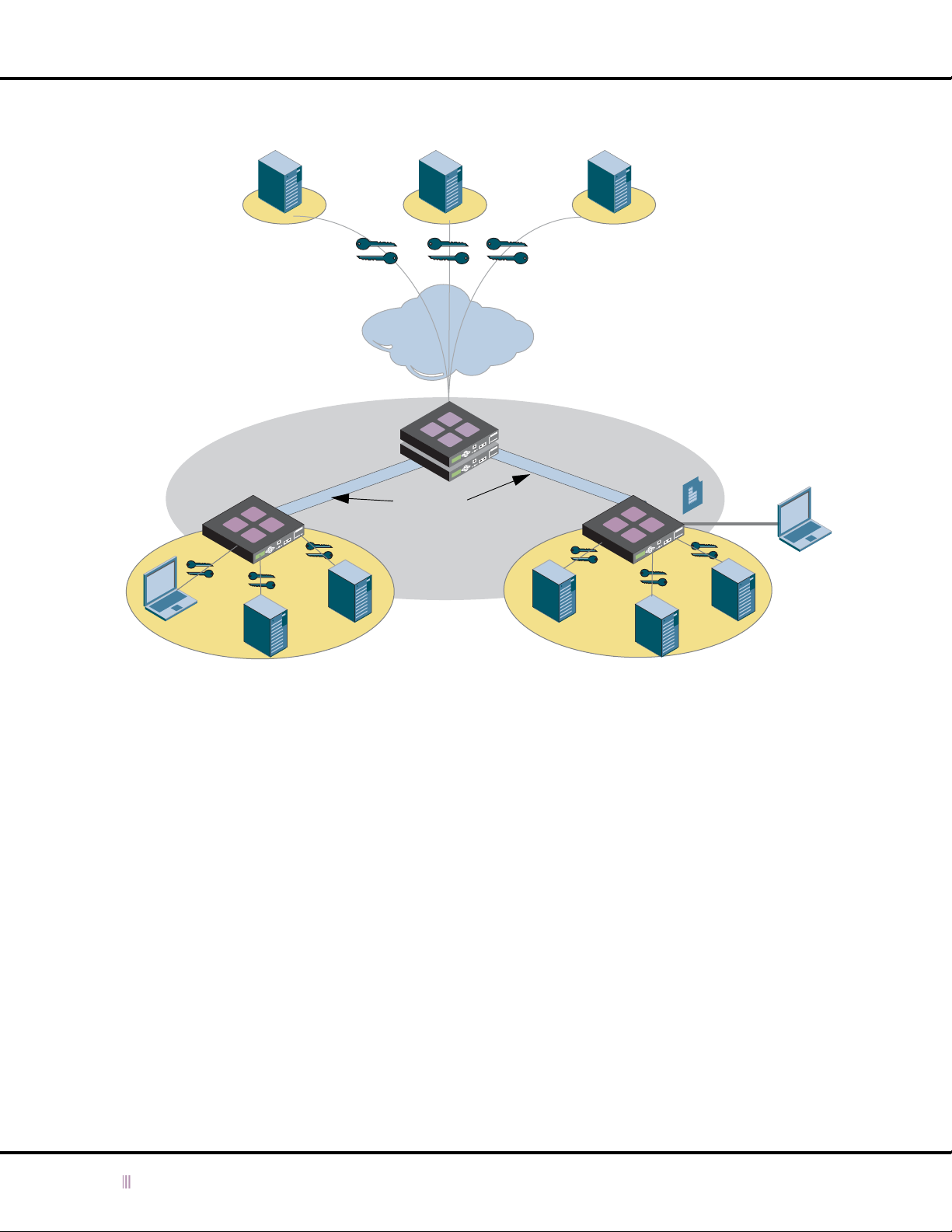
Chapter 4: Managing Device Operations
Figure 4.4 Grid Members as NTP Servers
NTP Server 1 NTP Server 2 NTP Server 3
The grid master uses three public NTP
servers to calibrate its clock to the
correct time. It uses symmetric key
cryptography to secure NTP messages.
The grid master serves time to the grid
members. All NTP communications
with the grid go through the encrypted
VPN tunnels.
Internet
Secret Keys
The grid members serve time to devices on their
networks. Each member uses symmetric key
encryption to secure NTP messages. Each
member also has an access control list that
defines which devices can access the time
services. When a client that is not on the list tries
to access a device functioning as an NTP
server, the device ignores the message.
Grid Master
Access Control List
Grid Member
3 Network 2 Network
VPN
Tunnels
Grid Member
X
Configuring an Infoblox Device as an NTP Server
You can configure an ID grid member—including the grid master—or an independent device or HA pair to function as
an NTP server.
To configure an ID grid member to be an NTP server:
1. From the ID Grid perspective, click + (for
Properties.
2. In the
Member NTP Properties
editor, select the Override ID Grid NTP authentication setting check box to enter
NTP authentication keys at the member level instead of using grid-level keys. The member uses these keys when
acting as an NTP server and authenticates requests from NTP clients. Clear the check box to use the grid-level
authentication keys.
3. Click Add (for NTP Authentication Keys), enter the following information, and then click OK.
— Number: A positive integer that identifies the key.
— Key Type: Specifies the key format and the algorithm used to calculate the MAC (message authentication
code) of a message.
— MD5 in ASCII format (M): The key is a 1-31 character ASCII string using MD5 (Message Digest).
— DES in hex format (S): The key is a 64-bit hexadecimal number in DES (Data Encryption Standard)
format. The high order 7 bits of each octet form the 56-bit key, and the low order bit of each octet is
given a value so that the octet maintains odd parity. You must specify leading zeros so the key is
exactly 16 hexadecimal digits long and maintains odd parity.
id_grid
) -> + (for Member ) -> + (for
member
) -> NTP -> Edit -> Service
68 Infoblox Administrator Guide (Rev. E) NIOS 4.0
Page 69

Using NTP for Time Settings
— DES in ASCII format (A): The key is a DES key written as a 1-8 character ASCII string.
— DES in NTP format (N): The key is a 64-bit hexadecimal number in NTP format. It is the same as the S
format, but the bits in each octet have been rotated one bit right so the parity bit is in the high order bit
of the octet. You must specify leading zeros and odd parity must be maintained.
— String: The key data used to calculate the MAC. The format depends on the Key Type you select.
4. Click the Save icon to save your changes.
To configure an independent device or HA pair to be an NTP server:
1. From the ID Device perspective, click + (for
2. In the
3. Click the Save icon to save your changes.
ID Device NTP Properties
— Enable external NTP: Select the check box and configure external NTP servers. Before a device or HA pair
can be an NTP server, it must first be an NTP client. For more information, see
on page 63.
— Enable this member as an NTP server: Select the check box.
Note: You can also configure the Infoblox device to control access to the NTP server and authenticate NTP
clients’ requests. See
editor, enter the following:
Access Control
hostname
on page 66 and
) -> NTP -> Edit -> Service Properties.
Infoblox Device as NTP Client
Authenticating NTP Clients
on page 66.
NIOS 4.0 Infoblox Administrator Guide (Rev. E) 69
Page 70

Chapter 4: Managing Device Operations
Managing Security Operations
The procedures in this section apply to both independent and ID grid installations.
You can specify these security operations:
•
Enabling Support Access
•
Enabling Remote Console Access
•
Permanently Disabling Remote Console and Support Access
•
Restricting HTTP Access
•
Enabling HTTP Redirection
•
Modifying GUI Session Timeout Settings
•
Disabling the LCD Input Buttons
•
Modifying Security for an ID Grid Member
Enabling Support Access
Infoblox Technical Support might need access to your Infoblox device to troubleshoot problems. This function
enables an SSH (Secure Shell) daemon that only Infoblox Technical Support can access. If you have any questions,
contact Infoblox Technical Support at
To enable Infoblox Technical Support access:
1. From the ID Grid perspective, click
or
From the ID Device perspective, click
2. In the
3. Click the Save icon.
ID Grid
(or
ID Device
on page 70
on page 70
on page 71
on page 71
on page 72
on page 72
on page 72
on page 73
[email protected]. By default, this option is disabled.
id_grid
-> Edit -> Grid Properties.
hostname
) editor, click Security, and then select Enable Support access.
-> Edit -> ID Device Properties.
Note: When configuring ID grid members, you can selectively override the grid-level Support access setting at the
member level.
Enabling Remote Console Access
This function makes it possible for a superuser admin to access the Infoblox CLI from a remote location using an SSH
(Secure Shell) v2 client. The management system must have an SSH v2 client to use this function. After opening a
remote console connection using an SSH client, log in using a superuser name and password. By default, this option
is disabled.
To enable remote console access:
1. From the ID Grid perspective, click
or
From the ID Device perspective, click
2. In the
3. Click the Save icon.
Note: When configuring ID grid members, you can selectively override the grid-level remote console access setting
ID Grid
at the member level.
(or
ID Device
) editor, click Security, and then select Enable remote console access.
id_grid
-> Edit -> Grid Properties.
hostname
-> Edit -> ID Device Properties.
70 Infoblox Administrator Guide (Rev. E) NIOS 4.0
Page 71

Managing Security Operations
Permanently Disabling Remote Console and Support Access
You can permanently disable remote console (Secure Shell v2) access for device administration and for Infoblox
Technical Support to perform remote troubleshooting. Disabling this type of access might be required in a
high-security environment.
WARNING: After permanently disabling remote console and support access, you cannot re-enable them! Not
even resetting a device to its factory default settings can re-enable them.
To permanently disable remote console access and Infoblox Technical Support access:
1. From the ID Grid perspective, click
or
From the ID Device perspective, click
2. In the
3. Click the Save icon.
ID Grid
(or
support access.
ID Device
) editor, click Security, and then select Permanently disable remote console and
id_grid
-> Edit -> Grid Properties.
hostname
-> Edit -> ID Device Properties.
Restricting HTTP Access
You can specify the IP addresses from which administrators are allowed to access the Infoblox device.
Caution: If you specify an address or network other than the one from which you are currently accessing the device,
when you save your configuration, you will lose your administrative session and be unable to reconnect.
To restrict HTTP access to the Infoblox ID Manager GUI to select addresses:
1. From the ID Grid perspective, click
or
From the ID Device perspective, click
2. To set restrictions on the IP addresses from which administrators can access the Infoblox device, select Enable
HTTP access restrictions in the
—Address Type:
— Address: To allow administrative access to the ID Device Manager GUI from a single IP address, select
this option and enter the IP address in the Address field. Note that if you specify an address other than
the one from which you are currently accessing the device, when you save your configuration, you will
lose your administrative session and be unable to reconnect.
— Network: To restrict administrative access to the ID Device Manager GUI to a subnet, select this option
and enter the network address in the Address field and choose an appropriate netmask from the
drop-down list. Note that if you specify a subnet other than the one from which you are currently
accessing the device, when you save your configuration, you will lose your administrative session and
be unable to reconnect.
— Any: Select this option to allow access from any address. When you do not make any access
restrictions, the Infoblox device allows access from any address.
3. If necessary, click Move up and Move down to reorder the IP addresses in the list. When a device makes a
connection request to the Infoblox device, the device tries to match the client’s IP address with IP addresses in
the list, beginning at the top of the list and continuing downward until it finds a match. If there is at least one
item in the HTTP Access Control list and a client’s IP address does not match it, the Infoblox device ignores its
requests.
4. Click the Save icon to save your changes.
The application restarts and your management session terminates.
5. From the JWS (Java Web Start) login prompt, log back in to the device.
id_grid
hostname
Security
-> Edit -> Grid Properties.
-> Edit -> ID Device Properties.
section, click Add, enter the following, and then click OK:
NIOS 4.0 Infoblox Administrator Guide (Rev. E) 71
Page 72

Chapter 4: Managing Device Operations
Enabling HTTP Redirection
You can enable the Infoblox device to redirect administrative connection requests using HTTP to the secure HTTPS
protocol. When you disable redirection, the Infoblox device ignores any administrative connection requests not using
HTTPS. By default, the Infoblox device does not redirect HTTP connection requests to HTTPS.
To enable redirection:
1. From the ID Grid perspective, click
or
From the ID Device perspective, click
2. In the
3. Click the Save icon to save your changes.
4. From the JWS (Java Web Start) login prompt, log back in to the device.
ID Grid
The application restarts and your management session terminates.
(or
ID Device
) editor, click Security, and then select Auto-Redirect HTTP -> HTTPS.
id_grid
-> Edit -> Grid Properties.
hostname
-> Edit -> ID Device Properties.
Modifying GUI Session Timeout Settings
You can set the length of idle time before an administrative session to the Infoblox ID Manager GUI times out. The
default timeout value is 600 seconds (5 minutes).
Note: If you change Session Timeout settings, you must close your browser window and log back in.
To modify session timeout settings:
1. From the ID Grid perspective, click
or
From the ID Device perspective, click
2. In the
3. Click the Save icon to save your changes.
4. From the JWS (Java Web Start) login prompt, log back in to the device.
ID Grid
(or
ID Device
(one minute – one year) in the Session Timeout field. The default session timeout is 600 seconds (five minutes).
The application restarts and your management session terminates.
) editor, click Security, and then enter a number between 60 and 31536000 seconds
id_grid
-> Edit -> Grid Properties.
hostname
-> Edit -> ID Device Properties.
Disabling the LCD Input Buttons
By default, the LCD input function is enabled, which allows you to use the LCD buttons on the front panel of an
Infoblox device to change the IP address settings of the LAN port. You can disable this function if the device is in a
location where you cannot restrict access exclusively to Infoblox device administrators and you do not want anyone
to be able to make changes through the LCD.
To disable LCD input to the device:
1. From the ID Grid perspective, click
or
From the ID Device perspective, click
2. In the
3. Click the Save icon to save your changes.
ID Grid
(or
ID Device
) editor, click Security, and then clear Enable LCD input.
id_grid
-> Edit -> Grid Properties.
hostname
-> Edit -> ID Device Properties.
72 Infoblox Administrator Guide (Rev. E) NIOS 4.0
Page 73

Managing Security Operations
Modifying Security for an ID Grid Member
You can override a number of grid-level security settings at the member level.
Note: You can only manage session timeout settings, HTTPS redirection, HTTP access, audit log rolling, password
length, and login banner text at the grid level.
To enable support access for a member:
1. From the ID Grid perspective, click + (for
2. In the
3. Click the Save icon to save your changes.
ID Grid
(or
ID Device
— To override grid-level settings for remote console access, select the Override ID grid remote console access
setting check box, and then select or clear the Remote console access enabled check box.
— To override grid-level settings for Infoblox Technical Support access, select the Override ID grid support
access setting check box, and then select or clear the Enable support access check box.
— To override grid-level LCD input settings, select the Override ID grid support LCD input setting check box,
and then select or clear the Enable LCD input check box.
) editor, click Security, and then enter the following:
id_grid
) - > + (for Member ) ->
member
-> Edit -> Member Properties.
NIOS 4.0 Infoblox Administrator Guide (Rev. E) 73
Page 74
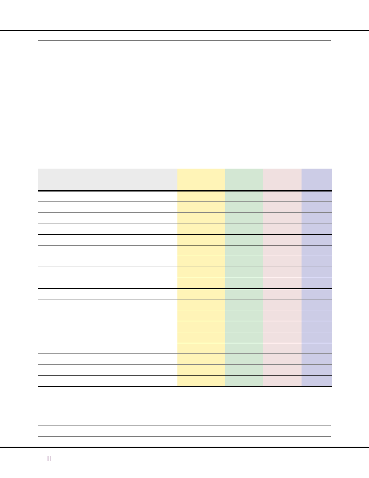
Chapter 4: Managing Device Operations
Ethernet Port Usage
The three ethernet ports on an Infoblox device perform different functions, which vary depending on deployment and
configuration choices. The three ethernet ports that transmit and receive traffic to the Infoblox device are as follows:
• LAN port – This is the default port for single independent appliances, single grid members, and passive nodes
in HA pairs. All deployments use the LAN port for management services if the MGMT port is disabled. On
Infoblox-500, -1000, and -1200 appliances, this port is labeled LAN. On Infoblox-550, -1050, -1550, and -1552
appliances, it is labeled LAN1. (The LAN2 port is reserved for future use.)
• HA port – This is the default port for the active grid master node and the active node in an independent HA pair.
• MGMT port – If the MGMT port is enabled, the Infoblox device uses it for many types of management services
(see
Table 4.2
Table 4.1
displays the type of traffic per port for both ID grid and independent deployments. For a more detailed list
of the different types of traffic, see
Table 4.1 Device Roles and Configuration, Communication Types, and Port Usage
on page 75 for specific types).
Table 4.2
on page 75.
Device Role HA Pair HA Status MGMT Port
HA Grid Master Yes Active Disabled VIP on HA VIP on HA LAN VIP on HA
HA Grid Master Yes Passive Disabled LAN – LAN –
Single Grid Master No – Disabled LAN LAN LAN LAN
HA Grid Member Yes Active Disabled LAN VIP on HA LAN –
HA Grid Member Yes Passive Disabled LAN – LAN –
Single Grid Member No – Disabled LAN LAN LAN –
Independent HA Pair Yes Active Disabled VIP on HA VIP on HA LAN VIP on HA
Independent HA Pair Yes Passive Disabled LAN – LAN –
Single Independent No – Disabled – LAN LAN LAN
HA Grid Master Yes Active Enabled VIP on HA VIP on HA MGMT MGMT
HA Grid Master Yes Passive Enabled LAN – MGMT –
Single Grid Master No – Enabled LAN LAN or MGMT MGMT MGMT
HA Grid Member Yes Active Enabled LAN or MGMT VIP on HA MGMT –
HA Grid Member Yes Passive Enabled LAN or MGMT – MGMT –
Single Grid Member No – Enabled LAN or MGMT LAN or MGMT MGMT –
Database
Synchronization
Network
Identity
Services
Management
Services
GUI
Access
Independent HA Pair Yes Active Enabled VIP on HA VIP on HA MGMT MGMT
Independent HA Pair Yes Passive Enabled LAN – MGMT –
Single Independent No – Enabled – LAN or MGMT MGMT MGMT
To see the service port numbers and the source and destination locations for traffic that can go to and from an
Infoblox device, see
Table 4.2
. This information is particularly useful for firewall administrators so that they can set
policies to allow traffic to pass through the firewall as required.
Note: The colors in both tables represent a particular type of traffic and correlate with each other.
74 Infoblox Administrator Guide (Rev. E) NIOS 4.0
Page 75

Table 4.2 Sources and Destinations for Services
Ethernet Port Usage
Service SRC IP DST IP Proto
Key
Exchange
LAN on grid
member
VIP on HA grid
master, or LAN or
17 UDP 2114 2114 Initial key exchange for
single master
VPN LAN on grid
member
VIP on HA grid
master, or LAN or
17 UDP 1194 or
single master
DHCP Client LAN, VIP, or
17 UDP 68 67 Required for DHCP service
broadcast on
Infoblox device
DHCP LAN or VIP on
Client 17 UDP 67 68 Required for DHCP service
Infoblox device
DHCP
Failover
DHCP
Failover
LAN or VIP on
Infoblox DHCP
failover peer
VIP on HA grid
master or LAN on
single master
LAN or VIP on
Infoblox DHCP
failover peer
LAN or VIP on
grid member in a
DHCP failover
6 TCP 519 519 Required for DHCP failover
6 TCP 1024 ->
pair
SRC
Port
5002,
or 1024
->
63999
65535
DST
Port
Notes
establishing VPN tunnels
Required for Keystone
1194 or
5002,
or 1024
->
63999
Default VPN port 1194 for ID
grids with new DNSone 3.2
installations and 5002 for
grids upgraded to DNSone
3.2; the port number is
configurable
Required for Keystone
7911 Informs functioning grid
member in a DHCP failover
pair that its partner is down
Required for DHCP failover
DDNS
Updates
DNS
Transfers
LAN or VIP LAN or VIP 17 UDP 1024 ->
65535
LAN, VIP, or
MGMT, or client
LAN, VIP, or
MGMT
6 TCP 53, or
1024 ->
65535
DNS
Queries
Client LAN, VIP, or
broadcast on
Infoblox device
17 UDP 53, or
1024 ->
65535
NTP NTP client VIP or LAN 6 TCP 1024 ->
65535
RADIUS
Authenti-
NAS (network
access server)
LAN or VIP 17 UDP 1024 –
65535
cation
53 Required for DHCP to send
DNS dynamic updates
53 For DNS zone transfers, large
client queries, and for ID grid
members to communicate
with external name servers
Required for DNS
53 For DNS queries
Required for DNS
123 Required if the Infoblox
device is an NTP server
1812 For proxying RADIUS
Authentication-Requests.
The default destination port
number is 1812, and can be
changed to 1024 – 63997.
NIOS 4.0 Infoblox Administrator Guide (Rev. E) 75
Page 76

Chapter 4: Managing Device Operations
Service SRC IP DST IP Proto
RADIUS
Accounting
RADIUS
Proxy
ICMP Dst
Port
Unreachable
ICMP Echo
Reply
ICMP Echo
Request
NAS (network
LAN or VIP 17 UDP 1024 –
access server)
LAN or VIP RADIUS home
server
VIP, LAN, or
MGMT, or
LAN or UNIXbased client
UNIX-based
client
VIP, LAN, or
MGMT, or client
VIP, LAN, or
MGMT, or client
VIP, LAN, or
MGMT, or client
VIP, LAN, or
MGMT, or client
17 UDP 1814 1024 ->
1 ICMP
Type 3
1 ICMP
Type 0
1 ICMP
Type 8
SRC
Port
DST
Port
Notes
1813 For proxying RADIUS
65535
Accounting-Requests. The
default destination port
number is 1813, and can be
changed to 1024 – 63998.
Required to proxy requests
63997
(auth),
or 1024
->
63998
(acct)
from RADIUS clients to
servers. The default source
port number is 1814, and
although it is not
configurable, it is always two
greater than the port number
for RADIUS authentication.
– – Required to respond to the
UNIX-based traceroute tool
to determine if a destination
has been reached
– – Required for response from
ICMP echo request (ping)
– – Required to send pings and
respond to the Windows-
based traceroute tool
ICMP TTL
Exceeded
Gateway device
(router or
Windows client 1 ICMP
Type 11
– – Gateway sends an ICMP TTL
firewall)
NTP LAN on active
node of ID grid
NTP server 6 TCP 1024 ->
65535
master or LAN of
independent
device
SMTP LAN or VIP Mail server 6 TCP 1024 ->
65535
SNMP NMS (network
management
VIP, LAN, or
MGMT
17 UDP 1024 ->
65535
system) server
SNMP Traps VIP on ID grid
master or HA
NMS server 17 UDP 1024 ->
65535
pair, LAN or
MGMT of
independent
device
exceeded message to a
Windows client, which then
records router hops along a
data path
123 Required to synchronize
Keystone, TSIG authentication, and DHCP failover
Optional for synchronizing
logs among multiple devices
25 Required if SMTP alerts are
enabled
161 Required for SNMP
management
162 Required for SNMP trap
management
76 Infoblox Administrator Guide (Rev. E) NIOS 4.0
Page 77

Ethernet Port Usage
Service SRC IP DST IP Proto
SSHv2 Client LAN, VIP, or
MGMT on
Infoblox device
Syslog LAN or MGMT of
Infoblox device
Traceroute LAN or UNIX-
based device
TFTP Data LAN or MGMT TFTP server 17 UDP 1024 ->
HTTP Management
System
HTTPS/
SSL
Management
System
syslog server 17 UDP 1024 ->
VIP, LAN, or
MGMT, or client
VIP, LAN, or
MGMT
VIP, LAN, or
MGMT
6 TCP 1024 ->
17 UDP 1024 ->
6 TCP 1024 ->
6 TCP 1024 ->
SRC
Port
65535
65535
65535
65535
65535
65535
DST
Port
22 Administrators can make an
514 Required for remote syslog
33000
->
65535
69,
then
1024 ->
63999
80 Required if the HTTP-redirect
443 Required for administration
Notes
SSHv2 connection to the
LAN, VIP, or MGMT port
Optional for management
logging
Infoblox device responds
with ICMP type code 3 (port
unreachable)
For contacting a TFTP server
during database and
configuration backup and
restore operations
option is set on the ID grid
properties security page
through the GUI
Modifying Ethernet Port Settings
By default, the Infoblox device automatically negotiates the optimal connection speed and transmission type (full or
half duplex) on the physical links between the 10/100Base-T and 10/100/1000Base-T ports on the Infoblox device
and the ethernet ports on a connecting switch. It is usually unnecessary to change the default auto-negotiation
setting; however, you can manually configure connection settings for a port if necessary.
Occasionally, for example, even though both the Infoblox device and the connecting switch support 1000-Mbps
(megabits per second) full-duplex connections, they might fail to auto-negotiate that speed and type, and instead
connect at lower speeds of either 100 or 10 Mbps using potentially mismatched full- and half-duplex transmissions.
If this occurs, first determine if there is a firmware upgrade available for the switch. If so, apply the firmware upgrade
and test the connection. If that does not resolve the issue, manually set the ports on the Infoblox device and on the
switch to make 1000-Mbps full-duplex connections.
To change ethernet port settings:
1. From the ID Grid perspective, click + (for
or
From the ID Device perspective, click
Note: You must enable the MGMT port before modifying its port settings. See
2. In the
3. Click the Save icon to save your changes.
ID Grid Member
— Use Automatic [ LAN | HA | MGMT ] Port Settings: Clear check box.
—[ LAN | HA | MGMT ] Speed: Choose the connection speed that you want the port to use.
—[ LAN | HA | MGMT ] Duplex: Choose Full for concurrent bidirectional data transmission or Half for data
transmission in one direction at a time.
or
ID Device
id_grid
) - > + (for Member ) ->
hostname
editor, click LAN/HA Ports or MGMT Port, and then enter the following:
-> Edit -> ID Device Properties.
member
-> Edit -> Member Properties.
Using the MGMT Port
on page 78.
Note: The port settings on the connecting switch must be identical to those you set on the Infoblox device.
NIOS 4.0 Infoblox Administrator Guide (Rev. E) 77
Page 78

Chapter 4: Managing Device Operations
Using the MGMT Port
The MGMT (Management) port is a 10/100Base-T ethernet connector on the front panel of an Infoblox-500, -1000,
and -1200 appliance and a 10/100/1000Base-T ethernet connector on the front panel of an Infoblox-550, -1050,
-1550, and -1552 appliance. It allows you to isolate the following types of traffic from other types of traffic on the LAN
and HA ports:
•
Device Management
•
ID Grid Communications
•
DNS Services
For information about what types of traffic qualify as device management, ID grid communications, and DNS services,
see
Table 4.2
Note: The MGMT port currently does not support DHCP, NTP, NAT, RADIUS proxying, or TFTP.
Some Infoblox device deployment scenarios support more than one concurrent use of the MGMT port. The following
table depicts MGMT port uses for various device configurations.
Table 4.3 Supported MGMT Port Uses for Various Device Configurations
on page 75.
(See page 79.)
(See page 81.)
(See page 84.)
Device
Configuration
Single Independent
Device
Independent HA Pair
ID Grid Master
ID Grid Master
Candidate
HA Grid Member
Single Grid Member
* Although you manage all grid members through the grid master, if you enable the MGMT port on common grid
members, they can send syslog events, SNMP traps, and e-mail notifications, and receive SSH connections on that
port.
Infoblox does not support MGMT port usage for some device configurations (indicated by the symbol
in
Table 4.3
that a VIP interface on the HA port provides for ID grid communications. Similarly, DNS servers in an HA pair need that
redundancy to answer DNS queries. Because the MGMT port does not support a VIP and thus cannot provide
redundancy, grid masters (and potential grid masters) do not support ID grid communications on the MGMT port, and
Infoblox devices in an HA pair do not support DNS services on the MGMT port.
The MGMT port is not enabled by default. By default, an Infoblox device uses the LAN port (and HA port when
deployed in an HA pair). You must log in using a superuser account to enable and configure the MGMT port. You can
enable the MGMT port through the Infoblox ID Manager GUI (as explained in the following sections) or through a
console connection with the following command:
) because it cannot provide the redundancy through the use of a VIP. A grid master needs the redundancy
Device
Management
*
*
ID Grid
Communications
Not Applicable
Not Applicable
DNS
Services
set interface mgmt speed auto duplex none
Note: For information about connecting ethernet cables to the MGMT port, refer to
page 371.
78 Infoblox Administrator Guide (Rev. E) NIOS 4.0
Cabling for the MGMT Port
on
Page 79
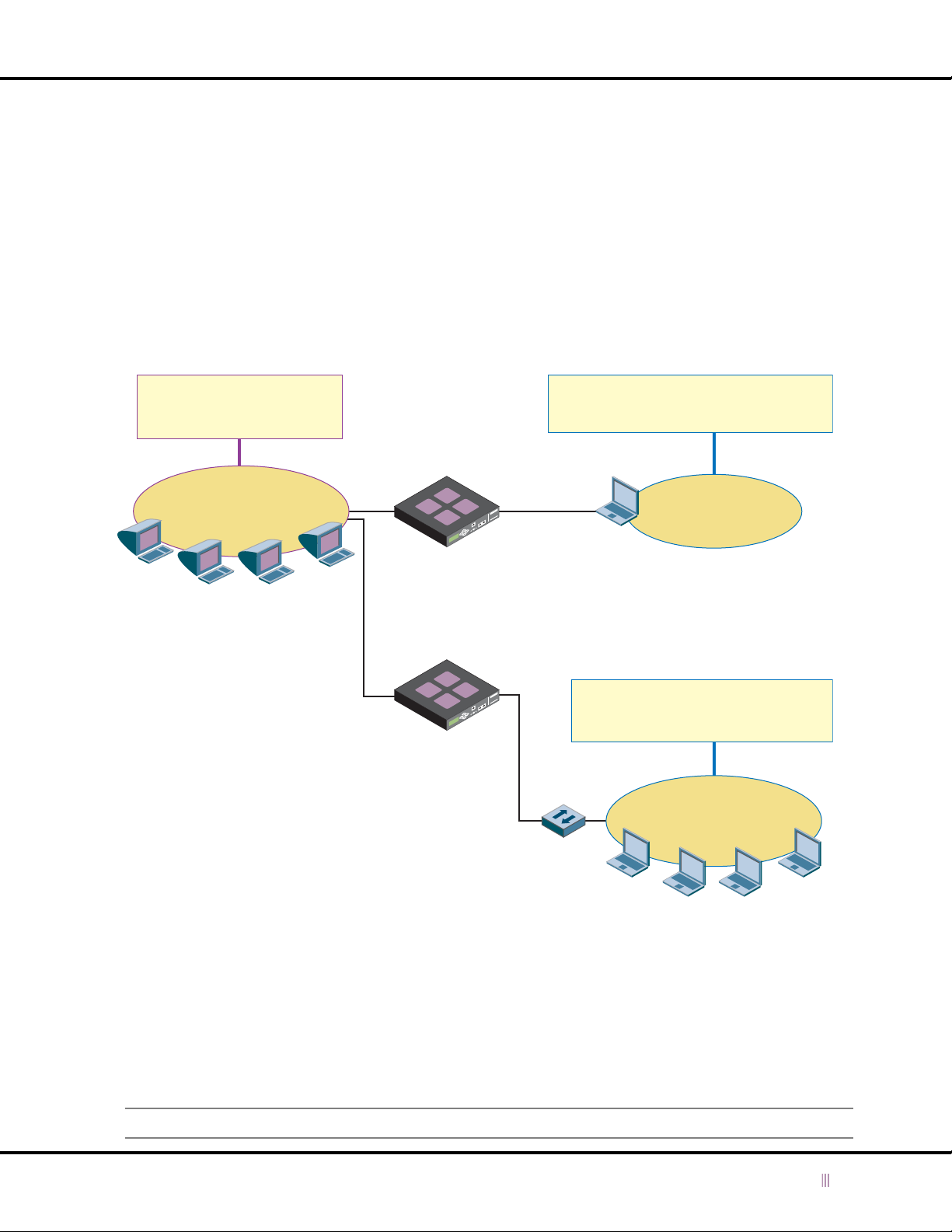
Using the MGMT Port
Device Management
You can restrict administrative access to an Infoblox device by connecting the MGMT port to a subnet containing only
management systems. This approach ensures that only devices on that subnet can access the Infoblox ID Manager
GUI and receive device management communications such as syslog events, SNMP traps, and e-mail notifications
from the device.
If you are the only administrator, you can connect your management system directly to the MGMT port. If there are
several administrators, you can define a small subnet—such as 10.1.1.0/29, which provides six host IP addresses
(10.1.1.1–10.1.1.7) plus the network address 10.1.1.0 and the broadcast address 10.1.1.8—and connect to the
Infoblox device though a dedicated switch; that is, a switch that is not connected to the rest of the network. See
Figure 4.5
services. Note that the LAN port is on a different subnet from the MGMT port.
Figure 4.5 Device Management from One or More Management Systems
, which shows how an independent device separates device management traffic from network protocol
The Infoblox device serves
DNS and DHCP to the public
network through the LAN port.
LAN
Public Network
1.1.1.0/24
DNS and DHCP Services
DNS and DHCP Clients
Note:
Because the two private networks are
used solely for device management and
are completely isolated from the rest of
the network—and therefore from each
other—their address space can overlap
without causing any routing issues
1.1.1.5
LAN
1.1.1.6
Infoblox
Device-1
Infoblox
Device -2
Ethernet
MGMT
10.1.1.1
MGMT
10.1.1.1
Cable
A single management system connects
directly to the MGMT port of the Infoblox
device through an ethernet cable.
Private Network
10.1.1.0/30
Ethernet
Cable
Several management systems connect
to the MGMT port of the Infoblox device
through a dedicated switch.
Dedicated
Switch
Device Management
Private Network
10.1.1.0/29
Device Management
Management Systems
10.1.1.2 - 10.1.1.5
Si mila rly, you can res tric t mana gem ent ac cess to a n ID gr id mas ter to on ly tho se de vice s co nne cted to the M GMT p orts
of the active and passive nodes of the ID grid master.
To enable the MGMT port on an independent device or ID grid master for device management and then cable the
MGMT port directly to your management system or to a network forwarding device such as a switch or router:
1. From the ID Grid perspective, click + (for
id_grid
) - > + (for Member ) ->
grid_master
-> Edit -> Member Properties.
or
From the ID Device perspective, click
Note: You must enable the MGMT port before modifying its port settings. See
NIOS 4.0 Infoblox Administrator Guide (Rev. E) 79
hostname
-> Edit -> ID Device Properties.
Using the MGMT Port
on page 78.
Page 80

Chapter 4: Managing Device Operations
2. In the
3. Click the Save icon to save your settings.
4. Close the current JWS (Java Web Start) application window.
5. Cable the MGMT port to your management system or to a switch or router to which your management system can
6. If your management system is in a subnet from which it cannot reach the MGMT port, move it to a subnet from
7. Start a new JWS session, and then log in to the IP address of the MGMT port.
8. Check the
ID Grid Member
a single grid master or independent device, and in the
independent HA pair:
— Enable management (MGMT) port: Select check box.
— Enable VPN services on the MGMT port: Clear check box.
— Restrict Support and remote console access to MGMT port: Select the check box to restrict SSH (Secure
Shell) v2 access to the MGMT port only. This restricts Infoblox Technical Support and remote console
connections—both of which use SSH v2—to just the MGMT port. For an HA pair, you can make an SSH v2
connection to the MGMT port on both the active and passive nodes.
Clear the check box to allow SSH v2 access to both the MGMT and LAN ports. For an HA pair, you can make
an SSH v2 connection to the MGMT and LAN ports on both the active and passive nodes.
— IP Address: Type the IP address for the MGMT port, which must be in a different subnet from that of the LAN
and HA ports.
— Subnet Mask: Choose an appropriate subnet mask for the number of management systems that you want
to access the device through the MGMT port.
— Gateway: Type the default gateway for the MGMT port. If you need to define any static routes for traffic
originating from the MGMT port—such as SNMP traps, syslog events, and email notifications—destined for
remote subnets beyond the immediate subnet, specify the IP address of this gateway in the route.
— Use automatic MGMT port settings: Select the check box to instruct the Infoblox device to negotiate the
optimum port connection type (full or half duplex) and speed with the connecting switch automatically. If
you clear the check box, manually configure the same settings on both the Infoblox device and the switch.
By default, the check box is selected.
also connect.
which it can.
The Infoblox ID Grid (or ID Device) Manager GUI is now accessible through the MGMT port on the Infoblox device
from your management system.
Detailed Status
or
ID Device
and
editor, click MGMT Port, and then enter the following in
Node 1
and N
ode 2
subsections for an HA grid master or
ID Grid
panels to make sure the status icons are green.
Node 1
subsection for
80 Infoblox Administrator Guide (Rev. E) NIOS 4.0
Page 81
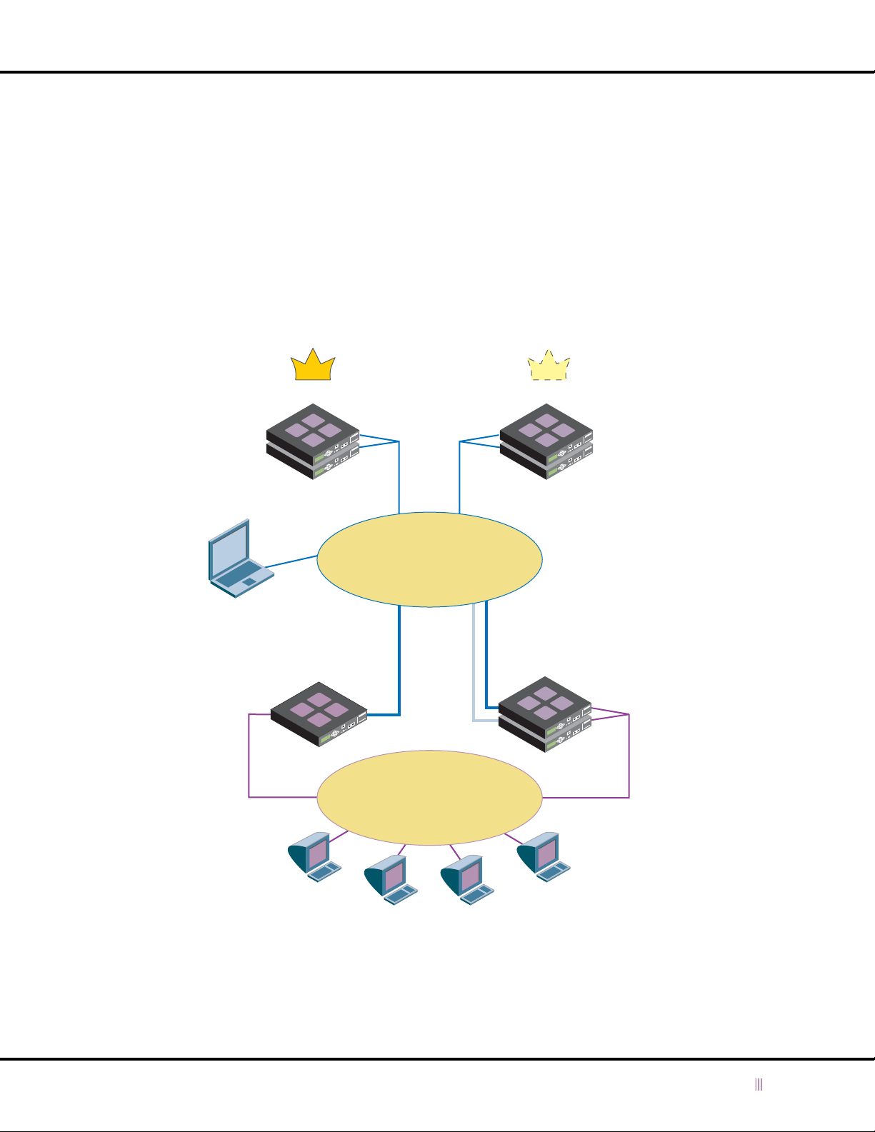
Using the MGMT Port
ID Grid Communications
You can isolate all ID grid communications to a dedicated subnet as follows:
• For grid communications from the grid master, which can be an HA pair or a single device, the master uses either
the VIP interface on the HA port of its active node (HA master) or its LAN port (single master). Neither a single
nor HA grid master can use its MGMT port for grid communications. (This restriction applies equally to master
candidates.)
• Common ID grid members connect to the grid master through their MGMT port.
This ensures that all database synchronization and grid maintenance operations are inaccessible from other network
elements while the common grid members provide network protocol services on their LAN ports.
Figure 4.6
Figure 4.6 ID Grid Communications
shows how grid members communicate to the master over a dedicated subnet.
The private network
(10.1.1.0/24) is reserved for
ID grid communications
between the grid master and
all grid members, and for
device management
between the management
system and the grid master.
Management
System
10.1.1.30
The common grid
members use the public
network (1.1.1.0/24) for
DNS and DHCP services.
HA Grid Master Master Candidate
MGMT
Node
HA
HA
VIP
10.1.1.10
MGMT
10.1.1.21
Active Node
HA Member
Single Member
LAN
1.1.1.6
HA
HA
VIP
10.1.1.5
Private Network
10.1.1.0/24
for ID Grid Communications
and Device Management
MGMT
10.1.1.15
DNS and DHCP Services
10.1.1.20
Passive
Public Network
1.1.1.0/24
HA
HA
VIP
1.1.1.7
The grid master and
master candidate
connect to the private
network using a VIP
on their HA ports.
The common grid
members connect to the
private network through
their MGMT ports*.
They connect to the
public network through
their LAN and HA ports
(using a VIP).
DNS and DHCP Clients
* Only the active node of an HA member connects to the grid master. The
passive node communicates just with the active node. If there is an HA failover,
the newly promoted active node must first join the grid before continuing grid
communications with the grid master on behalf of the HA member.
NIOS 4.0 Infoblox Administrator Guide (Rev. E) 81
Page 82

Chapter 4: Managing Device Operations
Enabling Grid Communications over the MGMT Port for Existing Grid Members
To enable the MGMT port for grid communications on an existing single or HA grid member:
1. Log in to the ID grid master with a superuser account.
2. From the ID Grid perspective, click + (for
3. In the
4. In the
5. Click the Save icon to save your settings.
6. To confirm that the member still has grid connectivity, check that the status icons for that member are green on
ID Grid Member
the IP address, subnet mask, and gateway address for both Node 1 and Node 2.
— Enable management (MGMT) Port: Select the check box.
— Enable VPN services on the MGMT Port: Select the check box.
— Restrict Support and remote console access to MGMT port: Select the check box to restrict SSH (Secure
Shell) v2 access to the MGMT port only. This restricts Infoblox Technical Support and remote console
connections—both of which use SSH v2—to just the MGMT port. For an HA pair, you can make an SSH v2
connection to the MGMT port on both the active and passive nodes.
Clear the check box to allow SSH v2 access to both the MGMT and LAN ports. For an HA pair, you can make
an SSH v2 connection to the MGMT and LAN ports on both the active and passive nodes.
— IP Address: Type the IP address of the MGMT port on the grid member, which must be in a different subnet
from that of the LAN and HA ports.
— Subnet Mask: Choose the subnet mask for the MGMT port IP address.
— Gateway: Type the default gateway for the MGMT port.
— Use automatic MGMT port settings: Select the check box to instruct the Infoblox device to negotiate the
optimum port connection type (full or half duplex) and speed with the connecting switch automatically. If
you clear the check box, manually configure the same settings on both the Infoblox device and the switch.
By default, the check box is selected.
ID Grid Member
member) and LAN and HA ports (for an HA member) if they are in the same subnet as the IP address of the MGMT
port.
The master communicates the new port settings to the member, which immediately begins using them. The
member stops using its LAN port for grid communications and begins using the MGMT port.
the
Detailed Status
editor, click MGMT Port, and then enter the following for Node 1. For an HA member, enter
editor, click LAN/HA Ports, and then change the IP address of the LAN port (for a single
and
ID Grid
panels.
id_grid
) -> + (for Member ) ->
member
-> Edit -> Member Properties.
Enabling Grid Communications over the MGMT Port for New Grid Members
To enable the MGMT port for grid communications on a single device or HA pair and then join it to a grid:
Member MGMT Port Configuration on the Grid Master
1. Log in to the ID grid master with a superuser account.
2. From the ID Grid perspective, click
3. In the
4. In the
82 Infoblox Administrator Guide (Rev. E) NIOS 4.0
ID Grid Member
network and HA settings for an HA member, and clear the Master Candidate check box. Any member that is
a master candidate cannot use the MGMT port for grid communications.
ID Grid Member
For an HA pair, enter the IP address, subnet mask, gateway address, and port settings for both Node 1 and
Node 2.
— Enable management (MGMT) Port: Select the check box.
— Enable VPN services on the MGMT Port: (You must add the member before you can select this check
box, which you do in step 7.)
editor, click LAN/HA Ports, configure the network settings for a single member or the
editor, click MGMT Port, and then enter the following for Node 1 (for a single device).
id_grid
- > Add Grid Member.
Page 83

Using the MGMT Port
— Restrict Support and remote console access to MGMT port: Select the check box to restrict SSH (Secure
Shell) v2 access to the MGMT port only. This restricts Infoblox Technical Support and remote console
connections—both of which use SSH v2—to just the MGMT port. For an HA member, you can make an
SSH v2 connection to the MGMT port on both the active and passive nodes.
Clear the check box to allow SSH v2 access to both the MGMT and LAN ports. For an HA member, you can
make an SSH v2 connection to the MGMT and LAN ports on both the active and passive nodes.
— IP Address: Type the IP address of the MGMT port on the grid member. This is the address that you
previously set when configuring the device. The MGMT port address cannot be in the same subnet as
the addresses of the LAN and HA ports.
— Subnet Mask: Choose the subnet mask for the MGMT port IP address.
— Gateway: Type the default gateway for the MGMT port.
— Use automatic MGMT port settings: Select the check box to instruct the member to negotiate the
optimum port connection type (full or half duplex) and speed with the connecting switch automatically.
If you clear the check box, manually configure the same settings on both the Infoblox device and the
switch. By default, the check box is selected.
5. Click the Save icon to add the member.
6. In the ID Grid perspective, select the member you just created, click Edit -> Member Properties.
7. In the
ID Grid Member
the Save icon.
editor, click MGMT Port, select Enable VPN services on the MGMT Port, and then click
MGMT Port Configuration on Device or HA Pair
8. Log in as a superuser to the MGMT port of the device or active node of the HA pair that you want to join to
the grid.
9. From the ID Grid perspective, click + (for
10. In the
Note: For the remainder of the MGMT port settings, configure the same settings that you previously set for the
11. If the IP addresses of the LAN and HA ports are in the same subnet as the IP address of the MGMT port, click
12. Click the Save icon to save your settings.
13. From the ID Grid perspective, click + (for
14. Enter the following in the
ID Grid Member
device). For an HA pair, enter the IP address, subnet mask, and gateway address for both Node 1 and Node
2.
— Enable management (MGMT) Port: Select the check box.
— Enable VPN services on the MGMT Port: (You cannot select this because the device or HA pair is not yet
a grid member. When the device or HA pair joins the grid, it receives its new configuration from the grid
master, and in that configuration, this option is set.)
single or HA member on the grid master (see step 4 in
Master
LAN/HA Ports in the
member) and LAN and HA ports (for an HA member).
on page 82).
editor, click MGMT Port, and then change the following for Node 1 (for a single
ID Grid Member
Join ID Grid
— Virtual IP of Grid Master: Type the VIP address of the grid master for the ID grid to which you want to add
the single device or HA pair.
— Grid Name: Type the name of the ID grid.
— Grid Shared Secret: Type the shared secret of the ID grid.
— Re-type Grid Shared Secret: To ensure accuracy, retype the shared secret.
— Use MGMT port to join grid: Because you have already enabled the MGMT port, this option is available.
Select it to connect to the ID grid through the MGMT port.
id_grid
) - > + (for Member ) ->
member
-> Edit -> Member Properties.
Member MGMT Port Configuration on the Grid
editor, and then change the IP address of the LAN port (for a single
id_grid
) - > + (for Member ) ->
dialog box:
member
-> Edit -> Join ID Grid.
NIOS 4.0 Infoblox Administrator Guide (Rev. E) 83
Page 84
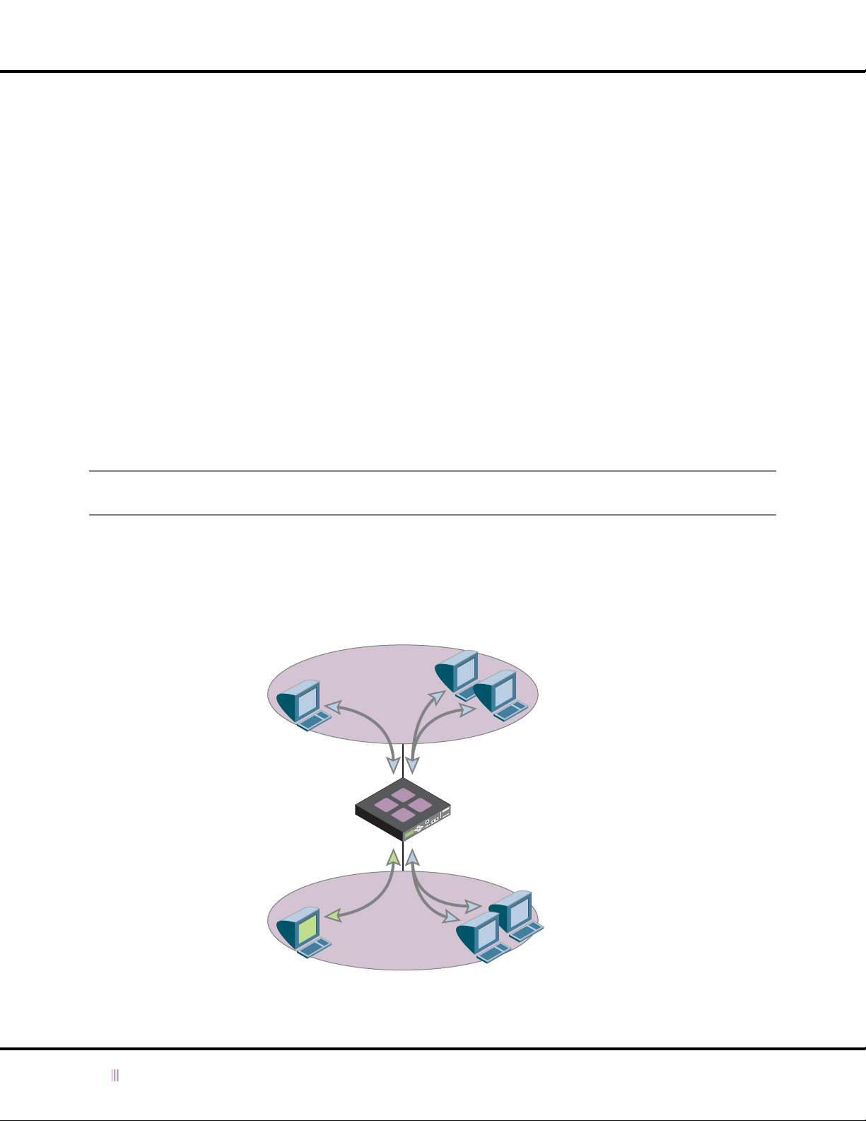
Chapter 4: Managing Device Operations
For a single device, it connects to the grid master from its MGMT port. The grid master allows it to join the grid,
and sends it its configuration and—if the device is running a different software version from the rest of the grid—
the software version for the grid.
When an HA pair joins the grid through their MGMT ports, each node joins separately. The process occurs as
follows:
1. You join the active node to the grid first (step 14) and the grid master sends it the remainder of its
configuration and—if the node is running a different software version from the rest of the grid—the software
version for the grid.
2. The HA pair fails over.
3. You now log in to the other node, which is now active, and join it to the grid (repeat step 14). The master
sends it its configuration and (if necessary) the version of software running on the grid.
4. The HA pair fails over again, so that the node that was active when you started the join operation becomes
the active node again when you finish it.
After a device or HA pair is part of the grid, you continue configuring it through the grid master.
DNS Services
You can configure a single independent device or single grid member to provide DNS services through the MGMT port
in addition to the LAN port. For example, the device can provide DNS services through the MGMT port for internal
clients on a private network, and DNS services through the LAN port for external clients on a public network.
Note: You can use the MGMT port for DNS services only on single independent devices and single grid members.
Infoblox devices in HA pairs do not support DNS services on the MGMT port.
While providing DNS services on the MGMT port, you can still use that port simultaneously for device management.
Figure 4.7
shows a management system communicating with a single independent device through its MGMT port
while the device also provides DNS services on that port to a private network. Additionally, the device provides DNS
services to an external network through its LAN port.
Figure 4.7 DNS Services on the LAN and MGMT Ports, and Device Management on the MGMT Port
External
External DNS services go
through the LAN port.
Device management and
internal DNS services go
through the MGMT port.
Network
LAN
Port
Single
Independent
Device
MGMT
Port
External DNS ClientsExternal DNS Client
Management System
Network
Internal DNS ClientsInternal
Like a single independent device, a single grid member can also support concurrent DNS traffic on its MGMT and LAN
ports. However, because you manage all grid members through the grid master, a grid member only uses an enabled
MGMT port to send SNMP traps, syslog events, and email notifications, and to receive SSH connections.
84 Infoblox Administrator Guide (Rev. E) NIOS 4.0
Page 85

Using the MGMT Port
To enable DNS services on the MGMT port on a single independent device or single grid member:
1. Log in to the single independent device or ID grid master using a superuser account.
2. For a single grid member: From the ID Grid perspective, click + (for
-> Member Properties.
or
For a single independent device: From the ID Device perspective, click
3. In the
4. Click the Save icon to save your settings for the MGMT port.
5. From the DNS perspective of the
6. In the
7. Click the Save icon to save your settings.
8. Click the Restart Services icon if it flashes.
9. To see that the device now also serves DNS on the MGMT port:
ID Grid Member or ID Device
— Enable management (MGMT) Port: Select the check box.
— IP Address: Enter the IP address of the MGMT port. The MGMT port IP address must be in a different subnet
from that of the LAN and HA ports.
— Subnet mask: Choose an appropriate subnet mask for the MGMT port.
— Gateway: Enter the IP address of the gateway for the MGMT port.
-> DNS -> Modify -> General.
Member DNS Properties
From the DNS perspective, click DNS Members -> + (for
General
or
From the DNS perspective, click DNS Members -> + (for
check that the IP address of the MGMT port appears in the address match list in the listen-on substatement.
section. Check that the value for Enable DNS Services on the MGMT Port is true.
editor, click MGMT Port, and then enter the following:
Member DNS Properties
editor, click General, and then select Enable DNS Services on the MGMT Port.
editor, click DNS Members -> + (for
id_grid
id_grid
) ->
member
) ->
member
id_grid
) -> + (for Members) ->
hostname
-> Edit -> ID Device Properties.
id_grid
-> View -> Properties, and look in the
-> View -> DNS Configuration, and
member
) ->
-> Edit
member
NIOS 4.0 Infoblox Administrator Guide (Rev. E) 85
Page 86
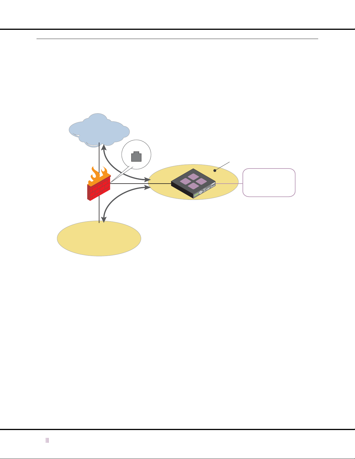
Chapter 4: Managing Device Operations
Setting Static Routes
When you put the Infoblox device on a segment of the network where there is a single path to and from it, a single
default route is sufficient. For example, in
connects to the rest of the network through the DMZ interface on the firewall. For example, when hosts send DNS
queries from the Internet and the internal network to the device and when the device replies to those hosts, the
firewall takes care of all the routing.
Figure 4.8 Single Default Route
Internet
Figure 4.8
1.2.2.1
on page 86, the device is in the DMZ behind a firewall and
The default route points all traffic from the LAN or LAN1
port on the Infoblox device to the DMZ interface (1.2.2.1)
on the firewall.
DMZ
Default route:
LAN
Port
Network: 0.0.0.0
Netmask: 0.0.0.0
Gateway: 1.2.2.1
Firewall
Internal Network
The device responds to all queries from the
Internet and internal network by sending its
responses to the DMZ interface (1.2.2.1) on
the firewall.
The device only needs a single default route
to the firewall. The firewall then routes the
traffic where it needs to go.
Infoblox Device
When the Infoblox device is on a segment of the network where there are multiple gateways through which traffic to
and from the device can flow, a single default route is insufficient. For an example, see
Figure 4.9
.
86 Infoblox Administrator Guide (Rev. E) NIOS 4.0
Page 87
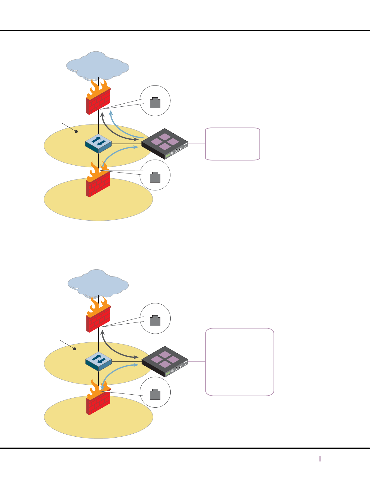
Figure 4.9 Erroneously Routed DNS Replies
Internet
Setting Static Routes
Firewall-1
DMZ
Switch
Firewall-2
Internal Network
10.1.1.0/24
To resolve the problem illustrated in
1.2.2.1
Infoblox Device
1.2.2.2
Figure 4.9
The default route points all traffic from the
Infoblox device to the DMZ interface (1.2.2.1) on
firewall-1.
Default route:
Network: 0.0.0.0
Netmask: 0.0.0.0
Gateway: 1.2.2.1
DNS queries from the Internet reach the
device through firewall-1, and the device
sends its replies back through firewall-1.
DNS queries from the internal network reach
the device through firewall-2, but because
there is only one default route, the device
erroneously sends DNS replies to the DMZ
interface (1.2.2.1) on firewall-1.
on page 87, add a second route pointing traffic destined for
10.1.1.0/24 to use the gateway with IP address 1.2.2.2 on firewall-2. This is shown in
Figure 4.10 Properly Routed DNS Replies
Figure 4.10
.
Firewall-1
DMZ
1.2.2.0/24
Switch
Firewall-2
Internet
Internal Network
10.1.1.0/24
1.2.2.1
Infoblox Device
1.2.2.2
The default route on the Infoblox device
points traffic destined for the Internet to the
DMZ interface (1.2.2.1) on firewall-1.
Default route:
Network: 0.0.0.0
Netmask: 0.0.0.0
Gateway: 1.2.2.1
Route to:
Network: 10.1.1.0
Netmask: 255.255.255.0
Gateway: 1.2.2.2
A second route on the device points tra ffic
destined for 10.1.1.0/24 to the DMZ
interface (1.2.2.2) on firewall-2.
NIOS 4.0 Infoblox Administrator Guide (Rev. E) 87
Page 88
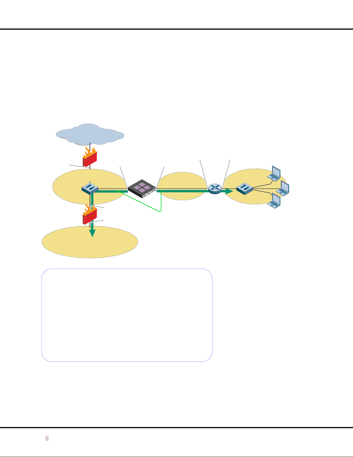
Chapter 4: Managing Device Operations
Whenever you want the Infoblox device to send traffic through a gateway other than the default gateway, you need to
define a separate route. Then, when the device performs a route lookup, it chooses the route that most completely
matches the destination IP address in the packet header.
When you enable the MGMT port, the gateway you reference in a static route determines which port the Infoblox
device uses when directing traffic to a specified destination.
• If a route definition references a gateway that is in the same subnet as the IP and VIP addresses of the LAN (or
LAN1) and HA ports, the Infoblox device uses the LAN (or LAN1) or HA port when directing traffic to that gateway.
• If a route definition references a gateway that is in the same subnet as the MGMT port, the Infoblox device uses
the MGMT port when directing traffic to that gateway.
Figure 4.11 Static Routes for the LAN and MGMT Ports
Internet
LAN Gateway
(Firewall-1)
1.2.2.1
DMZ
1.2.2.0/24
LAN Port
1.2.2.5
Infoblox
Device
10.1.2.5
Subnet
10.1.2.0/24
Switch
LAN Gateway
(Firewall-2)
1.2.2.2
10.1.1.1
Two static routes direct traffic from the Infoblox device:
• From the LAN port (eth1, 1.2.2.5) through the gateway
at 1.2.2.2 to the 10.1.1.0/24 subnet.
Internal Network
10.1.1.0/24
• From the MGMT port (eth0, 10.1.2.5) through the
gateway at 10.1.2.1 to the 10.1.3.0/24 subnet.
Route Tables on the Infoblox Device
From LAN:
1.2.2.0/24 dev eth1 scope link
10.1.1.0/24 via 1.2.2.2 dev eth1
default via 1.2.2.1 dev eth1
From MGMT:
10.1.2.0/24 dev eth0 scope link
10.1.3.0/24 via 10.1.2.1 dev eth0
default via 10.1.2.1 dev eth0
From all:
10.1.1.0/24 via 1.2.2.2 dev eth1
10.1.3.0/24 via 10.1.2.1 dev eth0
1.2.2.0/24 dev eth1 proto kernel scope link src 1.2.2.5
10.1.2.0/24 dev eth0 proto kernel scope link src 10.1.2.5
default via 1.2.2.1 dev eth1
Administrators10.1.2.1 10.1.3.1MGMT Port
MGMT
Gateway
Subnet
10.1.3.0/24
Switch
Note: There is a route table for each port
as well as a comprehensive route table.
For an HA pair, the LAN port route table
is duplicated for the HA port.
In this illustration, the static routes are
shown in green.
The need for routes can apply to any type of traffic that originates from the device, such as DNS replies, DHCP
messages, SNMP traps, ICMP echo replies, Infoblox GUI management, and ID grid communications.
88 Infoblox Administrator Guide (Rev. E) NIOS 4.0
Page 89

Enabling DNS Resolution
To set a static route, do the following:
1. For an ID grid member: From the ID Grid perspective, click + (for
Member Properties.
or
For an independent device or HA pair: From the ID Device perspective, click
Properties.
2. In the
3. Click the Save icon to save your settings.
ID Grid Member
Route
dialog box:
— Network Address: Type the address of the remote network to which you want to route traffic from the
Infoblox device.
— Netmask: Choose the netmask that defines the remote network.
— Gateway Address: Type the IP address of the gateway on the local subnet through which you want the
Infoblox device to direct traffic to reach the remote network.
or
ID Device
editor, click Static Routes, click Add, and then enter the following in the
id_grid
) - > + (for Member s) ->
hostname
member
-> Edit -> ID Device
-> Edit ->
Static
Enabling DNS Resolution
You can specify a network server to perform domain name queries and specify up to two name servers for resolving
a DNS name, plus use a search list to perform partial name resolution.
If an Infoblox device provides DHCP services only, you need to specify a DNS name server or servers that the device
can use for DNS lookups. You specify the IP address of a preferred name server and that of an alternate name server,
plus use a search list for performing partial name resolution.
To enable DNS resolution for an ID grid or for an independent device or HA pair:
1. From the ID Grid perspective, click
or
From the ID Device perspective, click
2. In the
3. Click the Save icon.
ID Grid
— Use DNS name resolver: Select the check box to enable the Infoblox device to send DNS queries to the
preferred or alternate name servers whose IP addresses you specify in the following fields.
— Preferred Name Server: Type the IP address of the name server to which you want the Infoblox device to
send queries first.
— Alternate Name Server: Type the IP address of the name server to which you want the Infoblox device to
send queries if it does not receive a response from the preferred name server.
— Search Domain Group: Define a group of domain names that the Infoblox device can add to partial queries
that do not specify a domain name. For example, if you define a RADIUS authentication home server as
“as1”, and you list "corp100.com" and "hq.corp100.com" in the domain group list, then the Infoblox device
sends a query for "as1.corp100.com" and another query for "as1.hq.corp100.com" to the preferred or
alternate name server.
To add a domain name to the group, type a domain name in the Domain field, and then click Add.
To remove a domain name from the group, select it, and then click Delete.
editor, click DNS Resolver, and then enter the following:
id_grid
hostname
-> Edit -> Grid Properties.
-> Edit -> ID Device Properties.
Note: You can override the ID grid-level settings at the member level.
NIOS 4.0 Infoblox Administrator Guide (Rev. E) 89
Page 90

Chapter 4: Managing Device Operations
Managing Licenses
Licenses come pre-installed on an Infoblox device according to the software packages you ordered at the time of
purchase. If you wish to upgrade an existing device with the Keystone license, you must contact Infoblox Technical
Support and follow the procedures in
Viewing the Installed Licenses on an Infoblox Device
If the device you are identifying is part of an ID grid, you must log in to the master GUI for the grid to view the licenses
installed. If the device is deployed as a single independent device, log in to the GUI for that device.
To view the licenses installed on an Infoblox device, follow these steps:
1. Log in to the Infoblox ID Manager GUI using a superuser account.
2. From the ID Grid or ID Device perspective, click
3. Click the + icon beside the
Obtaining a 60-Day Temporary License
You can use the CLI command set temp_license to generate and install a temporary 60-day license. This can
provide licensed features and functionality for the interim, while you wait for your permanent license to arrive.
To generate a temporary license:
1. Log in to the Infoblox device through a remote console window. For more information on how to open a remote
console window, see the User Guide for your device.
2. After the Infoblox command prompt, enter the following command:
set temp_license
The following options appear:
1.
IDeal IP (DNS, DHCP, IPAM) on Infoblox-500/550 only
2. VitalQIP & Keystone (VIM, Keystone)
3. DNSone (DNS, DHCP)
4. DNSone & Keystone (DNS, DHCP, IPAM, Keystone)
Select license (1-4):
3. Enter the number for the license you want to install.
4. Confirm the selection when prompted, and the following message appears:
Temporary license is installed.
Obtaining and Adding a License
hostname
License
section to expand it and view the licenses installed on the device.
.
-> View -> Properties.
Obtaining and Adding a License
A valid Keystone license is required for ID grid Infoblox device deployments. You can upgrade existing independent
devices to use a Keystone license and then add them to a grid. Contact Infoblox Support at
upgrade your license.
To obtain and add a license:
1. Log in to the Infoblox ID Manager GUI using a superuser account.
2. From the ID Grid or ID Device perspective, click
3. In the
4. When you receive the license key, use the shortcut keys Ctrl-C (for copy) and Ctrl-V (for paste) to copy the license
5. Click OK to close the
6. Close the browser window and log in to the Infoblox ID Manager GUI.
7. If you are activating licenses for an HA pair, you must repeat this procedure for the second node.
90 Infoblox Administrator Guide (Rev. E) NIOS 4.0
Add License
into an e-mail to Infoblox Support.
key from the response e-mail, and then paste it in the Enter license string field.
dialog box, copy the hardware ID and serial number of your device and paste this information
Add License
dialog box.
hostname
-> Edit -> Add License.
Page 91

Managing Licenses
Removing Licenses
You can remove licenses and reset an Infoblox device to its factory default settings. For example, if you have an
Infoblox device running the DNSone package with the Keystone upgrade, but you want to use it as an independent
device and manage it through the ID Device Manager GUI, you can do the following:
1. Log in to the Infoblox device CLI—locally through the Console port or remotely through an SSHv2 connection—
and use the
The output of the the
Infoblox > show license
Version: 4.0r1
Hardware ID: ecafc0c469e8c75eb59cb7e4b5912a6
License Type: Keystone DVS
Expiration Date: 11/04/2006
License String: GQAAAAOS5WYrGV/JEzH6wrHYQ8L1b25y3Y+VPPY=
License Type: DNS
Expiration Date: Permanent
License String: EQAAAAKS4n90WFGNUSirwvyUT9/z
License Type: DHCP
Expiration Date: Permanent
License String: EgAAAAKU8nMlRBzcTWX63rHYFoymOQ==
show license command to view all the licenses installed on the device.
show license command looks similar to the following:
License Type: Keystone Maintenance
Expiration Date: 11/04/2006
License String: GwAAAA2Z6HAtBkPFPyfzg/yVRsLzI2x0kYyKaPb22g==
License Type: NIOS Maintenance
Expiration Date: 11/04/2006
License String: GwAAAAiV/nAGGljQEDv0h/yVRsLzI2x0kYyKb/P20Q==
2. Copy the output of the show license command, and save it to a text file on your management system.
3. Reset the Infoblox device and remove all the licenses by entering the
reset all licenses command.
4. This command returns all settings to their default values and removes all licenses.
Infoblox > reset all licenses
The entire system will be erased to default settings and all licenses will be removed.
WARNING: THIS WILL ERASE ALL DATA AND LOG FILES THAT HAVE BEEN CREATED ON THIS SYSTEM.
ARE YOU SURE YOU WANT TO PROCEED? (y or n): y
The application restarts with the default settings and no licenses.
5. Log in to the CLI through the Console port, and check that all the licenses are gone by entering the
show license
Infoblox > show license
Version: 4.0r1
Hardware ID: ecafc0c469e8c75eb59cb7e4b5912a6
Infoblox >
command.
NIOS 4.0 Infoblox Administrator Guide (Rev. E) 91
Page 92

Chapter 4: Managing Device Operations
6. Add back only the DNS, DHCP, and NIOS Maintenance licenses by entering the set license command and
then copying and pasting the text string for each license:
Infoblox > set license
Enter license string: EQAAAAKS4n90WFGNUSirwvyUT9/z
Install license? (y or n): y
License is installed.
Infoblox > set license
Enter license string: EgAAAAKU8nMlRBzcTWX63rHYFoymOQ= =
Install license? (y or n): y
License is installed.
Infoblox > set license
Enter license string: GwAAAAiV/nAGGljQEDv0h/yVRsLzI2x0kYyKb/P20Q==
Install license? (y or n): y
License is installed.
7. To check that the licenses are now installed, enter the show license command.
When you next log in to the GUI, the Infoblox ID Device Manager appears instead of the Infoblox ID Grid
Manager.
92 Infoblox Administrator Guide (Rev. E) NIOS 4.0
Page 93

Shutting Down, Rebooting, and Resetting an Infoblox Device
Shutting Down, Rebooting, and Resetting an Infoblox Device
To reboot and shut down an Infoblox device, you can use the Infoblox ID Manager GUI or the Infoblox CLI. To reset a
device, you must use the Infoblox CLI.
Rebooting a Device
You can reboot a single device, a single no de in an HA pair, or both nodes in an HA pair. When yo u reboot both nodes,
the active node reboots first, and then the passive node reboots.
To reboot a single device or one or both nodes in an HA pair using the GUI:
1. From the ID Grid or ID Device perspective, click
2. For an HA pair, choose whether to boot one node (and which one) or both nodes, and then click OK.
To reboot a single device using the CLI:
1. Log in to the Infoblox CLI using a superuser account for the device that you intend to reboot.
2. Enter the following CLI command:
reboot
Shutting Down a Device
hostname
-> Edit -> Reboot.
Under normal circumstances, you do not need to turn off or shut down an Infoblox device. It is designed to operate
continuously. However, if you want to turn off an Infoblox device and it is inconvenient to turn off the power switch,
you can shut down the Infoblox device using the GUI. Before shutting down a remote device, make sure you can
restart it. You cannot restart the system using the GUI.
Note: If there is a disruption in power when the Infoblox device is operating, the Infoblox device automatically
reboots itself when power is restored.
To shutdown an Infoblox device using the GUI:
1. Log in to the Infoblox ID Manager GUI using a superuser account.
2. From the ID Grid or ID Device perspective, click
3. For an HA pair, choose whether to shut down one node (and which one) or both nodes, and then click OK.
The Infoblox device shuts down. The fans might continue to operate until the device cools down.
To shutdown an Infoblox device using the CLI:
1. Log in to the Infoblox CLI using a superuser account.
2. Enter the following CLI command:
shutdown
hostname
-> Edit -> Shutdown.
Resetting a Device
There are three ways to reset an Infoblox device:
•
Resetting the Database
•
Resetting a Device to Factory Settings
•
Resetting the Device to Factory Settings and Removing Licenses
You can perform these functions only through the CLI.
on page 94
on page 94
on page 94
NIOS 4.0 Infoblox Administrator Guide (Rev. E) 93
Page 94

Chapter 4: Managing Device Operations
Resetting the Database
You can reset the database if you lose the administrator account and password or if you want to clear the database
but preserve the log files to diagnose a problem. This function removes the configuration files, and the DNS and DHCP
data from the device database. During this procedure, you are given the option to preserve the network settings of
the device, which are the IP address and subnet mask, the IP address of the gateway, the host name, and the remote
access setting.
To reset the database:
1. Log in to the Infoblox CLI using a superuser account.
2. Enter the following CLI command:
The device then displays a message similar to the following:
The following network settings can be restored after reset:
IP Address: 10.1.1.10
Subnet Mask: 255.255.255.0
Gateway: 10.1.1.1
Host Name: ns1.corp100.com
Remote Console Access: true
The entire database will be erased.
Do you wish to preserve basic network settings? (y or n)
3. Press the Y key to preserve the network settings or the N key to return the network settings to their default values
(192.168.1.2, 255.255.255.0, 192.168.1.1).
reset database
Resetting a Device to Factory Settings
You can reset an Infoblox device to its original factory settings. This removes the database, network settings, logs,
and configuration files. Then, it reboots with its factory settings, which are the default user name and password, and
default network settings. When you perform this procedure, the device does not give you the option to preserve your
network settings.
Note: If you have previously imported HTTPS certificates, the device regenerates the certificates and replaces them.
To reset the device to its factory settings:
1. Log in to the Infoblox CLI using a superuser account.
2. Enter the following CLI command:
reset all
Resetting the Device to Factory Settings and Removing Licenses
You can also reset an Infoblox device to its original factory settings and remove all the licenses installed on the
device. This removes the database, network settings, logs, configuration files, and licenses. The device then reboots
with its factory settings, which are the default user name and password, and default network settings.
Note: If you have previously imported HTTPS certificates, the device regenerates the certificates and replaces them.
To reset the device to its factory settings and remove all its licenses:
1. Log in to the Infoblox CLI using a superuser account.
2. Enter the following CLI command:
reset all licenses
94 Infoblox Administrator Guide (Rev. E) NIOS 4.0
Page 95

Chapter 5 Monitoring the Device
Managing the operations of an Infoblox device involves controlling administrator accounts, defining primary
configuration settings and security, and monitoring system functions. The operations covered in this chapter include:
•
Managing Device Monitoring Operations
—
Using a Syslog Server
—
Viewing the System Log
—
Setting DNS Logging Categories
—
Viewing the Audit Log
—
Viewing a Replication Log
—
Using the Traffic Capture Tool
•
Monitoring with SNMP
—
MIBs (Management Information Bases)
—
SNMP Traps
—
Configuring SNMP
•
Modifying Monitoring for a Grid Member
on page 105
on page 96
on page 97
on page 98
on page 99
on page 100
on page 106
on page 96
on page 98
on page 99
on page 101
on page 107
NIOS 4.0 Infoblox Administrator Guide (Rev. E) 95
Page 96

Chapter 5: Monitoring the Device
Managing Device Monitoring Operations
The procedures in this section apply to both independent and ID grid deployments.
You can enable syslog servers and SNMP trap receivers to receive messages, plus notify an administrator if a problem
occurs. (You can supply notification information for an administrator even if you do not enable a syslog server or trap
receiver.) The topics in this section include:
•
Using a Syslog Server
•
Viewing the System Log
•
Setting DNS Logging Categories
•
Viewing the Audit Log
•
Viewing a Replication Log
•
Using the Traffic Capture Tool
For information about SNMP, see
Using a Syslog Server
YOu can configure the device to send syslog messages to a syslog server. These messages provide information about
device operations and processes. This function is helpful when performing troubleshooting and diagnostic
procedures.
To enable a syslog server:
1. From the ID Grid perspective, click
or
From the ID Device perspective, click
2. In the
3. Click the Save icon to save your settings.
ID Grid
— Enable external syslog server: Select this check box to enable the Infoblox device to send messages to a
specified syslog server.
— Syslog Server Group: To define one or more syslog servers, click Add, enter the following, and then click OK:
— Server Address: Type the IP address of a syslog server.
— Connection Type: Specify whether the device uses TCP or UDP to connect to the external syslog server.
— Port: Specify the destination port number.
— Out Interface: Specify the interface through which the device sends syslog messages to the syslog
— Severity Filter: Choose a filter from the drop-down list. When you choose a severity level, grid members
— Message Source: Specify which syslog messages the device sends to the external syslog server:
— Copy audit log messages to syslog: Select the check box for the Infoblox device to include audit log
messages among the messages it sends to the syslog server. This function can be helpful for monitoring
administrative activity on multiple devices from a central location.
— Audit Log Facility: Choose the facility where you want the syslog server to sort the audit log messages.
or
ID Device
server.
send messages for that severity level plus all messages for all severity levels above it. The lowest
severity level is debug (at the top of the drop-down list), and the highest severity level is emerg (at the
bottom of the list). Accordingly, if you choose “debug”, grid members send all syslog messages to the
server. If you choose “err”, grid members send messages with the severity levels err, crit, alert, and
emerg. If you choose “emerg”, they send only “emerg” messages.
• Internal: The device sends syslog messages that it generates.
• External: The device sends syslog messages that it receives from other devices, such as syslog
servers and routers.
• Any: The device sends both internal and external syslog messages.
on page 97
on page 98
on page 98
on page 99
on page 99
Monitoring with SNMP
id_grid
-> Edit -> Grid Properties.
hostname
editor, click Monitoring, and then enter the following:
on page 100.
-> Edit -> ID Device Properties.
96 Infoblox Administrator Guide (Rev. E) NIOS 4.0
Page 97

Managing Device Monitoring Operations
Viewing the System Log
In addition to saving syslog messages to a remote syslog server, an Infoblox device also stores the system messages
locally. To view syslog messages on an Infoblox device:
1. From the ID Grid perspective, click + (for
or
From the ID Device perspective, click
Note: You can also right-click a grid member or independent device or HA pair, and then select System Log ->
ip_addr
The device displays the syslog messages for the specified member.
2. To refresh the contents in the
3. To delete the contents in the
syslog file.
in the short-cut menu.
System Log File
System Log File
Searching for Text
Instead of paging through the syslog messages to locate messages, you can limit the display to syslog messages with
certain text strings. To search for specified text strings:
1. From the ID Grid perspective, click + (for
or
From the ID Device perspective, click
id_grid
hostname
viewer, click View -> Clear. Note that only a superuser can clear the
id_grid
hostname
) -> + (for Members) ->
-> File -> System Log ->
viewer, click View -> Refresh (or press the F5 key).
) -> + (for Members) ->
-> File -> System Log ->
member
ip_addr
member
ip_addr
-> File -> System Log ->
.
-> File -> System Log ->
.
ip_addr
ip_addr
.
.
Note: You can also right-click a grid member or independent device or HA pair, and then select System Log ->
ip_addr
The device displays the syslog messages for the specified member.
2. Click the Search icon in the upper right corner of the
3. Enter the text string and then click Search.
The device displays the results of your search in a
in the short-cut menu.
System Log File
Search Results
viewer.
panel.
Downloading the Syslog File
You can download the syslog file to a specified directory, if you want to print and analyze it.
To download a syslog file:
1. From the ID Grid perspective, click + (for
or
From the ID Device perspective, click
Note: You can also right-click a grid member or independent device or HA pair, and then select System Log ->
ip_addr
The device displays the syslog messages for the specified member.
2. Click the Download File icon in the upper right corner of the
you want to save it, optionally change the file name (the default names are
node_2_sysLog.tar.gz
in the short-cut menu.
), and then click OK.
id_grid
hostname
) -> + (for Members) ->
-> File -> System Log ->
System Log File
member
ip_addr
-> File -> System Log ->
.
viewer, navigate to a directory where
node_1_sysLog.tar.gz
and
ip_addr
.
NIOS 4.0 Infoblox Administrator Guide (Rev. E) 97
Page 98

Chapter 5: Monitoring the Device
Setting DNS Logging Categories
You can specify which of 14 BIND logging message categories you want syslog to capture, and furthermore, you can
filter these messages by severity. For information about severity types, refer to
To specify logging categories:
1. From the ID Grid perspective, click + (for
or
From the ID Device perspective, click + (for
2. In the
3. Click the Save icon to save your settings.
4. Click the Restart Services icon if it flashes.
ID Grid DNS Properties
— Logging Facility: Select a facility from the drop-down list. This is the location on the syslog server to which
you want to sort the DNS logging messages.
— Select one of more of these log categories:
— Enable General: Records the BIND messages that are not specifically classified.
— Enable Config: Records the configuration file parsing messages.
— Enable DNSSEC: Records the DNSSEC-signed responses.
— Enable Network: Records the network operation messages.
— Enable Queries: Records the query response messages.
— Enable Security: Records the approved and denied requests.
— Enable Transfer-in: Records zone transfer messages from the remote name servers to the device.
— Enable Transfer-out: Records zone transfer messages from the Infoblox device to remote name servers.
— Enable Update: Records the dynamic update instances.
— Enable Resolver: Records the DNS resolution instances, including recursive queries from resolvers.
— Enable Notify: Records the asynchronous zone change notification messages.
— Enable Lame Servers: Records bad delegation instances.
— Enable Database: Records BIND’s internal database processes.
— Enable Client: Records client requests.
editor, click Logging, and then enter the following:
id_grid
) -> + (for Services) -> DNS -> Service Properties.
hostname
) -> DNS -> Service Properties.
Using a Syslog Server
on page 96.
Viewing the Audit Log
The audit log contains a record of all Infoblox administrative activity.
To view an audit log:
1. From the ID Grid perspective, click
or
From the ID Device perspective, click
2. To refresh the contents in the
3. To delete the contents in the
syslog file.
Note: You can search and download the audit log as you can the system log. For information, see
on page 97 and
98 Infoblox Administrator Guide (Rev. E) NIOS 4.0
Downloading the Syslog File
id_grid
hostname
Audit Log File
Audit Log File
-> File -> Audit Log.
-> File -> Audit Log .
viewer, click View -> Refresh (or press the F5 key).
viewer, click View -> Clear. Note that only a superuser can clear the
Searching for Text
on page 97.
Page 99

Managing Device Monitoring Operations
Viewing a Replication Log
The
Replication Status
Replication Status
between the two nodes in an independent HA pair. You can use this information to check the health of grid and HA
pair activity.
To view the replication log:
1. From the ID Grid perspective, click
or
From the ID Device perspective, click
2. To refresh the contents in the
panel reports the status of the database replication between ID grid members and master. The
panel reports the status of the database replication between ID grid members and master, and
id_grid
-> View -> Replication Status.
hostname
Replication Log
-> View -> Replication Status .
viewer, click View -> Refresh (or press the F5 key).
Using the Traffic Capture Tool
You can capture the traffic on one or all of the ports on an Infoblox device, and then view it using a third-party network
protocol analyzer application, such as the Ethereal – Network Protocol Analyzer™.
The Infoblox device saves all the traffic it captures into a .cap file and compresses it into a .tar.gz file. Your
management system must have a utility that can extract the .tar file from the .gzip file, and an application that can
read the .cap (capture) file format. This section explains the process of first capturing traffic, and then downloading
it to your management system. After that, you can extract the traffic capture file and view it with a third-party traffic
analyzer application.
Note: The Infoblox device always saves a traffic capture file as
traffic capture files to the same location, rename each downloaded file before downloading the next.
1. From the ID Grid perspective, click -> + (for
or
From the ID Device perspective, click
2. In the
3. Click Start.
4. Click Yes.
5. When you want to view the captured traffic, click Download.
6. Another message appears stating that clicking Download causes the traffic capture operation (if it is still ongoing)
7. Click OK.
8. Navigate to where you want to save the file, rename it if you want, and then click OK or Save.
9. Use terminal window commands (Linux) or a software application (such as StuffIt™ or WinZip™) to extract the
10. When you see the traffic.cap file in the directory where you extracted the .tar.gz file, open it with the third-party
Traffic Capture
— HA port: Select to capture all traffic that the HA port receives and transmits.
— LAN port: Select to capture all traffic that the LAN port receives and transmits.
— MGMT port: Select to capture all traffic that the MGMT port receives and transmits.
— All ports (promiscuous mode not supported): Select to capture traffic addressed to all ports. Note that the
Infoblox device only captures traffic that is addressed to it.
— Seconds to run: Specify the number of seconds that you want the traffic capture tool to run.
A message appears warning that the use of the traffic capture tool causes a decrease in network service
processing and prompts you to confirm your use of the tool.
to stop and asks if you want to proceed.
contents of the .tar.gz file.
network protocol analyzer application.
dialog box, enter the following:
id_grid
hostname
) -> + (for Members) ->
-> Tools -> Capture Traffic.
tcpdumpLog.tar.gz
member
. If you want to download multiple
-> Tools -> Capture Traffic.
NIOS 4.0 Infoblox Administrator Guide (Rev. E) 99
Page 100
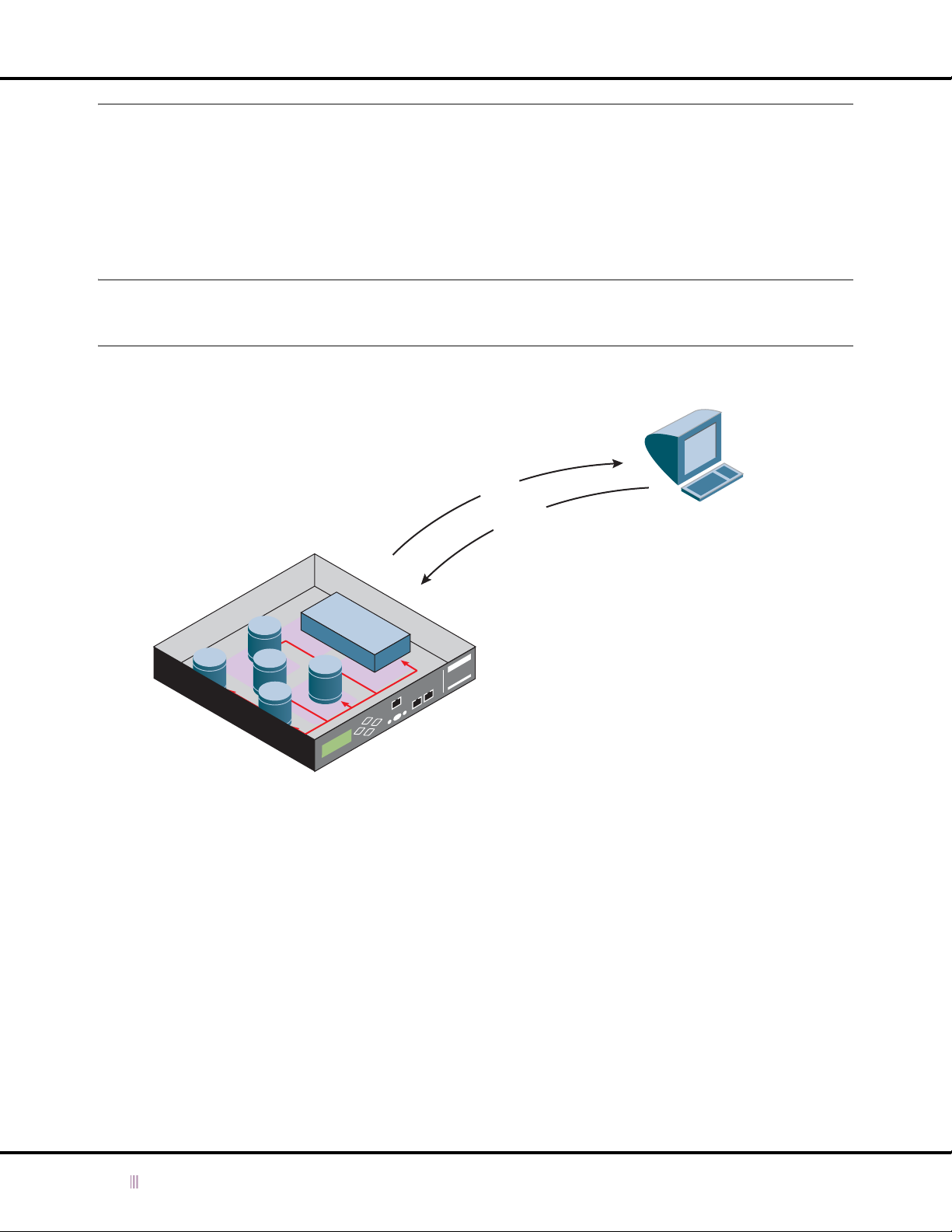
Chapter 5: Monitoring the Device
Monitoring with SNMP
You can use SNMP (Simple Network Management Protocol) to monitor SNMP-enabled devices in your network. The
SNMP agent on an Infoblox device collects data and stores them as objects in MIBs (Management Information Bases).
Each object represents specific information, such as the location of the device or how long it has been up. Similar
objects are grouped together into MIBs. You can send queries to obtain the data stored in the MIBs. In addition, the
SNMP agent can also send traps (or notifications) to alert you when certain events occur within the device or on the
network.
Note: You can view data in the SNMP MIBs and receive SNMP traps only on a management system running an SNMP
management application, such as HP OpenView, IBM Tivoli NetView, or any of the freely available or
commercial SNMP management applications on the Internet.
Figure 5.1 SNMP Overview
Traps
Infoblox Device
MIB
MIB
MIB
MIB
Queries
Agent
MIB
SNMP Management System
Infoblox devices support SNMP versions 1 and 2 and adhere to the following RFCs:
• RFC 3411, An Architecture for Describing Simple Network Management Protocol (SNMP) Management
Frameworks
• RFC 3412, Message Processing and Dispatching for the Simple Network Management Protocol (SNMP)
• RFC 3413, Simple Network Management Protocol (SNMP) Applications
• RFC 3416, Version 2 of the Protocol Operations for the Simple Network Management Protocol (SNMP)
• RFC 3418, Management Information Base (MIB) for the Simple Network Management Protocol (SNMP)
•
RFC 1155, Structure and identification of management information for TCP/IP-based internets
• RFC 1213, Management Information Base for Network Management of TCP/IP-based internets:MIB-II
100 Infoblox Administrator Guide (Rev. E) NIOS 4.0
 Loading...