

Page 1
Models:
SSW-10 subwoofer
Infinitesimal IV subwoofer
Servo Controlled subwoofer
RS Subwoofer
SERVICE MANUAL
Infinity Systems Incorporated
250 Crossways Park Dr.
Woodbury, New York 11797 Rev0 12/2003
Page 2

CONTENTS
1
SPECIFICATIONS/PRODUCT ID……………..…….…….……….……………1
INSTALLATION/CONTROLS…………………..…….……………..……………2
OPERATION………………………………………..………………..…………….4
CIRCUIT DESCRIPTION…………………………..………………..……………5
THEORY OF OPERATION…………………………..…………….……………11
DETAILED TROUBLESHOOTING…………………….………….……………18
EXPLODED VIEW S………………………………………………….…………..24
MECHANICAL/ELECTRICAL PARTS LISTS……………………….…………26
PCB DRAWINGS…………………………………………………………………33
POWER TRANSFORMER………………………………………………………35
SEMICONDUCTOR PINOUTS…………………………………………………36
SCHEMATICS (Infinitesimal IV/SSW-10/Servo Controlled Subwoofer)……37
SCHEMATICS (RS Subwoofer)……………………………………….. ………38
PACKING (Infinitesimal IV/SSW-10/Servo Controlled Subw oofer)……..…… 39
SPECIFICATIONS
Frequency Response 40 - 200 Hz
Crossover Frequency 40 - 200 Hz (Continuously Variable)
Output Power 100 Watts (RMS) into 2 ohms
THD (@ 75 W/100 Hz) < .l %
Signal to noise ratio > 80db
Input Impedance 25K Ω
Driver 10" (254mm) IMG Woofer - (DCR = 1.8 Ω)
Inputs Line Level and Speaker Level
Outputs
Infinitesimal IV/SSW-10/Servo Controlled Subwoofer Full Range Speaker
RS Subwoofer 180 Hz High Pass Filter
Dimensions
Infinitesimal IV/SSW-10/Servo Controlled Subwoofer 13.25" x 13.25" x 13" (337 x 337 x 330mm)
RS Subwoofer 23.25" x 7.25" x 13.25" (59x18.5 x 33.5mm)
Weight (Infinitesimal IV/SSW-10/Servo Controlled Subwoofer) 34 lbs. (15.4kg)
PRODUCT IDENTIFICATION
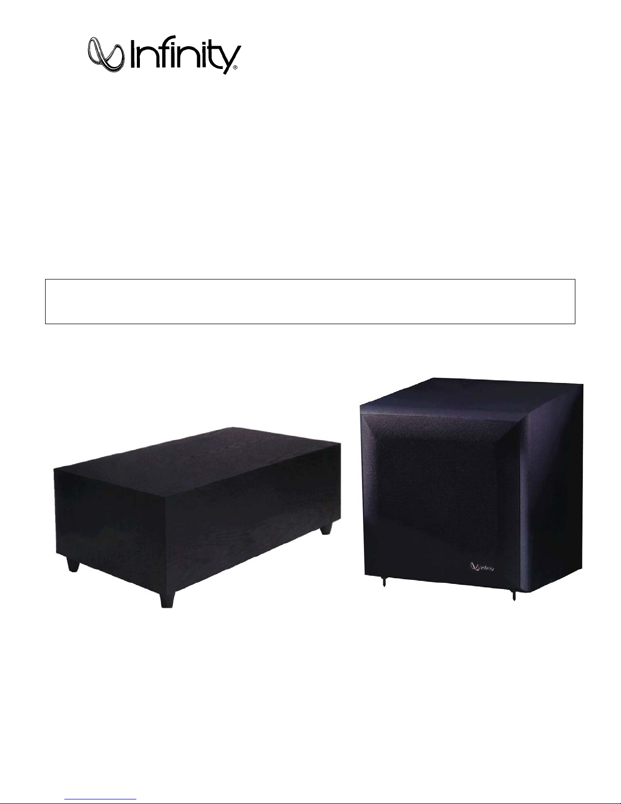
SSW-10 subwoofer
Infinitesimal IV subwoofer
Servo Controlled subwoofer
RS Subwoofer (actually a different product, but the amplifier is nearly identical)
The Infinitesimal subwoofer, Infinitesimal IV Subwoofer, SSW-10, or Servo Controlled Subwoofer may
be identified from the owner's manual, outer carton or amplifier plate. It is a square black cube and is ported.
Alternately, the RS Subwoofer has a distinct rectangular enclosure. The differences in the RS Subwoofer
include a non- r emovable power cor d, two high level input terminals, and a passive high-pass filter for satellite
speakers (activ e when the high level input terminals a re utilized). There is no port .
This service manual covers the following models:
Page 3
2
Page 4
3
Page 5
4
Page 6

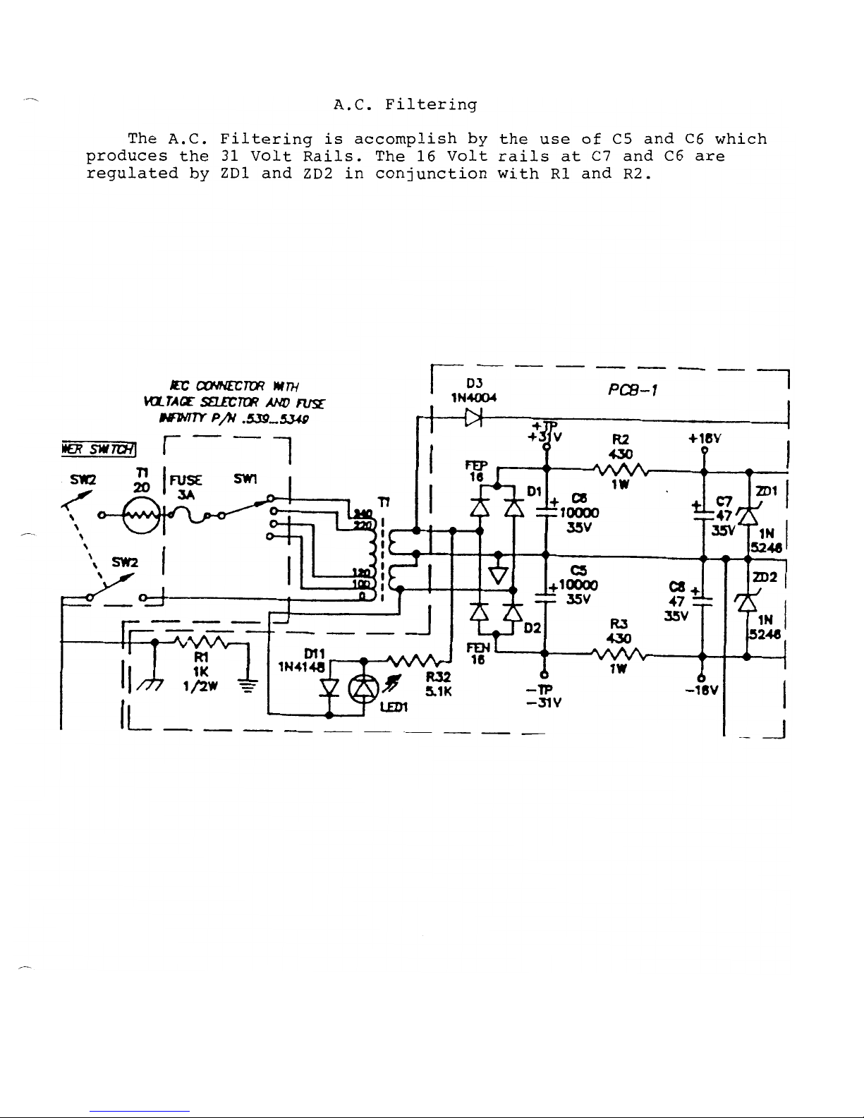
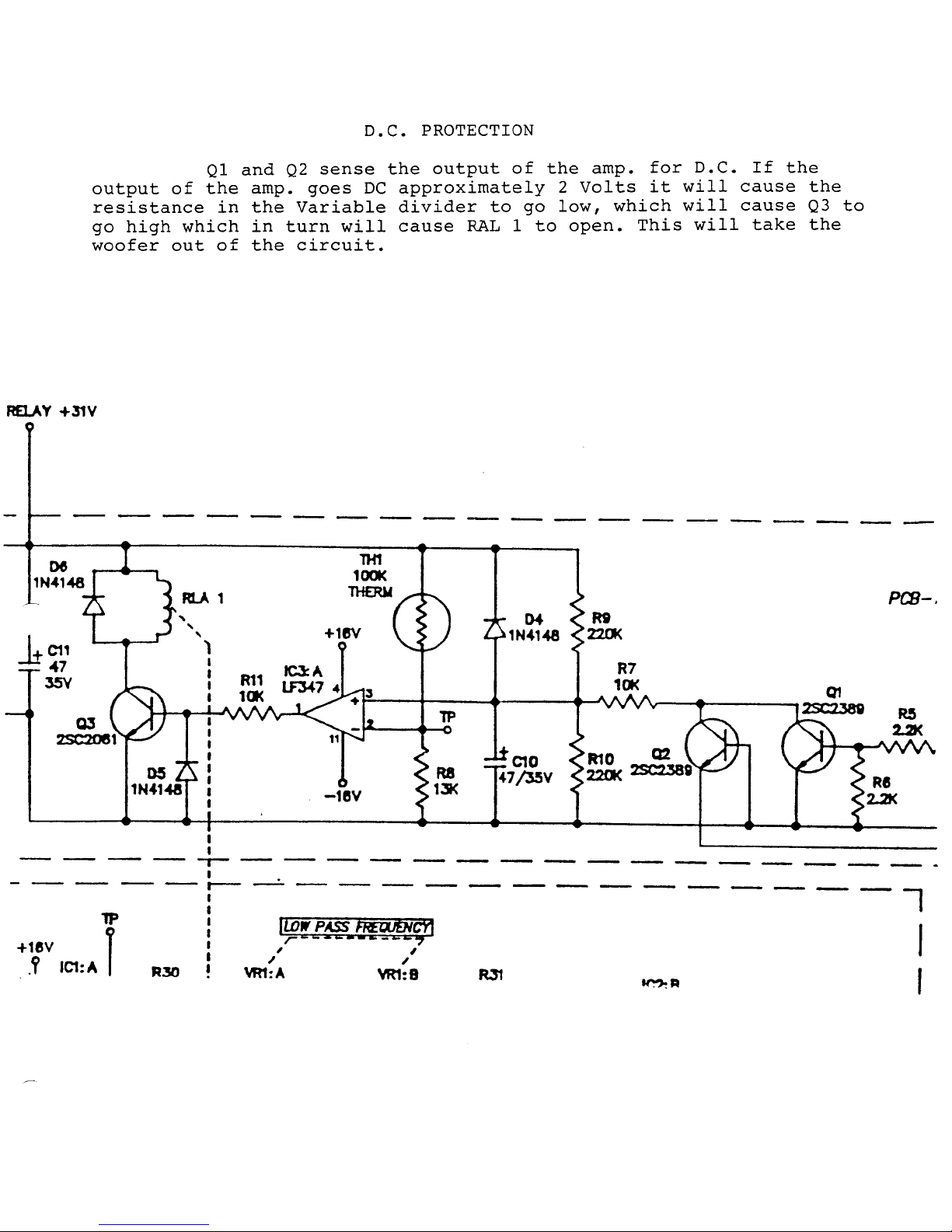
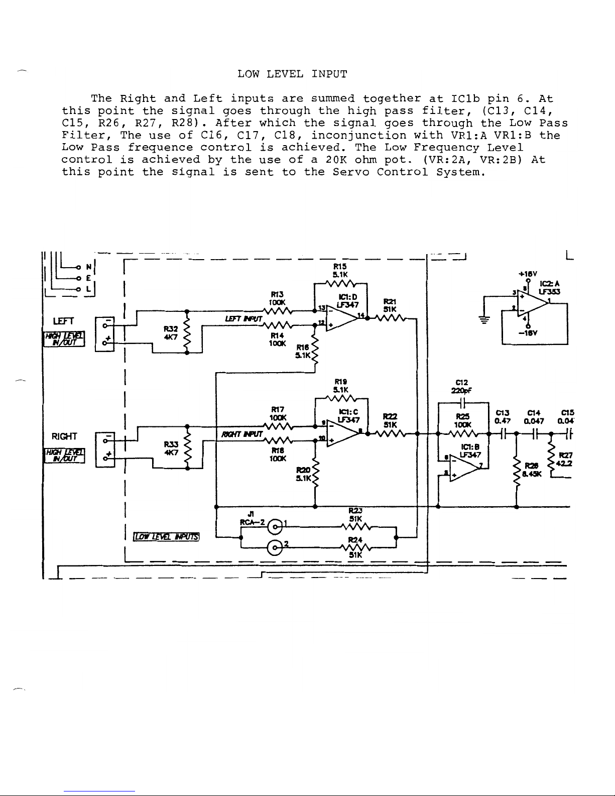
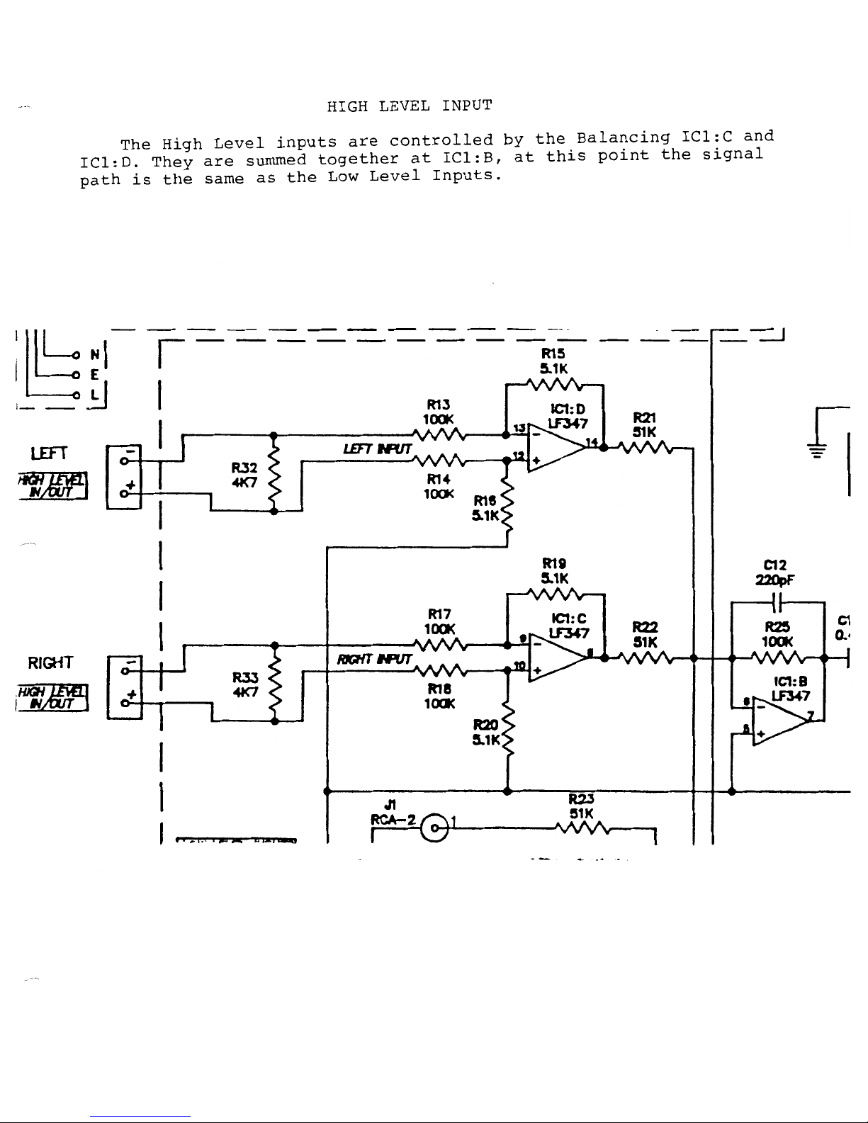
CIRCUIT DESCRIPTION
5
Page 7
CIRCUIT DESCRIPTION (cont'd)
6
Page 8
CIRCUIT DESCRIPTION (cont'd)
7
Page 9
CIRCUIT DESCRIPTION (cont'd)
8
Page 10
CIRCUIT DESCRIPTION (cont'd)
9
Page 11
CIRCUIT DESCRIPTION (cont'd)
10
Page 12
THEORY OF
OPERATION
11
Page 13

THEORY OF
OPERATION
12
Page 14

Page 15

THEORY OF
OPERATION
14
Page 16

THEORY OF
OPERATION
15
Page 17

THEORY OF
OPERATION
16
Page 18

Page 19

18
TROUBLESHOOTING
the RS/SSW-I0/INFINITESIMAL IV SUBWOOFER Amplifer
We are assuming at this point the unit has been tested and there is either distortion, no output,
"breathing" from woofer, it blows fuses instantly, etc. If the problem is no output whatsoever and the
woofer does not react at all upon hearing the relay close, disconnect and check the DCR of the
woofer with a DMM; it should be 1.7 -2.2 Ω (to rule out a defective woofer). Another simple external
problem that can be responsible for little or no output is: using the high level input terminals and
having one polarity reversed on either input cable — (the right and left signal will effectively cancel at
the subwoofer input.) The relay should close (an audible "click") 2 - 5 seconds after turning on the
unit. And obviously if no "click" is heard the relay has not closed and there will be no output.
However whether the relay closes or not is of no consequence in the early stages of
troubleshooting once the unit has been found defective. 99% of the time the relay itself is not
defective.
FOR ALL PROBLEMS (EXCEPT BLOWING FUSES, SEE SECTION IV):
After amplifier removal from cabinet, pull back plastic cover (NOTE: plastic amp cover not present on
early RS Subwoofer models) and examine PC-1 (main circuit board). It is usually not necessary to
completely detach the amp cover from the amp assembly.
I RELAY IS CLOSING NORMALLY (Audible "click" is heard 1 - 5 seconds after power is turned
on):
A. R2 & R3, 430Ω 1watt resistors are burnt up or discolored: problem is most likely
defective ICI and IC2 on PC-2 (the small input board) OR one or both of the zener diodes in
the power supply.
B. To check, replace R2 & R3, power up unit and check DC voltages across R2 & R3; it
should be ± 11-14 VDC. If voltage is higher, remove socketed ICI and IC2 (LF347N &
LF353N) on PC-2 (the small input board) or unsolder 5 - conductor ribbon attaching PC-1 to
PC-2. If no change in voltage, on R2 replace ZDI, on R3 replace ZD2. If voltage is normal
OR drops to normal after IC removal/unsoldering ribbon, replace ICI and IC2 on PC-2
(the small input board). If the IC's are in sockets (the latest model) it will be easy; if not the two
IC's must be desoldered and removed without damaging the rest of the board. IC sockets are
recommended for the new IC's. Or
C. R2 & R3 look normal: follow instructions "B" above concerning DC voltage across R2 &
R3. If all voltages are normal, replace ICI and IC2 (LF347N & LF353N) on PC-2 (the small
input board A021-5158).
NOTE : If PC-1 board is badly burnt because of R2 & R3 it is considered contaminated and
should be replaced in its entirety. (Infinity part# A021-5152)
II RELAY IS NOT CLOSING
A. Follow complete instructions "B" above (RELAY IS CLOSING NORMALLY) concerning DC
voltages across R2 & R3. A short in ICI, IC2, or IC3 will prevent the relay from closing.
replace PC-2 in its entirety. (Infinity part# A021-5158)
Page 20

TROUB LES H O OTING (c on t’ d)
19
B. If all voltages are normal:
Check for +25 to 30 volts across relay terminals. (See drawing) If voltage is present, replace
relay. If little or no voltage is present, check for+15 volts on pin I of IC3 (LF 347N on PC-1).
Check for +2.9 to 3 volts on pin 2.
Check for +12.7 volts on pin 3.
Use main filter caps, (common point), or black power supply wire for ground.
If any of the above voltages are abnormal:
Check DC voltage across R4 (33KΩ). (See drawing for location) Less than 50mV should be
present. If higher, relay will not energize. DC is coming through the amplifier section. Check
and replace semiconductors as necessary.
If there is negligible voltage across R4, (normal condition) replace LF 347N IC on PC-1.
III RELAY CLOSING NORMALLY, BUT NO OUTPUT OR DISTORTION EXISTS
A. Re-read or follow the instructions mentioned on the first page concerning other issues which
could result in no output: (bad woofer or mis-wired high level input).
B. If those items check out, follow the signal path with schematic and DMM (oscilloscope is usually
not required), checking for these approximate voltages at the points indicated below. Use main
filter caps, (common point), or black power supply wire for ground:
TEST CONDITIONS:
Signal: l00mV @100 Hz connected to the low level input with a Y-cable (both right & left
inputs). Both control pots (level and frequency) Full Clockwise.
Turn UUT on. No speaker load should be connected at this time.
ICI (LF347N) pin 7: 388 mV
ICI (LF347N) pin 1: 392 mV
Check C16 (.15µf Capacitor). One or both leads must be unsoldered for proper reading. Replace if
defective.
IC2 (LF353N) pin 7: 380 mV
IC3 (LF347N) pin 14: 138 mV
R53 (See drawing): 117mV
R48 (See drawing): 2.7 volts
Loss of signal at this point means Relay contacts are defective. Replace if necessary.
Nominal Output at speaker cable: 2.7 volts
Note: When a loss of signal occurs between amplifier stages of different IC's, it's easy to be fooled
when one amplifier stage is shorted out, "loading down" the previous section of another IC.
NOMINAL POT POSITIONS ON MAIN AMP BOARD — (VR3 - Full CW), (VR4 - Half-wa y
position)
Another procedure for confining the problem to one board or the other is as follows:
1) Remove both IC's on smaller filter board (if they are in sockets), if not unsolder 5 conductor ribbon attaching PC-1 to PC-2.
2) Follow "TEST CONDITIONS" above regarding signal injection except lead should be
connected to C19 (See drawing for location).
3) Turn UUT on. Output at speaker cable should be .7 - .8 VAC. If output is normal, then
problem or loss of signal is on smaller filter board.
Page 21

TROUB LES H O OTING (c on t’ d)
20
IV UNIT BLOW S FUSES INSTANTLY
Desolder, remove power supply wires from PC-1 (blue & black). Replace fuse, power up unit again.
Fuse will probably not blow. If it does, see f#2.
1) Problem is usually shorted output transistor or diode semi-bridge on PC-1. These consist of:
TIP 35C/36C TO-218 package
BD 911/912 TO-220 package
FEN 16/FEP 16 TO-220 package
Recommended method to power up the unit after an output transistor replacement is with a
Variac, slowly turning up the input voltage and watching a meter for high AC currents (greater
than 100 mA).
Occasionally the output transistors are O.K. or after a replacement, high currents will continue to
appear. The problem is with one of the biasing transistors Q4, 5, 6, 7, 8, or 9. All junctions can be
tested in the circuit with a "diode check" function on a DMM. If a short is found, however, remember
some output devices are in parallel and will have to be removed to confirm the short.
2) Problem is a shorted toroidal power transformer. Replace if defective.
RECOMMENDED FINAL INSPECTION
Check for a burnt or deformed thermistor (attached to power cord plug & switch). Replace if
defective.
Make sure the toroidal transformer is tight and will not move easily by hand.
Make sure the two (three on the older RS sub) phillips screws holding the PC-1 transistor clamp (on
the front of the faceplate) are tight. Loose screws mean poor transistor heatsinking,
possible
premature failure.
Make sure the correct line fuse is in place:
120 volt - 3A GMA slo-blo only
230 volt – 1.5A GMA slo-blo only
Make sure the red output wires are still maintaining an airtight seal as they thread through the plastic
amp cover. Re-seal if necessary.
Page 22

21
Page 23

22
Page 24

23
Page 25

24
Page 26

25
Page 27

SSW-10 subwoofer
26
Infinitesimal IV subwoofer
Servo Controlled subwoofer
RS Subwoofer
Electrical/Mechanical Parts Lists
For amplifier assemblies
Note:
These parts lists may contain some
part numbers that are not valid, or No
Longer Available.
Descriptions and Reference Designators,
when included, should aid technicians in
part substitution.
If necessary, call the Infinity Parts
department at 1-516-496-3400 ext.
6553 for assistance.
Page 28

27
Page 29

28
Page 30

29
Page 31

30
Page 32

31
Page 33

32
SEMICONDUCTOR PART NUMBERS
306-0798 1N4004 DIODE
306-0805 1N4148 DIODE
306-8042 FEP16DT DUAL DIODE
306-8043 FEN16DT DUAL DIODE
307-8039 IN5246B 16V ZENER DIODE
325-4258 LF347N IC QUAD OP-AMP
325-6548 LF353N IC DUAL OP-AMP
306-3891 2N4403 TRANSISTOR
306-3898 2N4401 TRANSISTOR
347-3982 TIP 36C TRANSISTOR
347-3989 TIP 35C TRANSISTOR
347-8024 BD911 TRANSISTOR
347-8025 BD912 TRANSISTOR
347-8127 2SC2061 TRANSISTOR
2050C238900T 2SC2389 TRANSISTOR
2050A103800T 2SC1038 TRANSISTOR
347-8029 2SD1763A TRANSISTOR
347-8030 2SB1186A TRANSISTOR
347-8033 MPSA12 TRANSI STO R
MISC.
510-8084 SPEAKER SPST ITT #L Z2 4V REL AY
146-5127 LEVEL & LOW FREQ POT 20K X 2
870-5150 FUSE (120V) 5 X 20mm 3A SLO-BLO GMC
870-5354 FUSE (230V) 5 X 20mm 1.5A SLO-BLO GMC
539-5349 120V FEMALE PLUG SOCKETASS’Y w/ FUSE DRAWER
123-8038 430 OHM 1 WATT RESISTORS (R2,R3)
545-5994 HIGH LEVEL INPUT BL OCK – PL ASTI C
615-5141 6” POWER CORD
Page 34

33
Page 35

34
Page 36

35
Page 37

36
Page 38

37
Page 39

38
Page 40

39
 Loading...