

Infinity REF-704a, REF-4555a, REF-551a, REFERENCE REF-704a, REFERENCE REF-4555a Owner's Manual
...Page 1

INFINITY REFERENCE
REF-704a/REF-4555a/REF-551a AMPLIFIER
EN
OWNER’S MANUAL
Page 2

THANK YOU FOR YOUR PURCHASE . . .
Your Infinity product has been designed to provide you with the performance and ease of operation you would expect from Infinity.
• Please take time to read your owner's manual in its entirety before operating or installing your amplifier.
• Keep the owner's manual for your amplifier in your glove compartment along with the owner's manual for your car.
• Put your amplifier sales receipt with other important documents in order to expedite warranty service if needed.
ABOUT THE MANUAL
This manual describes general installation guidelines and operation instructions. However, please note that proper installation of
mobile audio and video components requires qualified experience with mechanical and electrical procedures. If you do not have the
knowledge and tools to successfully perform this installation, we strongly recommend consulting an authorized Infinity dealer about
your installation options. Keep all instructions and sales receipts for reference. Consider this manual as an indispensable feature
of your amplifier.
Page 3

INFINITY REFERENCE
TABLE OF CONTENTS
CHAPTER 1: PICTORIAL INDEX OF INPUT CONNECTIONS ....................................................................................................... 01
CHAPTER 2: INSTALLATION AND WIRING ....................................................................................................... 02
What's in the box ....................................................................................................... 02
Precautions ....................................................................................................... 02
1. Power indicator ....................................................................................................... 03
2. Protect indicator ....................................................................................................... 03
3. Speaker output connectors ....................................................................................................... 03
4. Fuses ....................................................................................................... 06
5. Power input connectors ....................................................................................................... 06
6. Front and rear inputs and outputs (RCA) ....................................................................................................... 07
7. Input level ....................................................................................................... 08
8. Crossover filter selectors ....................................................................................................... 08
9. Gain ....................................................................................................... 08
10. Crossover frequency controls ....................................................................................................... 09
11. HALOsonic input ....................................................................................................... 09
12. ADAS Assign (REF-704a and REF-4555a) ....................................................................................................... 09
13. ADAS Input (REF-704a and REF-4555a) ....................................................................................................... 09
CHAPTER 3: OPERATIONS ....................................................................................................... 10
CHAPTER 4: TROUBLESHOOTING ....................................................................................................... 11
CHAPTER 5: SPECIFICATIONS ....................................................................................................... 12
Page 4
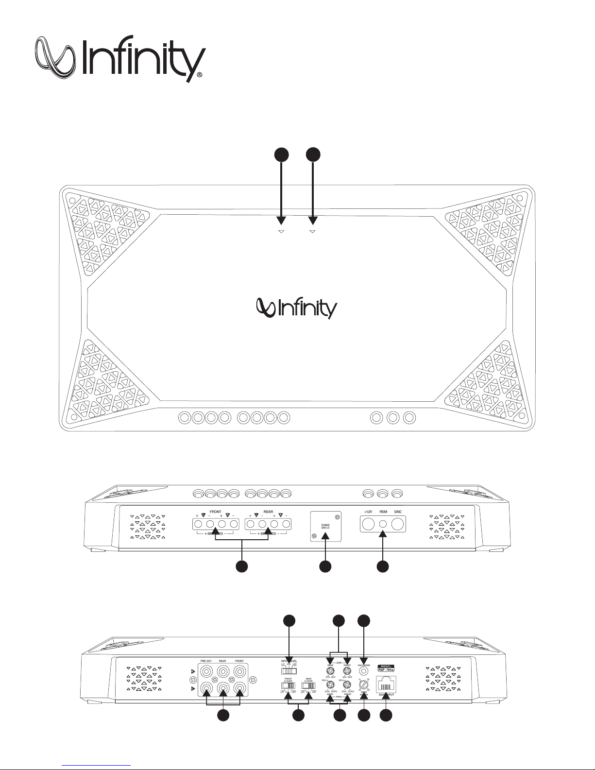
CHAPTER 1: PICTORIAL INDEX OF INPUT CONNECTIONS
REF Amplifier top panel
1
2
REF Amplifier front panel
POWE R
PROTEC T
REF Amplifier back panel
1
3
7
4 5
9
11
6 8 10 12 13
Page 5
INFINITY REFERENCE
CHAPTER 2: INSTALLATION AND WIRING
What's in the box:
1 amplifier
2 spare fuses (x3 with REF-4555a)
4 RCA adapters (x2 with REF-551a)
Quick-start guide
Precautions:
IMPORTANT: Disconnect the vehicle’s negative (–) battery terminal before beginning the installation.
• Always wear protective eyewear when using tools.
• Choose a safe mounting location, away from moisture. Check clearances on both sides of a planned mounting surface. Be sure that
screws or wires will not puncture brake lines, fuel lines, or wiring harnesses and that wire routing will not interfere with the safe
vehicle operation. Use caution when drilling or cutting in the mounting area.
• When making electrical connections, make sure they are secure and properly insulated.
• If you must replace any of the amplifier’s fuses, use the same type of fuse and current rating as the original.
• To keep the amplifier cool, choose a location that provides enough air circulation, such as under a seat or in the trunk.
• Do not mount the amplifier with the heat sink facing downward, as this interferes with cooling.
• Mount the amplifier so that it will not be damaged by the feet of backseat passengers or shifting cargo in the trunk, and so that it
remains dry.
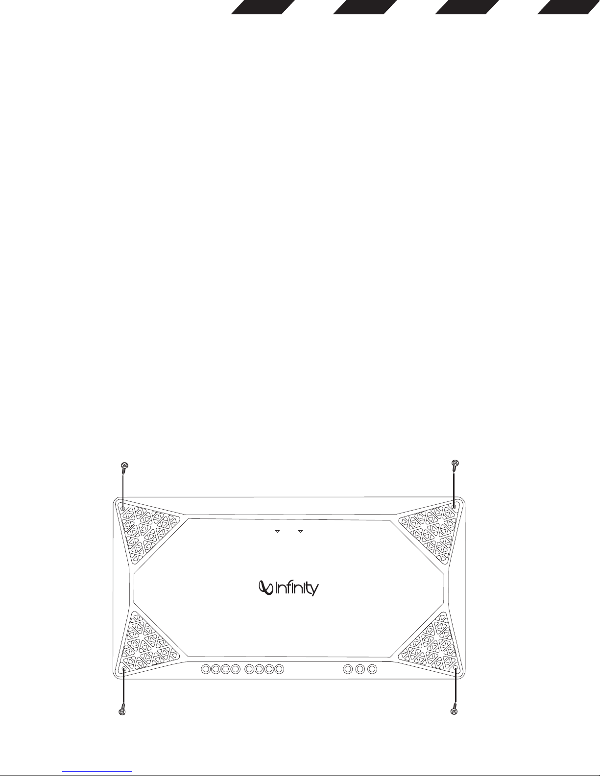
• Using the amplifier as a template, mark the locations of the holes on the mounting surface.
• Drill pilot holes in the mounting surface.
• Attach the amplifier to the mounting surface with four appropriate mounting screws (not included). Recommended: #8 Phillips-head
sheet metal screws.
NOTE: You may find it more convenient to make all of the connections to the amplifier before you permanently mount it.
POWER
PROTEC T
2
Page 6

1. Power indicator:
The light will illuminate in white when the amp is receiving power and playing.
2. Protect indicator:
The indicator will illuminate in red if the amp enters Protect mode in the event of conditions such as over/under voltage, short circuit, amplifier
output circuit failure, or excessive heat.
3. Speaker Output Connectors:
• Connect the speakers to these terminals, observing proper polarity (connect each speaker’s positive (+) lead to the appropriate positive
(+) terminal, and negative (-) lead to the appropriate negative (-) terminal.
• The REF-704a features Front L+, L-, R+, and R- terminals, and Rear L+, L-, R+, and R- terminals.
4-channel operation: Connect the front left speaker to the Front L+ and L- terminals, and the front right speaker to the Front
°
R+ and R- terminals. Connect the rear left speaker to the Rear L+ and L- terminals, and the rear right speaker to the Rear
R+ and R- terminals.
Left front speaker
Right front speaker
Left rear speaker
3
Right rear speaker
Page 7

INFINITY REFERENCE
3-channel operation: Connect the stereo speakers to the Front terminals, as described above. Connect the single speaker’s +
°
lead to the Rear L+ terminal, and the - lead to the Rear R- terminal.
Left front speaker Right front speaker
4-ohm subwoofer
2-channel (bridged) operation: Connect one speaker’s + lead to the Front L+ terminal, and the - lead to the Front R- terminal
°
Connect the other speaker’s + lead to the Rear L+ terminal, and the - lead to the Rear R- terminal.
4-ohm subwoofer4-ohm subwoofer
4
Page 8

• The REF-4555a features Front L+, L-, R+, and R- terminals; Rear L+, L-, R+, and R- terminals; and Sub + and - terminals.
5-channel operation: Connect the front left speaker to the Front L+ and L- terminals, and the front right speaker to the Front
°
R+ and R- terminals. Connect the rear left speaker to the Rear L+ and L- terminals, and the rear right speaker to the Rear R+
and R- terminals. Connect the subwoofer’s positive (+) lead to the + terminal, and the negative (-) lead to the - terminal.
4-ohm subwoofer
Left front speaker Right front speaker
Left rear speaker Right rear speaker
°
3-channel (front and rear bridged) operation: Connect one speaker’s + lead to the Front L+ terminal, and the - lead to the Front
R- terminal. Connect the other speaker’s + lead to the Rear L+ terminal, and the - lead to the Rear R- terminal. Connect the
subwoofer’s positive (+) lead to the + terminal, and the negative (-) lead to the – terminal.
4-ohm subwoofer
Front speaker
Rear speaker
5
Page 9

INFINITY REFERENCE
• The REF-551a features two positive (+) and two negative (-) terminals. To power two subwoofers in parallel, connect one sub’s positive
(+) and negative (-) leads to the positive and negative terminals on the left, and the other sub’s positive and negative leads to the positive
and negative terminals on the right. To power two subwoofers in series, connect one sub’s positive (+) lead to the positive terminal on
the left, and the other sub’s negative (-) lead to the negative terminal on the right, then connect left sub’s negative lead to the right sub’s
positive lead.
4-ohm subwoofer 4-ohm subwoofer
PARALLEL WIRING
2-ohm subwoofer
If you’re connecting only one sub, you can use either set of positive and negative terminals.
NOTE: Minimum speaker impedance for stereo full-range and subwoofer operation is 2ohms. Minimum speaker impedance for bridged operation
is 4ohms.
4. Fuses:
• Replace only with fuses of the same amperage:
° REF-704a, REF-551a: 30A
° REF-4555a: 30A
2-ohm subwoofer
SERIES WIRING
6
Page 10

5. Power Input Connectors:
• Power: Run power wire from the +12V input to the positive terminal of the vehicle’s battery. Install an appropriate fuse holder and fuse
(60A minimum on REF-704a and REF-551a, 105A minimum on REF-4555a) within 18” (457mm) of the battery. Make sure the wire is not
damaged or pinched during installation. Install protective grommets when routing wires through the bulkhead or other sheet metal. Use
larger-gauge wiring for longer runs.
° REF-704a minimum wire size: 10 gauge
° REF-4555a, REF-551a minimum wire size: 8 gauge
• Ground: Run a wire (the same gauge as the power wire) from the GND input to a factory bolt in the vehicle’s chassis (see illustration
below). NOTE: Remove any paint from the chassis for best contact. Use a star washer below the ring connector for a secure connection.
Factory Bolt
Factory Bolt
Ring Connector
Ring Connector
Ground Wire
Ground Wi re
Note: Remove any paint
Note: Remove any paint
below ring connector
below ring connector
Star Washer
Star Washer
• Remote: Connect a 20-gauge wire from the “Remote Out” lead of the source unit to the REM input. This lead turns the amplifier on when
using low-level input signals.
6. Front and rear inputs and outputs (RCA):
• If your source unit offers preamp outputs, connect to the FRONT, REAR, and/or SUB inputs using RCA patch cables.
•
To connect a second amp directly to the REF-704a amplifier, run a patch cable from the PRE OUT outputs to the second amp’s preamp inputs.
If your car audio system’s head unit does not have line-level outputs:
Use the supplied bare wire-to-RCA adapters to connect the REF amplifier’s inputs to either the front or the rear speaker outputs of your car audio
system’s head unit (splice crimps not included).
Important: Some factory-installed audio system amplifiers include electronic filters that limit the amount of bass sent to the system’s smaller
speakers. This filtering will adversely affect the REF amp’s performance. To get the most bass possible from your REF amp, splice the bare wire-toRCA adapters into the factory system speaker outputs that are connected to the system’s largest speakers (the ones designed to make the most bass).
Use a small phillips screwdriver to losen the adapter’s set screws and insert the speaker wires into the holes on the back of the adapter. Tighten
the set screws to secure the wires.
Loosen
Screws
7
Insert
Wires
Tighten
Screws
Page 11

INFINITY REFERENCE
Always connect the (+) speaker wire to the adapter’s (+) terminal and the (–) speaker wire to the adapter’s (–) terminal. When all wires are
connected, plug the adapters into the REF amplifier’s FRONT (and REAR, if using the 4-channel amplifier) preamp inputs.
PRE OUT REAR FRONT
From high-level
source
7. Input level:
Use this switch along with the gain control to set the REF amplifier’s input level. If using an aftermarket radio’s RCA-level outputs, set the Input
Level switch to the “LO” position. If using high-level outputs, start the control-setting process with the Input Level switch set in the “HI1” position.
Note: If you have connected your REF amplifier to a factory audio system’s speaker outputs, the audio signal may fail to play. If this happens,
change the Input Level switch to the “HI2” position. The “HI2” position includes a circuit designed to fool this type of factory audio system into
“seeing” a speaker connected to its input.
Important: The “HI2” setting should never be used when the REF amplifier is connected to an aftermarket head unit’s line-level (RCA-type)
outputs.
8. Crossover filter selectors (X-OVER):
Crossover-filter selectors (REF-704a and REF-4555a only; REF-551a filter is low pass only).
• LP: Low pass. Choose this setting if you’re connecting a subwoofer(s), or want to provide a low-pass filter for separate mid-bass speakers.
• FULL: Full range. Choose this setting if you’re connecting full-range speakers, and not using a subwoofer in your system.
• HP: High pass. Choose this setting to prevent low bass from reaching midrange or full-range speakers when you’re using a subwoofer in
your system.
(See Setting the crossovers in Chapter 4.)
9. Input level selectors (GAIN):
Input level controls. Use these to match the amp’s input sensitivity to the output level of your source unit. See 17 for a recommended adjustment
procedure.
(See Setting the input levels in Chapter 4 for a recommended adjustment procedure.)
8
Page 12

10. Crossover-filter frequency controls (FREQ):
Crossover-filter frequency controls. Turn the dials to the left to lower the crossover point, and to the right to raise the crossover point. Crossover
point settings vary by listener preference.
11. HALOsonic:
Lets you plug in an optional cable into your vehicle’s HALOsonic system (if present).
Also functions as a full-range mixing input.
12. ADAS ASSIGN (REF-704a and REF-4555a models only):
If you’ve connected the amp to an Advanced Driver Assistance System (see 13, next), this dial allows you to select the speaker over which you’ll
hear ADAS messages. Turn the dial to FL for the front left speaker, FR for the front right, RL for the rear left, and RR for the rear right.
13. ADAS INPUT (REF-704a and REF-4555a only):
Lets you plug a T568B cable (sold separately) from an optional Advanced Driver Assistance System into the amp’s RJ45 input jack. Also functions
as a priority switching input.
ADAS INPUT
T568B plug
T568B plug
When the system issues a warning or message, the amp will mute the music and play it over the speaker you’ve selected with the ADAS ASSIGN
dial (see 12, previous).
ADAS input channel sequence:
1. FL+ 2. FL- 3. FR+ 4. RL- 5. RL+ 6. FR- 7. RR+ 8. RR-
Four group signal: 1-2, 3-6, 5-4, 7-8
RJ45 input
1 2 3 4 5 6 7 8
T568B cable
1 2 3 4 5 6 7 8
9
Page 13

INFINITY REFERENCE
CHAPTER 3: OPERATIONS
Setting the input levels:
To match your amplifier’s input sensitivity (gain) to your source unit’s output level, we recommend the following procedure:
A. Turn both input level controls counterclockwise to MIN (minimum).
B. Play a dynamic music track through your source unit. Turn the source unit’s volume control to the 3/4 position.
C. Turn the front input level control dial clockwise towards MAX until you hear distortion in the music (it’s no longer clear).
D. Slowly turn the front level input control dial counterclockwise until the music sounds clear again.
E. Your front input level is now correctly set. Repeat this process with the rear channels.
A B C D E
Setting the crossover
Properly setting crossover filter selectors optimizes frequency distribution for efficient speaker operation and best sound.
Step 1: Use the slider controls to select low-pass (LP), FULL, or high-pass (HP).
• LP: Low pass. Choose this setting if you are connecting a subwoofer(s) or want to provide a low-pass filter for separate mid-bass speakers.
FULL: Full range. Choose this setting if you are connecting full-range speakers and are not using a subwoofer in your system.
• HP: High pass. Choose this setting to prevent low bass from reaching midrange or full-range speakers when you are using a subwoofer
in your system.
Step 2: Use crossover-filter frequency controls to adjust crossover point settings for coaxial speakers and subwoofers to suit listener preference.
Turn the dials to the left to lower the crossover point and to the right to raise the crossover point. Exact crossover settings for coaxial speakers
and subwoofers finally depend on your listening preferences. NOTE: crossover point does not apply in FULL mode.
Adjusting the subwoofer:
Select INT if you’re connecting a subwoofer to the REF-4555a amplifier, but your source unit
a summed audio signal to the subwoofer). If your source unit
does
feature a subwoofer output, select EXT to connect to that output.
does not
feature a subwoofer output (this will send
SUB INPUT
INT EXT
10
Page 14

Selecting the subwoofer phase
You can choose a subwoofer phase output of 0° or 180°. To check your sub's phase, play music with lots of bass and listen as another person
slowly flips the 0/180 degree phase switch back and forth. The correct setting is the one that gives you more bass. If you don't detect any real
difference, leave the switch in the 0 setting.
PHASE
0º 180º
Boosting the bass
Turn the dial lockwise to increase the bass output from 0 dB to +9 dB.
BASS BOOST
••
0dB
+9dB
CHAPTER 4: TROUBLESHOOTING
PROBLEM: No audio and POWER INDICATOR is off.
CAUSE and SOLUTION: No voltage at BATT+ and/or REM terminals, or bad or no ground connection. Check voltages at amplifier terminals
with VOM.
PROBLEM: No audio and PROTECT INDICATOR flashes every 4 seconds.
CAUSE and SOLUTION: DC voltage on amplifier output. Amplifier may need service; see enclosed warranty card for service information.
PROBLEM: No audio and PROTECT INDICATOR is on.
CAUSE and SOLUTION: Amplifier is overheated. Make sure amplifier cooling is not blocked at mounting location. Verify that speaker-system
impedance is within specified limits. Or, there may be voltage greater than 16V (or less than 8.5V) on BATT+ connection. Check vehicle
charging system.
PROBLEM: No audio and PROTECT and POWER INDICATORS flash.
CAUSE and SOLUTION: Voltage less than 9V on BATT+ connection. Check vehicle charging system.
PROBLEM: Distorted audio.
CAUSE and SOLUTION: Gain is not set properly. Check INPUT LEVEL setting. Check speaker wires for shorts or grounds. Amplifier or source unit
may be defective.
PROBLEM: Distorted audio and PROTECT INDICATOR flashes.
CAUSE and SOLUTION: Short circuit in speaker or wire. Remove speaker leads one at a time to locate shorted speaker or wire, and repair.
11
Page 15

INFINITY REFERENCE
PROBLEM: Music lacks dynamics or "punch."
CAUSE and SOLUTION: Speakers are not connected properly. Check speaker connections for proper polarity.
PROBLEM: Amplifier fuse keeps blowing.
CAUSE and PROBLEM: The wiring is connected incorrectly or there is a short circuit. Review installation precautions and procedures in manual.
Check wiring connections.
PROBLEM: Engine noise—whining or clicking—in system when the engine is on.
CAUSE and PROBLEM: Amplifier is picking up alternator noise. Turn down gain. Move audio cables away from power wires. Install an alternator
noise filter on power line between battery and alternator. Check ground connections on the amplifier since a loose or improper ground is one
of the main causes for extraneous noise in your audio system.
CHAPTER 5: SPECIFICATIONS
Model
REF-704a 70W x 4 100W x 4 200W x 2 1000W 10Hz-40kHz 20V 200mV
REF-4555a
REF-551a 370W x 1 550W x 1 / 1300W 10Hz-320Hz 20V 200mV
RMS power
@ 4 ohms
45W x 4 65W x 4 130W x 2
320W x 1 500W x 1 / 10Hz-320Hz (sub)
RMS power
@ 2 ohms
RMS bridged power
@ 4 ohms
Total peak
power
1800W
Frequency
response
10Hz-40kHz
(full range)
Maximum
signal input
20V 200mV
Model
REF-704a ≥85dB ≤1%
REF-4555a
REF-551a ≥80dB ≤1%
Line in signal-to-noise ratio
(reference to 1 watt)
Full:≥85dB
Sub:≥80dB
THD+ N at rated power
(20Hz – 20kHz)
≤1%
Product dimensions
(L x W x D)
358 x 185.5 x 55.75 mm
14-1/8" x 7-5/16" x 2-1/4"
398 x 185.5 x 55.75mm
15-11/16" x 7-5/16" x 2-1/4"
238 x 185.5 x 55.75mm
9-3/8" x 7-5/16" x 2-1/4"
Shipping weight (kg) Fuse size
4.33kg
(9.5lbs)
3.26kg
(7.2lbs)
5.01kg
(11.0lbs)
30A x 2 9-16VDC
30A x 3 9-16VDC
30A x 2 9-16VDC
Maximum
sensitivity
Operating
voltage
12
Page 16

HARMAN International Industries, Inc.
8500 Balboa Boulevard, Northridge, CA 91329 USA
www.infinityspeakers.com
© 2016 HARMAN International Industries, Incorporated. All rights reserved. Infinity is a trademark of
HARMAN International Industries, Incorporated, registered in the United States and/or other countries.
The Bluetooth® word mark and logos are registered trademarks owned by Bluetooth SIG, Inc. and any
use of such marks by HARMAN International Industries, Incorporated is under license. Other trademarks
and trade names are those of their respective owners. Features, specifications and appearance are
subject to change without notice.
TR02575_A
 Loading...