

Page 1

935-CK804A-000
87100523
System Board User’s Manual
Carte Mère Manuel Pour Utilisateur
System-Platine Benutzerhandbuch
Manual del Usuario de Placas Base
Руководство ПользователяРуководство Пользователя
Руководство ПользователяРуководство Пользователя
Руководство Пользователя
Page 2

2
Quick Setup Guide
1
Quick Setup
Guide
Copyright
This publication contains information that is protected by copyright. No part of it
may be reproduced in any form or by any means or used to make any
transformation/adaptation without the prior written permission from the copyright
holders. This publication is provided for informational purposes only. The
manufacturer makes no representations or warranties with respect to the
contents or use of this manual and specifically disclaims any express or implied
warranties of merchantability or fitness for any particular purpose. The user will
assume the entire risk of the use or the results of the use of this document.
Further, the manufacturer reserves the right to revise this publication and make
changes to its contents at any time, without obligation to notify any person or
entity of such revisions or changes. © 2005. All Rights Reserved.
Trademarks
Product names or trademarks appearing in this manual are for identification
purpose only and are the properties of the respective owners.
Caution
To avoid damage to the system, use the correct AC input voltage range
..
..
.
To reduce the risk of electric shock, unplug the power cord before removing the
system chassis cover for installation or servicing. After installation or servicing,
cover the system chassis before plugging the power cord.
Battery: 1. Danger of explosion if battery incorrectly replaced. 2. Replace only
with the same or equivalent type recommend
by the manufacturer. 3. Dispose of
used batteries according to the battery manufacturer’s
instructions.
Notice
The system board and accessories in the package may not come similar to the
information stated in this manual. This may differ in accordance to the sales region
or models in which it was sold. For more information about the standard
package in your region, please contact your dealer or sales representative.
FCC and DOC Statement on Class B
This equipment has been tested and found to comply with the limits for a Class
B digital device, pursuant to Part 15 of the FCC rules. These limits are designed
to provide reasonable protection against harmful interference when the
equipment is operated in a residential installation. This equipment generates, uses
and can radiate radio frequency energy and, if not installed and used in accordance with the instruction manual, may cause harmful interference to radio
communications. However, there is no guarantee that interference will not occur
in a particular installation. If this equipment does cause harmful interference to
radio or television reception, which can be determined by turning the equipment
off and on, the user is encouraged to try to correct the interference by one or
more of the following measures:
• Reorient or relocate the receiving antenna.
• Increase the separation between the equipment and the receiver.
• Connect the equipment into an outlet on a circuit different from that to
which the receiver is connected.
• Consult the dealer or an experienced radio TV technician for help.
Notice:
1. The changes or modifications not expressly approved by the party
responsible for compliance could void the user's authority to operate the
equipment.
2. Shielded interface cables must be used in order to comply with the emission
limits.
Page 3

3
1
Quick Setup Guide
Quick Setup
Guide
Table of Contents
Chapter 1
Quick Setup Guide.............................................
Chapter 2
English......................................................................
Chapter 3
Français....................................................................
Chapter 4
Deutsch...............................................................................
Chapter 5
Español............................................................................
Chapter 6
Русский.......................................................................
4
17
21
25
29
33
The user’s manual in the provided CD contains detailed information about the system board. If, in some
cases, some information doesn’t match those shown in this manual, this manual should always be regarded as the most updated version.
Le manuel d’utilisateur dans le CD muni contient renseignement détaillé au sujet de carte de système. Si,
en quelque cas, quelque renseignement n’appareille de ce que dit dans ce manuel, ce manuel doit
toujours être considéré comme la plus nouvelle version.
Das Benutzerhandbuch in der angebotenen CD enthält detaillierte Informationen über die Hauptplatine.
Wenn in manchen Fällen manche Informationen nicht denjenigen Informationen dargestellt in diesem
Handbuch entsprechen, soll dieses Handbuch als die meist aktualisier te Ausgabe gelten.
El uso explicativo contene información detalle sobre la sistema board en el CD preparativo. Si en algún
caso, la información no es igual con el uso explicativo, necesita ver el uso explicativo, esque es más
nuevo.
В руководстве пользователя на предоставляемом CD диске содержится подробная
информация о материнской плате. Иногда напечатанное руководство может не
совпадать руководством на CD, так как последнее наиболее часто обновляется и
является самым свежим.
Page 4

4
Quick Setup Guide
1
Quick Setup
Guide
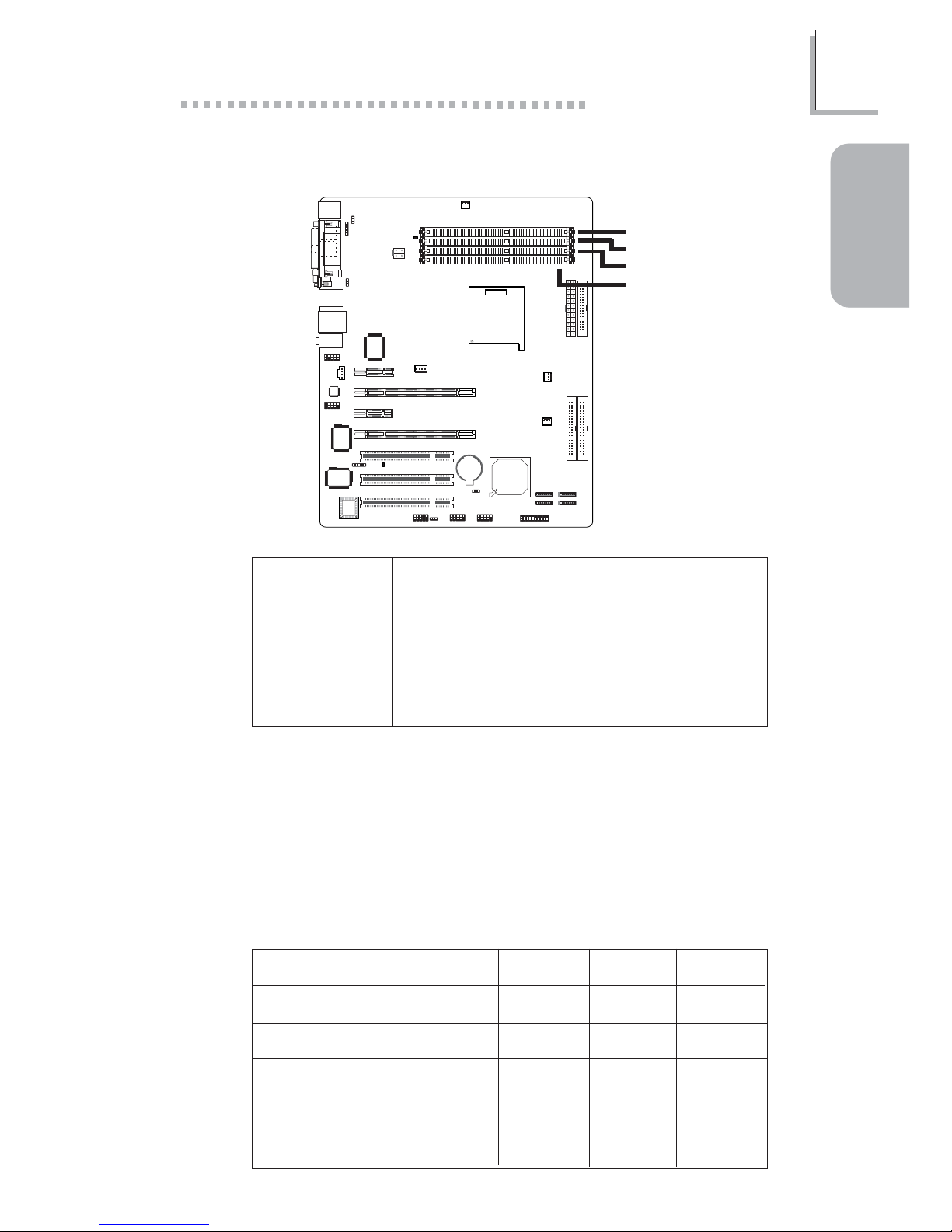
System Board Layout
Chapter 1 - Quick Setup Guide
Page 5
5
1
Quick Setup Guide
Quick Setup
Guide
System Memory
• DIMMs are on the same channel.
• DIMMs in a channel can be identical or
completely different. However, we highly
recommend using identical DIMMs.
• Not all slots need to be populated.
• DIMMs of the same memory configura-
tion are on different channels.
Single Channel
Dual Channel
Memory Configurations
The table below shows the DIMM sockets that must be populated
with DIMMs for single or dual channel interface. We strongly
recommend that you strictly follow the memory configurations below.
Installing DDR DIMMs other than the recommended configurations
may cause system boot failure.
DDR 1
-
DDR 1
DDR 1
-
DDR 1
Dual Channel
Dual Channel
Dual Channel
Single Channel
Single Channel
Single Channel
DDR 2
-
DDR 2
-
-
-
-
DDR 3
DDR 3
-
DDR 3
DDR 3
-
DDR 4
DDR 4
-
-
-
DDR 4 Channel B
DDR 3 Channel A
DDR 2 Channel B
DDR 1 Channel A
Page 6
6
Quick Setup Guide
1
Quick Setup
Guide
Important Notes on Memory Usage
1. The system board will fail to boot when 3 DIMMs are used.
The integrated memory controller in AMD's 64-bit Socket 939
series CPU supports dual channel however when 3 DIMMs are
installed, the controller is not capable of accurately distinguishing
between dual and single channels resulting to boot up problem.
Even if you have luckily booted the system, the total memory
size detected is from 2 DIMMs only, not 3. Therefore we do not
suggest using 3 DIMMs.
Memory Speed
DDR400
DDR400
DDR400
DDR400
DDR400
DDR333
DDR400
DDR400
DDR400
DDR333
DIMM 1
S
D
S
D
S
D
S
D
DIMM 2
S
D
S
D
DIMM 3
S
D
S
D
S
D
DIMM 4
S
D
"S": Single side DIMM
"D": Double side DIMM
2. The table below lists different memory configurations and their
corresponding memory speed. Take note that some memory
configurations will automatically reduce the memory speed to
DDR333.
If in any case the system becomes unstable, set the memory
timing from “1T” to “2T” in the “1T/2T Memory Timing” field
(Genie BIOS Setting submenu of the Award BIOS).
Page 7
7
1
Quick Setup Guide
Quick Setup
Guide
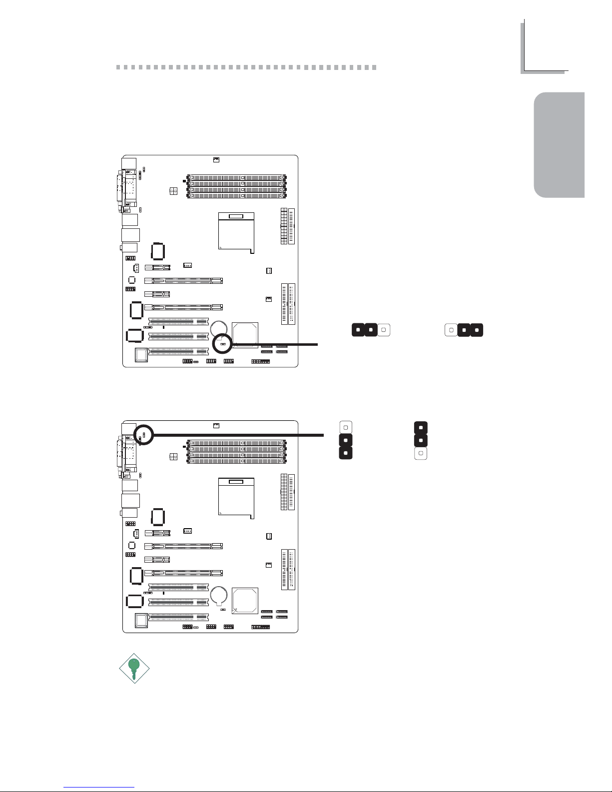
Jumpers
Important:
The 5VSB power source of your power supply must support
≥
720mA.
Clear CMOS Data
PS/2 Power Select
2-3 On:
Clear CMOS Data
1-2 On: Normal
(default)
X
JP2
312312
X
JP7 3
1
2
3
1
2
2-3 On: 5VSB
1-2 On: 5V
(default)
Page 8
8
Quick Setup Guide
1
Quick Setup
Guide
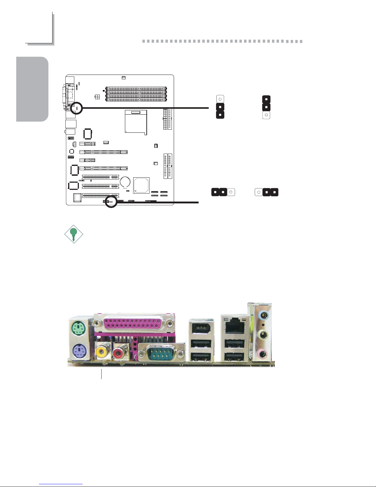
Important:
If you are using the Wake-On-USB Keyboard/Mouse function for 2
USB ports, the 5VSB power source of your power supply must
support ≥1.5A. For 3 or more USB ports, the 5VSB power source of
your power supply must support ≥2A.
USB Power Select
Rear Panel I/O Ports
X
USB 1-4
(JP5)
3
1
2
3
1
2
2-3 On: 5VSB1-2 On: 5V
(default)
2-3 On: 5VSB
1-2 On: 5V
(default)
X
USB 5-10
(JP6)
312312
PS/2
Mouse
PS/2
K/B
COM
S/PDIF-out
S/PDIF-in USB 1-2 USB 3-4
1394_1
LAN
Parallel
Line-out
Line-in
Mic-in
Page 9
9
1
Quick Setup Guide
Quick Setup
Guide
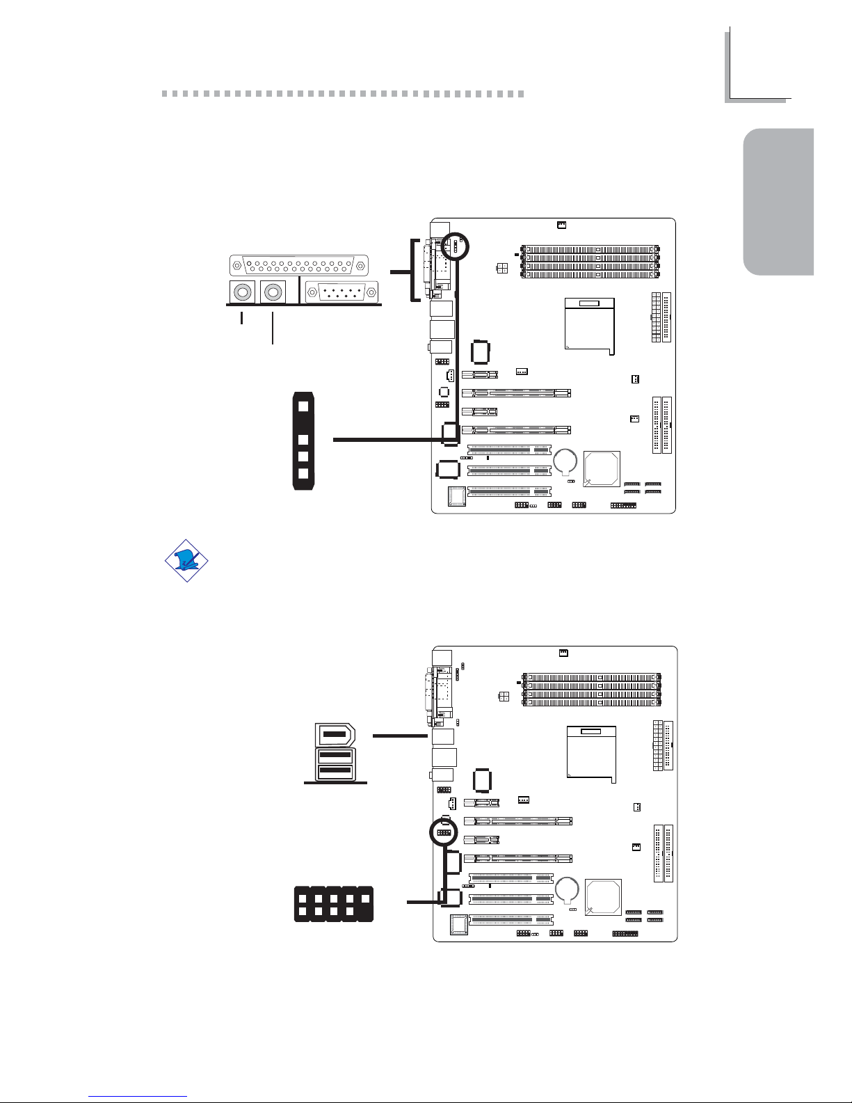
I/O Connectors
Note:
DO NOT use RCA S/PDIF and optical S/PDIF at the same time.
S/PDIF-in/out Jacks
W
J3
1
5
+5V
Key
SPDIF out
SPDIF in
GND
S/PDIF-out
S/PDIF-in
W
IEEE 1394
1394_1
W
W
1394_2
+12V (fused)
1
TPA+
Ground
TPB+
+12V (fused)
Key
TPA-
Ground
TPB-
Ground
2
10
9
Page 10
10
Quick Setup Guide
1
Quick Setup
Guide
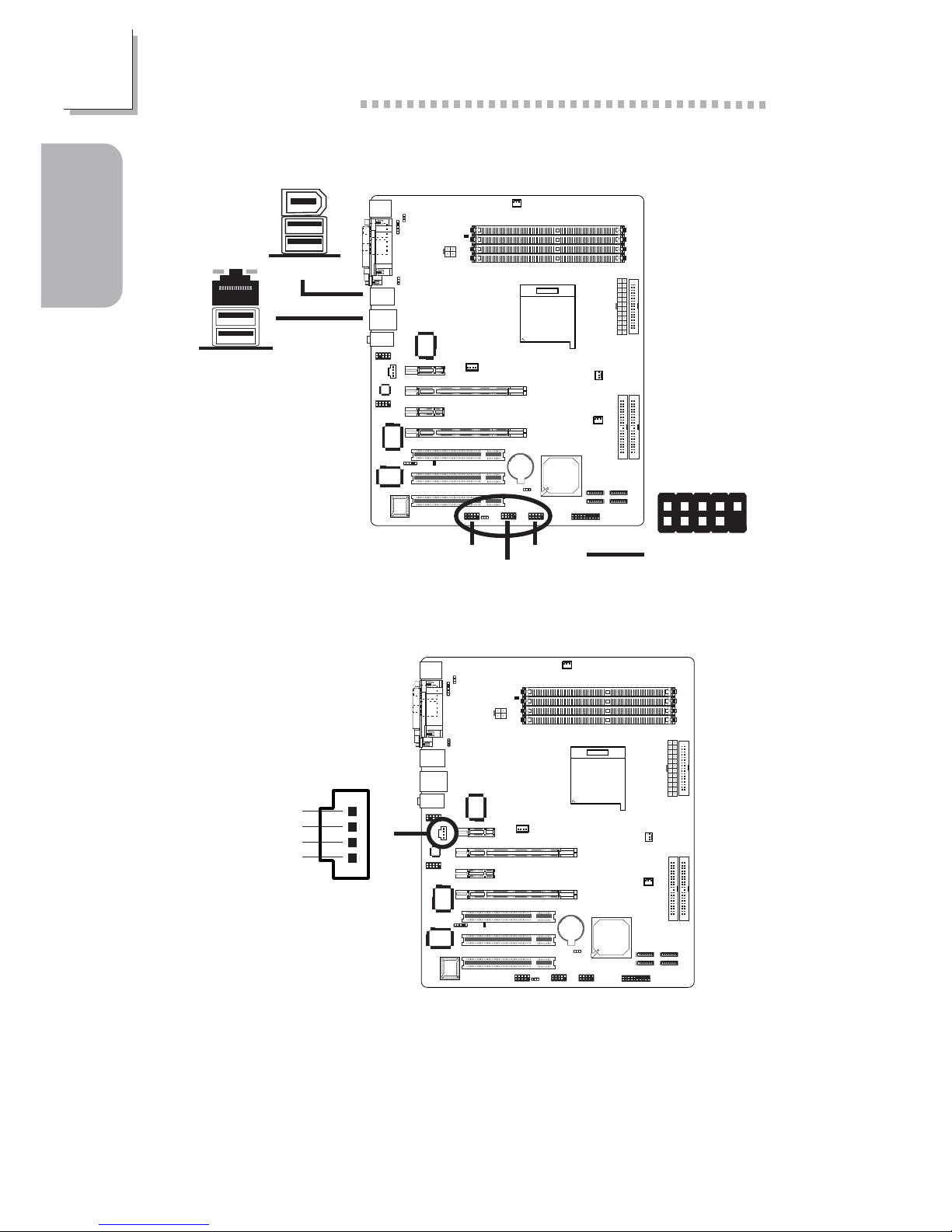
USB 4
USB 3
Universal Serial Bus Ports
W
USB 2
USB 1
USB 5-6
W
USB 7-8
W
USB 9-10
1
VCC
-Data
+Data
Ground
Key
VCC
-Data
+Data
Ground
N. C.
2
10
9
CD-in Internal Audio Connector
W
1
4
Right audio
channel
Left audio
channel
Ground
Ground
Page 11
11
1
Quick Setup Guide
Quick Setup
Guide
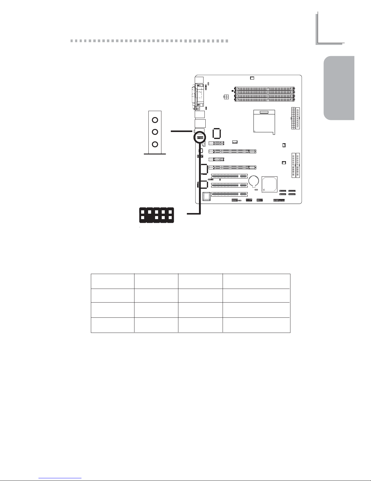
Front audio W
Audio (Rear Audio and Front Audio)
Mic-in
Line-out
Line-in
W
Rear audio
1
2
10
9
MicGND
Mic Power
AuD_Vcc
AuD_R_Out
AuD_R_Return
N. C.
Key
AuD_L_Out
AuD_L_Return
Light Blue
Lime
Pink
2-channel
Line-in
Line-out
Mic-in
4-channel
Rear R/L
Front R/L
Mic-in
6-channel
Rear R/L
Front R/L
Center/Subwoofer
Page 12

12
Quick Setup Guide
1
Quick Setup
Guide
Important:
Before creating RAID, make sure you have installed the Serial/Parallel
ATA drives and connected the data cables otherwise you won’t be
able to enter the NVIDIA RAID BIOS utility.
Floppy Disk Drive Connector
X
34
33
21
Serial ATA Connectors
X
SATA 3 (J2)
17
SATA 4 (J10)
17
SATA 2 (J11)
17
SATA 1 (J13)
17
Page 13

13
1
Quick Setup Guide
Quick Setup
Guide
IDE Disk Drive Connector
X
40
39
21
IDE 2
40
39
21
IDE 1
Important:
Before creating RAID, make sure you have installed the Serial/Parallel
ATA drives and connected the data cables otherwise you won’t be
able to enter the NVIDIA RAID BIOS utility.
Cooling Fan Connectors
X
X
X
CPU fan
1
3
Ground
Power
Sense
System fan
Chipset fan
31
Ground
Power
Sense
31
Ground
Power
Sense
Page 14

14
Quick Setup Guide
1
Quick Setup
Guide
Note:
The sequence of the pin functions on some IR cable may be
reversed from the pin function defined on the system board. Make
sure to connect the cable connector to the IR connector according to
their pin functions.
IrDA Connector
W
51
VCC
N. C.
IRRX
Ground
IRTX
LEDs
Standby
Power LED
DRAM
Power LED
Page 15

15
1
Quick Setup Guide
Quick Setup
Guide
Important:
To ensure that adequate power is provided, we strongly recommend
that you use a minimum of 400 Watt (or greater) power supply.
Power Connectors
X
X
4
3
1
2
+12V
Ground
Ground
+12V
13 1
1224
+3.3VDC
+3.3VDC
COM
+5VDC
COM
+5VDC
COM
PWR_OK
+5VSB
+12VDC
+12VDC
+3.3VDC
+3.3VDC
-12VDC
COM
PS_ON#
COM
COM
COM
NC
+5VDC
+5VDC
+5VDC
COM
5V/12V
1
4
+5V+12V
Ground
Ground
X
PCI Express Slots
PCI Express x16
PCI Express x1
PCI Express x1
PCI Express x16
Page 16

16
Quick Setup Guide
1
Quick Setup
Guide
Front Panel Connectors
X
J19
1
2
19
20
HD-LED
PWR-LED
ATX-SW
RESET
SPEAKER
Pin
3
5
14
16
8
10
18
20
7
9
13
15
17
19
2
4
6
HD-LED
(Primary/Secondary IDE LED)
Reserved
ATX-SW
(ATX power switch)
Reserved
RESET
(Reset switch)
SPEAKER
(Speaker connector)
PWR-LED
(Power/Standby LED)
Pin Assignment
HDD LED Power
HDD
N. C.
N. C.
PWRBT+
PWRBT-
N. C.
N. C.
Ground
H/W Reset
Speaker Data
N. C.
Ground
Speaker Power
LED Power (+)
LED Power (+)
LED Power (-) or Standby Signal
Page 17

17
2
English
English
Chapter 2 - English
Features and Specifications
Processor
• AMD AthlonTM 64 FX / AthlonTM 64 / Sempron
TM
• 2000MT/s HyperTransport interface
• Socket 939
Chipset
• NVIDIA nForce4TM SLI
- Supports NVIDIA SLITM (Scalable Link Interface)
System Memory
• Four 184-pin DDR SDRAM DIMM sockets
• Supports dual channel (128-bit wide) memory interface
• Supports up to 4GB system memory
• Supports PC2100 (DDR266), PC2700 (DDR333) and PC3200
(DDR400) DDR SDRAM DIMM
• Supports x8/x16 ECC/non-ECC unbuffered DIMMs, up to
512Mb DDR devices
Expansion Slots
• 2 PCI Express x16 slots (operates at x8 bandwidth)
• 2 PCI Express x1 slots
• 3 PCI slots
SLI (Scalable Link Interface) Mode
• Use 2 SLI-ready PCI Express x16 graphics cards (use identical
cards) on the PCI Express x16 slots.
• In SLI mode, the bandwidth of each x16 slot works at the
bandwidth of x8. When the graphics cards are connected via the
SLI bridge, it runs at x16 bandwidth.
BIOS
• Award BIOS
• 4Mbit flash memory
Energy Efficient Design
• Supports ACPI specification and OS Directed Power
Management
• Supports ACPI STR (Suspend to RAM) function
Page 18

18
English
2
English
• Wake-On-Events include:
- Wake-On-PS/2 Keyboard/Mouse
- Wake-On-USB Keyboard/Mouse
- Wake-On-LAN
- Wake-On-Ring
- RTC timer to power-on the system
• AC power failure recovery
Hardware Monitor
• Monitors CPU/system temperature
• Monitors VCC3/12V/3.3V/5VSB/Vbat voltages
• Monitors the speed of the cooling fans
• CPU Overheat Protection function monitors CPU temperature
during system boot-up
Onboard Audio Features
• 6-channel audio CODEC
• True stereo line level outputs
• S/PDIF-in/out interface
Onboard LAN Features
• Marvell 88E1111 Gigabit Phy
• Fully compliant to IEEE 802.3 (10BASE-T), 802.3u (100BASE-TX)
and 802.3ab (1000BASE-T) standards
• Integrated power management functions
• Supports wire for management
IDE Interface with NVIDIA RAID
• Supports two IDE connectors that allow connecting up to four
UltraDMA 133Mbps hard drives
• NVIDIA RAID allows RAID arrays spanning across Serial ATA
and Parallel ATA
• RAID 0, RAID 1, RAID 0+1 and JBOD
Serial ATA Interface with NVIDIA RAID
• Supports four Serial ATA ports
• SATA speed up to 3Gb/s
• NVIDIA RAID allows RAID arrays spanning across Serial ATA
and Parallel ATA
• RAID 0, RAID 1, RAID 0+1 and JBOD
Page 19

19
2
English
English
IEEE 1394 Interface
• VIA VT6307
• Supports two 100/200/400 Mb/sec ports
Rear Panel I/O Ports
• 1 mini-DIN-6 PS/2 mouse port
• 1 mini-DIN-6 PS/2 keyboard port
• 2 S/PDIF RCA jacks (S/PDIF-in and S/PDIF-out)
• 1 parallel port
• 1 serial port
• 1 IEEE 1394 port
• 1 RJ45 LAN port
• 4 USB 2.0/1.1 ports
• Line-in, line-out and mic-in jacks
I/O Connectors
• 3 connectors for 6 additional external USB 2.0/1.1 ports
• 1 connector for 1 external IEEE 1394 port
• 1 front audio connector for external line-out and mic-in jacks
• 1 CD-in internal audio connector
• 1 S/PDIF connector for optical cable connection
• 1 IrDA connector
• 4 Serial ATA connectors
• 2 IDE connectors
• 1 floppy connector
• 1 24-pin ATX power connector
• 1 4-pin ATX 12V power connector
• 1 5V/12V power connector
• 1 front panel connector
• 3 fan connectors
PCB
• ATX form factor
• 24.4cm (9.6") x 30.5cm (12")
Page 20

20
English
2
English
Package Checklist
The system board package contains the following items:
; The system board
; A user’s manual
; One IDE cable
; One floppy cable
; Two Serial ATA data cables
; One Serial ATA power cable
; One “nVRAID Driver” diskette
; One I/O shield
; One “Mainboard Utility” CD
If any of these items are missing or damaged, please contact your
dealer or sales representative for assistance.
Page 21

21
3
Français
Français
Chapter 3 - Français
Caractéristiques et Spécifications
Processeur
• AMD AthlonTM 64 FX / AthlonTM 64 / Sempron
TM
• Interface HyperTransport 2000MT/s
• Socket 939
Chipset
• NVIDIA nForce4TM SLI
- Supporte NVIDIA SLITM (Scalable Link Interface)
Mémoire Système
• 4 sockets DDR SDRAM DIMM 184 broches
• Supporte l’interface de mémoire deux canaux (128-bit)
• Supporte jusqu’à 4GB de mémoire
• Supporte DDR SDRAM DIMM PC2100 (DDR266), PC2700
(DDR333) et PC3200 (DDR400)
• Supporte exclusivement les modules DIMM ECC/non-ECC x8/
x16, densité de RAM jusqu’à 512Mb, DIMM non-tamponnés
Logements d’Extension
• 2 slots PCI Express x16 (la bande passante est de x8)
• 2 slots PCI Express x1
• 3 slots PCI
Mode SLI
• 2 cartes graphiques SLI-ready (utiliser des cartes identiques) sur
les bus PCI Express x16.
• La bande passante de chaque encoche est x8; Lorsque les
cartes graphiques sont connectées via le pont SLI, la bande
passante est de x16.
BIOS
• Compatible avec Award BIOS
• Mémoire Flash 4Mbit
Page 22

22
Français
3
Français
Français
Design à Haut Rendement Énergétique
• ACPI STR (Suspend to RAM) fonction
• Réveil-Sur-PS/2 Clavier/Souris
• Réveil-Sur-USB Clavier/Souris
• Eveil Sonnerie
• Réveil Par Le Réseau
• Minuterie RTC pour allumer le système
• Récupération après Défaillance d’Alimentation CA
System Health Monitor Fonctions
• Gère l’alarme de température et de surchauffe de CPU/système
• Gère l’alarme de voltage et d’échec de VCC3/12V/3.3V/5VSB/
Vbat
• Gère la vitesse de ventilateur du ventilateurs
• Protection du CPU - supporte la mise hors circuit automatique
en cas de surchauffage du système
Caractéristiques Audio sur Carte
• 6-canaux audio CODEC
• Sorties de niveau de lignes stéréo vraies
• Interface entrée/sortie S/PDIF
Fonctionnalités Onboard LAN
• Marvell 88E1111 Gigabit Phy
• Supporte IEEE 802.3 (10BASE-T), 802.3u (100BASE-TX) et
802.3ab (1000BASE-T)
• Fonctions de gestion d’alimentation intégrées
• Support câble pour la gestion
Interface IDE avec NVIDIA RAID
• Deux connecteurs IDE permettant de connecter jusqu’à quatre
disques durs UltraDMA 133Mbps.
• NVIDIA RAID permet des ensembles RAID sur toute l’étendue
du port de série ATA et du parallèle ATA
• RAID 0, RAID 1, RAID 0+1 et JBOD
Interface Série ATA avec NVIDIA RAID
• Quatre ports de série ATA
• Vitesse SATA jusqu’à 3Gb/s
• NVIDIA RAID permet des ensembles RAID sur toute l’étendue
du port de série ATA et du parallèle ATA
• RAID 0, RAID 1, RAID 0+1 et JBOD
Page 23

23
3
Français
Français
Interface IEEE 1394
• VIA VT6307
• Supporte 2 ports 100/200/400 Mb/séc
Le Panneau des Ports Entrée/Sortie en Arrière
• 1 port souris PS/2
• 1 port clavier PS/2
• 2 S/PDIF RCA prises (S/PDIF-out et S/PDIF-in)
• 1 port parallèle DB-25
• 1 port de DB-9 série
• 1 port IEEE 1394
• 1 port RJ45 LAN
• 4 ports USB 2.0/1.1
• Line-in, line-out et mic-in prises audio
Connecteurs Entrée/Sortie
• 3 connecteurs pour 6 ports USB 2.0/1.1 supplémentaires
• 1 connecteur pour 1 IEEE 1394
• 1 connecteur audio frontal pour les jacks de sortie externe et
d’entrée micro
•1 connecteur CD-in audio internes
• 1 S/PDIF l’assemblage pour l’adjonction de câble optique
• 1 connecteur IR
•4 connecteurs Serial ATA
• 2 connecteurs IDE
• 1 connecteur de FDD
• 1 connecteur d’alimentation 24-pin ATX
• 1 connecteur d’alimentation 4-pin 12V ATX
• 1 connecteur d’alimentation 5V/12V
• 1 connecteur devant panneau
• 3 connecteurs de ventilateurs
PCB
•ATX
• 24.4cm (9.6") x 30.5cm (12")
Page 24

24
Français
3
Français
Français
Liste de Vérification de l’Emballage
L’emballage de la carte système contient les éléments suivants:
; 1 carte système
; 1 manuel utilisateur
; 1 câble IDE
; 1 câble floppy
; 2 câble SATA
; 1 câble d’alimentation SATA
; 1 disquette “nVRAID Driver”
; 1 shield I/O
; 1 CD “Mainboard Utility”
Si l’un de ces éléments n’était pas dans l’emballage ou s’il était
endommagé, veuillez contacter votre revendeur ou votre
représentant.
Page 25

25
4
Deutsch
Deutsch
Chapter 4 - Deutsch
Leistungsmerkmale und Technische Daten
Prozessor
• AMD AthlonTM 64 FX / AthlonTM 64 / Sempron
TM
• Interface HyperTransport 2000MT/s
• Socket 939
Chipset
• NVIDIA nForce4TM SLI
- Unterhält NVIDIA SLITM (Scalable Link Interface)
Systemspeicher
• 4 DDR-SDRAM-DIMM- Fassungen mit 184poligem
Anschlußstecker
• Unterhält 128-bit – Speiher mit den zwei Kanälen
• Unterhält bis zum 4GB-Systemspeicher
• Unterstützt DDR SDRAM DIMM PC2100 (DDR266), PC2700
(DDR333) und PC3200 (DDR400)
• Unterhält nur ECC/non-ECC x8/x16 DIMMs, ohne Dämpfer, bis
zum 512Mb DRAM
Erweiterungssteckfasssungen
• 2 PCI Express x16-Einbauplätzen (beträgt die Bandbreite x8)
• 2 PCI Express x1-Einbauplätzen
• 3 PCI-Einbauplätzen
SLI-Modus
• 2 SLI-kompatible Grafikkarten (bitte identische Karten
verwenden) in den Steckplätzen für PCI Express x16
• Die Bandbreite der Steckplätze beträgt jeweils x8; wenn die
Grafikkarten per SLI-Verbindung angeschlossen sind, beträgt die
Bandbreite x16.
BIOS
• Kompatibilität mit Award BIOS
• Flash-Speicher (4Mbit)
Page 26

26
Français
4
Deutsch
Deutsch
Energomisches Design
• ACPI STR (Suspend to RAM) funktion
• Wecken bei Betätigung der PS/2 Tastatur/Maus
• Wecken bei USB-Tastatur/Maus
• Wecken bei Klingeln
• Wecken des Systems durch das Netzwerk
• RTC-Taktgeber zum Einschalten des Systems
• Wiederherstellung der Wechselstromversorgung nach einem
Ausfall
System Health Monitor Funktions
• Überwachung der Temperatur des CPU/Systems sowie
Warnsignal bei Überhitzung
• Überwachung der Spannungen des VCC3/12V/3.3V/5VSB/Vbat
• Überwachung der Geschwindigkeit des Ventilators
• Prozessor-Shutz - Die Ausschaltung bei der Überhitzung – die
automatische Ausschaltung des Computers bei der Überhitzung
Audiomerkmale auf Platine
• 6-Kanal-Audio-CODEC
• Naturgetreue Stereo-Leitungspegel-Ausgabe
• S/PDIF-In/Aus-Schnittstelle
Merkmale des LAN auf Platine
• Marvell 88E1111 Gigabit Phy
• Unterstützt IEEE 802.3 (10BASE-T), 802.3u (100BASE-TX) und
802.3ab (1000BASE-T)
• Integrierte Power-Management-Funktionen
• Unterstützung des Leiters für das Management
IDE-Schnittstelle mit NVIDIA RAID
• Zwei IDE-Schnittstellen, an denen bis zu vier UltraDMA 133Mbps
Festplatten angeschlossen werden können.
• NVIDIA RAID ermöglicht, dass die RAID-Arrays sowohl serielle
als auch parallele ATA-Schnittstellen umfassen.
• RAID 0, RAID 1, RAID 0+1 und JBOD
Page 27

27
4
Deutsch
Deutsch
Serielle ATA-Schnittstelle mit NVIDIA RAID
• 4 Serial ATA-Ports
• SATA bis zu 3Gb/s schnell
• NVIDIA RAID ermöglicht, dass die RAID-Arrays sowohl serielle
als auch parallele ATA-Schnittstellen umfassen
• RAID 0, RAID 1, RAID 0+1 und JBOD
IEEE 1394 Schnittstelle
• VIA VT6307
• Uunterstützt 2 Ports 100/200/400 Mbps
Ein-/Ausgabe-Porte an der Rückwand
• 1 Mini-DIN-6-Anschluß für eine PS/2-Maus
• 1 Mini-DIN-6-Anschluß für eine PS/2-Tastatur
• 2 S/PDIF RCA-Anschlüsse (S/PDIF-out und S/PDIF-in)
• 1 DB-25-Parallelanschluß
• 1 serieller DB-9-Anschlüsse
• 1 IEEE 1394-Anschlüsse
• 1 RJ45 LAN-Anschlüsse
• 4 USB 2.0/1.1-Anschlüsse
• Line-in, line-out und mic-in Audio-Anschlußbuchsen
Ein-/Ausgabe-Steckverbinder
•3 Anschlußfassung für 6 zusätzliche externe USB 2.0/1.1-
Anschlüsse
• 1 Anschluß für eine externe IEEE 1394 Schnittstelle
• 1 Front-Audioanschluss für externe Mikrofon-Ein- und –Ausgänge
• 1 CD-in interne Audioanschlüsse
• 1 S/PDIF Anschluß für die Verbindung des optischen Kabel
• 1 Anschluß für die IR-Schnittstelle
• 4 Serial ATA-Anschlüsse
• 2 IDE-Anschlüsse
• 1 Floppy-Anschlüsse
• 1 24-polige Anschlußstecker für das ATX-Netzgerät
• 1 4-polige 12V Anschlußstecker für das ATX-Netzgerät
• 1 5V/12V Anschlußstecker
• 1 Vorderseite Füllung Anschlüsse
• 3-ventilator-Anschlüsse
Die Druckplatte
•ATX
• 24.4cm (9.6") x 30.5cm (12")
Page 28

28
Français
4
Deutsch
Deutsch
Verpackungsliste
In der Verpackung der Systemplatine sind folgende Artikel enthalten:
; 1 Systemplatine
; 1 Benutzerhandbuch
; 1 IDE-Kabel
; 1 Floppy-Kabel
; 2 SATA-Kabel
; 1 SATA-Energiekabel-Kabel
; 1 Diskette “nVRAID Driver”
; 1 I/O-Schutzlatte
; 1 CD mit “Mainboard Utility”
Fehlt einer dieser Artikel oder weist einer dieser Artikel
Beschädigungen auf, wenden Sie sich an Ihren Händler oder Vertreter.
Page 29

29
5
Español
Español
Chapter 5 - Español
Características y Especificaciones
Procesador
• AMD AthlonTM 64 FX / AthlonTM 64 / Sempron
TM
• Interface de HyperTransport 2000MT/s
• Socket 939
Chipset
• NVIDIA nForce4TM SLI
- Soporta NVIDIA SLITM (Scalable Link Interface)
Memoria de Sistema
• 4 zocalos 184-pin DDR SDRAM DIMM
• Soporta memoria de dos canales (128-bit)
• Soporta hasta 4 GB de memoria sistémica
• Soporta PC2100 (DDR266), PC2700 (DDR333) y PC3200
(DDR400)
• Soporta sólo ECC/non-ECC x8/x16 DIMM, unbuffered, apoyo
hasta 512 Mb DRAM
Ranuras de Expansión
• 2 slot PCI Express x16 (funciona en el ancho de banda de x8)
• 2 slots PCI Express x1
• 3 slots PCI
Tipo SLI
• Dos tarjetas gráficas SLI-ready (utilice una placa madre) en el slot
PCI Express x16
• El ancho de banda de cada slot es x8; cuando las tarjetas
gfráficas están conectadas vía el puente de SLI, funciona en el
ancho de banda de x16.
BIOS
• Award BIOS
• Memoria Instante (4Mbitios)
Page 30

30
5
Español
Español
Diseño Energia Eficiente
• ACPI STR (Suspend to RAM) función
• PS/2 Teclado/Ratón de Wake-On
• USB Teclado/Ratón de Wake-On
• Wake-On-Ring
• Wake-On-LAN
• Temporizador de RTC para encender el sistema
• Recuperación de Fracaso de Energía AC
Funciones de Monitor de Salud del Sistema
• Monitores de los CPU/sistema temperaturas y alarma acalorada.
• Monitores de voltajes de VCC3/12V/3.3V/5VSB/Vbat
• Vigila la velocidad del abanico
• Protección del procesador - Desconección en caso de
recalentamiento –el ordenador se desconecta automáticamente
en caso de recalentamiento
Características de Audio En Tablero
• Audio CODEC de 6-canal
• Auténtico salidas de nivel de línea estéreo
• Interfáz de S/PDIF-in/out
Características de LAN Interno
• Marvell 88E1111 Gigabit Phy
• Soporta IEEE 802.3 (10BASE-T), 802.3u (100BASE-TX) y
802.3ab (1000BASE-T)
• Funciones de administración de energía integrado
• Soporta alambre para la administración
Interfaz IDE con NVIDIA RAID
• Soporta dos connectores IDE que permiten que llegue a 4
UltraDMA 133Mbps para el disco duro
• NVIDIA RAID permite RAID órdenes atravesando Serial ATA y
Parallel ATA
• RAID 0, RAID 1, RAID 0+1 y JBOD
Interfaz en Serie ATA con NVIDIA RAID
• 4 ports de Serial ATA
• SATA se acelera a 3Gb/s
• NVIDIA RAID permite RAID órdenes atravesando Serial ATA y
Parallel ATA
• RAID 0, RAID 1, RAID 0+1 y JBOD
Page 31

31
5
Español
Español
Interfaz IEEE 1394
• VIA VT6307
• Soporta 2 ports 100/200/400 Má/sec
Panel de reverso de conectores de entrada - Salida
• 1 puerto de ratón PS/2 mini-DIN-6
• 1 puerto de teclado mini-DIN-6 PS/2
• 2 enchufes de S/PDIF RCA (S/PDIF-out y S/PDIF-in)
• 1 puerto paralelo de DB-25
• 1 puerto de serie DB-9
• 1 puerto de IEEE 1394
• 1 puerto de RJ45 LAN
• 4 puertos de USB 2.0/1.1
• Line-in, line-out y mic-in enchufes de audio
I/O Conectores
• 3 conector para 6 puertos de USB 2.0/1.1 externo adicional
• 1 conector para un puerto de IEEE 1394
• 1 connector de sonido delantera por linea externay micrófono
interno
• 1 conector de CD-in audio interno
• 1 S/PDIF mortaja para conección de cable óptico
• 1 conector de IR, 2 conector de IDE y 1 conector de FDD
• 4 conectores de Serial ATA
• 1 conector 24-pin de fuente de alimentación de ATX
• 1 conector 4-pin 12V de fuente de alimentación de ATX
• 1 conector 5V/12V de fuente de alimentación
• 1 conector de panel delante
• 3 conectores de abanicos
La Placa Imprenta
•ATX
• 24.4cm (9.6") x 30.5cm (12")
Page 32

32
5
Español
Español
Lista de Chequeo del Paquete
El paquete del tablero de sistema contiene los siguientes artículos:
; 1 tablero de sistema
; 1 manual de usuario
; 1 cable de IDE
; 1 cable de FDD
; 2 cable SATA
; 1 cable de alimentacion SATA
; 1 disquette flojo “NVRAID Driver”
; 1 chapa protectora I/O
; 1 CD de “Mainboard Utility”
Si cualquieres de estos artículos están perdidos o dañados, favor de
ponerse en contacto con su tratante o representantes de venta
para la asistencia.
Page 33

33
6
Русский
Русский
Глава Глава
Глава Глава
Глава
6 6
6 6
6
- -
- -
-
Русский языкРусский язык
Русский языкРусский язык
Русский язык
Характеристики и свойстваХарактеристики и свойства
Характеристики и свойстваХарактеристики и свойства
Характеристики и свойства
ПроцессорПроцессор
ПроцессорПроцессор
Процессор
• AMD AthlonTM 64 FX / AthlonTM 64 / Sempron
TM
• Интерфейс системной шины 2000MT/s
• Socket 939
ЧипсетЧипсет
ЧипсетЧипсет
Чипсет
• NVIDIA nForce4TM SLI
- Поддерживает NVIDIA SLITM (Scalable Link Interface)
Оперативная ПамятьОперативная Память
Оперативная ПамятьОперативная Память
Оперативная Память
• 4 184-pin DDR SDRAM DIMM
• Поддерживает двухканальный (128-битного)
интерфейс
• Поддерживает до 4ГБ системной памяти
• Поддерживает PC2100 (DDR266), PC2700 (DDR333) и
PC3200 (DDR400) DDR SDRAM DIMM
• Поддерживает только ECC/non-ECC x8/x16 DIMM,
небуфф, Поддержка до 512Mб DRAM
СлотыСлоты
СлотыСлоты
Слоты
• 2 PCI Express x16 слотов (она составляет x8)
• 2 PCI Express x1 слотов
• 3 PCI слотов
Påæèì SLI modePåæèì SLI mode
Påæèì SLI modePåæèì SLI mode
Påæèì SLI mode
• 2 видеокарты SLI-ready (используйте одинаковые
платы) на слотах PCI Express x16
• Пропускная способность каждого слота составляет x8,
когда видеокарты соединены мостом SLI, она
составляет x16.
BIOSBIOS
BIOSBIOS
BIOS
• Award BIOS
• 4Mbit Flash Память
Page 34

34
Русский
6
Русский
Энергомичный ДизайнЭнергомичный Дизайн
Энергомичный ДизайнЭнергомичный Дизайн
Энергомичный Дизайн
• ACPI STR (Suspend to RAM)
• Активизация На Движение Мыши
• Активизация На Нажатие Кнопки USB Клавиатуры
• Активизация На Входящий Звонок
• Активизация На Сетевое Событие
• RTC Таймер для Включения Системы
• Скачки Напряжения
Функции Мониторинга Состояния СистемыФункции Мониторинга Состояния Системы
Функции Мониторинга Состояния СистемыФункции Мониторинга Состояния Системы
Функции Мониторинга Состояния Системы
• Mониторинг температуры процессора/системы
• Mониторинг напряжений VCC3/12V/3.3V/5VSB/Vbat
• Mониторинг скорости вращения вентилятора
• Защита процессора - Выключение при перегреве –
автоматическое выключение компьютера при
перегреве
Встроенный ЗвукВстроенный Звук
Встроенный ЗвукВстроенный Звук
Встроенный Звук
• 6-è CODEC
• Настоящий линейный стерео выход
• интерфейса S/PDIF-in и S/PDIF-out
Встроенные сетевые функцииВстроенные сетевые функции
Встроенные сетевые функцииВстроенные сетевые функции
Встроенные сетевые функции
• Marvell 88E1111 Gigabit Phy
• Поддержка IEEE 802.3 (10BASE-T), 802.3u (100BASETX) и 802.3ab (1000BASE-T)
• Встроенные функции управления питанием
• Работа через шнур управления
Интерфейс IDE с NVIDIA RAIDИнтерфейс IDE с NVIDIA RAID
Интерфейс IDE с NVIDIA RAIDИнтерфейс IDE с NVIDIA RAID
Интерфейс IDE с NVIDIA RAID
• Поддерживает жесткие диски до UltraDMA 133Mbps
• NVIDIA RAID позволяет создавать массивы RAID через
Serial ATA и Parallel ATA
• RAID 0, RAID 1, RAID 0+1 è JBOD
Интерфейс Serial AИнтерфейс Serial A
Интерфейс Serial AИнтерфейс Serial A
Интерфейс Serial A
TT
TT
T
A ñ NVIDIA RAIDA ñ NVIDIA RAID
A ñ NVIDIA RAIDA ñ NVIDIA RAID
A ñ NVIDIA RAID
• Поддерживает 4 порта SATA
• Скорость SATA до 3 ГБ/с
• NVIDIA RAID позволяет создавать массивы RAID через
Serial ATA и Parallel ATA
• RAID 0, RAID 1, RAID 0+1 è JBOD
Page 35

35
6
Русский
Русский
Интерфейс IEEE 1394Интерфейс IEEE 1394
Интерфейс IEEE 1394Интерфейс IEEE 1394
Интерфейс IEEE 1394
• VIA VT6307
• Поддерживает 2 порта 100/200/400 Mб/сек
Порты Ввода/Вывода (I/O) задней панелиПорты Ввода/Вывода (I/O) задней панели
Порты Ввода/Вывода (I/O) задней панелиПорты Ввода/Вывода (I/O) задней панели
Порты Ввода/Вывода (I/O) задней панели
• 1 ìèíè-DIN-6 PS/2 ïîðò äëÿ ìûøè
• 1 мини-DIN-6 PS/2 порт для клавиатуры
• 2 S/PDIF RCA звука (S/PDIF-out и S/PDIF-in)
• 1 DB-25 параллельный порт
• 1 внешнего DB-9 порта
• 1 IEEE 1394 ïîðò
• 1 RJ45 LAN ïîðò
• 4 USB 2.0/1.1 порта
• Line-in, line-out и mic-in гнезда для звука
Разъемы Ввода/ВыводаРазъемы Ввода/Вывода
Разъемы Ввода/ВыводаРазъемы Ввода/Вывода
Разъемы Ввода/Вывода
• 3 разъем для 6-х дополнительных внешних USB 2.0/
1.1 портов
• 1 разъем для внешнего IEEE 1394 порта
• 1 фронтальный аудио-разъем для внешнего
линейного и микрофонного выходов
• 1 CD-in внутренних звуковых разъема
• 1 S/PDIF разъем для присоединения оптического
кабеля
• 1 разъем для интерфейса IR
• 4 Serial ATA разъема
• 2 IDE разъема
• 1 разъем FDD
• 1 24-штырьковых разъемов питания ATX
• 1 4-штырьковых 12V разъемов питания ATX
• 1 5V/12V разъемов питания ATX
• 1 Фронт панель разъем
• 3 Разъемы для вентилятора
Печатная платаПечатная плата
Печатная платаПечатная плата
Печатная плата
•ATX
• 24.4cm (9.6") x 30.5cm (12")
Page 36

36
Русский
6
Русский
КомплектацияКомплектация
КомплектацияКомплектация
Комплектация
Комплектация поставки материнской платы:
; Материнская плата
; Руководство пользователя
; 1 кабель IDE
; 1 кабель FDD
; 2 шлейф Serial ATA
; 1 шлейф шнуром питания Serial ATA
; Одна дискета “NVRAID Driver”
; Одна защитная планка I/O
; Îäèí CD ñ “Mainboard Utility”
Если в комплекте из этого чего-то не хватает или что-то
испорчено, пожалуйста, свяжитесь со своим дилером
или продавцом.
 Loading...