

Page 1
MSW-II Subwoofer
MODULUS® II HOME THEATER SYSTEM
SERVICE MANUAL
Infinity Systems, Inc.
250 Crossways Park Dr.
Woodbury, New York 11797 Rev
210/2005
Page 2

MSW-II
- CONTENTS -
BASIC SPECIFICATIONS …………………………………….…….……………..1
DETAILED MSW-II SPECIFICATIONS ……………………………………….…..2
CONTROLS AND CONNECTIONS…………………………………….…..………..4
OPERATION….……………………………………………………………………..….6
AMPLIFIER EXPLODED VIEW………………………………………..……………..7
EXTERNAL/MECHANICAL PARTS LIST …………….………………....……8
MSW-II TEST PROCEDURE………………………………………..………………..9
ELECTRICAL PARTS LIST ……………….……………………………………….10
PCB DRAWINGS……………….…………..…………………………………..….…15
SEMICONDUCTOR PINOUTS……………………………………………….……..17
SCHEMATICS ……………………………………………………………………...18
MODULUS II PACKING………………………………………………………………30
Basic Specifications
Modulus MSW-II Powered Subwoofer
Frequency Range: 27Hz – 100Hz (±3dB)
Amplifier Output: 300 watts RMS, 600 watts peak
Low-Frequency Driver: 12" C.M.M.D.,magnetically shielded
Crossover Frequency: 100 Hz (12 dB per octave)
Dimensions (H x W x D): 16-1/2" x 14-1/2" x 18-1/8"
(419mm x 368mm x 460mm)
Weight: 44 lb (20 kg)
Infinity continually strives to update and improv e existing products, as well as create new ones. The specifications
and construction details in this and related Infinity publications are therefore subject to change without notice.
Page 3

r
MSW-II
Modulus subwoofer MSW- II 300W Powered Sub/ Plate Amp
LINE VOLTAGE Yes/No Hi/Lo Line Nom. Unit Notes
Parameter Specification Unit
Amp Section
Type (Class AB, D, other) D --Load Impedance (speaker) 4 Ohms Nominal Z-curve required
Rated Output Power 300 Watts Regulated 120 V line
THD@ Rated Power 1 % 22k filter, 50Hz 300W
THD @ 1 Watt 0.2 % 22k filter, 50Hz
DC Offset undefined mV-DC < 20 @ Speaker Outputs
Damping factor 20 N/A > 15 measured at 50 Hz
Input Sensitivity
Signal to Noise
SNR-A-Weighted 100 dBA relative to rated power A-Weighting filter
SNR-unweighted 70 dBr relative to rated power 22k filter
SNR rel. 1W-unweighted 60 dBr relative to 1W Output 22k filter
Residual Noise Floor 2 mVrms Volume @max, using RMS reading DMM/VOM (or A/P)
Residual Noise Floor 1
Input Impedance
Active Filters
Low Pass (fixed or variable) FIXED --
Subsonic filter (HPF) fixed --
Friend Circuit FIXED --
Special filter RABOS --
US 120vac/60Hz Yes 108-132 120 Vrms Normal Operation
EU 230vac/50-60Hz Yes 207-264 230 Vrms Normal operation, MOMS required
QA Test
Limits Conditions Notes
Line/Hi Level Input Phase N/A
Line Input 400 mVrms 300 W @ 50Hz 1 input driven
mVrms(max)
Line Input 5 k ohms Nominal
Frequency 100 Hz
Slope 24 dB/Octave
Q Butterworth Damping
Frequency 20 - 35 Hz
Slope 12 dB/Octave
Q 0.5 - 2.5 Damping
Frequency 62.7 Hz Hz notch filter
Slope 12 dB/Octave
Q 2.5 Damping
Volume @max, w/ A/P Swept Bandpass Measurement (Line freq.+ harmonics)
Switches
Main Power On/Off Switch YES --
RABOS on/off
Polarity Switch YES -- "Off": 0°; "On": 180°
Low Pass on/off YES
Limite
(yes/no) YES compressor and limiter
THD at Max. Output Power less than 2 % Maximum Output Power Maximum THD as a result of limiting.
Output Volume Control
Volume Control Pot YES -- harness for pot and LED to be remotely mounted
@ minimum setting no output
Input/Output Configuration
Line In (L,C,R,AC3,Mono) Stereo -- RCA phono jack, gold plated
LFE In YES -- Shared with "R" Line In jack
Hi Level Out YES --
Signal Sensing (ATO)
Auto-Turn-On (yes/no) YES -ATO Input Test Frequency 100 Hz
ATO Input Threshold 2 mV typ. LPF "On", BOS "Off"
ATO Low Pass cutoff 400 Hz 450 ATO-LPF for noise immunity LPF "On", BOS "Off"
ATO Turn-on time 1 ms 10 Amp connected and AC on, then input signal applied ( 1 W output )
Auto Mute / Turn-OFF Time 10 minutes 5 < t < 15 Time before muting, after signal is removed
Type push-button -- Located on amp plate
YES --
Type mini toggle --
Type mini toggle -- Locate at amp plate
Type mini toggle -- Locate at amp plate
Taper (lin/log) log A taoer --
2
Page 4
MSW-II
Power on Features
Power on Delay time greater than 2 sec. AC Power Applied
Power on LED YES -- Bi-color LED located adjacent to volume control knob
Transients/Pops
ATO Transient 5 mV-peak @ Speaker Outputs
Turn-on Transient 30 mV-peak @ Speaker Outputs AC Line cycled from OFF to ON
Turn-off Transient 30 mV-peak @ Speaker Outputs AC Line cycled from ON to OFF
Normal On/Off green / red color ATO mode only
ATO -- color "Active": green; "Standby": red
Efficiency
Stand-by Input Power 12 Watts
AC Power Cons.@1W 13 Watts
Power Cons.@rated power 375 Watts
Efficiency 70 %
Protection
Short Circuit Protection YES -- Direct short at output
Thermal Protection YES -- threshold ~ 65 deg. C at panel
DC Offset Protection YES -- DC present at Speaker Out lead Relay for driver/fire protection
Line Fuse Rating ( 120 V ) 3.15 Amps Type ADL or MDL Panel mount fuse holder
typ.
typ.
typ.
typ.
@ nom. line voltage
@ nom. line voltage
@ nom. line voltage Input power measured is REAL Watts, not VA
@ nom. line voltage
3
Page 5

MSW-II
S
UBWOOFERCONTROLS
Rear Panel
¡
R.A.B.O.S.On/Off Switch
R.A.B.O.S.™
Modulus MSW-II
This unit is designed to become quite warm,
during normal operation.
Freq.
Controls
Width
Level INPUT
™¡
∞
£
§
¢
LR
•
FUSE
T5A L/250V
R.A.B.O.S.
ON
PHASE
180°
LOW PASS
ON
LFE
¶
NRTL/C
CSA22-2 NO. 1
UL 1492
POWER
AC 120V~60Hz
75 Watts
™
Center-F requency Adjustment
Room Adaptive Bass
Optimization System
£
OFF
0°
OFF
Bandwidth Adjustment
¢
R.A.B.O.S.Level
∞
Phase Switch
§
Low-Pass Filter Selector
¶
Line-Level Inputs
•
Power Switch
ª
Subwoofer Level Control
(R.A.B.O.S.) Controls
A Few Suggestions
We recommend that you do not operate your speakers or
subwoofer with the bass,treble and loudness controls set to
full boost. This will place undue strain on your electronics and
speakers and could damage them.
The volume control setting on your processor/preamp or receiver
is not a specific indication of the overall loudness level of the
speakers.The only important consideration is the loudness level
at which the system can be played,regardless of where the
volume control is set.
Front Panel
Always turn down the volume control setting on your processor/
preamp or receiver when changing a cassette or CD,or switching
inputs to AM or FM operation.Excessively loud transients (clicks
or popping sounds) can damage the satellite speakers and
ª
possibly the subwoofer.
Important!
Whenever changing cables,pulling plugs,etc.,ALWAYS TURN OFF
ALL EQUIPMENT,including the subwoofer.This prevents transients
from entering the speakers and prevents electrical energy from
reaching you.Keep all connections out of the reach of children.
MODULUS II HOME THEATER SYSTEM
4
Page 6

MSW-II
S
UBWOOFERCONNECTIONS
If you have a Dolby* Digital or DTS®receiver/processor
with a low-frequency-effects (LFE) output:
SUBWOOFER OR
LFE OUTPUT
R.A.B.O.S.™
Freq.
Controls
Width
Level INPUT
Modulus MSW-II
This unit is designed to become quite warm,
during normal operation.
™¡
∞
£
§
¢
LR
•
FUSE
T5A L/250V
R.A.B.O.S.
ON
PHASE
180°
LOW PASS
ON
LFE
¶
NRTL/C
CSA22-2 NO. 1
UL 1492
POWER
AC 120V~60Hz
75 Watts
OFF
0°
OFF
If your receiver/processor has subwoofer
outputs for the left and right channels:
RECEIVER/PROCESSOR
R.A.B.O.S.™
Controls
Modulus MSW-II
This unit is designed to become quite warm,
during normal operation.
™¡
Freq.
∞
Width
£
§
Level INPUT
¢
LR
•
FUSE
T5A L/250V
R.A.B.O.S.
ON
PHASE
180°
LOW PASS
ON
LFE
¶
NRTL/C
CSA22-2 NO. 1
UL 1492
POWER
AC 120V~60Hz
75 Watts
OFF
0°
OFF
• Set Low-Pass Filter
§
to“Off”.
• Set Low-Pass Filter §to“On.”
MODULUS II HOME THEATER SYSTEM
5
Page 7

MSW-II
O
PERATION
Surround Modes
When using the Modulus II system in a Dolby Pro Logic* home
theater system,make sure the receiver’s center channel mode is
set to “Normal.”When using the Modulus II system in a Dolby
Digital or DTS home theater system,make sure the receiver’s
speaker modes are set to “Small.”
Some Dolby Digital-equipped receivers/processors offer different
setup options for each source or surround mode:e.g.,CD-stereo,
videotape,Dolby,Pro Logic.In each case,follow your equipment’s
instructions to ensure that the subwoofer output is turned on and
that the speakers are set to “Small”in each mode.
Power On
Plug your Modulus II subwoofer’sAC cord into a wall outlet.Do not
use the outlets on the back of the receiver.
Initially set the subwoofer’s Level Control ª to the “O”position.
Turnon your sub with the Power Button •on the rear panel.
AutoOn/Standby
With the Power Button •in the ON position,the Level Control
ª on the front panel will remain backlit in red or green to
indicate the On/Standby mode of the subwoofer.
RED = STANDBY (No signal detected,Amp Off)
GREEN = ON (Signal detected,Amp On)
The subwoofer will automatically enter the Standby mode after
approximately 10 minutes when no signal is detected from your
system. The subwoofer will then power ON instantly when a signal
is detected.During periods of normal use the Power Button
can be left on.You may turn off the Power Button •during
extended periods of nonoperation:e.g., when you are away on
vacation.
•
Set the overall volume control of the preamplifier or stereo to a
comfortable level.Adjust the subwoofer’s Level Control ªuntil
you obtain a pleasing blend of bass.Bass response should not
overpower the room but rather be adjusted so there is a
harmonious blend across the entire musical range.Many users
have a tendency to set the subwoofer volume too loud,adhering
to the belief that a subwoofer is there to produce lots of bass.
This is not entirely true.A subwoofer is there to enhance bass,
extending the response of the entire system so the bass can be
felt as well as heard.However,overall balance must be maintained
or the music will not sound natural.An experienced listener
will set the volume of the subwoofer so its impact on bass
response is always there but is never obtrusive.
Phase Control
The Phase Switch ∞ determines whether the subwoofer
speaker’s piston-like action moves in and out with the main
speakers,0˚,or opposite the main speakers,180˚.Proper phase
adjustment depends on several variables such as room size,
subwoofer placement and listener position.Adjust the phase
switch to maximize bass output at the listening position.
Final Positioning
After correctly connecting the Modulus II system and verifying
that both the subwoofer and all satellite speakers are playing,it
is time to optimize the system for your particular listening room.
Earlier, you placed the subwoofer in its general location.Finding
the exact location for optimum performance sometimes only
involves moving the speakers up to a few inches in any direction.
We urge you,therefore,to experiment with placement, if possible,
until your speakers deliver their full potential.
Adjust Level
Turnon your entire audio system and start a CD or movie soundtrack at a moderate level. Turn your subwoofer’s Level Control ª
up to the “5”position (half way). If no sound emanates from the
subwoofer, check the AC-line cord and input cables.Are the
connectors on the cables making proper contact? Is the AC plug
connected to a “live”receptacle? Has the Power Button •been
pressed to the “On”position? (Note:The Level Control
front panel will turn green when the power is on.) Once you have
confirmed that the subwoofer is active,proceed by playing a
sound source.Use a selection that has ample bass information.
ª on the
MODULUS II HOME THEATER SYSTEM
6
Page 8
MSW-II
7
(Refer to page 13 for part numbers)
Page 9

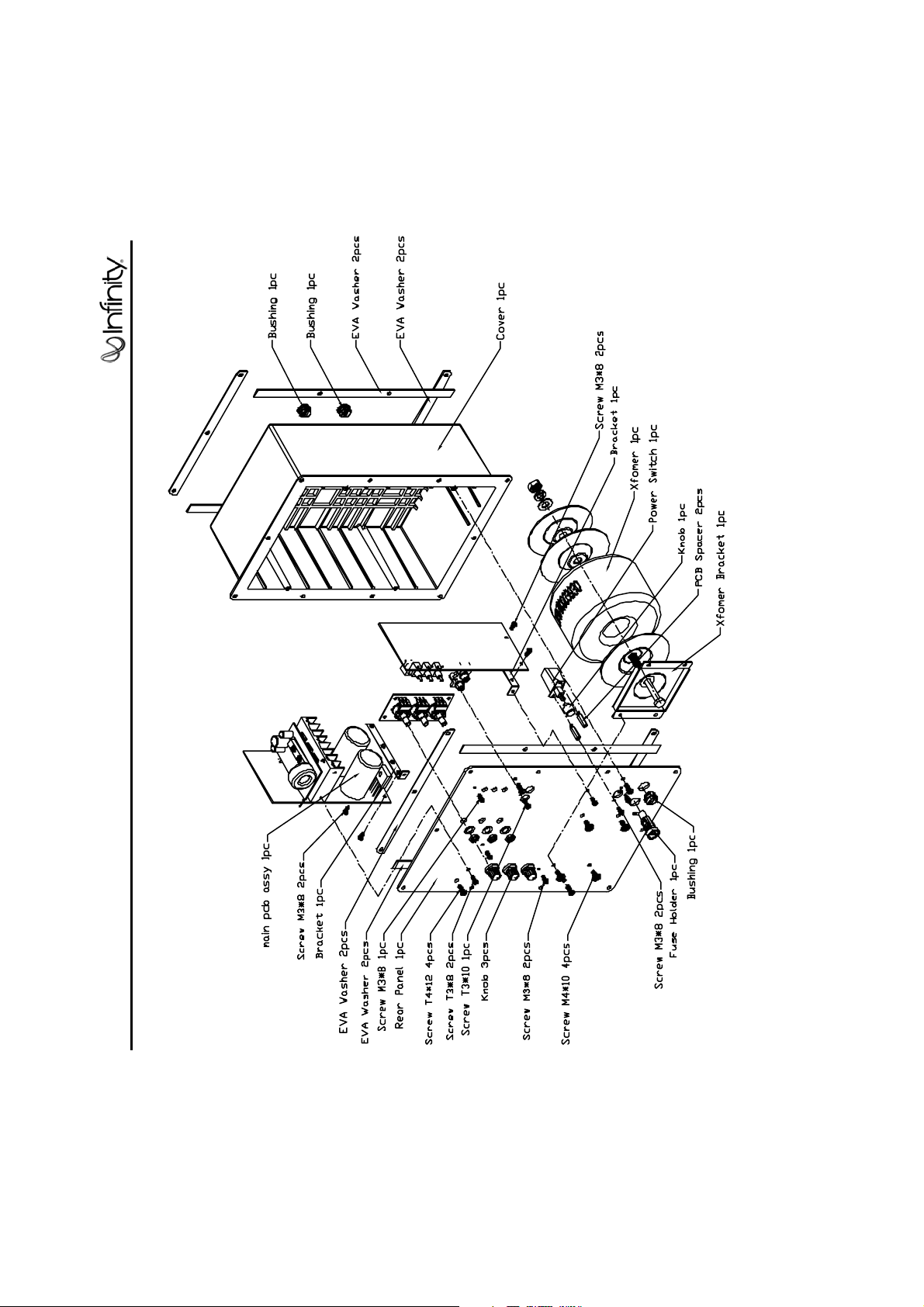
MSW-II
MSW-II Subwoofer
EXPLODED VIEW
14
13
1
2
3
4
3
5
12
11
10
9
8
3
ITEM
NO. DESCRIPTION QTY. PART NO.
1. GRILLE (CHARCOAL) 1 244-120-00268-0YA
(PLATINUM) 244-120-00268G
2. GRILLE CUP (Charcoal) 4 327-RUB-00112B
(Platinum) 327-RUB-00112W
3. WOOFER/AMPLIFIER/BAFFLE 25 352-FM04020D605
SCREWS
4. FRONT BAFFLE (Charcoal) 1 243-120-00399B
(Platinum) 1 243-120-00399W
5. 12" WOOFER C.M.M.D .,SHIELDED, 1 30PR14BW-DW01
DCR = 3.51 ±10%
6. MSW-II SUBWOOFER CABINET 1 Not for Sale
(CHARCOAL OR PLATINUM)
6
7
ITEM
NO. DESCRIPTION QTY. PART NO.
7. AMPLIFIER ASSEMBLY 1 Not for Sale
8. FOOT (Charcoal) 4 320-ABS-00193B
(Platinum) 4 320-ABS-00193W
9. FOOT PAD (Charcoal) 4 320-RUB-00192B
(Platinum) 4 320-RUB-00192W
10. PORT TUBE 1 249-ABS-00158
11. FOOT SCREW 4 352-HM05025D606
12. WIRING HARNESS (AMP-LEVEL POT)1 165-50400HH4
13. LEVEL CONTROL PCB 1 015-AA000-00113
14. LEVEL CONTROL SCREWS 3 352-CM03509D439
MSW-II Subwoofer
8
Page 10
:
MSW-II
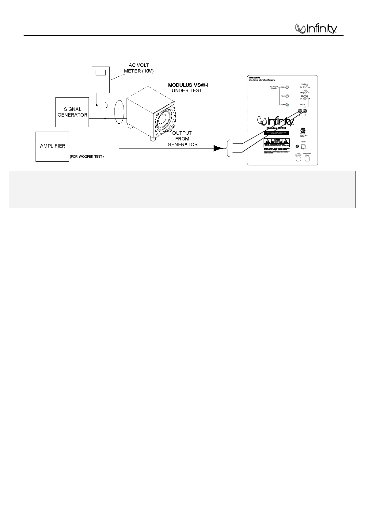
Modulus MSW-II TEST PROCEDURE
The operation of the Modulus MSW-II subwoofer, and the proper settings for the Room Adaptive Bass Optimization System,
or R.A.B.O.S., is thoroughly covered in the Owner’s guide, part# 406-000-00921.
For service purposes, the R.A.B.O.S. system is canceled when all three front panel controls (F) (L) (W) are turned fully CW
(Clockwise), or if the R.A.B.O.S. On/Off switch is OFF. The only other control of concern is the Main Level Control on the
front panel, which operates like a traditional potentiometer.
Equipment needed:
x Function/signal generator/sweep generator
x Integrated Amplifier
x Multimeter
x RCA cables; Speaker cables
General Unit Function (UUT = Unit Under Test)
Switch/Controls:
MAIN LEVEL control full clockwise (0)
LOW PASS FILTER switch OFF
R.A.B.O.S. On/Off switch OFF
PHASE button - either position
(3) R.A.B.O.S. controls – do not matter
1) From the signal generator, connect one line level (RCA) cable to the Input jacks (L/R) on the UUT. Use a Ycable from a mono source if necessary to connect to both inputs.
2) Turn on generator; adjust to 150mV, 50 Hz.
3) Plug AC power cord in UUT, turn power switch ON.
4) Red LED should ON (in the Level wheel at the front of the UUT). Turn up LEVEL control to full
counterclockwise (10).
5) Green LED should ON; Bass response should be heard and felt from port tube opening.
6) Turn LEVEL control full clockwise (0). Turn power switch OFF.
Sweep Function
1) Follow steps 1-3 above, using a sweep generator as a signal source – adjust the generator to 100mV, 50 Hz.
2) Sweep generator from 20Hz to 300Hz. Listen for any rattles, clicks, buzzes or any other noises. If any unusual
noises are heard, test woofer according to the instructions below.
Driver Function
1) Remove woofer from the enclosure; (see exploded view on page 8).
2) Check DC resistance of woofer; it should be 3.5
±10%,
3) Connect a pair of speaker cables to woofer terminals. Cables should be connected to an integrated amplifier
fed by a signal generator. Turn on generator and adjust so that speaker level output is 6.0V.
4) Sweep generator from 20Hz to 1kHz. Listen to driver for any rubbing, buzzing, or other unusual noises.
9
Page 11

MSW-II
Modulus II Electrical Parts List
Part Number Description Qty Reference Designator
MAIN/POWER PCB
Resistors
110-16101j26 Resistor 100ȍ 1/6W ± 5% 26mm 2 R241,244
110-16102j26 Resistor 1K 1/6W ± 5% CF 26mm 3 R210,329,264
110-16103j26 Resistor 10K 1/6W ± 5% CF 26mm 8 R227,229,230,231,232,233,260,261
110-16153j26 Resistor 15K 1/6W ± 5% CF 26mm 2 R247,249
110-16182j26 Resistor 1.8K 1/6W ± 5% CF 26mm 1 R248
110-16222j26 Resistor 2.2K 1/6W ± 5% CF 26mm 2 R242,245
110-16274j26 Resistor 270K 1/6W ± 5% CF 26mm 1 R240
110-16333j26 Resistor 33K 1/6W ± 5% CF 26mm 1 R211
110-16334j26 Resistor 330K 1/6W ± 5% CF 26mm 1 R209
110-16391j26 Resistor 390ȍ1/6W ± 5% CF 26mm 2 R243,246
110-16472j26 Resistor 4.7K 1/6W ± 5% CF 26mm 4 R217,219,222,213
110-16473j26 Resistor 47K 1/6W ± 5% CF 26mm 1 R221
110-16683j26 Resistor 6 8K 1/6W ± 5% CF 26mm 1 R212
116-161002f26 metal film resistor 10K ± 1%MF 1/6W 25mm 4 R160,166,234,235
116-161103f26 metal film resistor 110K ± 1%MF 1/6W 26mm 1 R174
116-161301f26 metal film resistor 1.30K ± 1%MF 1/6W 26mm 3 R226,228,236
116-161502f26 metal film resistor 15.0K ± 1%MF 1/6W 26mm 2 R162,168
116-161822f26 metal film resistor 18.2K ± 1%MF 1/6W 26mm 1 R214
116-162001f26 metal film resistor 2.00K ± 1%MF 1/6W 26mm 1 R215
116-162492f26 metal film resistor 24.9K ± 1%MF 1/6W 26mm 2 R257,258
116-163571f26 metal film resistor 3.57K ± 1%MF 1/6W 26mm 1 R157
116-166813f26 metal film resistor 681K ± 1%MF 1/6W 26mm 1 R262
110-12621j15 Resistor 620ȍ1/2W ± 5% CF 15mm 1 R238
110-20152j20 Resistor 1.5K 2W ± 5% CF 15mm 1 R208
113-500r1j10 cement 0.1ȍ 5W ± 5% 2 R224,225
Capacitors
130-2f104z503 disc capacitor 0.1U 50V +80/-20% 2 C163,164
130-ch101j503 disc capacitor 100P 50V ± 5% 2 C159,160
132-223ja03 mylay capacitor 0.022uF 100V ± 5% 8 C172,173,174,175,176,177,178,179
135-3107m16 electrolytic cap 100uF 16V ± 20% 2 C166,167
135-3226m50 electrolytic cap 22U 50V ± 20% 2 C161,162
135-3227m10 electrolytic cap 220U 10V ± 20% 2 C156,157
139-3227m16
135-4228m35 electrolytic cap 2200uF 35V ± 20% 2 C170,171
135-4688m80 electrolytic cap 6800U 80V ± 20% 2 C168,169
Semiconductors
190-161431clp1 IC TL431CLP 1 D115
192-027c1815gr transistor 2SC1815GR 1 Q110,112,117
192-028a1015gr transistor 2SA1015GR 3 Q111,113,115
192-1672n5551 transistor 2N5551 1 Q109
192-1682n5401 transistor 2N5401 AI-PNP 350V 500mA TO-92 1 Q108
197-031n4148 diode 100mA 75V SIGNAL 1N4148 ROHM 7 D117,118,119,120,121,125,126
199-15000565
199-15001505 zener diode 15V 1/2W 52mm 1 D122
199-15002005 zener diode 20V 1/2W 52mm 1 D129
190-161m324n IC LM324N 1 U107
192-991d669a transistor HI-SINCERITY HSD669A 1 Q116
192-992b649t transistor HSB649T 1 Q118
197-00db103g diode 1A 200V DF02M 1 D124
197-00kbu1003 diode 10A 200V KBU1003 1 D123
197-101n4002 diode 1N4002 1 D114
electrolytic 220uF 16V ± 20%
zener diode 5.6V 1/2W 52mm
1 C155
1 D116
10
Page 12

MSW-II
Part Number Description Qty Reference Designator
Miscellaneous
109-1tsc103j0 thermister TSC05103J 1 R237
162-10149001 wire ass'y 140mm AWG28 1 P107
171-udhss124d relay 5A 24V UDH-SS124D 1 K101
175-1d02v01 wire connector 2PIN PITH=3.96mm 1 P112
175-1d05v01 wire connector 5PIN 3.96mm 1 P113
INPUT PCB
Resistors
110-14152j26 resistor 1.5K 1/4W ± 5% CF 26mm 1 R150
110-16101j26 resistor 100ȍ 1/6W ± 5% CF 26mm 4
110-16102j26 resistor 1K 1/6W ± 5% CF 26mm 1 R140
110-16103j26 resistor 10K 1/6W ± 5% CF 26mm 11 R263,118,126,129,133,136,146,149,191,196,199
110-16105j26
110-16106j26
110-16151j26
110-16154j26
110-16183j26
110-16203j26
110-16221j26
110-16223j26
110-16432j26
110-16472j26
110-16473j26
116-161001f26
116-161002f26
116-161052f26
116-161210f26
116-161301f26
116-161303f26
116-161504f26
116-161693f26
116-162001f26
116-162052f26
116-162211f26
116-162212f26
116-162322f26 metal film resistor 23.2K 1/6W ± 1% MF 26mm 4 R124,125,127,128
116-163162f26
116-163400f26
116-163923f26
116-164021f26
116-164320f26
116-164750f26
116-164751f26
116-164752f26
116-165111f26
116-165623f26
116-166041f26
116-166491f26
116-169311f26
116-201211f20
resistor 1M 1/6W ± 5% CF 26mm
resistor 10M 1/6W ± 5% CF 26mm
resistor 150ȍ 1/6W ± 5% CF 26mm
resistor 150K 1/6W ± 5% CF 26mm
resistor 18K 1/6W ± 5% CF 26mm
resistor 20K 1/6W ± 5% CF 26mm
resistor 220ȍ 1/6W ± 5% CF 26mm
resistor 22K 1/6W ± 5% CF 27mm
resistor 4.3K 1/6W ± 5% CF 27mm
resistor 4.7K 1/6W ± 5% CF 27mm
resistor 47K 1/6W ± 5% CF 27mm
metal film resistor 1K 1/6W ± 1% MF 26mm
metal film resistor 10K 1/6W ± 1% MF 26mm
metal film resistor 10.5K 1/6W ± 1% MF 26mm
metal film resistor 121ȍ 1/6W ± 1% MF 26mm
metal film resistor 1.30K 1/6W ± 1% MF 26mm
metal film resistor 130K 1/6W ± 1% MF 26mm
metal film resistor 1.5M 1/6W ± 1% MF 26mm
metal film resistor 169K 1/6W ± 1% MF 26mm
metal film resistor 2.00K 1/6W ± 1% MF 26mm
metal film resistor 20.5K 1/6W ± 1% MF 26mm
metal film resistor 2.21K 1/6W ± 1% MF 26mm
metal film resistor 22.1K 1/6W ± 1% MF 26mm
metal film resistor 31.6K 1/6W ± 1% MF 26mm
metal film resistor 340ȍ 1/6W ± 1% MF 26mm
metal film resistor 392K 1/6W ± 1% MF 26mm
metal film resistor 4.02K 1/6W ± 1% MF 26mm
metal film resistor 432
metal film resistor 475ȍ 1/6W ± 1% MF 26mm
metal film resistor 4.75K 1/6W ± 1% MF 26mm
metal film resistor 47.5K 1/6W ± 1% MF 26mm
metal film resistor 5.11K 1/6W ± 1% MF 26mm
metal film resistor 562K 1/6W MF 26mm
metal film resistor 6.04K 1/6W ± 1% MF 26mm
metal film resistor 6.49K 1/6W ± 1% MF 26mm
metal film resistor 9.31K 1/6W ± 1% MF 26mm
metal film resistor 1.21K 2W ± 1% MF 20mm
ȍ 1/6W ± 1% MF 26mm
R112,113,151,152
2 R145,181
1 R186
1 R139
1 R138
1 R147
1 R200
2 R119,120
2 R141,148
1 R254
2 R144,250
1 R137
3 R180,187,194
8
R130,131,132,159,171,173,178,192
1 R188
1 R252
1 R253
1 R190
1 R142
1 R195
1 R202
2 R197,198
1 R172
3 R193,204,206
1 R135
1 R164,169
1 R201
1 R134
1 R265
1 R251
5 R108,109,110,205,207
2 R121,122
1 R189
1 R117
2 R165,170
2 R114,115
1 R179
1 R104
Capacitors
129-a104j633
129-a223j633
129-a473j633
129-a474j633
130-2b102k503
130-2b221k503
130-2f104z503 disc capacitor 0.1U 50V +80/-20% 13
130-3f473m503
metallize capacitor 0.1U 63V ± 5% MSC
metallize capacitor 0.022U 63V ± 5% MSC
metallize capacitor 0.047U 63V ± 5% MSC
metallize capacitor 0.47U 63V ± 5% MSC
disc capacitor 1000P 50V ± 10%
disc capacitor 220P 50V ± 10%
disc capacitor 0.047U 50V ± 20%
11
6 C116,137,138,139,143,118
1 C150
4 C117,119,142,149
2 C121,122
3 C165,181,182
4 C105,107,108,128
C112,114,124,125,130,133,135,144,145,146,147,153
,154
1 C180
Page 13

B
MSW-II
Part Number Description Qty Reference Designator
130-sl101k503
130-sl470k503 disc capacitor 47P 50V ± 10% 1 C127
135-3105m50 electrolytic 1U 50V ± 20% 1 C126
135-3106m50
135-3107m16
135-3107m25
135-3226m50
135-3475m50
139-3227m16
Semiconductors
192-027c1815gr transistor 2SC1815GR 3 Q101,102,103
197-131n4148 diode 1N4148 26mm 7 D105,106,108,109,110,112,113
199-15000825 zener diode 8.2V 1/2W 52mm 1 D130
190-06m4558d IC OPA 4558D 2 U101,103
190-161m324n IC LM324N 1 U106
190-16tl1072n IC TL072N @6.5 1 U105
190-16tl1074cn IC TL074CN ST 2 U102,104
192-153mpf102 transistor FAIRCHILD MPF102 1 Q107
Miscellaneous
174-0rcb202vag RCA JACK RCA-209 1 JK102
175-1c02v01 wire connector 2PIN PITCH=2.5mm 2 P106,108
175-1c04v01 wire connector 4PIN PITCH=2.5mm 1 P101
175-1c06v01 wire connector 6PIN PITCH=2.5mm 1 P105
180-t000ts8l switch L101 T2 3 SW102,103,104
disc capacitor 100P 50V SL ± 10%
electrolytic 10uF 50V ± 20%
electrolytic 100uF 16V ± 20%
electrolytic 100U 25V ± 20%
electrolytic 22U 50V ± 20%
electrolytic 4.7U 50V ± 20%
electrolytic 220uF 16V ± 20%
3 C110,120,148
4 C109,111,123,129
5 C113,115,132,134,136
1 C152
1 C151
1 C102
1 C131
RABOS CONTROL PC
110-16474j26
110-164r7j26
116-161000f26
116-162671f26
116-165400f26 metal film resistor 540ȍ 1/6W ± 1% MF 26mm 1 R175
116-166800f26
116-168250f26
115-h103a203 variable resistor RV16A01-20-15K-A10K-3E 2 R158,177
115-h103c201 variable resistor RV16A01-20-15K-C10K-3E 1 R163
162-50150002 wire 150mm AWG26 BLCK 1 P102
162-50150003 wire 150mm AWG26 BLCK 2 P103,104
resistor 470K 1/6W ± 5% CF 27mm
resistor 4.7ȍ 1/6W ± 5% CF 26mm
metal film resistor 100ȍ 1/6W ± 1% MF 26mm
metal film resistor 2.67K 1/6W ± 1% MF 26mm
metal film resistor 680ȍ 1/6W ± 1% MF 26mm
metal film resistor 825ȍ 1/6W ± 1% MF 26mm
1 R143
1 R153
1 R154
1 R155
1 R176
2 R161,167
Power Amp Class D Module part# 051-A00444C01 RECOMMENDED: REPLACE ENTIRE MODULE
Resistors
118-12061001j SMD resistor 1.00K 1206 5% 1 R2
118-12061002j SMD resistor 10.0K 1206 5% 6 R25,29,30,30B,7,9
118-120610r0j SMD resistor 10.0ȍ1206 5% 4 R20,20B,22,23
118-12062002j SMD resistor 20.0K1206 5% 1 R26
118-12062201j SMD resistor 2.20K 1206 5% 19
118-12062204j SMD resistor 2.20M 1206 5% 1 R4
118-12062701j SMD resistor 2.70K 1206 5% 1 R10
118-12063000j SMD resistor 300.0ȍ 1206 5% 1 R24
118-12063301j SMD resistor 3.30K 1206 5% 5 R1,14,15,27,28
118-12063902j SMD resistor 39.0K 1206 5% 1 R3
118-12064700j SMD resistor 470ȍ 1206 5% 3 R8,11,21
118-12064701j SMD resistor 4.70K 1206 5% 2 R5,12
R6,13,16,31,33,34,35,36,37,38,39,40,41,42,43,44,45,
46,32
Capacitors
141-c0101k50 SMD capacitor 100pF 50V 10% 1206 NP0 1 C4
141-c0220k50 SMD capacitor 22pF 50V 10% 1206 SMT NP0 1 C5
141-c0561k50 SMD capacitor 560pF 50V 10% 1206 NP0 1 C6
141-c5104m50 SMD capacitor 1206 Y5V 0.1uF 50V ± 20% 8 C2,3,7,8,9,10,11,15
12
Page 14

MSW-II
Part Number Description Qty Reference Designator
141-c7223k50 SMD capacitor 0.022uF 50V 10% 1206 X7R 1 C13
141-d7104ka0 SMD capacitor 0.1uF 100V 10% 1206 X7R 4 C12,14,18,19
141-d7104ka5 SMD capacitor 0.1uF 250V 10% 1210 X7R 1 C20
132-105kb50 mylar capacitor 1uF 250V ± 10% 1 C40
128-e106ma01-s non-polar 10uF 100V 20% 2 C16,17
Semiconductors
190-16tl072dts SMD I.C TL072CDT SGS THMSON 1 IC1
192-09124126qs SMD transistor 2SC2412K-T146Q/R ROHM 2 Q1,4
192-09139066rs SMD transistor 2SC3906K-T146R ROHM 2 Q2,8
192-091sc4672 SMD transistor 2SC4672(MPT3) ROHM 1 Q5B
192-09210376qs SMD transistor 2SA1037K-T146Q/R ROHM 2 Q7,9
192-09215146rs SMD transistor 2SA1514K-T146R ROHM 1 Q3
197-03rls4148s SMD diode RLS4148-TE11 ROHM 8 D1,2,3,4,5,5B,6,20
199-15000563s SMD zener diode 5.6V 5% PHILIPS BZX84-C5V6 2 Z1,2
199-15001203s SMD zener diode 12V 5% PHILIPS BZX84-C12 4 Z3,4,5,6
192-232irf9640 transistor FET IRE9640 IR P-CH TO220 2 Q10,10B
192-233irf640 transistor FET IRE640 IR N-CH TO-220 1 Q11
192-1682n5401 transistor 2N5401K AI-PNP 350V 500mA TO-92 1 Q6B
Miscellaneous
122-13151k0190 inductor CHOKE SA-500-280 1 L1
122-14300k4 inductor Ferrite core LD1215*300KU ± 10% 1 L2
175-9f40hr2 wire connector 40PIN PITCH=2.54mm HR2*40 0.2
MISC/MECHANICAL
150-r1107005 power transformer
152-u602015 line cord SVT FT-26FT 1
154-k31505t0 Fuse 3.15A 250V 30mm UL/CSA 1
155-63032i Fuse holder HTB-32I 30mm UL/CSA 1
302-AL-05001-1 Alu plate 200*300*2.5t 1
306-ABS-00180 Back cover 1
310-ABS-00107 ABS £r11*14.25 black 1
311-ABS-00028 KNOBS 46077-W soft P.V.C. 3
333-EVA-00783 EVA W 198*12*2.0T 2
333-EVA-00807 EVA L 274*12*2.0T 2
333-EVA-00826 EVA W 198*12*1.0T 2
333-EVA-00835 EVA L 274*12*1.0T 2
335-NYL-00002 strain relief 4K-4 NO-BB 2
350-EM04012D024 4F*12 screw 4
351-AM03008A079 M3*8 screw 5
351-HM04010A217 M4*10 screw 4
352-AM03008D040 F3*8 B type screw 2
352-AM03010D065 F3*10 P type screw 1
361-FE-00002 Transformer holder 90*70*15mm 1
362-CU-05000 M3*16.5H 2
236-AL-05001 Alumium strip 1
323-AL-05000 heat sink 1 1
351-AM03008A078 M3*8 coating nickel 2
351-HM03006A308 screw M3*6mm 1
351-HM03018A307 Screw M3*18mm 2
352-AM03008D041 F3*8 B type screw 2
362-FE-00013 B brckt L TYPE t=1.6mm 89*9*1.6T 2
351-AM03008A078 M3*8 screw 2
165-50701xx01 wire assembly 700mm UL2464 #22 1 P108 1
180-pspaw7az PUSH SWITCH PS3-22SPA-W7AZ 1
193-201612tr Insulator T0-220 16mm*12mm 1
193-201815t2 Insulator 1
193-0s4211 silicon (INSULATION SPACER)42*11 1
333-EVA-00220 EVA pad 225*15*1t UL 1
333-SPG-00849 Sponge 330L*30W*5T 1
335-NYL-00010 Wire holder 5P-4 1
13
Page 15

MSW-II
Part Number Description Qty Reference Designator
162-10140002 UL/CSA 1617 #22 140mm BLACK 1
176-wjce2 Terminal CE-2 1
165-50400HH4 WIRING HARNESS (AMP-LEVEL POT) 1
015-AA000-00113 LEVEL CONTROL PCB 1
352-CM03509D439 LEVEL CONTROL SCREWS 3
14
Page 16

MSW-II
15
Page 17

MSW-II
16
Page 18

MSW-II
17
Page 19

18
MSW-II
Page 20

19
MSW-II
Page 21

20
MSW-II
Page 22

21
MSW-II
Page 23

22
MSW-II
Page 24

23
MSW-II
Page 25

24
MSW-II
Page 26

25
MSW-II
Page 27

26
MSW-II
Page 28

27
MSW-II
Page 29

28
MSW-II
Page 30

MSW-II
29
Page 31

Modulus II
Packaging
406-000-00921 (OWNER’S MANUAL) & 405-000-00328 (WARRANTY CARD)
POSITIONED ON THE TOP OF INNER CARTON
398-FE-00264
(BUBBLE LEVEL AND
METAL PLATE)
INFINITY
431-000-00956 (POLYFOAM SET TOP/BOTTOM)
PLASTIC BAG
431-000-01014 (EPE)
431-000-00956 (POLYFOAM SET TOP/BOTTOM)
431-000-00958 (POLYFOAM SET TOP/BOTTOM)
PLASTIC BAG
431-000-00958 (POLYFOAM SET TOP/BOTTOM)
400-000-04383 (INNER CARTON)
402-000-01845 (GIFT BOX)
373-000-00128
BATTERY
398-ABS-00312
(TESTING DISK)
398-PVC-00263
(PVC SHEET)
221-000-00344 (PVC COVER)
033-000-00101 (ABS MICROPHONE)
431-000-00957 (POLYFOAM SET TOP/BOTTOM)
PLASTIC BAG
431-000-00957 (POLYFOAM SET TOP/BOTTOM)
GIFT BOX 402-000-01774 (PLATINUM)
402-000-01772 (CHARCOAL)
30
 Loading...