

Infinity MOUNTAIN BICYCLE, BMX BICYCLES Owner's Manual

Owner’s Manual
BICYCLE
Copyright © 2014 Infinity Cycle Works Ltd. All rights reserved.
Any Questions or Concerns?
Call Toll Free
phone: 1-855-521-1127
www.infinitycycleworks.com
Assembly
Parts Identification
3
2
1
Before You Ride
Servicing
4
Detailed Mainenance
5

Introduction
i
Congratulations on your new bike!
Infinity Cycleworks is dedicated to making sure you
are satisfied with your new bicycle and want to help
with any questions or comments you may have.
Visit us online at:
www.infinitycycleworks.com
For customer service visit:
www.infinitycycleworks.com
DO NOT return this product to the store.
Please contact Infinity Cycleworks for assistance.
Bicycle Ownerʼs Manual
Proof of Purchase
ii
Bicycle Owner’s Manual
Serial Number
iii
PLEASE RETAIN YOUR SALES RECEIPT
AS PROOF OF PURCHASE
NOTES:
_________________________________________________________________
_________________________________________________________________
_________________________________________________________________
_________________________________________________________________
_________________________________________________________________
_________________________________________________________________
_________________________________________________________________
_________________________________________________________________
####
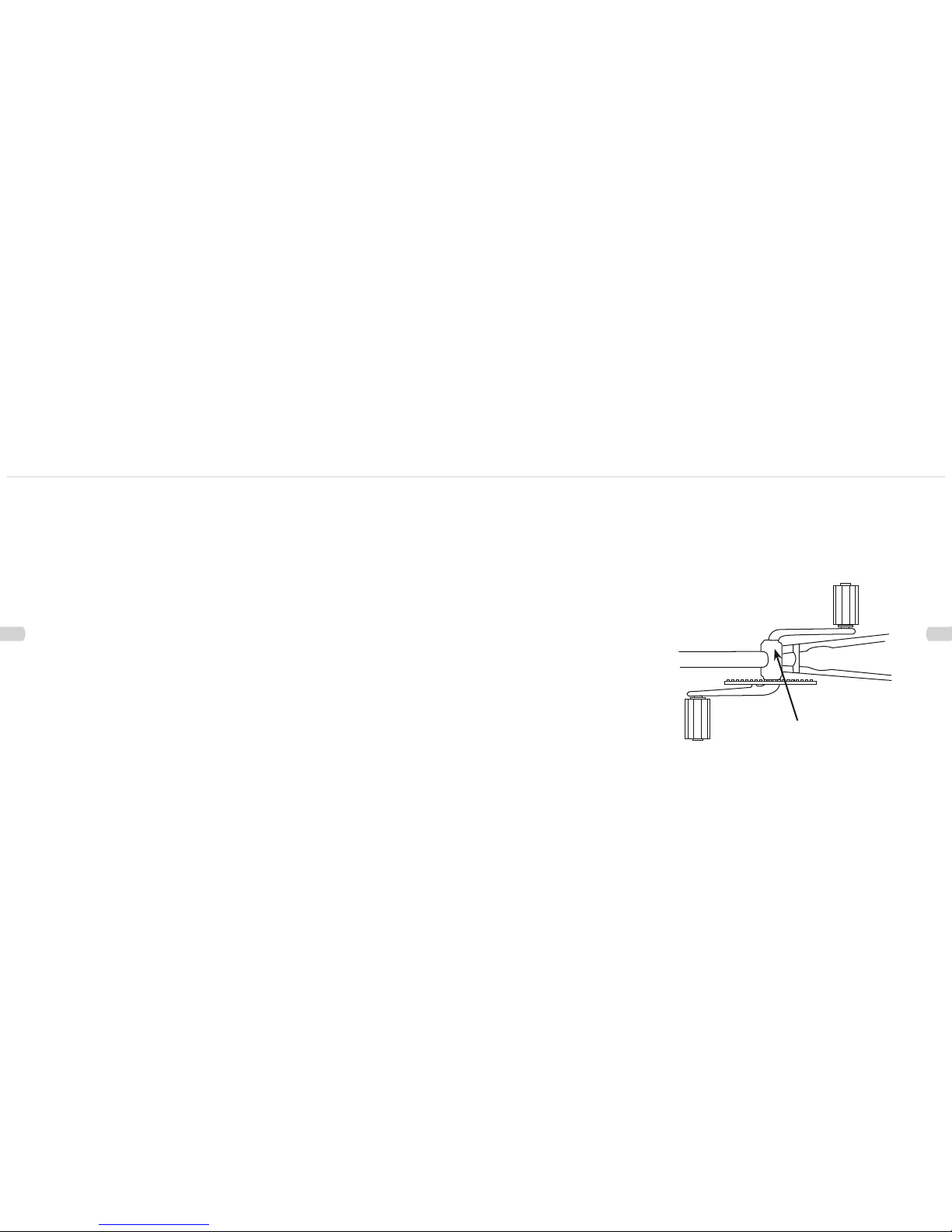
Serial Number Location
Bike Shown Upside Down
Serial Number
The following manual is only a guide to assist you and is not a complete or comprehensive manual of all aspects of maintaining and repairing your
bicycle. The bicycle that you have purchased is a complex object. Infinity Cycleworks recommends that you consult a bicycle specialist if you have
doubts or concerns as to your experience or ability to properly assemble, repair, or maintain your bicycle. You will save time and the
inconvenience of having to go back to the store if you choose to write or call us concerning missing parts, service questions, operating advice, and/
or assembly questions.
Infinity Cycleworks
722 Chester
Road Delta, BC
Canada
Phone: (604) 521-1127
www.infinitycycleworks.com
Constomer Service:
www.infinitycycleworks.com

Directory Directory
Directory
iii
Table of Contents
iv
PART 1
SECTIONS
PARTS IDENTIFICATION . . . . . . . . . . . . . . 6
BEFORE YOU RIDE . . . . . . . . . . . . . . . 10
ASSEMBLY . . . . . . . . . . . . . . . . . . . . 24
SERVICING . . . . . . . . . . . . . . . . . . . . 58
DETAILED MAINTENANCE . . . . . . . . . . . 62
PART 2
PART 3
PART 4
PART 5
PARTS IDENTIFICATION 6
MOUNTAIN BICYCLE 6
BMX BICYCLES 7
TOOLS REQUIRED 8
BEFORE YOU RIDE 10
CORRECT FRAME SIZE 10
RIDING POSITION 11
Saddle Height 11
Reach 11
Handlebar Height 12
SAFETY CHECKLIST 13
1. Brakes 13
2. Wheels and Tires 13
3. Steering 13
4. Chain 13
5. Bearings 14
6. Cranks and Pedals 14
7. Derailleurs 14
8. Frame and Fork 14
9. Accessories 14
Helmets 15
RIDING SAFELY 16
General Rules 16
Wet Weather 17
Night Riding 17
Pedaling Technique 17
Hill Technique 18
Cornering Technique 18
Rules for Children 18
GEARS - HOW TO OPERATE 19
Derailleur Gears 19
Operating Principles 19
Hand Grip Shifters 20
Thumb shifters (Top Mounted) 21
Below the Bar Shifters 21
BICYCLE CARE 22
Basic Maintenance 22
Storage 23
Security 23
ASSEMBLY 24
DERAILLEUR GEARED BICYCLES 24
Getting Started 24
Handlebars 24
Forks 26
Seat and Seat Post 27
Pedals & Cranks Set 28
Front Wheel 29
Correct Quick Release Axle Setting 29
Front Brake 30
Cantilever Brakes – Link Wire 30
Cantilever Brakes – Straddle Cable 32
V-Style Brakes 32
Check your Brakes 35
Disk Brakes 36
DERAILLEUR 38
Rear Derailleur 38
Front Derailleur 39
Dual Suspension 40
Rear Pivots 41
Accessories 42
Reflectors 42
Final Check 43
SINGLE SPEED & BMX 44
Getting Started 44
Handlebars 44
Seat 45
Pedals & Crank Set 45
Front Wheel 46
Front Brake 46
Side Pull Brake 48
Cantilever Brakes – Link Wire 48
Cantilever Brakes – Straddle Cable 52
Check your Brakes 53
Training Wheels 53
Rotors 54
Final Check 56
SERVICING 58
ROUTINE MAINTENANCE 58
Schedule 1 - Lubrication 58
Schedule 2 - Service Checklist 59
Tools Required 60
Travel Tools 60
DETAILED MAINTENANCE 62
WHEELS AND TIRES 62
Wheel Inspection 62
Tire Inspection 63
Recommended Tire Pressures: 63
Hub Bearing Adjustment 64
How To Fix a Flat Tire 64
HANDLEBARS AND STEM 66
Handlebar Stem
66
WARNING 66
Handlebars 67
GRIP SHIFTERS 68
Grip Shift – Installation 68
Cables and Cable Housing 69
HEADSET 70
Inspection
70
Adjustment 70
SUSPENSION FORK 71
Regular Maintenance 71
Reassembly 71
Check before each ride: 71
SADDLE AND SEAT POST 72
Inspection 72
Lubrication 72
Adjustment 73
Brakes 74
Inspection 74
Lubrication 75
Adjustment – Sidepull Calipers 75
Adjustment – Cantilever Calipers 76
DRIVETRAIN 78
Pedals 78
Inspection 78
Attachment 79
Lubrication and Adjustment 79
CRANK SET 80
Inspection 80
Lubrication and Adjustment – One Piece
Cranks 81
Lubrication and Adjustment – Cotterless
Cranks 82
Lubrication 84
Adjustment and Replacement 84
Chain 84
Inspection 84
FREEWHEEL 85
Inspection
85
Lubrication 86
COASTER HUB 86
DERAILLEUR SYSTEMS 87
Inspection 87
Lubrication 88
Adjustment – Rear Derailleur 88
Adjustment – Front Derailleur 89
Mountain Bicycle
1
1
BMX Bicycle
1
1
Parts Identification Parts Identification
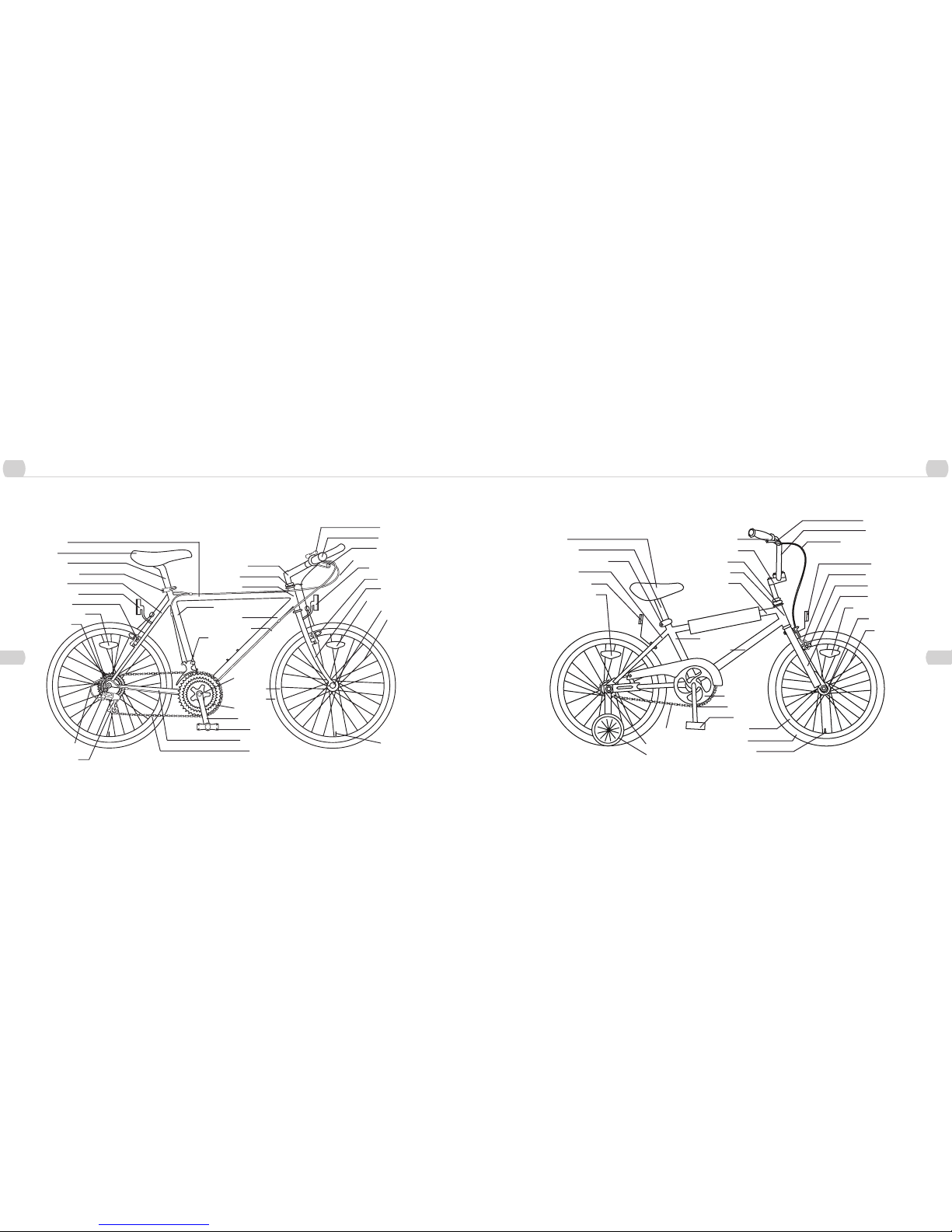
MOUNTAIN BICYCLE
Mountain bicycles are designed to give maximum comfort over a wide variety of road surfaces. The wider handlebars and convenient
shift lever position make them very easy to control. Wider rims and tires give them a softer ride with more traction on rough surfaces.
The frame and fork on mountain style bicycles are much sturdier than those on racing style bicyles.
Top Tube
Seat
Seat Post
Quick Release
Seat Stay
Rear Reflector
Rear Brake
Wheel Reflector
Freewheel
Shift
Lever
Handlebar
Brake
Lever
Brake Control
Cables
Front Reflecto
r
Front
Brake
Front
Fork
Wheel
Reflector
Front Hu
b
Spokes
Handlebar Stem
Head Set
Head Tube
Seat Tube
Down Tube
Gear Control Cable
Front Derailleur
Bottom
Bracket Axle
Rim
Tire
Chain Wheel
Crank Arm
Pedal
Chainstay
Chain
Tire V
alve
Rear Derailleur
Gear Control
Cable
6
7
BMX BICYCLES
BMX style bicycles are a popular genereal purpose type most suited for young riders. They are valued because of their sturdy and
simple construction, and low mainenance.
Seat
Seat Post
Seat Post Binder Bolt
Seat Stay
Rear Reflector
Wheel Reflector
Chain Wheel
Crank Arm
Pedal
Rim
Tire
Tire Valve
Chain
Rear Sprocket
Training Wheels
Brake Lever
Handlebar
Brake Control Cable
Reflector
Front Brake
Brake Pad
Front Fork
Wheel Reflector
Front Hub
Spokes
Handlebar Grip
Handlebar Stem
Head Set
Head Tube
Top Tube
Seat Tube
Down Tube
8
Tools Required
1
1
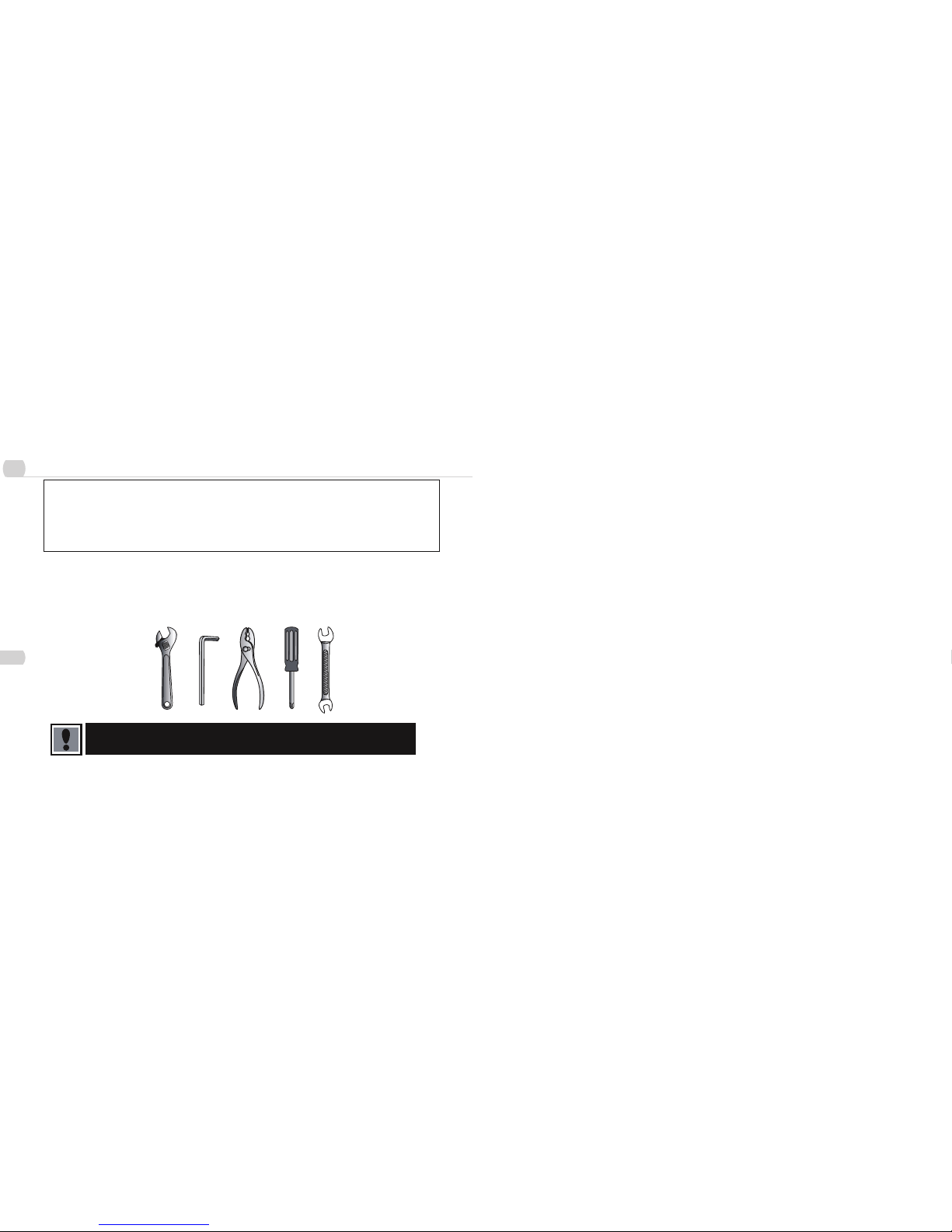
TOOLS REQUIRED
Your new bicycle was assembled and tuned in the factory and then partially disassembled for shipping. You may
have purchased the bicycle already fully reassembled form. The following instructions will enable you to prepare
your bicycle for years of enjoyable cycling. For more details on inspection, lubrication, maintenance and adjustment
of any are, please refer to the relevant sections in this manual. If you need replacement parts or have any
questions pertaining to assembly of your bicycle, call Infinity Cycleworks Bicycles direct at:
Infinity Cycleworks BICYCLES SERVICE AND TECHNICAL SUPPORT:
1-855-521-1127
Monday – Friday 9:00 am – 5:00 pm Pacific Time
To avoid injury, this product must be properly assembled before use. If your bicycle was obtained assembled, we
strongly recommend that you review the complete assembly instructions, and perform checks specified in this
manual before riding.
2 2
Before You Ride Before You Ride
Correct Frame Size
2
10
Riding Position
2
11
CORRECT FRAME SIZE
When selecting a new bicycle, the correct choice of frame size is a very important safety conideration. Most full sized bicycles come in
a range of frame sizes. These sizes usually refer to the distance between the center of the bottom bracket and the top of the frame seat
tube.
For safe and comfortable riding there should be a clearance of between 25mm and 50mm between the groin area of
the intended rider and the top tube of the bicycle frame, while the rider straddles the bicycle with both feet flat on
the ground.
The ideal clearance will vary between types of bicycles and rider preference. This makes straddling the frame when off the saddle easier
and safer in situations such as sudden traffic stops. Women can use a men’s style bicycle to determine the correct size the women’s
model.
The following chart and diagram will help you make the correct choice.
Approximate Rider Leg
Lenth
Suggested Frame Size for
Racing/Touring Bicyle
Suggested Frame Size for
Mountain or Hybrid Bicycle
24 – 27 inches / 61 – 69cm – 14.5 inches / 37cm
26 – 30 inches / 66 – 76cm – 17 inches / 43cm
28 – 31 inches / 71 – 79cm 19.5 inches / 50cm 18 inches / 45cm
30 – 33 inches / 76 – 84cm 21.5 inches / 55cm 19.5 inches / 50cm
31 – 34 inches / 79 – 86cm 22.5 inches / 57cm 20.5 inches / 52cm
32 – 35 inches / 81 – 89cm 23.5 inches / 60cm 21–22 inches / 53 – 56cm
34 – 37 inches / 86 – 94cm 25 inches / 63 cm 23 – 23.5 inches / 58 – 60cm
not less than 1 inch
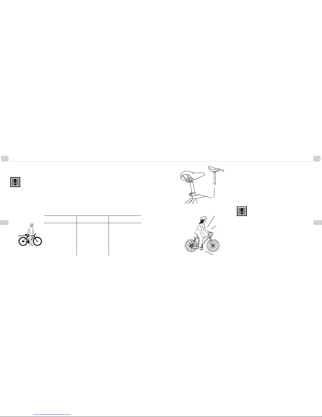
RIDING POSITION
Saddle Height
In order to obtain the most comfortable riding position and offer the best
possible pedaling efficiency, the seat height should be set correctly in
relation to the rider’s leg length. The correct saddle height should not allow
leg strain from over extension, and the hips should not rock from side
to side while pedaling. While sitting on the bicycle with one pedal at its
lowest point, place the ball of your foot on that pedal. The correct saddle
height will allow the knee to be slightly bent in this position. If the rider then
places the heel of that foot on the pedal, the leg should be almost straight.
Ensure that the seat pillar does not extend beyond the
minimum insertion mark.
(Refer to p.65 on how to adjust seat height.)
Reach
To obtain maximum comfort, the rider should not overextend his or her
reach when riding.
To adjust this distance, the position of the seat can be altered in relation to
the seat pillar. (Refer to p.65 on how to adjust the seat clamp.)
Maximum Height / Mini-
mum Insertion Mark
(Should not be visible)
Arms not over-
extended
Handlebar stem
height about the
same as
seat height
Pedal at
bottom position
2 2
Before You Ride Before You Ride
Handlebar Height
2
12
Safety Check List
2
13
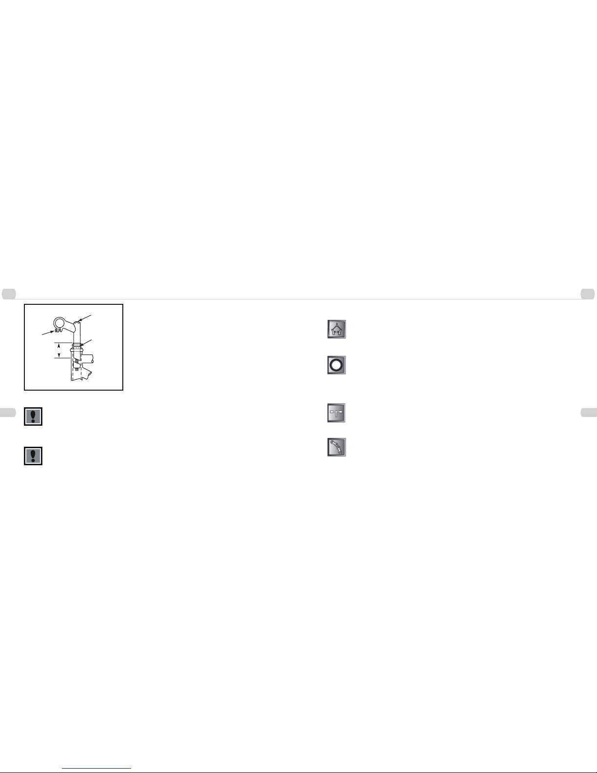
Handlebar Height
Maximum comfort is usually obtained when the handlebar height is equal to
the height of the seat. You may wish to try different heights to find the most
comfortable position.
Ensure that the handlebar stem does not extend beyond the minimum
insertion mark. Failure to do this may cause serious bodily injury
or damage to the bicycle. Ensure both the Stem Wedge Bolt and the
Handlebar Binder Bolt are tightened securely. Failure to do this may cause
loss of steering control. (Refer to p. 59 on how to adjust handlebars).
Warning: Overtightening the stem bolt or headset assembly may cause
damage to the bicycle and/or injury to the rider.
Stem Wedge Bolt
Maximum Height/
Minimum Insertion
Mark
Handlebar Binder Bolt
Exceeds 2 1/2
(64mm)
SAFETY CHECKLIST
Before every ride, it is important to carry out the following safety checks:
1. Brakes
– Ensure front and rear brakes work properly.
– Ensure brake shoe pads are not over worn and are correctly positioned in relation to the rims.
– Ensure brake control cables are lubricated, correctly adjusted, and display no obvious wear.
– Ensure brake control levers are lubricated and tightly secured so the handlebar.
2. Wheels and Tires
– Ensure tires are inflated to within the maximum recommended limit as displayed on the tire side wall.
– Ensure tires have tread and have no bulges or excessive wear.
– Ensure rims run true and have noobvious wobbles or kinks.
– Ensure all wheel spokes are tight and not broken.
– Check that axle nuts are tight. If your bicycle is fitted with quick release axles, make sure locking levers are correctly
tensioned and in the closed position.
3. Steering
– Ensure handlebar and stem are correctly adjusted and tightened, and allow proper steering.
– Ensure that the handlebars are set correctly in relation to the forks and the direction of travel.
– Check that the head set locking mechanism is properly adjusted and tightened.
– If the bicycle is fitted with handlebar end extensions, ensure they are properly positioned and tightened.
4. Chain
– Ensure chain is oiled, clean and runs smoothly.
– Extra care is required in wet or dusty conditions.
2 2
Before You Ride Before You Ride
Safety Check List
2
14
Helmets
2
15
5. Bearings
– Ensure all bearings are lubricated, run freely and display no excess movement, grinding or rattling.
– Check headset, wheel bearings, pedal bearings and bottom bracket bearings.
6. Cranks and Pedals
– Ensure pedals are securely tightened to the cranks.
– Ensure cranks are securely tightened to the axle and are not bent.
7. Derailleurs
– Check that front and rear mechanisms are adjusted and function properly.
– Ensure control levers are securely attached.
– Ensure derailleurs, shift levers and control cables are properly lubricated.
8. Frame and Fork
– Check that the frame and fork are not bent or broken.
– If either are bent or broken, they should be replaced.
9. Accessories
– Ensure that all reflectors are properly fitted and not obscured.
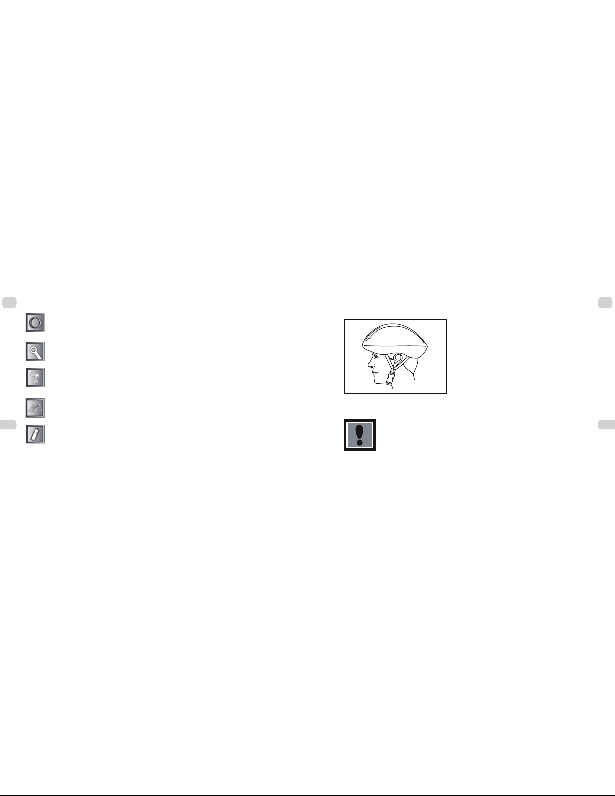
Helmets
It is strongly advised that a properly fitting, ANSI or SNELL approved,
bicycle safety helmet be worn at all times when riding your bicycle. In
addition, if you are carrying a passenger in a child safety seat, they must
also be wearing a helmet.
The correct helmet should:
- be comfortable
- be lightweight
- have good ventilation
- fit correctly
Always wear a properly fitted helmet when riding a bicycle.
2 2
Before You Ride Before You Ride
Riding Safely
2
16
Riding Safely
2
17
RIDING SAFELY
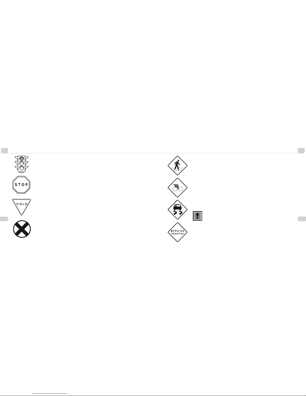
General Rules
When riding obey the same road laws as all other road vehicles, including giving way to pedestrians, and
stopping at red lights and stop signs.
For further information, contact the Road Traffic Authority in your State.
Ride predictably and in a straight line. Never ride against traffic.
Use correct hand signals to indicate turning or stopping.
Ride defensively. To other road users, you may be hard to see.
Concentrate on the path ahead. Avoid pot holes, gravel, wet road markings, oil curbs, speed bumps, drain
grates and other obstacles.
Cross train tracks at a 90 degree angle or walk your bicycle across.
Expect the unexpected such as opening car doors or cars backing out of concealed driveways.
Be extra careful at intersections and when preparing to pass other vehicles.
Familiarize yourself with all the bicylce’s features. Practice gear shifts, braking, and the use of toe clips and
straps, if fitted.
If you are wearing loose pants, use leg clips or elastic bands to prevent them from being caught in the chain.
Don’t carry packages or passengers that will interfere with your visibility or control of the bicycle. Don’t use
items that may restrict your hearing.
When braking, always apply the rear brake first, then the front. The front brake is more powerful and if it is not
correctly applied, you may lose control and fall.
Maintain a comfortable stopping distance from all other riders, vehicles and objects.
Safe braking distances and forces are subject to the prevailing weather conditions.
Wet Weather
– In wet weather you need to take extra care.
– Brake earlier, you will take a longer distance to stop.
– Decrease your riding speed, avoid sudden braking, and take corners with additional caution.
– Be more visible on the road.
– Wear reflective clothing and use safety lights.
– Pot holes and slippery surfaces such as line markings and train tracks all become more hazardous when
wet.
Do not ride at night, unless it is absolutely neccessary.
Night Riding
– Ensure bicycle is equipped with a full set of correctly positioned and clean reflectors.
– Refer to p. 84 of this manual.
– Use a properly functioning lighting set comprising a white front lamp and a red rear lamp.
– If using battery powered lights, make sure batteries are well charged.
– Some rear lights available have a flashing mechanism which enhances visibility.
– Wear reflective and light colored clothing.
– Ride at night only if necessary. Slow down and use familiar roads with street lighting, If possible.
Pedaling Technique
– Position the ball of your foot on the center of the pedal.
– When pedaling, ensure your knees are parallel to the bicycle frame.
– To absorb shock, keep your elbows slightly bent.
– Learn to operate the gears properly. (Refer to p. 13-15)
2 2
Before You Ride Before You Ride
Hill Technique
2
18
Gears - How To Operate
2
19
Hill Technique
– Gear down before a climb and continue gearing down as required to maintain pedaling speed.
– If you reach the lowest gear and are struggling, stand up on your pedals. You will then obtain more power from each pedal
revolution.
– On the descent, use the high gears to avoid rapid pedaling.
– Do not exceed a comfortable speed, maintain control and take additional care.
Cornering Technique
Brake slightly before cornering and prepare to lean your body into the corner. Maintain the inside pedal at the 12 o’clock position and
slightly point the inside knee in the direction you are turning. Keep the other leg straight, don’t pedal through fast or tight corners.
Rules for Children
To avoid accidents, teach children good riding skills with an emphasis on safety from an early age.
1. Always wear a properly fitted helmet.
2. Do not play in driveways or the road.
3. Do not ride on busy streets.
4. Do not ride at night.
5. Obey all the traffic laws, especially stop signs and red lights.
6. Be aware of other road vehicles behind and nearby.
7. Before entering a street: Stop, look right, left, and right again for traffic. IF there’s no traffic, proceed into the roadway.
8. If riding downhill, be extra careful. Slow down using the brakes and maintain control of the steering.
9. Never take your hands off the handlebars, or your feet off the pedals when riding downhill.
The Consumer Protection Safety Commission advises that the riding of small wheel diameter bicycles at excessive
speeds can lead to instability and is not recommended.
Children should be made aware of all possible riding hazards and correct riding behavior before they take to the streets
- Do not leave it up to trial and error
GEARS - HOW TO OPERATE
Derailleur Gears
Most multy-speed bicycles today are equipped with what are known as
derailleur gears. They operate using a system of levers and mechanisms
to move the drive chain between different sized driving gears or cogs.
The purpose of gears is to let you maintain a constant, steady pedaling
pace under varying conditions. This means your riding will be less tiring
without unnecessary straining up hills or fast pedaling downhill. Bicycles
come with a variety of gear configurations from 5 to 24 speeds. A 5-6
speed bicycle will have a single front chainwheel, a rear derailleur, and 5
or 6 cogs on the rear hub. Bicycles with more gears will also have a front
derailleur, a front chainwheel with 2-3 cogs, and up to 8 cogs on the rear
hub.
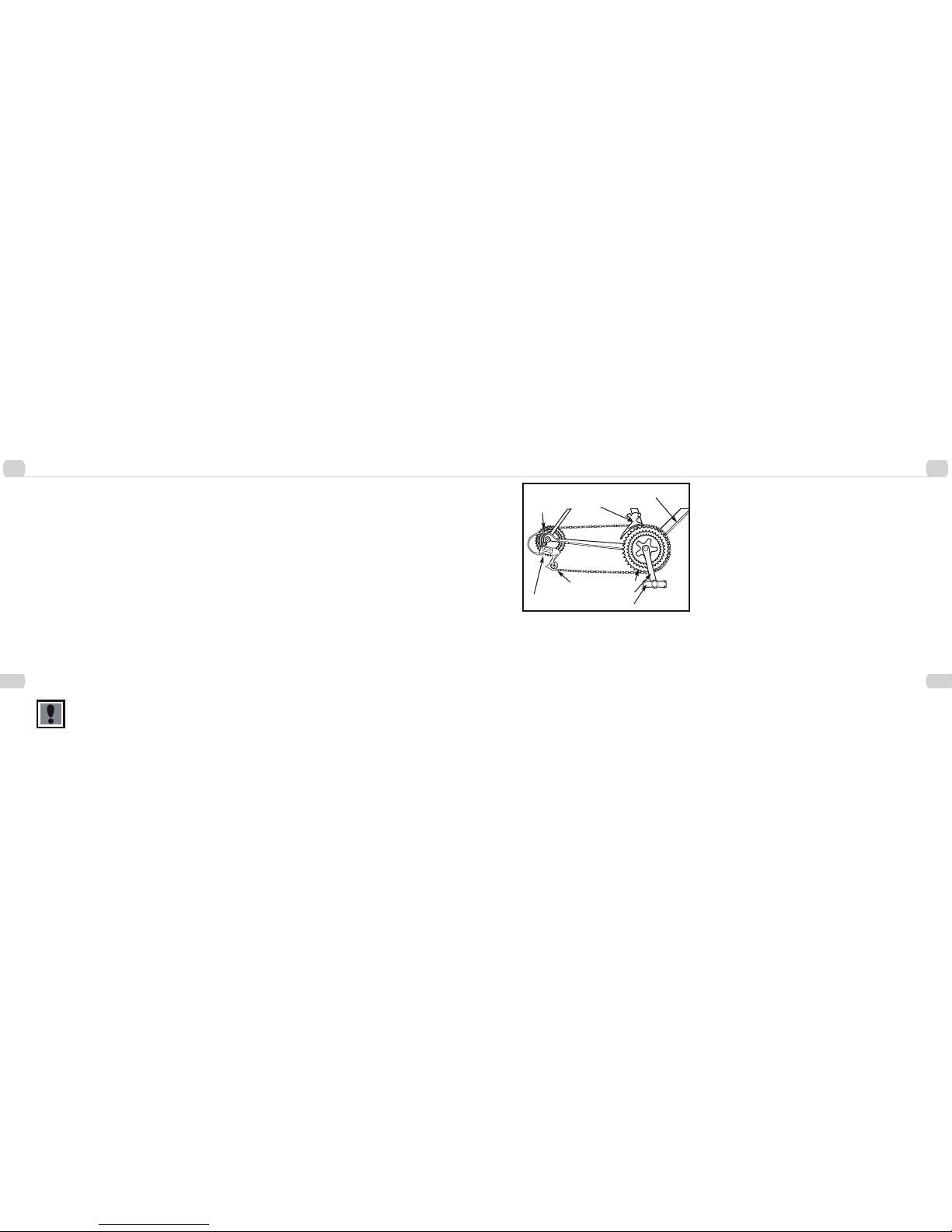
Operating Principles
No matter how many gears, the operating principles are the same. The
front deraileur is operated by the left shift lever and the rear derailleur
by the right. To operate you must be pedaling forward. You can not shift
derailleur gears when you are stopped or when pedaling backwards.
Before shifting ease up on your pedalinhg pressure. On approaching
a hill, shift to a lower gear before your pedaling speed slows down too
much for a smooth shift. When coming to a stop, shift to a lower gear
first so it will be easier when you start riding again. If, after selecting a
new gear position, you hear a slight rubbing noise from the front or rear
gears, gently adjust the appropriate shifter until the noise goes away. For
optimal performance and extended chain life, it is recommended that you
avoid using the extreme combinations of gear positions (diagram p. 14) for
extended periods.
Front Derailleur
Guide Pulley
Rear Derailleur
Front Chainwheels
Crank Arm
Pedal
Derailleur Control
Cable
Freewheel
Cogs

2
2
Before You Ride Before You Ride
Hand Grip Shifters
2
20
Thumb Shifters
2
21
Recommended Chainwheel/Rear Sprocket Gear Combinations
Hand Grip Shifters
Some bicycles are now being equipped with a shifting mechanism called
Grip Shift, which is built into the handlebar grips and does not make use of
separate levers. The actuating mechanism is built into the inside part of the
grip that the web of the thumb and index finger closes around. To select a
lower gear, twist the right shifter toward you to engage a larger rear cog. You
can shift one gear at a time by moving the Grip Shift one click, or through
multiple gears by continued twisting. By twisting the left shifter forward or
away from you, a smaller chainwheel can be selected. To select a higher
gear, twist the right shifter forward or away from you to engage a smaller
rear cog. To engage a larger front chainwheel, twist the left shifter towards
you. Single shifts can be achieved by twisting one click at a time and
multiple shifts by larger twists.
6
5
4
3
2
1
6
5
4
3
2
1
3
2
1
High
Middle Low
2
High1Low
For optimal performance,
NOT RECOMMENDED
For optimal performance,
NOT RECOMMENDED
Front Low Gear Rear Low Gear
Front High Gear Rear High Gear
Thumb shifters (Top Mounted)
Most mountain style bicycles are equipped with shifters mounted on the
top of the handlebars and operated by the thumbs. To select a lower,
easier gear, shift to a bigger rear cog and a small chainwheel. Pull the left
shifter back to operate the derailleur. To select a higher, harder gear, shift
to a smaller rear cog and a larger chainwheel. Push the left shifter forward
fro the front, and pull the right lever back for the rear.
Below the Bar Shifters
Many mountain style bicycles now use a shift lever arrangement mounted
on the underside of the handlebars, which use two levers operated by the
thumb and index finger. To select a lower gear push the larger (lower)
right shifter with your thumb to engage a larger rear cog. One firm push
shifts the chain one cog, continuing to push will move the chain over
multiple cogs. Pulling the smaller (upper) left shifter with your index finger
moves the chain from a larger to a smaller chainwheel. To select a higher
gear pull the smaller (upper) right lever with your index finger to engage a
smaller rear cog. Pushing the larger (lower) left lever with your thumb will
move the chain from a smaller to a larger chainwheel.
Left hand lever Right hand lever
Left hand lever Right hand lever
Top Gear
(Harder)
Small rear sprocket
Large chainwheel
Left hand lever forward
Right hand lever back
Bottom Gear
(Easier)
Large rear sprocket
Small chainwheel
Left hand lever back
Right hand lever forward

2
2
Before You Ride Before You Ride
Bicycle Care
2
22
Storage
2
23
BICYCLE CARE
Basic Maintenance
The following procedures will help you maintain your bicycle for years of enjoyable riding.
For painted frame, dust the surface and remove any loose dirt with a dry cloth. To clean, wipe with a damp cloth soaked in a mild
detergent mixture. Dry with a cloth and polish with car or furniture wax. Use soap and water to clean plastic parts and rubber tires.
Chrome plated bikes should be wiped over with a rust preventative fluid.
Store your bicycle under shelter. Avoid leaving it in the rain or exposed to corrosive materials. Riding on the beach or in coastal areas
exposes your bicycle to salt, which is very corrosive. Wash your bicycle frequently and wipe or spray all the unpainted part with an
anti-rust treatment. Make sure wheel rims are dry so braking performance is not affected. After rain, dry your bicycle and apply anti-rust
treatment.
If the hub and bottom bracket bearings of your bicycle have been submerged in water, they should be taken out and re-greased. This
will prevent accelerated bearing deterioration.
If paint has become scratched or chipped to the metal, use touch up paint to prevent rust. Clear nail polish can also be used as a
preventative measure.
Regularly clean and lubricate all moving parts, tighten components and make adjustments as required. (Refer to Parts 4 and 5 of this
manual for further details).
The use of alloy components and BED, SATIN, and TITANIUM surface treatments minimizes the number of places where rust can
surface.
Storage
Keep your bicycle in a dry location away from the weather and the sun.
Ultraviolet rays may cause paint to fade or rubber and plastic parts to
crack.
Before storing your bicycle for a long period of time, clean and lubricate
all components and wax the frame. Deflate the tires to half pressure and
hang the bicycle off the ground. Don’t store near electric motors as ozone
emissions may affect the rubber and paint. Don’t cover with plastic, as
“sweating” will result, which may cause rusting.
Security
It is advisable that the following steps be taken to prepare for and help
prevent possible theft.
1. Maintain a record of the bicycle’s serial number, generally located on
the frame underneath the bottom bracket.
2. Register the bicycle with the local police.
3. Invest in a high quality bicycle lock that will resist hacksaws and
bolt cutters. Always lock your bicycle to an immovable object if it is left
unattended.
3
3
Assembly Assembly
Derailleur Geared Bicycles
3
24
Derailleur Geared Bicycles
3
25
DERAILLEUR GEARED BICYCLES
Includes 20”, 24”, 26”, 27.5, 29" Wheel Mountain
Bikes Assembly is the same for men and women’s
bikes.
Getting Started
Open the carton from the top and remove the bicycle. Remove the straps
and protective wrapping from the bicycle. Inspect the bicycle and all
accessories and parts for possible shortages. It is recommended that the
threads and all moving parts in the parts package be lubricated prior to
installation. Do not discard packing materials until assembly is complete
to insure that no required parts are accidentally discarded. Assemble your
bicycle following the steps that pertain to your model. NOTE: Your bicycle
may be equipped with different style components than the ones illustrated.
Handlebars
Remove the protective cap from the handlebar stem wedge and loosen
the Allen key bolt using the 6mm Allen key. Some models may use a
13mm hexagonal bolt instead of an Allen key bolt. Place the handlebar
stem into the top of the head tube, ensuring that all cables are free of
tangles. Tighten the stem bolt observing the minimum insertion mark and
checking that the forks and the handlebars are facing forward. Check the
headset for smooth rotation and the top nut is secured tightly. Loosen the
6mm Binder Bolt and rotate the handlebar. Retighten the Binder Bolt to
ensure the handlebar does not rotate in the stem. NOTE: Some bicycles
may be equipped with a stem that has an adjustable angle. In addition
to the normal assembly, these stems will require angling the stem to the
desired position, and securely tightening the 6mm angle bolt located in
the front of the stem bolt. Failure to do this may cause loss of steering
control.
Warning: Over-tightening the stem bolt or the headset
assembly may cause damage to the bicycle and/or injury
to the rider.
Minimum Insertion
Mark
Stem Wedge Bolt
Head Tube
Handlebar Binder Bolt
Top Nut
Wedge
The stem must be inserted so that the minimum insertion
mark cannot be seen.
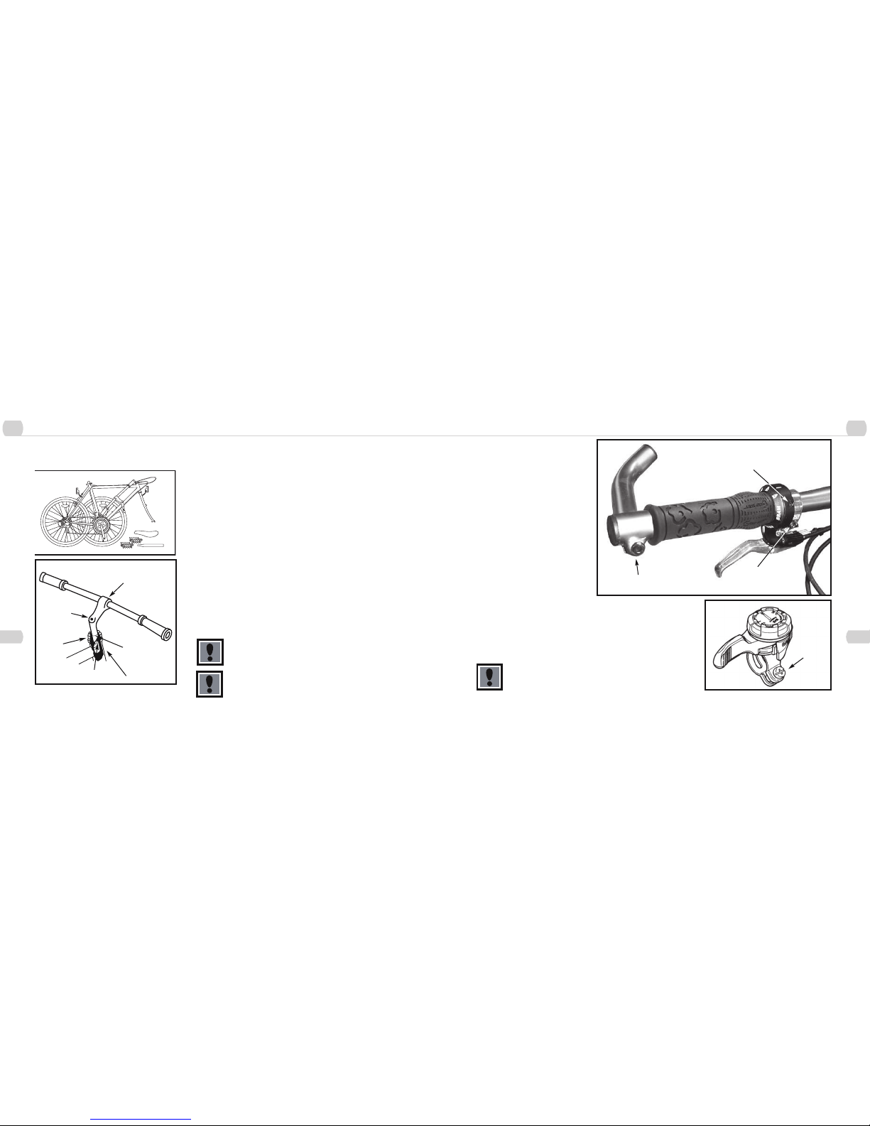
Tighten all bolts that clamp the shifters, brakes levers, and bar end to the handlebar
using a 5mm Allen key or Philips head screwdriver.
(Figure 1) Handlebar with Grip Shifter.
(Figure 2) Top mounted thumb shifter.
Failure to properly tighten clamping bolts may cause sudden
movement of the component resulting in loss of steering control.
1.
Bar end (5mm Allen key)
Shifter binder bolt
(2.5 Allen key)
Brake lever binder bolt
(5mm Allen key)
2.
Shift binder
bolt (Phillips
head or 5mm
Allen key)
33
Assembly Assembly
Forks
3
26
Seat and Seat Post
3
27
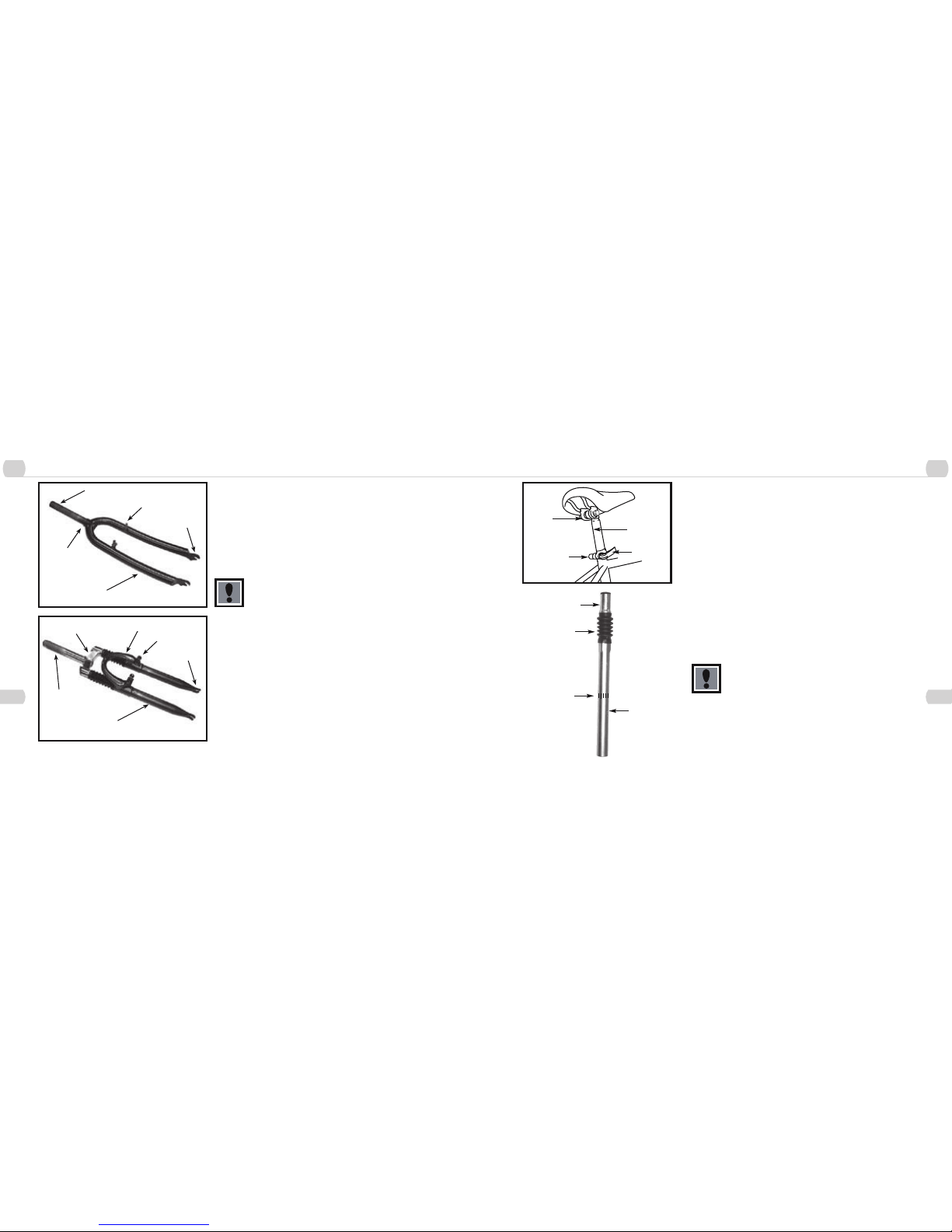
Forks
There are two different types of forks that range in styles and dimensions.
One type is a rigid fork (Figure 1) consisting of stationary tubing with
curved blades. The other type is a suspension fork (Figure 2) consisting
of stanchion tubes riding on elastomers or springs inside of a straight fork
leg. This mechanism acts as a shock absorber with a specified amount
of travel that varies between models. Some suspension forks are not
adjustable and are very difficult to disassemble. If service is needed on a
suspension fork, consult a professional bicycle repair technician.
Do not attempt to disassemble a suspension fork yourself.
Consult a professional bicycle repair technician.
Check the tightness of the headset and the fork. Rotate the fork checking
for smoothness. If it feels like the fork is binding, then an adjustment will
need to be made to the headset. Move the fork in a push/pull manner
checking for tightness. If any play is detected, loosen the top nut,
adjust the bearing cup, and retighten the top nut. Recheck the rotation
and tightness. If necessary, readjust until a smooth rotation is achieved
without backward or forward movement. If your bike is equipped with a
suspension fork, check that the fork compresses and rebounds smoothly.
To do this, place the fork dropouts against the ground, push and release
the handlebar. The fork will generally compress 1-2” and rebound quickly.
Most elastomer type forks will gradually soften with use.
Steering Tube
Crown
Brake Boss
Blade
Drop-out
1.
Steering Tube
Brake Boss
Fork Blade
Drop-out
Brake Bridge
Crown
2.
Seat and Seat Post
Attach the seat to the seat post by inserting the smaller end of the seat post
into the seat clamp and tighten. Insert the larger end of the seat post into
the seat tube of the bicycle frame observing the minimum insertion mark on
the seat post. Turn the adjusting nut of the Quick Release seat bolt to ensure
the locking lever is moved to the closed position with a firm action. Turn the
bicycle upside down and rest in on the seat and handlebars.
NOTE: Comfort bicycles may be equipped with a suspension seat post (See
Diagram-bottom left). Some suspension posts can be adjusted for stiffness
using the preload adjusting screw. Turning the 6mm Allen screw Clockwise
will decrease travel and make the suspension stiffer, while turning the
6mm Allen screw Counter-clockwise will increase travel and make the
suspension less rigid.
Note: In addition to normal assembly, please be aware that the preload
adjusting screw must be flush with the bottom of the post.
Failure to do this may cause irreparable damage.
The seat post must be inserted so that the minimum
insertion mark cannot be seen. The quick release
mechanism must be tightened securely to prevent a sudden
shift of the seat when riding Failure to do this may cause
loss of bicycle control.
Seat
Clamp
Seat
Post
Quick
Release
Adjusting
Nut
Attach
Seat Here
Boot
Minimum
Insertion
Mark
Insert this
end into
frame
3 3
Assembly Assembly
Forks
3
28
Seat and Seat Post
3
29
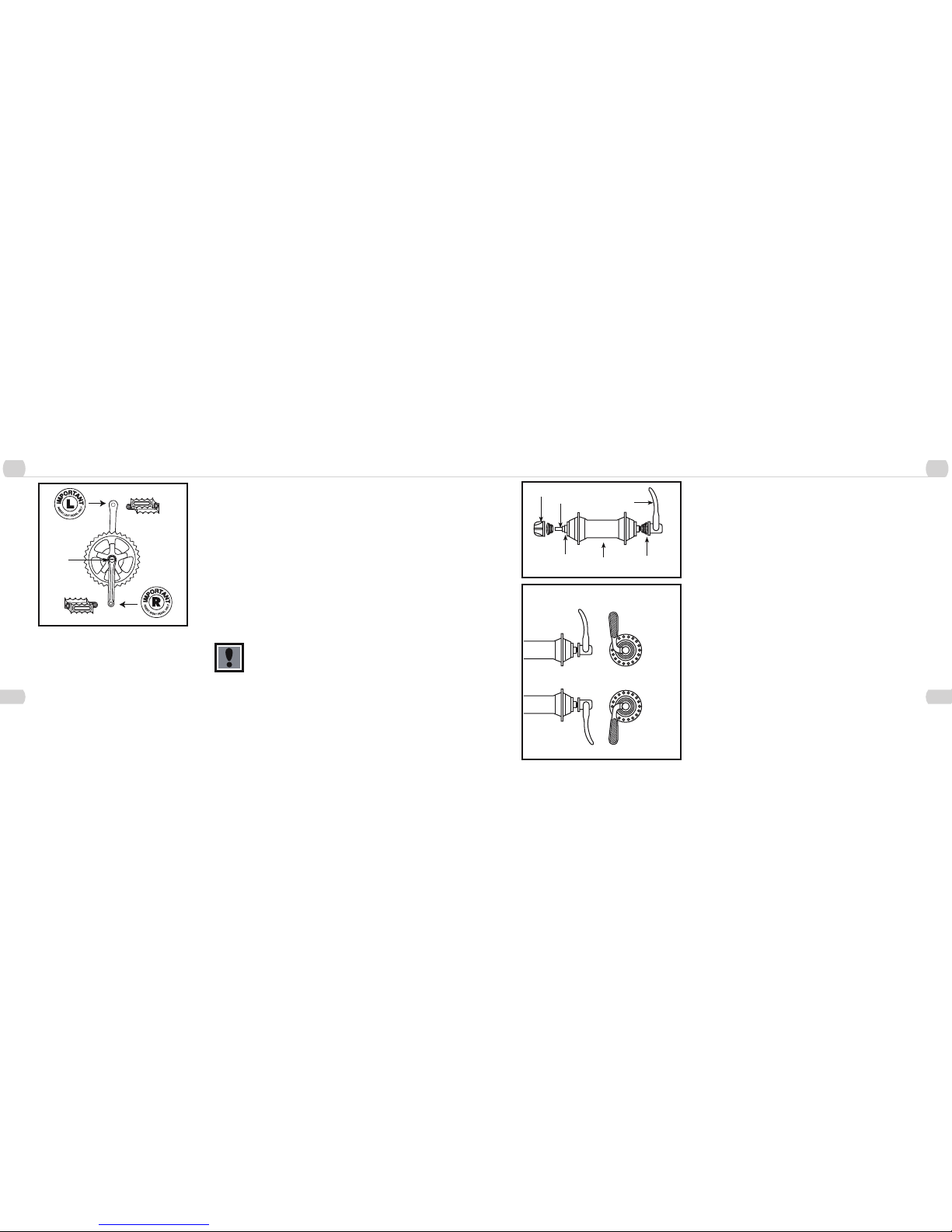
Pedals & Cranks Set
Look for the letters “R” for right, and “L” for left, stamped on each pedal
spindle. Start each pedal spindle by hand to avoid stripping the threads.
Tighten with a 15mm narrow open-ended wrench. Note that the right
hand pedal attaches to the chainwheel side crank arm with a right-hand
(clockwise) thread. The left pedal attaches to the other crank arm and
has a left-hand (counter-clockwise) thread. It is very important that you
check the crank set for correct adjustment and tightness before riding your
bicycle. New cranks may become loose with initial use; refer to p. 74-77
for proper crank set adjustment and maintenance. Once the pedals have
been installed, remove the dust caps from the center of each crank arm.
Using a 14mm socket wrench, tighten the spindle nuts securely (approx.
350 in. lbs) and replace the dust caps.
Attachment of an incorrect pedal into a crank arm will
cause irreplaceable damage.
Dust
Cap
Front Wheel
Check the wheel hub before attaching in to the fork by rotating the threaded
axle. It should be smooth with no lateral movement. Insert the front wheel
into the fork dropouts. Tighten the wheel nuts using the appropriate 14mm
or 15mm wrench. Spin the wheel nuts using the appropriate 14mm or 15mm
wrench. Spin the wheel checking for trueness. Some bicycles have wheel
axles turn the adjusting nut so the locking lever is moved to the closed
position with a firm action. At the halfway closed position of the quick release
lever, you should start to feel some resistance to this motion. Do not tighten
the quick release lever is moved to the closed position with no resistance,
clamping strength is insufficient. Move the quick release lever to the open
position, tighten the quick release adjusting nut, and return the quick release
lever to the closed position.
Correct Quick Release Axle Setting
1. To set, turn the lever to the open position so that the curved part faces
away from the bicycle.
2. While holding the lever in one hand, tighten the adjusting nut until it
stops.
3. Pivot the lever towards the closed position. When the lever is halfway
closed, there must be firm resistance to turn it beyond that point. If
resistance is not firm, open the lever and tighten the adjusting nut in a
clockwise direction.
4. Continue to pivot the lever all the way to the closed position so that the
curved part of the lever faces the bicycle.
Hub
Hub
Axle
Quick Release
Axle
Adjusting
Nut
Quick
Release
Lever
Spring
Closed Position
Open Position
 Loading...