

Page 1

Owner’s Guide
MODULUS®TV BRACKET
®
®
®
Page 2
Before proceeding with assembly,
verify the following contents:
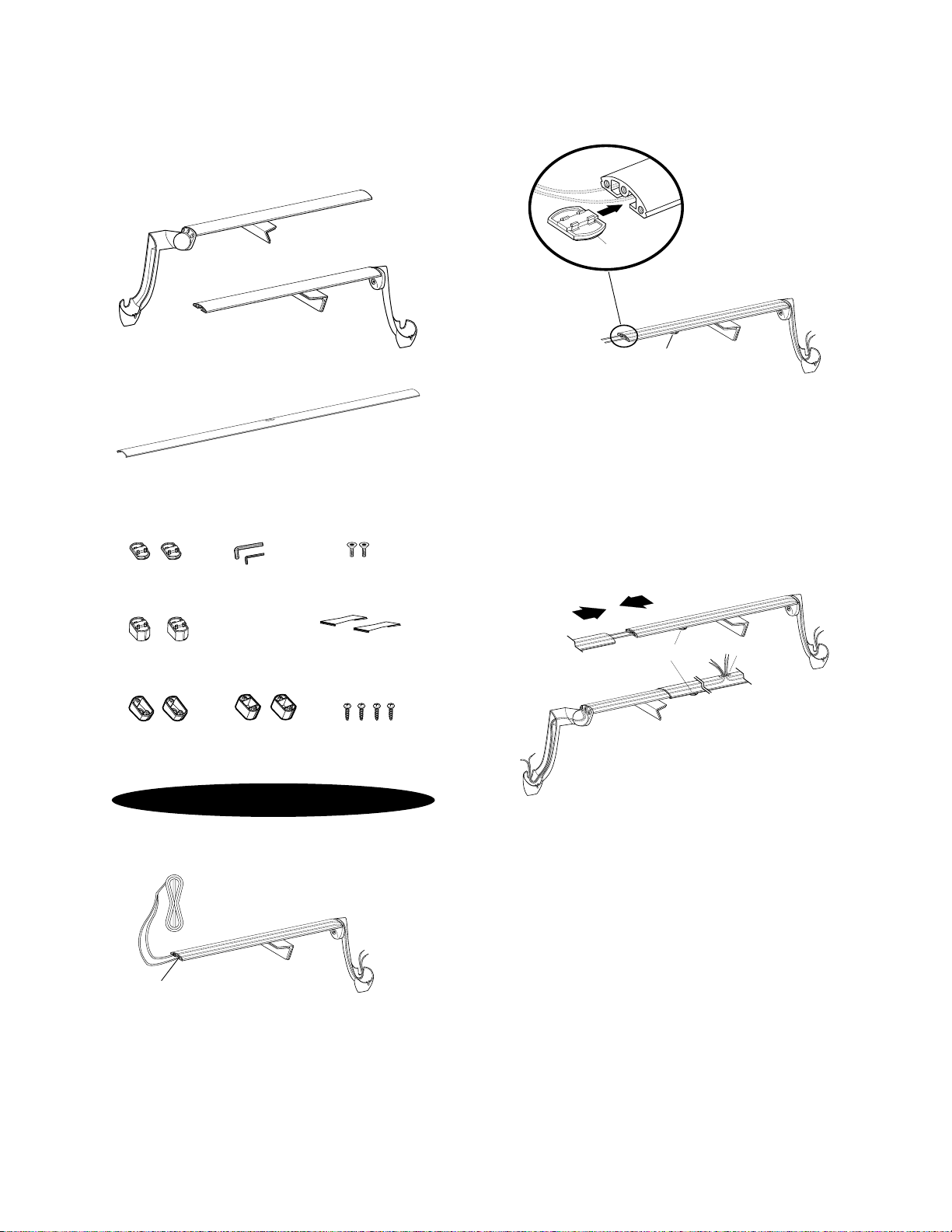
Left and Right Speaker Arms
Center Strut
(2) Flat Support (2) Allen (2) Speaker-
Pads Wrenches Mount Screws
Step One
If you wish to conceal the Speaker Wires,run the wires through
each Arm Assembly before proceeding (remember to leave
enough wire to run through the center strut).The underside of
each speaker arm has two wiring tunnels that provide passage
of the wire through the entire assembly.Do not cut wires
until installation of bracket is complete.Use maximum of
16-gauge wire.
Step Two
Slide one Support Pad into the open end of the Right-Side
Speaker Arm,as shown in the drawing.Repeat for the Left-Side
Speaker Arm.These Support Pads help distribute the weight of
the Modulus TV Bracket across the top of your television.
NOTE:There are two types of Support Pads. Use only the type that
provides the best support of the bracket for the contour of your
television.See Step 5.
Step Three
Slide the Left- and Right-Side-Arm Assemblies into the ends of
the Center Strut with the Speaker-Wire Access Hole toward the
rear.The Modulus TV Bracket is designed to hide the Speaker
Wires by running them through the Center Strut and out the
Speaker-Wire Access Hole.To help support the wire,attach the
two Wire-Guide Tabs to the Center Strut by clipping them into
place. Run the open end of the excess Speaker Wire from each
Arm Assembly out through the Speaker-Wire Access Hole.
SUPPORT
PAD
SPEAKER-WIRE
ACCESS HOLE
LEFT ARM
(FRONT VIEW)
CENTER STRUT
RIGHT ARM
SUPPORT
PAD
SUPPORT
PAD
RIGHT SPEAKER
ARM SHOWN
OPEN END OF
SPEAKER ARM
INSERT HERE
SPEAKER WIRE
RIGHT
SPEAKER ARM
INSTALLING THE BRACKET
(2) Angle Support (2) Wire-Guide Tabs
Pads
(2) Angle Spacers (2) Flat (4) Spacer
Spacers Screws
Page 3
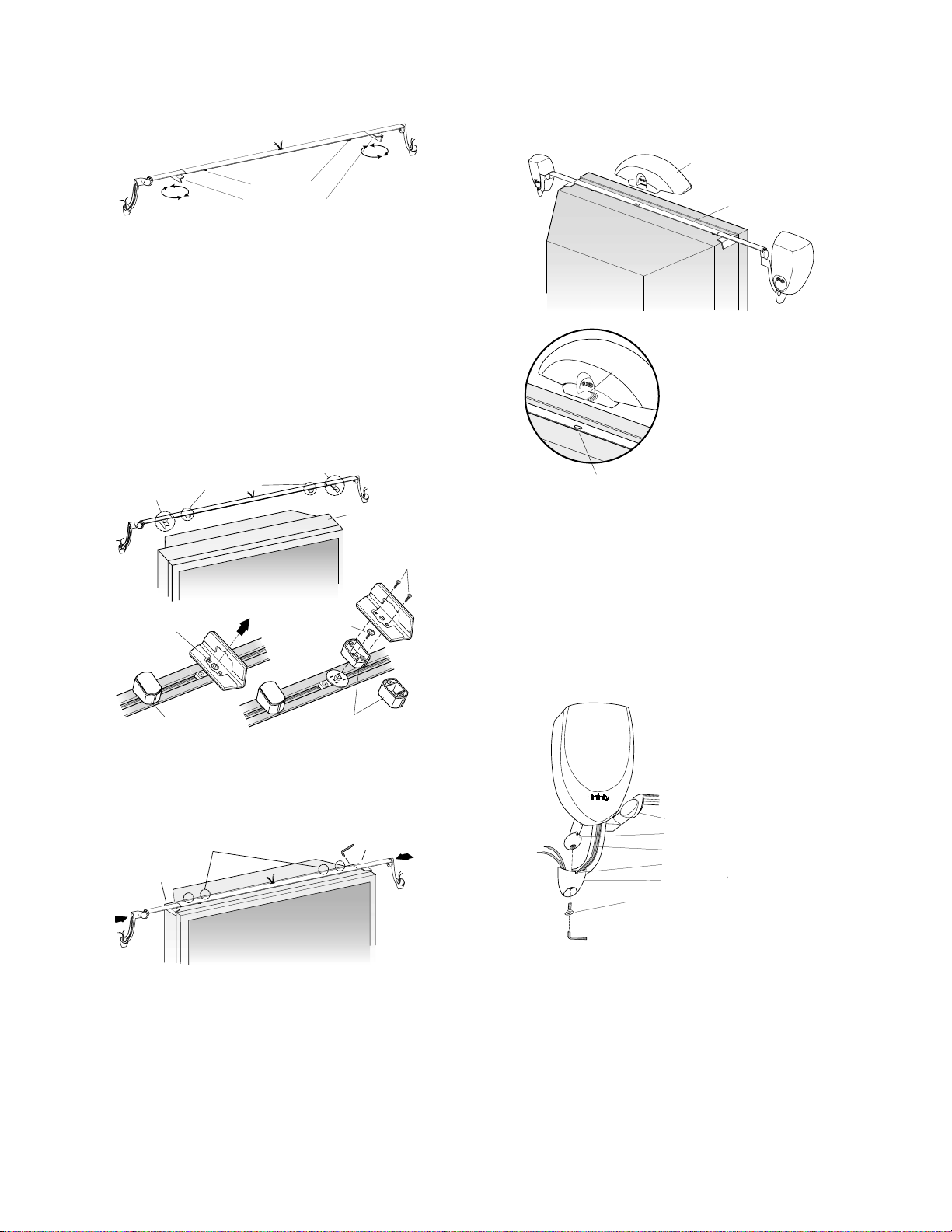
The Modulus TV Bracket has padded L-Shaped Clamps (2) that
hold it to the television.These pivot to allow a secure and snug fit
to the sides of the TV on which it is being mounted. Position them
accordingly. Also position the Support Pads to help distribute the
weight across the top of the TV.
Step Five (if necessary)
In those instances where the top of the TV slopes down, it may be
necessary to attach the provided Angle Spacers or Flat Spacers
to the L-Shaped Support Clamps.
Step Six
Due to the Modulus TV Bracket’s length, two people should be
used to mount it on the TV. Have one person press the two ends
toward each other so that the L-Shaped Clamps snugly hold the
sides of the TV between them. Have the other person use the
smaller Allen Wrench to tighten the four Securing Pins on the
rear of the Center Strut.
NOTE:The Modulus TV Bracket requires a minimum television
width of 30" and a maximum width of 57".
Step Seven
To add stability to the Modulus TV Bracket, attach the CenterChannel Speaker before attaching the Left and Right Side
Speakers.Place the Center Speaker over the Speaker-Wire
Access Hole. Lower the Center Speaker onto the Center Strut and
clip it into place.The Center Speaker will clip onto the assembly
by capturing the rear first;by rocking the Speaker forward, it will
clip onto the front.Now attach the Center’s Speaker Wires.
Step Eight
Remove base from Satellite by unscrewing the Adjustment Screw.
See the Owner’s Guide for your Modulus Speakers for more
details. Set a Satellite into one of the Speaker Arms and align it
so that the Registration Flange fits into the Registration Notch.
Using the larger Allen Wrench, fasten the Speaker-Mount Screw
into the bottom of the Satellite’s mounting ball and tighten.
Repeat Step Seven for other Satellite.
¤
SPEAKER-MOUNT SCREW
SPEAKER ARM
REGISTRATION FLANGE
MOUNTING BALL
REGISTRATION NOTCH
SPEAKER ARM S CUP
SPEAKER-WIRE
ACCESS HOLE
(REAR)
BACK
OPENING
CENTERCHANNEL
SPEAKER
CENTER
STRUT
(4) SECURING PINS
SNUG HOLD
SNUG HOLD
ALLEN
WRENCH
REPLACE THE FLAT PADS
WITH ANGLED PADS
ADD SPACERS
(SEE BELOW)
ADD SPACERS
(SEE BELOW)
SLOPED MOUNTING
SURFACE ON TOP
OF TV
Remove the screw holding
the L-Shaped Support
Secure the Spacer
with the same screw
that was removed
Use either the Angle Spacer
(as shown) or the Flat Spacer,
as needed
Use (2) Spacer
Screws to secure the
L-Shaped Support
to the Spacer
Replace the Flat Pads
with Angle Pads
(if necessary)
L-SHAPED CLAMPS
SUPPORT PADS
NOTE:The Side Speakers are
shown attached. Make sure you
attach the Center-Channel
Speaker
before attaching the
Side Speakers.
Step Four
Page 4

© 2001 Infinity Systems,Inc.,250 Crossways Park Drive,Woodbury, NY 11797 USA (800) 553-3332 (USA Only) www.infinitysystems.com
Infinity is a registered trademark of Infinity Systems, Inc. Printed in USA 04/01 Part No.MODBKTOM
 Loading...