

Infinity Modulus II Infinity, Modulus II Series Owner's Manual

MODULUS®II
H
OME THEATER SYSTEM
Owner’s Guide
230V
ENGLISH
ii
MODULUS II HOME THEATER SYSTEM
Robin Marshall
Harman Consumer Group International
Chateau-du-Loir, France 05/04
Declaration of Conformity
We, Harman Consumer Group Inter national
2, route de Tours
72500 Chateau-du-Loir
France
declare in own responsibility that the products described in
this owner’s manual are in compliance with technical
standards:
EN 61000-6-3:2001
EN 61000-6-1:2001
Declaration of Conformity
We, Harman Consumer Group Inter national
2, route de Tours
72500 Chateau-du-Loir
France
declare in own responsibility that the product described in
this owner’s manual is in compliance with technical
standards:
EN 55013:2001
EN 55020:2002
EN 61000-3-2:2000
EN 61000-3-3:1995+A1:2001
EN 60065:2002
Robin Marshall
Harman Consumer Group International
Chateau-du-Loir, France 05/04
CAUTION
RISK OF ELECTRIC SHOCK
DO NOT OPEN
CAUTION: To prevent electric shock,
do not remove the grounding plug
on the power cord, or use any plug
or extension cord that does not have
a grounding plug provided.
Make certain that the
AC outlet is properly grounded.
Do not use an adapter plug
with this product.
The lightning flash with arrowhead symbol
within an equilateral triangle is intended to
alert the user to the presence of
uninsulated “dangerous voltage” within the
product’s enclosure that may be of
sufficient magnitude to constitute a risk of
electric shock to persons.
The exclamation point within an
equilateral triangle is intended to alert the
user to the presence of important
operating and maintenance (servicing)
instructions in the literature accompanying
the appliance.
read first!
Important Safety Precautions!
1. Read Instructions. All the safety and operating
instructions should be read before the product is
operated.
2. Retain Instructions. The safety and operating
instructions should be retained for future
reference.
3. Heed Warnings. All warnings on the product and
in the operating instructions should be adhered to.
4. Follow Instructions. All operating and use
instructions should be followed.
5.Water and Moisture. The product should not be
used near water – for example, near a bathtub,
washbowl, kitchen sink, laundry tub, in a wet
basement, or near a swimming pool, and the like.
6.Accessories. Do not place this product on an
unstable cart, stand,tripod, bracket, or table.The
product may fall, causing serious injury to a child
or adult, and serious damage to the product. Use
only with a cart, stand,tripod, bracket, or table
recommended by the manufacturer, or sold with the
product.Any mounting of the product should follow
the manufacturer’s instructions, and should use a
mounting accessory recommended by the
manufacturer.
7.Wall or Ceiling Mounting. The product should be
mounted on a wall or ceiling only when and as
recommended by the manufacturer.
8.Ventilation. Slots and openings in the cabinet
are provided for ventilation and to ensure reliable
operation of the product and to protect it from
overheating, and these openings must not be
blocked or covered.
The openings should never be blocked by placing
the product on a bed, sofa, rug,or other similar
surface.This product should not be placed in a
built-in installation such as a bookcase or rack
unless proper ventilation is provided or the
manufacturer’s instructions have been adhered to.
9. Heat. The product should be situated away from
heat sources such as radiators, heat registers,
stoves, or other products that produce heat. If
placed near an
amplifier, check with the
manufacturer for applicability.
10. Power Sources. This product should be
operated only from the type of power source
indicated on the marking label. If you are not sure
of the type of power supply to your home, consult
your product dealer or local power company.For
products intended to operate from battery power,
or other sources, refer to the operating
instructions.
11. Grounding or Polarization. This product
may be
equipped with a polarized alternating
-current line
plug (a plug having one blade wider than the
other).This plug will fit into the power outlet only
one way.This is a safety feature. If you are unable
to insert the plug fully into the outlet, try reversing
the plug. If the plug should still fail to fit, contact
your electrician to replace your obsolete outlet. Do
not defeat the safety purpose of the polarized plug.
12. Power-Cord Protection. Power-supply cords
should be routed so that they are not likely to be
walked on or pinched by items placed upon or
against them, paying particular attention to cords
at plugs, convenience receptacles, and the point
where they exit from the product.
13. Cleaning. Unplug this product from the wall
outlet before cleaning. Do not use liquid cleaners
or aerosol cleaners. Use a damp cloth for
cleaning.
14. Nonuse Periods. The power cord of the product
should be unplugged from the outlet when left
unused for long periods of time.
15. Lightning. For added protection for this
product during a lightning storm, or when it is left
unattended and unused for long periods of time,
unplug it from the wall outlet and disconnect the
antenna or cable system.This will prevent damage
to the product due to lightning and power-line
surges.
16. Overloading. Do not overload wall outlets,
extension cords, or integral convenience
receptacles, as this can result in a risk of fire or
electric shock.
17. Object and Liquid Entry. Never push objects of
any kind into this product through openings,as
they may touch dangerous voltage points or short-
out parts that could result in a fire or electric
shock. Never spill liquid of any kind on the
product.
18. Damage Requiring Service. Unplug this product
from the wall outlet and refer servicing to
qualified service personnel under the following
conditions:
a. The power-supply cord or the plug has been
damaged; or
b. Objects have fallen,or liquid has been spilled
into, the product; or
c. The product has been exposed to rain or water;
or
d. The product does not operate normally when
following the operating instructions.Adjust only
those controls that are covered by the operating
instructions, as an improper adjustment of other
controls may result in damage and will often
require extensive work by a qualified technician
to restore the product to its normal operation;
or
e. The product has been dropped,or the enclosure
damaged; or
f. The product does not appear to operate
normally or exhibits a marked change in
performance.
19.Attachments. Do not use attachments not
recommended by the product manufacturer, as they
may cause hazards.
20. Replacement Parts. When replacement parts
are required,be sure the service technician has
used replacement parts specified by the
manufacturer or that have the same
characteristics as the original part. Unauthorized
substitutions may result in fire, electric shock or
other hazards.
21. Safety Check. Upon completion of any service
or repairs to this product,ask the service
technician to perform safety checks to determine
that the product is in proper operating condition.
22. Servicing. Do not attempt to service this
product yourself, as opening or removing covers
may expose you to dangerous voltage or other
hazards. Refer all servicing to qualified service
personnel.

iii
MODULUS II HOME THEATER SYSTEM
Table of Contents
ii Important Safety Precautions
iv Introduction
iv Technology
iv Ceramic Metal Matrix Diaphragms(CMMD
™
)
iv Room-Friendly Acoustical Design
1 Unpacking the System
2 Planning Your System
2 Placement
5 Center and Satellite Speaker Connections
6 Subwoofer Controls
7 Subwoofer Connections
8 Operation
9 Room Adaptive Bass Optimization System
™
(R.A.B.O.S.™)
10 Contents of the R.A.B.O.S.Test CD
10 R.A.B.O.S.Sound-Level Meter (RSLM)
15 What You Measure, What To Do
18 Adjusting the R.A.B.O.S.Equalizer
19 Final System Balance
19 Maintenance and Service
20 Specifications
21 R.A.B.O.S. Measurement Templates
MODULUS®II HOME T
HEATER
SYSTEM OWNER’S GUIDE
ENGLISH

I
NTRODUCTION
The Infinity Modulus II Home Theater System is a compact,
efficient, universal satellite, center channel and subwoofer system
that is ideal for reproducing multichannel audio and home
theater sound. With their versatile design, the satellite speakers
can be placed virtually anywhere on shelves or stands, or
mounted on a wall using the supplied base.The center channel
can easily be placed on top of, or on a shelf below, the television.
The powered subwoofer delivers tremendous bass performance
from a compact, easy-to-place design.
About This Manual
To start enjoying your new Modulus II Home Theater System, read
and then follow all instructions listed in this guide, as well as
those found in the owner’s manuals of associated components in
your audio system. Save all instructions for future reference.
T
ECHNOLOGY
Modulus loudspeakers incorporate several innovative
technologies that, when implemented by our exceptionally
talented engineers after hours upon hours of subjective listening
evaluations, result in a loudspeaker that realistically and
accurately reproduces the signal source with minimal distortion
and coloration.
Ceramic Metal Matrix Diaphragms™(C.M.M.D.)
For decades, loudspeaker engineers have known that the ideal
transducer should be stiff,yet light, and have high internal
damping (damping is a material’s ability to absorb energy).
Infinity’s C.M.M.D. transducer is a significant advance in
transducer technology.Ceramic, a class of material new to
loudspeakers, offers better performance than other materials.
Ceramic is stiffer than metals and lighter than plastics and
typical composite materials; it also offers improved damping.
These ceramic-based transducers take us a giant step closer to
the ever-elusive “ideal transducer.”
In tweeters, C.M.M.D. technology offers stiffness and damping
superior to that of traditional metals and soft-dome materials.
In woofer and midrange applications, it offers accurate pistonic
operation over the entire frequency range of the driver,
completely eliminating coloration due to cone breakup and
dramatically reducing distortion.And when ceramic-metal-matrix
transducers are exposed to moisture, sunlight or extreme
temperatures, their performance does not deteriorate.
In addition to ceramic diaphragms,the transducers in Modulus
satellite and center channel speakers incorporate full magnetic
shielding to allow use in close proximity to tv receivers and video
monitors.
Room-Friendly Acoustical Design
Driver quality is not the only requirement for exceptional
performance. Infinity’s engineers understand that the room
in which the loudspeaker is placed can greatly affect its
performance.To ensure that Modulus II loudspeakers will sound
exceptional in even the most unexceptional listening environment,
Infinity has developed the proprietary Room Adaptive Bass
Optimization System
™
(R.A.B.O.S.™). With a single band of
parametric equalization, the Modulus II subwoofer can be
adjusted to tame any problematic room-bass resonances
below 80Hz.
We hope you enjoyed this brief introduction to the technology
featured in the Modulus II Home Theater System. If you would like
to further explore Modulus II’s technology and design,please ask
your Infinity dealer for the CMMD and R.A.B.O.S. White Papers.
The White Papers can also be downloaded from Infinity’s Web site
at www.infinitysystems.com.
iv
MODULUS II HOME THEATER SYSTEM
1
MODULUS II HOME THEATER SYSTEM
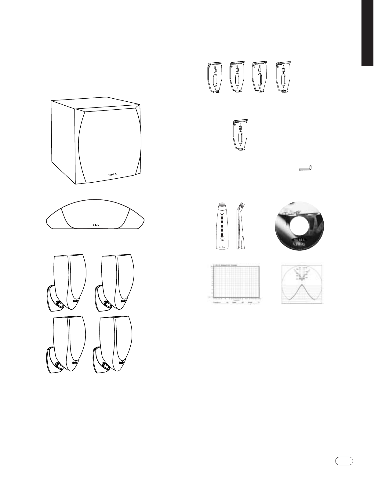
Unpacking the System
Carefully unpack the system. If you suspect damage from
transit, report it immediately to your dealer and/or delivery
service. Keep the shipping carton and packing materials for
future use. Open the package and verify the following contents:
• (1) Modulus II Powered Subwoofer
• (1) Modulus II Center Channel Speaker
• (4) Modulus II Satellite Speakers (With Attached Base)
• (4) Modulus II Wall-Mount Brackets (Attached to Base of
Satellites)
• (1) Wall-Mount Bracket With Bubble Level for Use as Mounting
Template.
• Hex Wrench
(Located Behind Rubber Cap of Satellite Base)
• Warranty Statement
• (1) R.A.B.O.S. Kit, Containing:
-1
-2
-3
-4
-5
-6
-7
-8
-9
-10
-11
-13
-15
-18
U-R
Batt
Sound-Level Meter R.A.B.O.S. Test CD
Graph Templates Bandwidth Selector
ENGLISH
2
MODULUS II HOME THEATER SYSTEM
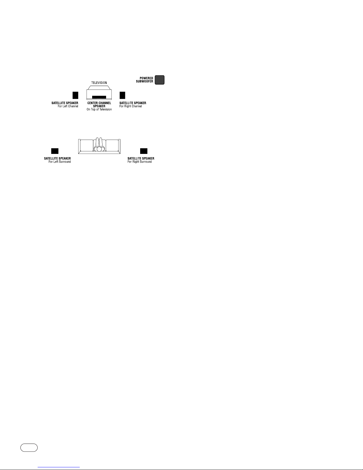
Before deciding where to best place your speakers, survey your
room and study Figure 1.
FIGURE 1 – In this overhead view of a typical installation, satellite
speakers are used to reproduce sound for the front and surround
channels.The center channel reproduces sound and dialog.The
powered subwoofer provides extended bass for effects and music.
P
LACEMENT
NOTE:The satellite speakers can be placed directly on a shelf,
or mounted on a wall using the built-in base/bracket.
CAUTION:The rubber feet can under certain conditions smudge
or discolor light colored and delicate surfaces. Please place a
protective mat or coaster under the rubber feet to prevent
marking or discoloration.
Front Left and Right Channels
For front left and right channels,place one satellite to the left
and another to the right of the television, as shown in Figure 1.
Since the speakers are magnetically shielded, you can place them
very close to the TV without worrying about the magnetic field
distorting the picture.
Center Channel
For the center channel, place the speaker directly on top of, or
below, your television. Use a shelf, if the television does not
provide a stable platform.
Surround Channels
For surround left and right channels, place one speaker on the
left and another on the right, to the sides of or behind the
listening area.
Subwoofer
Since the installation of a subwoofer can be somewhat more
complicated than installing full-range speakers, it is essential
that you read this section very carefully prior to connecting the
subwoofer to your system. Should you have questions relating to
installation, it is advisable to call your Infinity dealer for advice.
The performance of the subwoofer is directly related to its
placement in the listening room and how you align the subwoofer
with the satellite speakers. Setting the volume of the subwoofer in
relation to the left and right speakers is also of critical
importance because it is essential that the subwoofer integrate
smoothly with the entire system. Setting the subwoofer’s volume
level too high will result in an overpowering, boomy bass. Setting
the volume level too low will negate the benefits of the
subwoofer.
Here are several additional facts on installation that may prove
useful. It is generally believed that low frequencies (below
125Hz) are nondirectional and, therefore, placement of a
subwoofer within any listening room is not critical.While in
theory it is true that the larger wavelengths of extremely low
frequencies are basically non-directional, the fact is that, when
installing a subwoofer within the limited confines of a room,
reflections, standing waves and absorptions generated within the
room will strongly influence the performance of any subwoofer
system. As a result, specific location of the subwoofer becomes
important, and we strongly recommend that you experiment with
placement before choosing a final location. Placement will
depend upon your room (for example, whether or not your room
permits placement of the subwoofer near either satellite) and the
amount and quality of bass required.
The R.A.B.O.S.guide, which begins on page 9, will also assist you
in optimizing bass response for your room.
P
LANNING
Y
OURSYSTEM
3
MODULUS II HOME THEATER SYSTEM
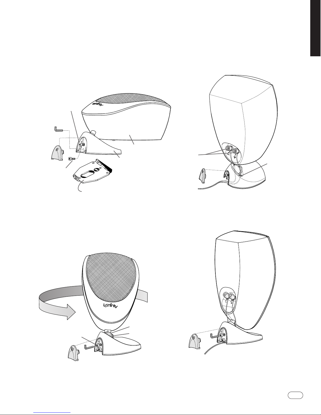
For Shelf Placement
1. Remove the Modulus satellites from the box. Remove rubber
cover from the base and pull out Allen wrench.
NOTE: To prevent damage to the mounting ball, do not rotate the
speaker unless the adjustment screw has been loosened.
2. Use the Allen wrench to loosen the adjustment screw
(as necessary) to allow the mounting ball on the speaker to turn
freely in the cup restraint.
3. Run the speaker wires in through the rear of the base and
up through the speaker wire holes on the left and right sides
of the cup restraint (see page 5,Figure 9 for wire connections).
4. Rotate speaker on its base into the shelf placement position as
shown below.Tighten the adjustment screw with the Allen wrench
(securing the speaker in position) and replace the cover.
Adjustment
Screw
Allen Wrench
housed
in Base
Rubber
Cover
Mounting Plate Screw
Base
Mounting Plate shown removed from Base.
The Mounting Plate is used to secure the
Modulus to a surface in a fixed position
such as for wall-mounting or on an
uneven surface.
Speaker
Adjustment Screw
Speaker
Mounting Ball
Cup Restraint
Connector Posts
Speaker
Wire Hole
I
NSTALLING THE
S
ATELLITES
F
IGURE 2
F
IGURE 4
F
IGURE 5
F
IGURE 3
ENGLISH
4
MODULUS II HOME THEATER SYSTEM
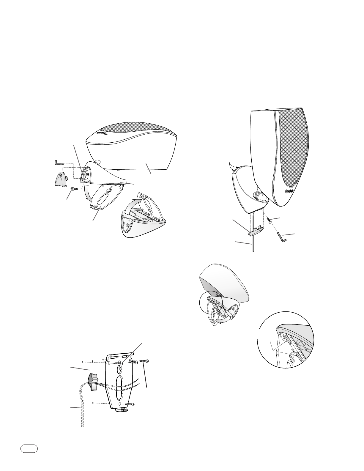
For Wall-Mounting
Note: The customer is responsible for the correct selection
and use of mounting hardware (available through hardware
stores) that will ensure the proper and safe wall-mounting of
the speakers.
1. Remove the Modulus from its box. Remove rubber cover from
the base and pull out Allen wrench. Use Allen wrench to remove
mounting plate screw and remove mounting plate from base.
2. Secure the mounting plate to a wall stud using 4 screws with a
minimum 30 mm length. If fastened to sheetrock or wallboard with
a minimum 12 mm depth, use screws with plastic inserts or
anchors.Do not mount directly to sheetrock or wallboard without
plastic inserts or anchors. One of the mounting plates in the
Modulus system has a built-in bubble level for leveling while
securing to the wall.This mounting plate should be used as a
template for mounting the mounting plates that do not include a
bubble level.
2a. In cases where you would like to run the speaker wires
through the wall, the mounting plate has a center hole for wire
access.
3. Run the speaker wires through the base as shown below.Attach
base to mounting plate by slipping the returns on the underside of
base into slots on the top of the mounting plate and hinging the
base downward. Secure base by inserting and tightening mounting
plate screw.Tighten adjustment screw, fixing the speaker in
position.
4. Insert the Allen wrench back into holder in base
and attach rubber cover.
Viewed from below
Note:
Base has returns
that grab Mounting Plate
Returns on
underside of Base
Rubber Cover
Speaker Wires
Adjustment Screw
Allen Wrench
Speaker Wires
Hole in the wall
WALL
Bubble Level
FIGURE 7
Wood screws
(not included)
FIGURE 8
Adjustment
Screw
Allen Wrench
housed
in Base
Rubber
Cover
Mounting Plate Screw
Base
Speaker
Mounting Plate
F
IGURE 6
I
NSTALLING THE SATELLITES
 Loading...