

Page 1

OWNER'SMANUAL
Page 2

UNPACKING
1. Carefully unpack the speakers. If you suspect damage from
transit, report it immediately to your dealer and/or delivery
service. Keep the shipping carton and packing materials for
future use.
2. Verify that the package includes the following items:
-
(2) L-MPS Speakers
-
(2) Mounting Brackets and Hardware
-
(1) Owner’s Manual
-
(2) Speaker Bases
PLANNING YOUR SYSTEM
Infinity L-MPS (Large Multi-Purpose Satellite) speakers are
specific components for your home entertainment system.
You can use them to reproduce sound for the front or rear
channels, or both.
To help plan your system, study the drawing (shown in
Figure 1) to determine a placement that best suits your needs.
FIGURE 1.
In this overhead view of a typical 6-piece home enter-
tainment system, Minuette L-MPS speakers are used to reproduce
sound for the front and rear (surround) channels. A Minuette Center
Channel speaker is added to enhance center-channel dialogue. An
optional Infinity Powered Subwoofer is used to prooide extra bass
for
effects
and music.
l
MINUEllE
L-MPS
SPEAKER
For Left Channel
TELEVISION INFINITY POWERED
SUBWOOFER
(optional)
MINUETTE
CENTER
CHANNEL SPEAKER
On Top Of Television
For Center Channel
4
MINUEllE
L-MPS
SPEAKER
For Right Channel
MlNUEllE
L-MPS
=
MINUEllE
L MPS
EEJ
SPEAKER
Surround
w
l
Right Rear
Surround
PLACEMENT
FRONT
PIACEMENT
Using speaker stands or bookshelves, place a pair of Minuette
L-MPS speakers on their bases (included) and place on either
side of the television. They can be aimed at the viewing
audi-
ence, if desired (see Figure 1). Experiment with different
place-
ment to find the most pleasing effect for your system.
NOTE: Minuette L-MPS speakers may be placed
wrtically
on their
bases or horizon tally (see Figures 2 and 3 on the next page).
For wall and ceiling mounting, Miiuette L-MPS speakers can
be installed in a variety of ways, as shown in Figures 4
through 7 (on the next two pages). You can mount the
speakers directly with screws (not included), or use the enclosed
mounting brackets. Locate a stud for secure mounting. Use
heavy-duty screws with long threads so there is an adequate
number of threads holding the speaker (or speaker/bracket) to
the wall. Test the mounting thoroughly before final installation.
REAR PLACEMENT
For rear channel placement, follow the same procedure for
front placement, except place a pair of L-MPS speakers
slightly behind or ahead and above either side of the viewing
audience (see Figure 1).
Page 3
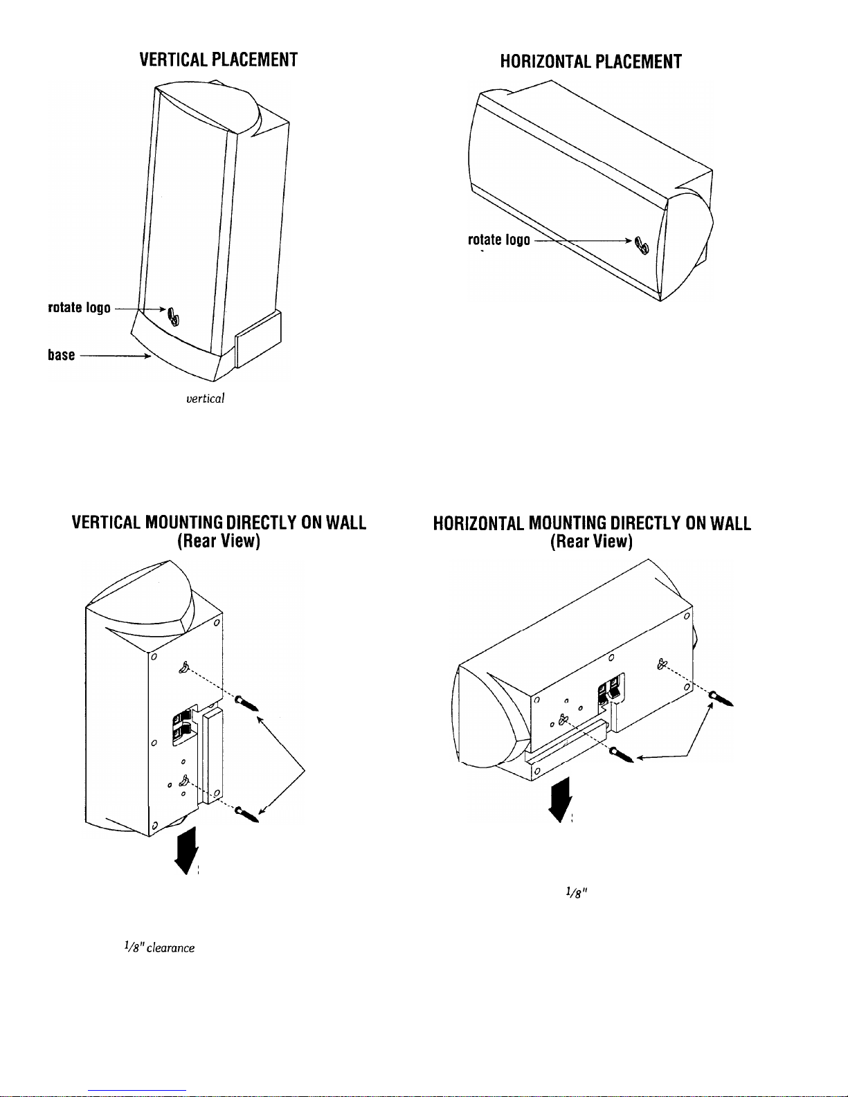
VERTICAL PLACEMENT
HORIZONTAL PLACEMENT
FIGURE 2. Free-standing
uertical
placement of L-MPS speaker.
NOTE: Use the enclosed base for added stability.
VERTICAL MOUNTING DIRECTLY ON WALL
(Rear View)
Wood Screws
(fasten to
wall stud)
A
1
t
Slide
Speaker Down
Onto Wood Screws
FIGURE 4. For vertical mounting of the L-MPS speaker directly
on a wall, fasten the wood screws (not included) to a desired wall
stud, leauing a
1/8”clearance
between the screw head and the wall.
Rotate the L-MPS speaker vertically, align the keyholes on the rear
of the speaker with the wood screws, and slide speaker down.
FIGURE 3. Free-standing horizontal placement of L-MPS speaker.
HORIZONTAL MOUNTING DIRECTLY ON WALL
(Rear View)
0
7
Wood Screws
(fasten to
wall stud)
Slide
Speaker Down
Onto Wood Screws
FIGURE 5. For horizontal mounting of the L-MPS speaker
directly on a wall, fasten the wood screws (not included) to a
desired wall stud, leauing a
l/8”
clearance between the screw head
and the wall. Rotate the L-MPS speaker horizontally, align the
keyholes on the rear of the speaker with the wood screws, and
slide speaker down.
2
Page 4
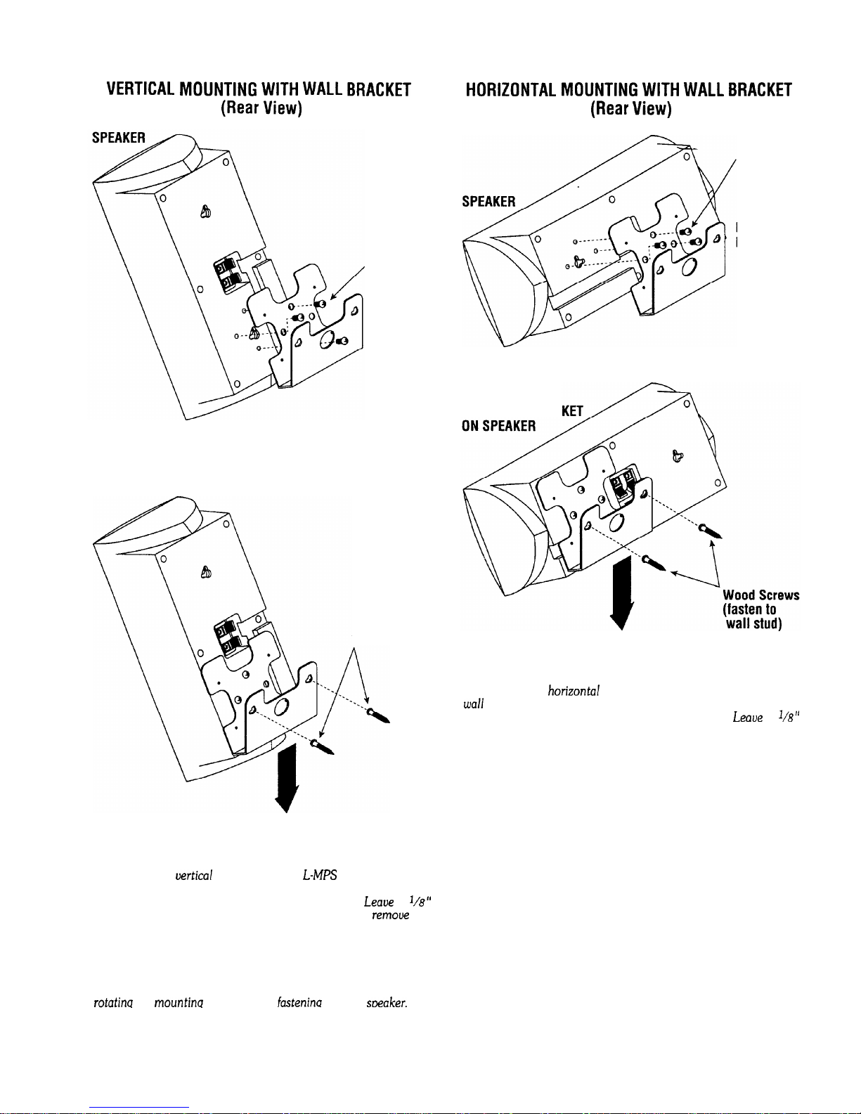
VERTICAL MOUNTING WITH WALL BRACKET
(Rear View)
(3)
Screws
(fasten to
speaker)
MOUNTING
BRACKET
MOUNTING BRACKET
ON SPEAKER
Wood Screws
(fasten to
wall stud)
Slide Speaker With Bracket
Down Onto Wood Screws
FIGURE 6. For
uertical
mounting of the
L-MB
speaker on a wall
using the enclosed bracket, fasten the bracket (as shown) with
wood screws (not included) to a desired wall stud.
Leaue
a
I/B”
clearance between the screw head and the wall. Then,
remoue
the
bracket and firmly attach it to the back of the speaker using the
enclosed screws. Finally, align the bracket’s keyholes with the
wood screws in the wall, and slide the speaker (with bracket) down.
NOTE: The aboue illustration shows the L-MPS speaker being
mounted with a downward tilt. Other orientations are possible by
rotatina
the
mountina
bracket before
fastenina
it to the
smaker.
HORIZONTAL MOUNTING WITH WALL BRACKET
(Rear View)
(3) Screws
(fasten to
speaker)
MOUNTING
BRACKET
MOUNTING BRAC
Slide Speaker With Bracket
Down Onto Wood Screws
FIGURE 7. For
horizonta!
mounting of the L-MPS speaker on a
wall
using the enclosed bracket, fasten the bracket (as shown) with
wood screws (not included) to a desired wall stud.
Leaoe
a
l/B”
clearance between the screw head and the wall. Then, remove the
bracket and firmly attach it to the back of the speaker using the
enclosed screws. Finally, align the bracket’s keyholes with the
wood screws in the wall, and slide the speaker (with bracket) down.
NOTE: The aboue illustration shows the L-MPS speaker being
mounted with a downward tilt. Other orientations are possible by
rotating the mounting bracket before fastening it to the speaker.
3
Page 5

WIRING THE SYSTEM
After placing the Miiuette L-MPS speakers, you are ready to wire
your speakers. First turn off all audio system power. Use
high-
quality speaker wire
(#16
gauge
or
heavier) to make your
connec-
tions. Consult the owner’s manuals that
were
included with
your
amplifier,
receiver,
or telebision to confirrn
connection procedures.
Miiuette L-MPS speakers have spring-loaded terminals for easy
wiring. Observe polarities when making speaker connections,
as shown in Rgure 8. Connect each + terminal on the back of
the amplifier, receiver, or
television
to the respective + (red)
terminal
on each Minuette L-MPS speaker. Similarly, connect
the - (black) terminal in the same way.
IMPORTANT! Do not
reuerse
polarities (i.e., + to - or
-
to +) when making connections. Doing so will cause
poor imaging and diminished bass response.
MINUET-l-E L-MPS
MINUETTE CENTER CHANNEL
(Front Left)
(Center)
MINUETTE L-MPS
(Front Right)
A/V Receiver
(Rear Panel)
Left
Riaht
MINUETTE L-MPS
(Surround Left)
+ Surround
Preamp Outputs
Surround
-
L R
B
Stereo RCA Cable
- *-wa1m.-
MINUGMPS
B
(Surround Right)
@
1
wiring diagrams.
Optional Infinity Powered Subwoofer
(Rear Panel)
FIGURE 8. An example of bow to interconnect L-MPS speakers
to an A/V
{audiduideo) receiuer
in a system.
4
Page 6

UNDERSTANDING POWER RATINGS
An A/V (audio/video) receiver with limited power output can
,actually
cause damage to your speakers. When played beyond
its power capability, it will go into clipping. This generates
spurious high-frequency signals which, when routed to the
tweeter, can cause it to overheat
IN
CASE
Before consulting your dealer,
service department, you can perform simple troubleshooting. If
the sound quality is distorted, listen to each speaker separately
to check if the fault is present in both. If it is, then the trouble is
likely to be elsewhere in your system. If the fault is in one
channel only, switch the left and right speaker leads at the
receiver. If the distortion moves to the other speaker, the fault
is not in the speaker.
OF TROUBLE
and fail.
Infinity
service facility or
factoy
Overdriving the power amplifier must be avoided. It is always a
good idea to choose a receiver with more power than you need.
(Refer to power ratings in Specifications below.)
If there is no authorized service facility near you, contact the
Service Department at
Park West, Woodbury, NY 11797, (516) 496-3400, and
describe the problem as specifically as possible. The service
department will advise you what action to take.
Note: Do not ship any parts or whole speakers for service without
prior approval (“Return
enclosing a copy of your original bill of sale and a description of
the problem.
SPECIFICATIONS
L-MPS Speakers
Infinity
Customer Service, 80 Crossways
Authorization”),
and do not ship without
Frequency Response
Crossover
Sensitivity
Nominal Impedance
Power Rating..
Frequency
..................................
................................
...............................................
.....................................
180 Hz - 20
...............................................
..87 dB @
2.85 V,
.15- 80 watts (rms)
kHz
.5 kHz
1
meter
8 ohms
Driver Complement
l/2”
Cabinet Finish
Cabinet Dimensions*
.................( 2)
polycarbonatedome tweeter w/acoustic lens
..........................................................
..10
26.5 cm wide x 11.9 cm high x 9.4 cm deep
7/x1’
3
l/2”
wide x
paper-cone woofers
.black
4V4”
high x 3
* Not including bracket
3/4”
deep
5
Page 7

LIMITED WARRANTY
WHO IS PROTECTED BY THE
WARRANTY3
.
Your Infinity warranty protects the original retail purchaser
and all subsequent owners for a period of five (5)
years (parts
and
labor)
from any failure as a result of original manufacturing
defect so long as: (1) your Infinity loudspeaker was purchased
within the fifty United States or by military personnel from an
authorized military outlet and (2) the original dated bill of sale is
presented whenever service is required during the warranty
period. This warranty does not apply to products purchased
elsewhere; other purchasers should contact their local Infinity
distributor for warranty information.
WHAT DOES THE
INFINITY
WARRANTY COVER?
Except as specified below, this warranty covers all defects in
original materials and workmanship. The following are not
covered: damage caused by accident, misuse, abuse, neglect,
product modification; damage occurring during shipment;
damage caused by failure to follow instructions in the owners
manual, including failure to perform recommended periodic or
routine maintenance; damage resulting from repairs by
someone not authorized by Infinity; claims based upon any
misrepresentations by the seller; and any
Infinity
product on
which the serial number has been altered, defaced, or removed.
WHO PAYS FOR WHAT?
During the period of the warranty, subject to the above
conditions, Infinity will pay all of the
labor
and material
expenses to repair a warrantable defect.
HOW CAN WARRANTY
SERVICE BE OBTAINED?
In the event that your Infinity loudspeaker should require
setice,
you should first contact the Infinity dealer from whom
the product was purchased or, if this is not practical, contact
Infinity directly
(ATTN:
Customer Service) at 80 Crossways
Park West, Woodbury, NY 11797, (516) 496-3400.
We may direct you to an authorized service center for Infinity
products or ask you to send them to us for repair. In either
case, you will have to present your original bill-of-sale to establish warranty coverage. Do not send your speaker to us
without prior authorization from our Customer Service
Department.
You are responsible for transporting your product to either
Infinity or an authorized service center and for payment of all
shipping charges; however, Infinity will pay the return shipping
charges (in the event you return the product to us) if the
repairs are covered by warranty,
If you experience difficulty in transporting you product or are
in need of packing materials, please advise us and we may be
able to suggest alternative procedures and/or provide adequate
packing materials.
LIMITATION OF IMPLIED WARRANTIES:
All implied warranties, including fitness for a particular
purpose and merchantability are limited in duration and length
to the warranty period for your product.
LIMITATION OF INCIDENTAL OR CONSEQUENTIAL DAMAGES:
Infinity is not responsible for any incidental or consequential
damage of any kind. Our liability is limited to the repair or
replacement, at our option, of a defective product.
Some states do not allow limitations on how an implied
warranty lasts and/or do not allow the exclusion of incidental
or consequential damage, so the above limitations or exclu-
sions may not apply to you.
This warranty gives you specific legal rights and you may also
have other rights which
vary
from state-to-state.
NOTE: In the event that there is a difference between this
warranty and the provisions in any advertisements, product
brochures or packaging cartons, the terms of this warranty
will prevail.
0
1997,
Infinity
Systems, Inc., 80 Crossways Park West, Woodbury,
NY
11797
U.S.A.
(5 16) 496-3400 l FAX: (516) 496-4868
wwu.infinitysystems.com
Infinity constantly strives to update and improve existing products, as well as create new ones. therefore the specifications and
construction detak in this and related infinity publications are subject to change without notice.
PIN 939-8007
Page 8

OWNER’S MANUAL
Page 9

UNPACKING
CONNECTING
THE SYSTEM
POSITIONING
OF THE
SUBWOOFER
A WORD OF
ADVICE
Inspect your subwoofer carefully after unpacking. If it has been damaged in transit,
call your dealer or the trucking firm that delivered it for instructions on how to file
a claim.
NOTE: Make sure all equipment is turned off before making connections.
CONNECTING
THE
SUBWOOFER WITH SATELLITES
The Micro Subwoofer is a passive subwoofer (does not have a power amplifier built
into the enclosure) and can be used with any quality stereo integrated amplifier,
receiver, or separate components. Observe the following procedures for installing the
subwoofer.
1. Connect Left and Right OUTPUTS of your amplifier to the corresponding Left and
Right INPUT terminals on the subwoofer.
2. Connect satellites to the Left and Right OUTPUT terminals on the subwoofer.
3. Observe polarity.
4. Refer to
diagram below
for hook-up instructions.
DIAGRAM
SATELLITE
LEFT
SUBWOOFER
(rear)
AMPLIFIER
NOTE: You may also connect your amplifier
outixt
(Left & Right) directly to the satellites, then connect the satellites to the subwoofer
Left 8 Right inputs. Observe polarity.
The performance of the Micro subwoofer is directly related to it’s position in the
listening room. At times, moving the subwoofer merely an inch or two can make a
significant difference in the way it will sound.
If bass response is judged to be light, move the subwoofer closer to a comer. The comer
enhances the subwoofer’s ability to couple to the room and will create more bass. If
bass response is judged too heavy, move the subwoofer away from the wall or comer.
The subwoofer does not have to be positioned between the two satellites for best overall
sonic balance. It may be placed anywhere it sounds best. Low frequencies are nondirectional which means you can place the subwoofer either in the middle or to the
left or right of the satellites and obtain optimum bass balance. Experimentation by
positioning the subwoofer in several different locations will reveal which position
yields optimum results.
NOTE: The subwoofer may be mounted vertically or horizontally, but do not mount
it so the port faces the floor. The port must remain unobstructed for proper
performance.
It is not advisable to operate the Micro Subwoofer (and satellites) with the tone controls
of your
stereo
system set to maximum boost. In fact, it is always good practice to keep
the tone controls set to reasonable boost levels because excessive bass and treble can
damage your satellites as well as the subwoofer.
Page 10

ACOUSTIC
FEEDBACK
UNDERSTANDING
MIN/MAX
POWER
RATINGS
SPECIFICATIONS
IN CASE OF
TROUBLE WITH
YOUR STEREO
SYSTEM
The volume control settings on your stereo preamplifier, receiver or integrated
amplifier is not an indication of the overall volume level of your system. The only
important consideration is the loudness level at which the system can be played
regardless of where the volume control is set.
Always turn down the volume when changing a record or switching inputs from
AM to FM, phono or CD operation. Excessively loud transients (loud pops and clicks)
can damage your speakers. Whenever changing plugs, cables, etc., always turn off
your system. This will prevent transients form reaching your speakers and also
prevents electrical energy from reaching you. Keep electrical connections out of reach
of children.
Acoustic feedback is created when sound waves from speakers reach a phono turntable
and are fed back through the phono pickup to the power amplifier. It is a never ending
cycle which can cause distortion across the entire audio band. To avoid acoustic
feedback problems, place your turntable on a heavy, solid support and as far away
from the speakers as possible. At times, isolating the turntable with special rubber
mounts may aid in reducing this form of distortion.
An amplifier with limited power output can actually cause damage to your speakers.
A lower powered amplifier, when played beyond it power capability, will clip. This
generates spurious high frequency signals which, when routed to the tweeter, can cause
it to overheat and fail. It is for this reason that choosing an amplifier with higher power
is always a wise choice.
MICRO SUBWOOFER
Power Rating
. . . . . . . . . . . . . . . . . . . . . . . . . . . . . . . . . .
.lO
100 watts per channel, RMS
Frequency Response . . . . . . . . . . . . . . . . . . . . . . . . . . . . . . . . . . . . . . . . .
.45
Hz to 150 Hz
Sensitivi
In
.
.90 dB @
2.8 volts, 1 meter
Nominal
peh’ance’::::::::::::::::::::::::::::::::.
.
.compatiblewith4ohms
Note that you can use your amplifier’s two channels of information for simple troubleshooting. If the sound quality is distorted, listen to each speaker separately to check
if the fault is present in both. If it is, then the trouble is likely to be elsewhere in your
system. If the fault is in one channel only, reverse the outputs from your amplifier to
the speakers (right-to-left and left-to-right). If the distortion moves to the other
channel, the fault is not in the speaker. (This technique may also be used to locate
a fault between the signal source and preamp / receiver and/or between preamp
and power amp(s).If you have been unsuccessful in locating the specific source of
trouble (or if you have located it, but have been unable to correct it), make inquiries
in the following order:
+
Consult the Authorized Infinity Dealer from whom you purchased the system.
Infinity Dealers are audio specialists and can be of great assistance.
DECLARATION OF CONFORMITY
NOTE: DO NOT SHIP ANY PARTS OR WHOLE SPEAKERS FOR SERVICE
WITHOUT PRIOR APPROVAL (“RETURN
AUTHORIZATION”),
AND DO NOT
SHIP WITHOUT ENCLOSING A COPY OF YOUR ORIGINAL BILL OF SALE.
Page 11

1995
0
Infinity strives constantly to update and improve
@
Printed on recycled paper
and
Infinity
construchon detdilb
Systems, Inc. 20630 Nordhoff St., Chatsworth,
Infinity
We get you back to what it’s all about.
(818) 407-0228 l FAX (818) 709-0486
existing
in this and related Infinity publications are subject to change without notice.
products, as well as create new ones, therefore, the specifications
MADE
IN DENMARK
M&k.
CA
91311
P/N 9471095
 Loading...