

Page 1
Thank youfor purchasing an Infinity Kappa Perfect compo-
nent system. The Kappa Perfect6.1 has been engineered to provide
the most accurate sonic reproduction possible. Over the years, we
at Infinity have listened to hundreds of automotive speakers and we
think these are the best. We hope you agree.
This manual includes information that will make your installation
as simple and trouble-free as possible. It also provides detailed technical information that will help an experienced installer optimize
speaker placement and crossover adjustment. Please study this
manual before you begin your installation. Remember to send in
your warranty registration card, and keep your sales receipt somewhere safe in case you need warranty service.
®
KAPPASERIES
6.5" Component System
INSTRUCTIONS
6.1
Kappa Perfect 6.1 OM 10/12/99 2:15 PM Page 1
Page 2
IMPORTANT
Installation of automotive stereo components can require extensive experience performing a variety of mechanical and electrical procedures. Although these instructions
explain how to install a Kappa Perfect6.1
component system in a general sense, they
do not show the exact installation method
for your particular car. If you feel you may
not have the necessary tools or experience,
ask your authorized Infinity car-audio dealer
about professional installation options.
WARNING
Playing loud music in your automobile
can permanently damage your hearing as
well as hinder your ability to hear traffic. We
recommend listening at low volume while
driving. Infinity accepts no liability for hearing loss, bodily injury or property damage
resulting from use or misuse of this product.
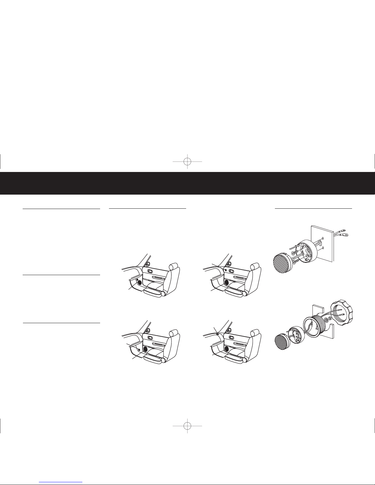
SPEAKER PLACEMENT
Figures 1–4 show possible speak er placements in the order of most desirable to
least desirable. Kick-panel mounting will
provide the best staging and imaging in
most vehicles.
A NOTE ABOUT SYSTEM PERFORMANCE
For the best performance possible, the
Kappa Perfect6.1 should be used with a
two-channel amplifier with output power of
at least 35W RMS per channel. The passive
crossover contains impedance-compensating
circuitry and has been computer-optimized
for the flattest possible frequency response
with the tweeter flush-mounted on axis
with the listener. The combined responses
of the speakers and passive crossover
constitute 4th-order Linquitz-Riley
acoustic
alignment and cannot be duplicated
with
any electronic crossover currently available
for car-audio use. Consequently, bi-amping
the Perfect6.1 with an electronic crossover
is not recommended.
TWEETER INSTALLATION
TWEETER
on dash
WOOFER
in factorydoor location
TWEETER
on kick panel
WOOFER
in factorydoor location
TWEETER
and
WOOFER
on kick panel
WOOFER
in factorydoor location
TWEETER
in high/forward
location on door
Fig 1
Fig 3
Fig 2
Fig 4
Figure 1.
Mounting the woofer and tweeter in
the kick panels
Figure 2.
Mounting the woofer in the door and
the tweeter in the kick panel
Figure 3.
Mounting the woofer and tweeter in
the doors
Figure 4.
Mounting the woofer in the door and
the tweeter in the dash
1
2
–
+
1
2
Figure 5.
Surface-mounting the tweeter
Figure 6.
Flush-mounting the tweeter
Kappa Perfect 6.1 OM 10/12/99 2:15 PM Page 2
Page 3

WOOFER INSTALLATION
Figure 7.
Mounting the woofer where
there is no factory speaker location
Figure 8.
Mounting the woofer in
standard 5-1/4" holes (in many
Japanese and American automobiles)
Figure 9.
Mounting the woofer in
165mm holes (in many European
and American automobiles)
ELECTRICAL CONNECTIONS AND CROSSOVER ADJUSTMENTS
®
TWEETER LEVEL
–4dB
J1 J2
J1
J2
0dB
+5dB
KPX00
J1
J2
Tweeter level
+5dB
Tweeter level
0dB
(default)
To woofer
To tweeter
To amplifier
speaker output
J1
J2
Tweeter level
–4dB
J1
J2
Figure 10.
Connecting the speakers and the amplifier
to the crossover
J1
®
Figure 11.
Adjust the crossover using the jumpers
provided
SPECIFICATIONS
System
Frequency Response: 75Hz – 23kHz, ±3dB
Power Handling: 100W RMS, 400W Peak
Nominal Impedance: 4 Ohms
Sensitivity: 90dB
Crossover Frequency: 3.5kHz, 24dB/oct.
Linquitz-Riley Acoustic
Thiele and Small Parameters
Woofer Tweeter
Revc: 3.45 3.31
Levc: 0.37 0.02
Sd: 0.0113 0.0005
BL: 6.37 1.99
Vas: 11.43 0.0016
Cms: 630.36 44
Mms: 18.94 0.3064
Mmd: 18.25 0.3
Fs: 46.05 1370.65
Qms: 3.44 5.4
Qes: 0.465 2.19
Qts: 0.41 1.56
T op-Plate Thickness: 9/32" (7 .1 15mm) na
Voice-Coil Length: 9/16" (14mm) na
Voice-Coil Diameter: 1-1/2" (38.1mm) 1" (25.4mm)
Xmax: 1/8" (3.44mm) na
Mounting Depth: 2-3/4" (70mm) 1" (25.4mm)
Cut-Out Diameter: 5-1/16" (129mm) 1-3/4"
(45mm)
Kappa Perfect 6.1 OM 10/12/99 2:15 PM Page 3
Page 4

DECLARATION OF CONFORMITY
We, Infinity Systems A/S
Kongevejen 194B
DK-3460 Birkerød
DENMARK
Steen Michaelsen
Infinity Systems A/S
Birkerød. DENMARK. 9/99
declare in own responsibility, that the product described in this owner’s manual is in compliance with
technical standards:
EN 50081-1:1992
EN 50082-1:1992
®
Infinity Systems, Inc. • 250 Crossways Park Drive
Woodbury, NY 11797 USA • (800) 553-3332
FAX (516) 682-3523 • Part No: KAP6.1OM
A Harman International Company
2 re u ncy 100
500
1k Hz 5k
10k
20k0 Fqe
Sound Pressure Level
dB spl
110
100
90
80
70
60
50
40
30
Deg
180
135
90
45
0
-45
-90
-135
-180
C
Kappa Perfect6.1 (flat setting)
Kappa Perfect6.1 (+5dB setting)
Kappa Perfect6.1 (–4dB setting)
20 Fre quency 100
500
1k Hz 5k
10k
20k
Sound Pressure Level
dB spl
110
100
90
80
70
60
50
40
30
Deg
180
135
90
45
0
-45
-90
-135
-180
C
Kappa Perfect6.1 Tweeter (flat setting)
Kappa Perfect6.1 Woofer
Kappa Perfect6.1 Tweeter (–4dB setting)
Kappa Perfect6.1 Tweeter (+5dB setting)
20 Fre quency 100
500
1kk Hz 5k
10k
20k
Impedance Measurement Ohms
0.3
1.0
3.0
10.0
30.0
Deg
180
135
90
45
0
-45
-90
-135
-180
C
Kappa Perfect6.1 (flat setting)
Kappa Perfect6.1 (+5dB setting)
Kappa Perfect6.1 (–4dB setting)
20 Fre quency 100
500
1k Hz 5k
10k
20k
Impedance Measurement Ohms
0.3
1.0
3.0
10.0
30.0
Deg
180
135
90
45
0
-45
-90
-135
-180
C
Kappa Perfect6.1 Tweeter
Kappa Perfect6.1 Woofer
20 Fre quency 100
500
1k Hz 5K
10K
20K
C
Passive Network Transfer Function:dB
dB
-40
-50
-60
-70
-80
-90
-100
-110
-120
Kappa Perfect6.1 Woofer
Kappa Perfect6.1 Tweeter (flat setting)
Kappa Perfect6.1 Tweeter (–4dB setting)
Kappa Perfect6.1 Tweeter (+5dB setting)
SYSTEM RESPONSE CURVES
Figure 12.
System frequency response
Figure 13.
Component frequency response
Figure 14.
System impedance
Figure 15.
Woofer and tweeter impedance
Figure 16.
Network response (considering speaker
impedances and resistive load)
Kappa Perfect 6.1 OM 10/12/99 2:15 PM Page 4
 Loading...