

Page 1
®
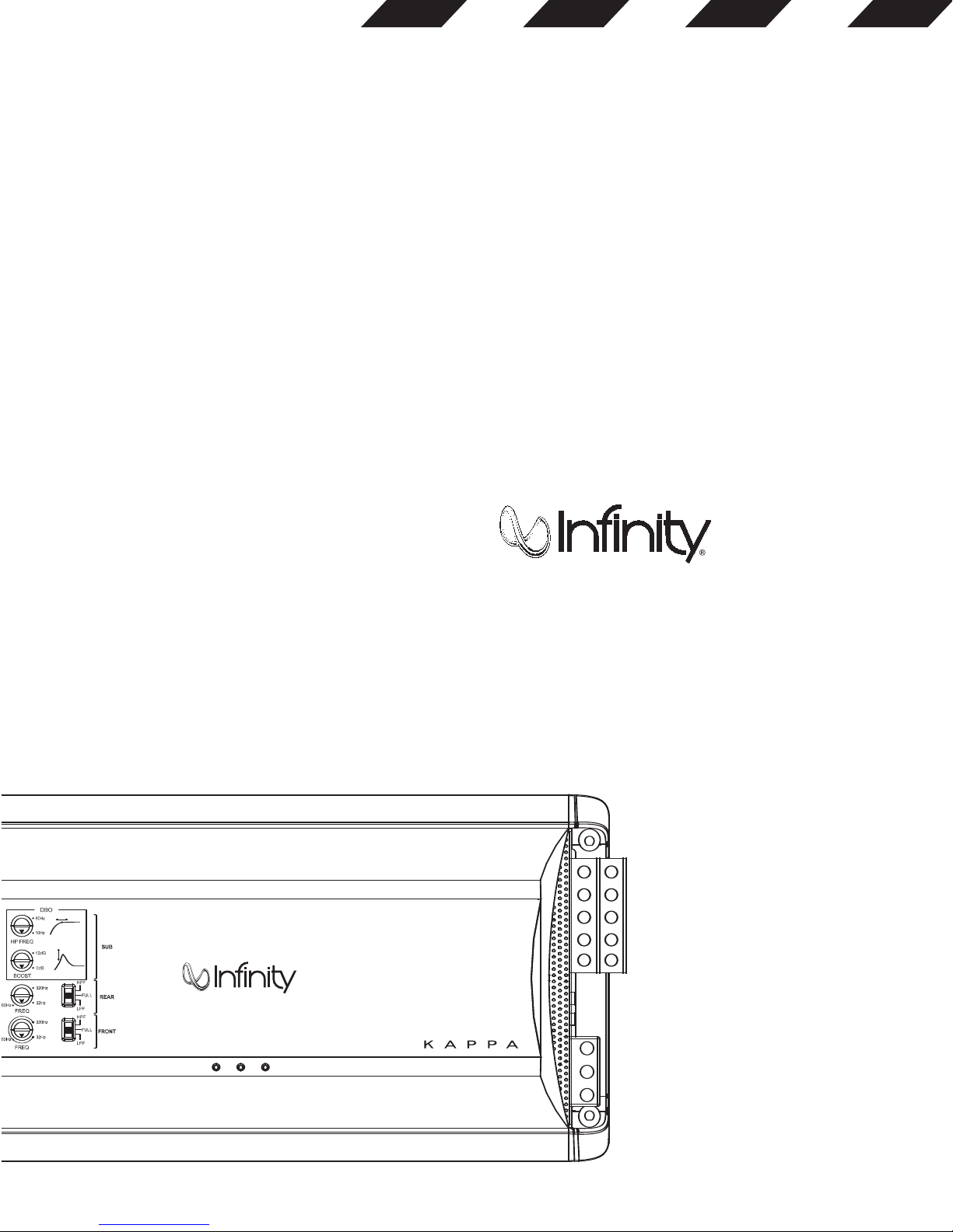
KAPPA
KAPPA®FIVE
Page 2
¡
1
2
B
5
6
7
8
E
IF G H
A
B
L
BB
BB
F
R
O
N
T
R
E
A
R
RRSUBL
34
9 A
C
D
K
A
B
C
ABCDEF
J
3x
4x
1x
1x
3a
Page 3

Installation Warnings and Tips:
Factory Bolt Ring Connector
Ground Wire
Note: Remove any paint
below ring connector.
Star Washer
• Disconnect the negative (–) lead from your vehicle’s
battery.
• At the installation sites, locate and make a note of all
fuel lines, hydraulic brake lines, vacuum lines and
electrical wiring. Use extreme caution when cutting
or drilling in and around these areas.
• Choose a safe mounting location away from moisture.
• Make sure there is sufficient air circulation at the
mounting location for the amplifier to cool itself.
• Mount the amplifier,using the supplied hardware.
Specifications
• 50W RMS x 4 channels & 200W RMS x 1 channels
@ 4 ohms <1% THD + N*
• 75W RMS x 4 channels & 300W RMS x 1 channels
@ 2 ohms <1% THD + N*
• Total peak power: 1200W
• Frequency response: 10 to 75kHz & 20 to 320Hz (–3dB)
• Maximum input signal: 6V*
• Maximum sensitivity: 200mV*
• THD + N:0.05%
• Signal-to-noise ratio: 85dBA (reference to 1 watt)
• Signal-to-noise ratio: 100dBA (reference to rated power)
* CEA-2006A-compliant
0
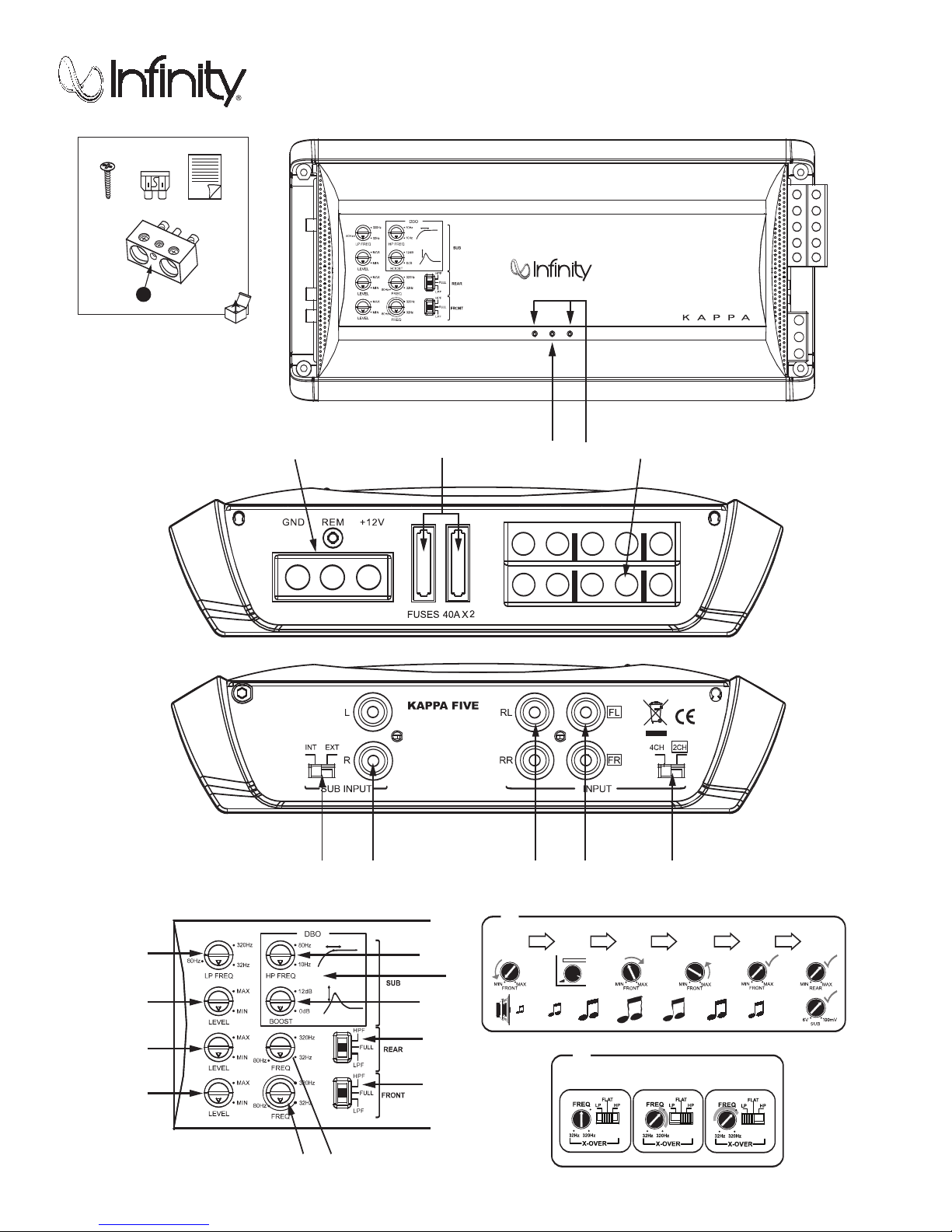
Speaker Output Connectors
• Connect the speakers to these terminals,observing
proper polarity. Gold screws indicate +, and silver
screws indicate –.
• Five-channel operation: Connect the front left
speaker to the Front L+ and L– terminals and
the front right speaker to the Front R+ and R–
terminals.Repeat for the rear speakers, using
the Rear L+ and L– terminals,and the Rear R+
and R– terminals.Connect the subwoofer to the
Sub+ and Sub– terminals.
• Four-channel operation: Connect the stereo speakers
to the Front terminals, as above.The single speaker,
into which the amplifier’s rear channels will be
bridged, must be connected to the Rear terminals
marked “B.” Connect the subwoofer to the Sub+ and
Sub– terminals.
ee-channel (bridged) operation: Connect one
hr
T
•
speaker t
the o
Connec
erminals.
t
ther speaker t
ont terminals marked “B.”Connect
r
o the F
o the Rear t
er to the Sub+ and Sub–
oof
t the subw
erminals marked “B.”
• Minimum speaker impedance for stereo operation is
2 ohms. Minimum speaker impedance for bridged
operation is 4 ohms. Minimum subwoofer impedance
is 2 ohms.
1
2
s
e
s
Fu
Replace onl
•
th the same type and rating.
y wi
Power Input Connectors
• +12V: Connect to the positive terminal of the vehicle’s
battery. 4 AWG wire is recommended.Install an
appropriate fuse holder and fuse (80A minimum) within
18' of the battery. Make sure the wire is not damaged
or pinched during installation.Install protective
grommets when routing wires through the firewall
or other sheet metal.
• GND: Connect to the vehicle’s chassis. Refer to
the illustration below.
3a
4 AWG Adapter
• For power wire longer than 4' (1.2m),4 AWG wire is
recommended. Use the adapter to make the connection
according to the illustration below.
3
Protect LED
• Illuminated under any of the following fault
conditions: battery over/under voltage,short
circuit in speaker wires,amplifier is too hot,
amplifier’s output circuit has failed (DC voltage
present in the amplifier’s output).
4
Power On LEDs
• Illuminated when the amplifier is on.
5
Subwoofer Low-Pass Filter
Frequency Control
• 12dB/Octave low-pass filter,variable from
32Hz to 320Hz.
• See Jfor the adjustment procedure.
6
Subwoofer Input-Level Control
• Used to match the SUB input of the amplifier to the
ce unit.
for the adjustment procedure.
ut-Level Control
p
7
ou
• See
Re
t of the sour
tpu
J
r In
a
• Used to match the rear input level of the
amplifier to the output level of the source unit.
J
See
or the adjustment pr
•
8
9
A
B
f
Front Input-Level Control
•
the ou
adjustment pr
el of the source unit. See
v
t le
tpu
ocedur
e.
h the input level of the amplifier to
tc
o ma
Used t
Front Crossover-Frequency Control
ve crossover, variable from 32Hz to 320Hz.
a
t
12dB/Oc
•
Rear Crossover-Frequency Control
ve crossover, variable from 32Hz to 320Hz.
a
t
12dB/Oc
•
J
See
or the adjustment pr
f
DBO: Variable Subsonic High-Pass
ocedur
ocedur
e.
J
f
e.
Filter With Variable Boost (Q)
ers in tuned (vented) enclosures,set
oof
or w
F
•
the fr
enclosur
equenc
e’
s r
o a value 10Hz below the
ol t
y contr
esonance (t
uned) frequency.
• For woofers in sealed boxes, set the frequency control
to any value you prefer between 30Hz and 50Hz.
t the Boost contr
Se
•
being car
oof
our w
y
ol according t
o apply enough boost to damage
t t
ful no
e
er(s).
o your preference,
or the
A Boost (Q) control provides up to 12dB of boost,
slightly above the high-pass filter’s frequency.
See Bfor appropriate settings.
B High-Pass Filter Frequency control, variable
between 10Hz and 80Hz.See Bfor appropriate
settings.
C
Rear Crossover-Filter Selector
• LP: Select for subwoofer(s) or to provide a low-pass
filter for separate mid-bass speakers.The subsonic
filter will provide a high-pass filter for separate
mid-bass speakers.
• FLAT: Select for full-range speakers when
no subwoofer will be used in the system.
• HP: Select for midrange speakers or full-range
speakers when a subwoofer is used in the system.
D
Front Crossover-Filter Selector
• LP: Select for subwoofer(s).
• FLAT:Select for full-range speakers when no
subwoofer will be used in the system.
• HP: Select for midrange speakers or full-range
speakers when a subwoofer is used in the system.
E
Input Selection Switch
• If you are using RCA-type inputs and the source unit
has a subwoofer output,and you have connected it to
the SUB input, set this switch to the EXT position.
Otherwise, set it in the INT position.
F
Subwoofer Input Connector (RCA)
• Connect to subwoofer RCA-type outputs from the
source unit or signal processor.
G
Rear Input Connectors (RCA)
• Connect to rear RCA outputs from the source unit,
or signal processor.
H
Front Input Connectors (RCA)
• Connect to front RCA outputs from the source unit
or signal processor.
I
Rear Input Signal Selection Switch
• If your source unit has only front RCA-type outputs
and they are connected to the amplifier’s Front input
connectors,move this switch to the FRONT setting.
If your source unit has 4 RCA-type outputs,leave it
in the 4CH position.
J
Setting Gain (Input Level)
A Turn all Gain controls counterclockwise to
6V (minimum).
B With a dynamic music track playing, turn the head
unit’s volume control to the 3/4 position.
C Turn Front Gain control clockwise until the music is
so loud that it no longer sounds clear (distortion is
present in the output).
D Turn Front Gain control counterclockwise gradually,
just until the music sounds clear, once again.
E Front Gain is now adjusted correctly.
F Adjust Rear- and Sub-Gain controls so that the level
of the rear speakers is proportionate to the level of
the front speakers, according to your preference.
K
Setting the Crossover
A Cr
ossover setting for 5" or larger full-range speakers
when no subwoofer is included in the system.
B Crossover setting for full-range speakers when
a subwoofer is included in the system.
C Crossover setting for subwoofers.
Note: Acceptable frequency ranges indicated in gray.
This product is designed for mobile applications and is not intended
for connection to the mains.
A valid serial number is required for warranty coverage.
Features,specifications and appearance are subject to change
without notice.
Page 4

Declaration of Conformity
We, Harman Consumer Group, Inc.
2, route de Tours
72500 Château du Loir
France
declare in own responsibility that the product described
in this owner’s manual is in compliance with technical
standards:
EN 61000-6-3:2001
EN 61000-6-1:2001
Klaus Lebherz
Harman Consumer Group, Inc.
Château du Loir, France 8/08
Harman Consumer Group, Inc.,250 Crossways Park Drive,Woodbury, NY 11797 USA
Infinity and Kappa are trademarks of Harman International Industries, Incorporated,
registered in the United States and/or other countries.
www.infinitysystems.com
© 2008 Harman International Industries,Incorporated. All rights reserved. • Part No.KAPPA5OM 8/08
 Loading...