

Page 1

®
ENVIRONMENTAL REFERENCE STANDARD SERIES
INSTALLATION GUIDE
INSTALLATION GUIDE
For Models 840/640/540/440/360
Manuel de l’utilisateur de la série ERS
Page 2

ERS Series Installation/Owner’s Manual
1
Congratulations!
You have purchased a high-performance speaker system that
will give years of service and provide you with unlimited
musical enjoyment. The ERS (Environmental Reference
Standard) Series is specifically designed for flush mounting in
your home or office. Five models are available – ERS 840, 640,
540, 440, and 360 – to match your application and budget. The
ERS 360 is a unique design with a circular frame for ceiling
mounting. All models come with our easy-mount frame which,
along with the perforated metal grille, can be painted to match or
complement any room decor.
We recommend you read these instructions thoroughly before
attempting to install and operate your Infinity ERS Series wallmount speakers.
Please save these instructions for future reference. Also, save
your bill of sale to protect your purchase and aid us with any
service-related questions.
Unpacking
1. Unpack and carefully check each speaker. If you suspect
damage from transit, report the problem immediately to your
dealer and/or delivery service.
2. Save the shipping cartons and packing materials for future use.
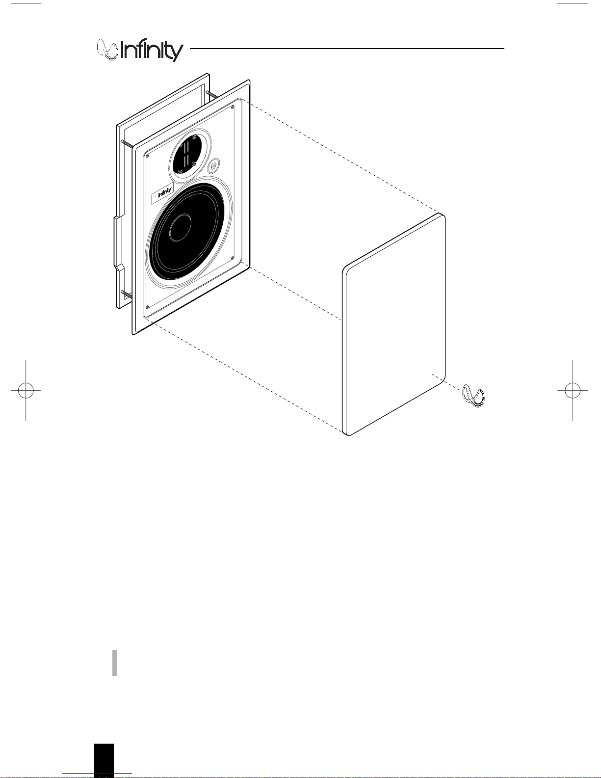
3. Verify that the package includes two sets of the following items
(one for each speaker), as shown in Figure 1 (on next page):
• Speaker/Frame Assembly
• Grille
• Paint Mask (not shown)
• Mounting Template (not shown)
• Infinity Logo (self-adhesive)
Page 3
2
Figure 1. Drawing shows assembly procedure (ERS 840 is shown).
Planning the Installation
When surveying potential installation sites for ERS Series
speakers, keep the following points in mind:
• Allow at least a two-inch clearance in all directions behind the
wallboard. The assembly is designed for easy horizontal or
vertical mounting between wall studs.
NOTE: Due to its size, the ERS 840 can only be mounted vertically.
It will not fit horizontally between standard 16" stud-centers.
• For the best stereo image, position the speakers not less than
seven to ten feet apart.
Speaker And
Frame Assembly
Grille
Infinity Logo
T
w
e
e
t
e
r
L
e
v
e
r
MaxMin
Page 4

ERS Series Installation/Owner’s Manual
3
• Examine the proposed path to run speaker cables to the
amplifier. Check for any obstacles (e.g., firebreaks) that may
hinder a cable run. If needed, consult a custom installation
specialist or building contractor to determine the best cable
runs in existing construction.
• Keep the speakers at least two to three feet from adjacent
walls. Remember, the proximity of your speakers to room
corners can drastically affect tonal balance in the bass and
lower middle frequencies.
• All speakers except the ERS 360 should be positioned so that
the tweeters are at ear level during normal listening sessions.
The ERS 360 is designed for ceiling mounting and should be
located in front of the listening area. The enclosed mounting
templates can be taped to the wall (or ceiling) to get a sense of
how the installation will look.
Required Tools and Parts
• Saber or jig saw
• Medium Phillips screwdriver
• Wire strippers
•Awl
• Two-conductor, polarity-coded, stranded speaker wire with
gauge determined by the following cable run lengths:
less than 6 feet – use minimum 18 gauge
6 to 30 feet – use minimum 16 gauge
30 to 50 feet – use minimum 14 gauge
• Wire snake
• Level
Page 5
4
Installing ERS Series Speakers
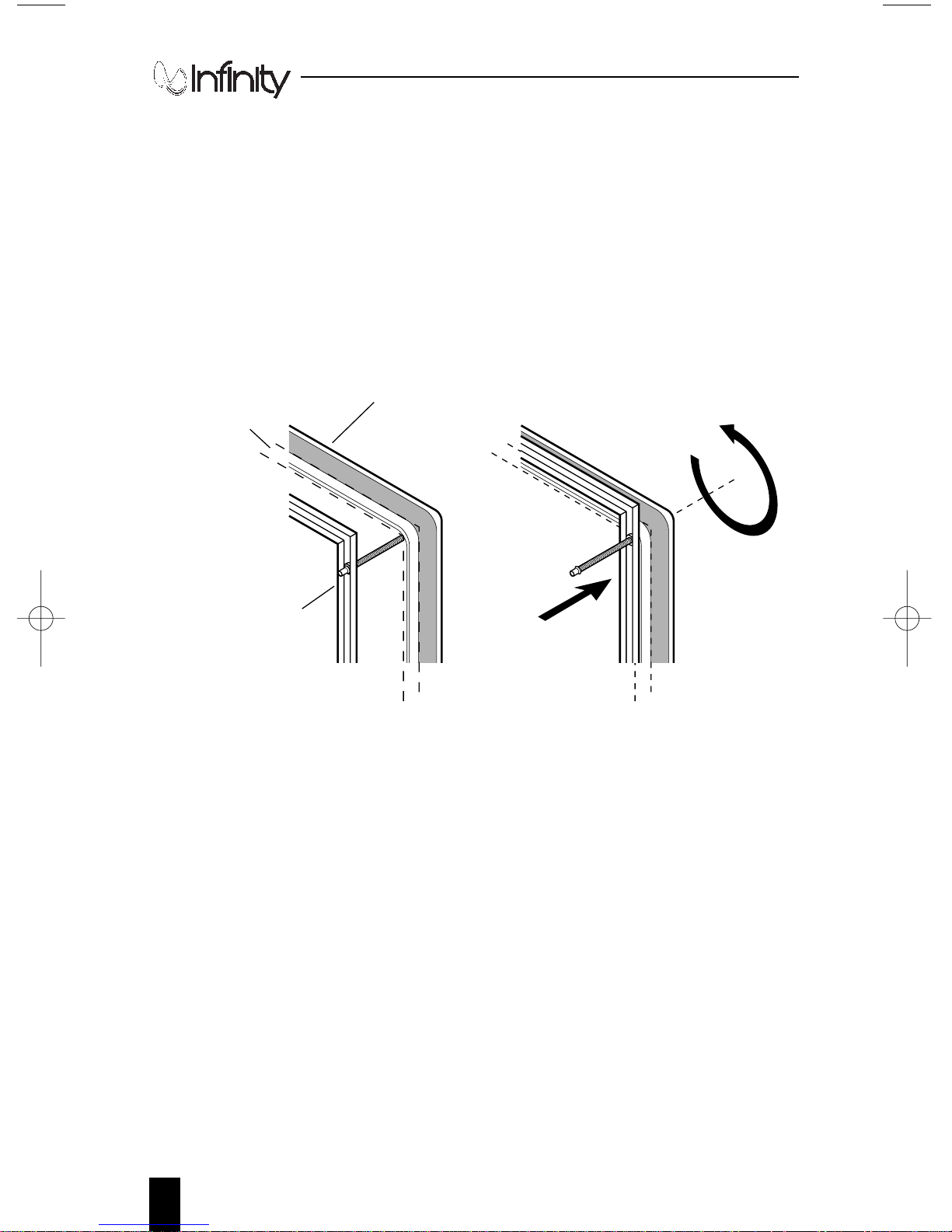
ERS Series Speakers use a built-in mounting system that
automatically engages when you start fastening the embedded
Phillips screws, as shown in Figure 2.
Turning each corner screw (clockwise) moves the mounting frame
to sandwich the back of the speaker baffle against the wallboard.
With this design, speaker installation is fast and easy.
Figure 2. The built-in mounting system used in the ERS 840, 640, 540, and
440 speakers is shown in the extended and closed positions. The ERS 360
has a circular frame, but operates the same way.
1. After selecting a site, use the enclosed Mounting Templates to
mark the boundary of each cutout and carefully cut it out. Use
a level to find a true horizontal (or vertical) position.
2. Make sure the amplifier is off before making connections.
Run the speaker cables from the amplifier to each speaker cavity.
Use the same lengths for left and right cable runs. Leave at least
a 12" service loop to facilitate speaker connection.
3. In order to improve low-frequency accuracy, loosely fill each
cutout cavity with dacron or fiberglass insulation material to
provide additional acoustic damping (optional).
Frame
Extended For
Mounting
Turn Screw
(1 of 4)
Speaker Baffle
(Rear View)
Frame Moves
Towards
Wallboard
Wallboard
Page 6
ERS Series Installation/Owner’s Manual
5
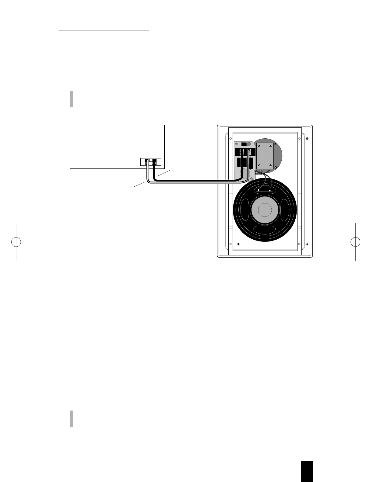
4. Strip the ends of the speaker wires about
3
⁄8". Twist the wire
strands together for terminal insertion. Connect the speaker
wires to the appropriate speaker terminals on each speaker, as
shown in Figure 3.
IMPORTANT: Make sure you observe the polarity codes (i.e.,
red is + and black is –).
Figure 3. Example of correct wiring connections used on the ERS 840.
Other models are wired similarly.
5. Before mounting the speakers, make sure the attached
mounting frame is in the extended position (see Figure 2 on
page 4). For each speaker, insert the bottom of the mounting
frame (and cable) into its respective cavity. Insert the top of the
mounting frame into the opening and slide the baffle up to fit
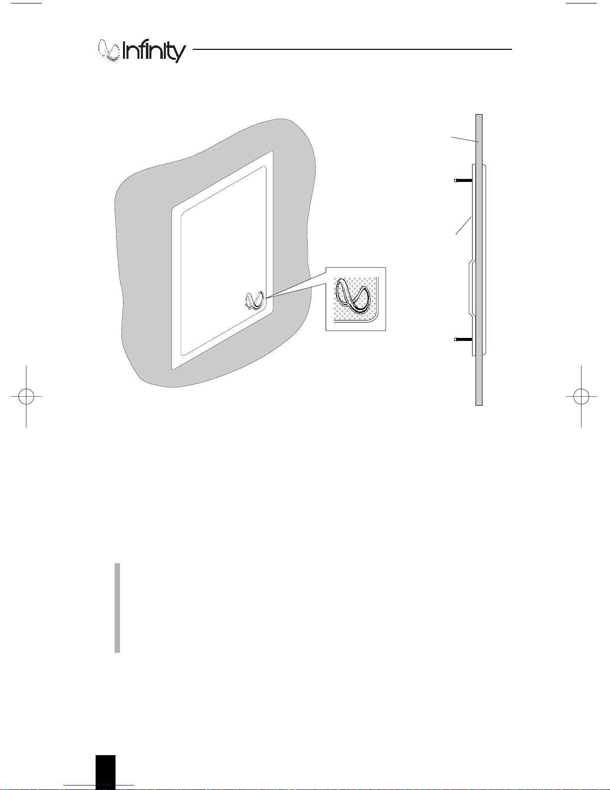
the cutout. Equally tighten each of the four Phillips screws
(already inserted) to sandwich the mounting frame against the
wallboard, as shown in Figure 4 on page 6.
CAUTION: DO NOT OVERTIGHTEN SCREWS! Doing so may
damage the assembly.
+
use wire with
ridge on jacket
or gold wire
–
AMPLIFIER
(Rear View)
ERS 840 (Rear View)
use wire with no
ridge on jacket
or silver wire
+
–
Page 7
6
Installing ERS Series Speakers (cont’d)
Figure 4. The mounting frame sandwiches the speaker baffle to the
wallboard. The ERS 840 is shown here.
6. (Optional) Place paint masks over the speakers before painting
the speaker’s frame. Paint the grilles before inserting them onto
the frames. Be careful not to get paint on the speakers or let it
clog the holes in the grilles. Let the paint dry thoroughly before
performing the next step.
NOTE: If you want to cover the grille with an acousticallytransparent cloth instead of paint, apply a small amount of grille
cloth adhesive around the inside edges of the grille and wrap the
cloth smoothly around it. After drying, trim any excess cloth from the
grille. Consult your Authorized Infinity ERS Series dealer for
additional help with this option.
Side View
Wallboard
ERS 840 installed in wall
Frame
Presses
Wallboard
Place Infinity Logo (self-adhesive)
in lower right corner of grille
Page 8

ERS Series Installation/Owner’s Manual
7
Adjusting ERS Series Speakers
1. If you purchased an ERS 840 or 640, you will need to adjust the
built-in tweeter level control (if not, skip to Step 2). Start with each
control at the 12:00 position, and listen to a wide variety of program
material. Adjust each control until you hear the high frequencies
blend well with the upper midrange frequencies. Generally, once
set, each control should remain at the chosen settings unless there
is a significant change in the room environment.
2. When finished, gently insert the grilles into the slots on the
speaker frames. Place an Infinity Logo (self-adhesive) on each
grille (see Figure 4 on page 6). For the ERS 360, place the logo
along the grille’s circular edge.
NOTE: Rooms with heavy drapes, thick carpets and heavily-padded
furniture will require more output from the tweeters than rooms with
a wide expanse of glass or mirrors, hard floors, or smooth furniture.
Associated Components
The choice of associated components in your system is critical and
should be made with great care. Here are several suggestions:
• Use a high-powered amplifier (see page 9 for minimum/maximum
power ratings for ERS models). Higher power results in not only
cleaner, more open sound, but insures that the speaker will not be
harmed by an overdriven system that is generating distortion.
• Never operate your system with the bass, treble and loudness
controls set to full boost. This will place undue strain on the
speakers, as well as the amplifier.
• Always turn down the volume control when changing a CD,
record or tape, or switching to AM or FM operation.
Excessively loud transients (clicks or popping sounds) can
damage the speakers.
• Whenever changing cables, pulling plugs, etc., always turn off
all equipment to prevent transients from entering the
speakers. It is always worthwhile discussing proper speaker
connection and component selection with your dealer prior to
setting up your system.
Page 9

8
A Word About Tone Controls...
The tone controls on your electronic components (e.g., preamplifier, receiver, etc.) should be used with the utmost
discretion. Excessive boost can create severe power demands on
your power amplifier. Maximum bass boost can create a demand
for literally hundreds of watts in the bass region, whereas in the
“flat” position (or with the tone controls switched out of the
system), the average listening level may be impressively and
realistically loud at less than 10 watts. The remaining power
capacity required is on reserve for power peaks on sharp
transients and crescendos.
Nominal impedance refers to how much current is required, on
the average, from an amplifier for a given voltage at its output
terminals. Impedance is not an indication of quality or accuracy
in a loudspeaker.
Solid state amplifiers, properly designed and constructed, will
generally deliver more power at 4 ohms. Ask your dealer about
the actual power and reliability of your amplifier or receiver at
this impedance.
Understanding “Min/Max” Power Ratings
If you intend to use your speakers for background music, or at
moderate levels in a small room, an amplifier or receiver with the
recommended minimum power rating can be used. But it is
important to be aware of potential damage to tweeters that exists
when a low-powered amplifier or receiver is played at volumes
beyond its normal limits.
At extremely loud listening levels, all amplifiers will “clip”
(distort) the peak of musical signals. When this happens, the
resulting harsh distortion may contain a considerable amount of
supersonic energy which is routed to the tweeters, potentially
damaging them.
The ERS 840 employs an internal protection device to help prevent
its tweeter from being damaged in the case of overload conditions.
Page 10

ERS Series Installation/Owner’s Manual
9
If the sound from the tweeters cuts in and out, especially near your
amplifier’s power limits, turn the volume down.
The recommended amplifier power ratings to drive Infinity ERS
speakers are:
ERS 840 – 15 to 100 watts (rms) per channel
ERS 640 – 10 to 75 watts (rms) per channel
ERS 540 – 5 to 50 watts (rms) per channel
ERS 440 – 5 to 25 watts (rms) per channel
ERS 360 – 5 to 50 watts (rms) per channel
In Case Of Trouble
Contact your Infinity dealer for the name of the authorized
Infinity service center nearest you.
If there is no facility near you, contact the Infinity Customer
Service Department at (818) 407-0228, by FAX at (818) 709-9486,
or write to:
Infinity Systems, Inc.
Customer Service Department
20630 Nordhoff Street
Chatsworth, CA 91311 (U.S.A.).
NOTE: Do not ship your speakers for service without obtaining
prior approval (“return authorization”). Make sure you enclose
a copy of your original bill of sale. For complete warranty
details, see page 10.
Page 11

10
LIMITED WARRANTY
Who is protected by the warranty?
Your Infinity warranty protects the original retail purchaser and all
subsequent owners for a period of five (5) years (parts and labor) from any
failure as a result of an original manufacturing defect so long as: (1) your
Infinity loudspeakers were purchased within the fifty United States or by
military personnel from an authorized military outlet and (2) the original
dated bill of sale is presented whenever service is required during the
warranty period. This warranty does not apply to products purchased
elsewhere; other purchasers should contact their local Infinity distributor for
warranty information.
What does the Infinity warranty cover?
Except as specified below, this warranty covers all defects in original materials
and workmanship. The following are not covered: damage caused by accident,
misuse, abuse, neglect, product modification; damage occurring during shipment,
damage caused by failure to follow instructions in the owner’s manual, including
failure to perform recommended periodic or routine maintenance; damage
resulting from repairs by someone not authorized by Infinity; claims based upon
any misrepresentations by the sellers; and any Infinity product on which the
serial number has been altered, defaced or removed.
Who pays for what?
During the period of this warranty, subject to the above conditions, Infinity
will pay all of the labor and material expenses to repair a warrantable defect.
How can warranty service be obtained?
In the event that your loudspeaker(s) should require service, you should first
contact the Infinity dealer from whom the product was purchased or, if this is
not practical, contact Customer Service in writing at:
Infinity Systems, Inc., 20630 Nordhoff Street, Chatsworth, CA 91311 USA
or by calling us at (818) 407-0228 (FAX: 818-709-9486)
We may direct you to an authorized service center for Infinity product or ask you
to send them to us for repair. In either case you will have to present your original
dated bill of sale to establish warranty coverage. Do not send your speaker(s) to
us without prior authorization from our Customer Service department.
You are responsible for transporting your product to either Infinity or an
authorized service center and for payment of all shipping charges; however,
Infinity will pay the return shipping charges (in the event you return the
product to us) if the repairs are covered by the warranty. If you experience
difficulty in transporting your product or are in need of packing materials,
please advise us and we may be able to suggest alternative procedures and/or
adequate packaging materials.
Page 12

ERS Series Installation/Owner’s Manual
11
LIMITATION OF IMPLIED WARRANTIES: All implied warranties,
including fitness for a particular purpose and merchantability are limited in
duration to the length of the warranty period for your product.
LIMITATION OF INCIDENTAL OR CONSEQUENTIAL DAMAGES:
Infinity is not responsible for an incidental or consequential damage of any
kind. Our liability is limited to the repair or replacement, at our option, of a
defective product.
Some states do not allow limitations on how long an implied warranty lasts and/or
do not allow the exclusion of incidental or consequential damages, so the above
limitations or exclusions may not apply to you. This warranty gives you specific
legal rights and you may also have other rights which vary from state to state.
NOTE: In the event that there is a difference between this warranty and
the provisions in any advertisements, product brochure or packaging
cartons, the terms of this warranty will prevail.
Infinity constantly strives to update and improve existing products, as well as
create new ones. Therefore the specifications and construction details in this
and related Infinity publications are subject to change without notice.
©1994 Infinity Systems, Inc., 20630 Nordhoff Street, Chatsworth, CA 91311 USA
Page 13

®
Infinity Systems, Inc.
20630 Nordhoff Street, Chatsworth, CA 91311 USA
(
818)407-0228
•
FAX (818)709-9486
P/N.930...6850APrinted in Taiwan
 Loading...