

Page 1
CorrectIncorrect
TOOLS FOR ASSEMBLY ARE INCLUDED
Your new bicycle was assembled and tuned in the factory and then partially disassembled for shipping. The following instructions will enable you to
prepare your bicycle for years of enjoyable cycling. For more details on inspection, lubrication, maintenance and adjustment of any area, please refer
to the relevant sections in your owner’s manual. Should you require replacement parts or have any questions pertaining to the assembly of your
bicycle, call our service line direct at:
Boss.three 700c Men’s Hybrid Bicycle
Here is a picture of your assembled
bicycle.
Be sure to double check that all
quick release and bolts are secure
before riding.
Always wear a helmet.
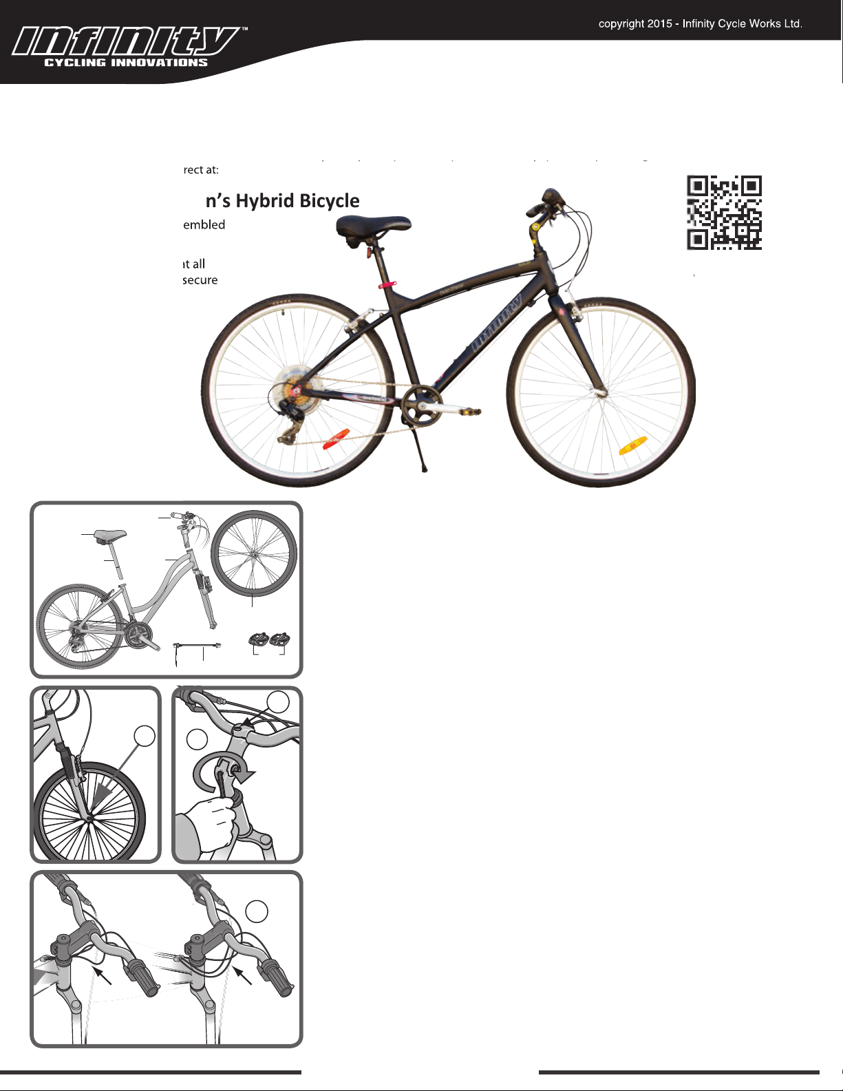
Handlebar assembly
Seat
Seat post
Frame
A
Quick Release
B
Front wheel
Pedals
ASSEMBLY
VIDEO LINK
GETTING STARTED
Open the carton from the top and carfully remove the bicycle. Now remove all ties and
protective wrapping making note of parts as you go along. Do not discard packing
material until assembly is complete to ensure no required parts are accidentally
discarded.
HANDLEBAR ASSEMBLY
C
Remove all protective packaging from the handlebar assembly, if not already done.
Turn the fork of the bicycle to face forward. (Note that "forward" means that the wheel
mounting slots are in the furthest forward position, so the wheel axle will be in front of
the fork when assembled.) Look for removable decal and information card on the fork
showing the proper direction.
If your model comes equipped with gears and/or handbrakes, you will need to be sure
that the brake cables and shift cables are properly routed. Position the handlebar
assembly as if you were going to install it and take a look at the cables. They should
run in a smooth arc from the shifter or brake lever to the front brakes or cable stop on
the frame. If they are twisted or kinked, the shifting and braking will not work. Rotate
the handlebars around until the cables are taking the smoothest route.
(A)
(D)
D
Loosen the center bolt
steer tube. Lower the stem until the mark that says "minimum insertion" is no longer
visible. Tighten the stem center bolt so that the handlebar assembly is in line with the
fork. If needed, you can recheck this after the front wheel is installed and re-adjust.
Check handlebar stem clamp bolt
handlebar cannot move. The angle of the handlebar can be adjusted. To adjust: loosen
all of the handlebar stem clamping bolts and rotate the handlebar to the desired
angle. Be sure that the handlebar stays centered in the stem. Re-tighten the bolts a
little at a time
Repeat tightening each bolt a little bit until handlebar is secure.
www.infinitycycleworks.com
, being sure that the gap between the stem cap and stem stays even.
(B) enough so that the wedge and stem can slide into the fork
(C) to be sure they are properly tightened and
Page 2
Close
HANDLEBAR ASSEMBLY
If
to o
in
front wheel. Try turning the handlebar. If you can turn it without turning
the front wheel, the stem is too loose. Re-align the handlebar with the
fron
F
E
G
E
G
B
F
H
I
FRONT WHEEL
VIDEO: h
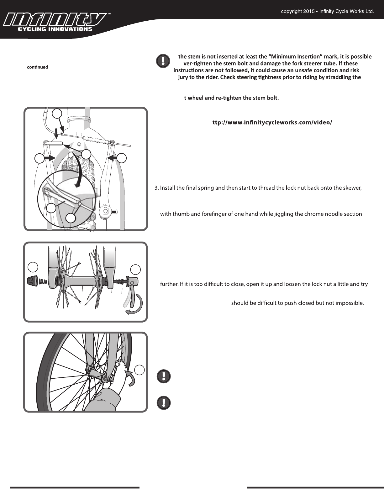
1. Locate the quick release skewer attached to the spokes of your front wheel (see
image GETTING STARTED). Some tire tread patterns have a direction, so compare
the front and rear tires of the bicycle so that both tread patterns face the same way.
2. Unscrew the lock nut from the quick release skewer
and slide the skewer through the hollow axle on the front wheel so that the handle
is on the left side of the bicycle (the side opposite the chain).
but do not tighten too far.
4. Release the front brakes by pinching the upper area of the brake arms together
(F) of the cable housing free from the assembly (G) with the other hand. Brakes
will be spread wide to accommodate the wheel.
5. Slide the wheel into the fork wheel slots and be sure that the wheel is centered.
6. Inspect the handle of the skewer
position. Move the handle so that it is in the "open" position. Start to hand tighten
the lock nut (H) until you begin to feel some resistance with the fork.
7. Try to close the handle. If it closes to easily, open it up and tighten the lock nut
again.
(I), note that there is an "open" and "closed"
(H), remove the outer spring
(E)
8. The quick release handle
Practice opening and closing the handle until you feel comfortable. DO NOT
attempt to tighten skewer by turning the handle; the handle is for closing, the lock
nut is for adjusting the tension.
9·. Reverse step 4 to re-attach the brakes.
Once completed, go back and check that the handlebars are perpendicular to the
front wheel, if needed return to the handlebar assembly section and re-adjust.
I
All quick release levers should be inspected before every ride to be sure
they are fully closesd and secure. Failure to properly close a quick release
lever can cause loss of control of the bicycl resulting in injury or death.
Make sure the wheel is properly seated and the quick release is properly
closed.
(I)
www.infinitycycleworks.com
Page 3
NUTTED FRONT WHEEL
(for models without quick release front wheel)
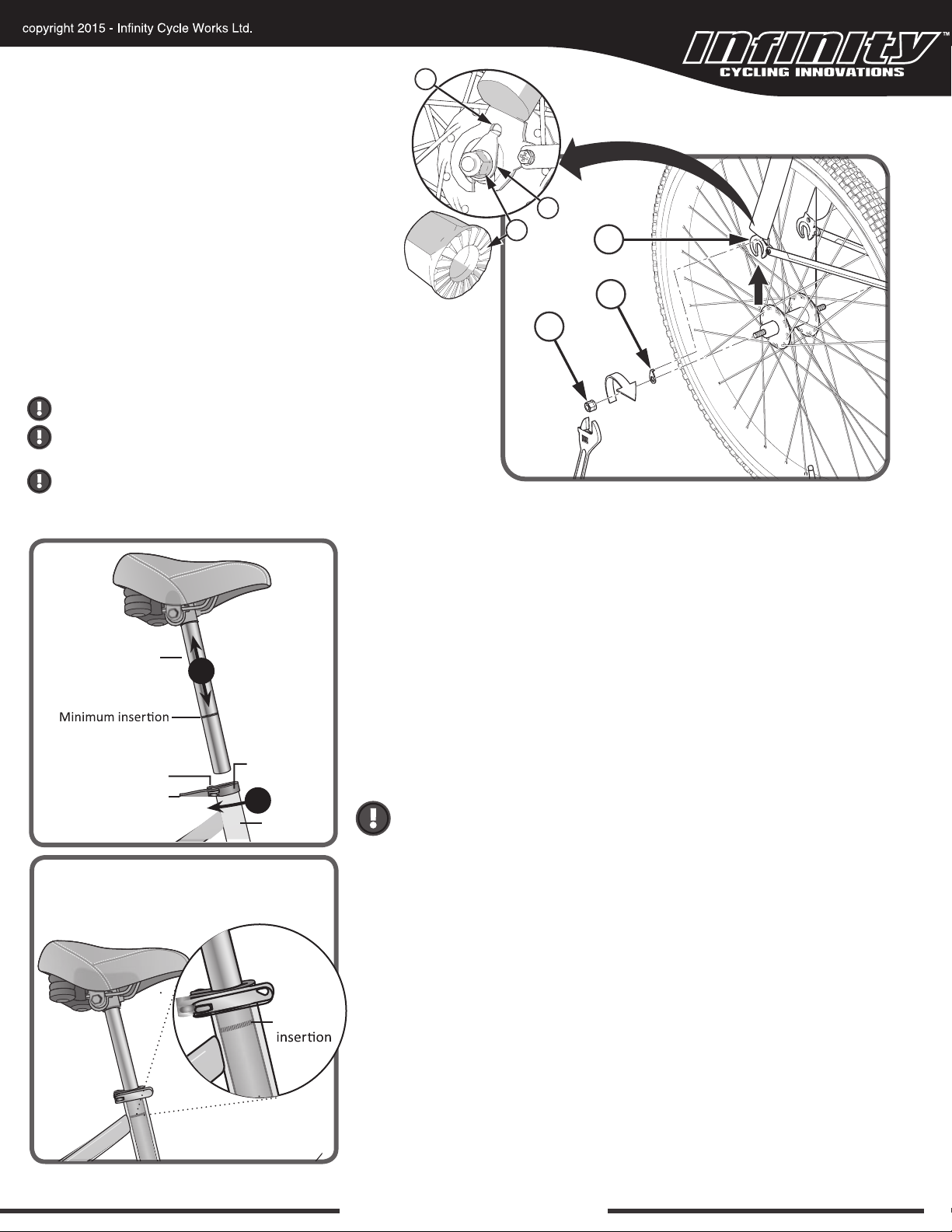
1. If the Axle Nuts (J) are already attached to the front
wheel axle, begin by removing them with an open end
wrench or adjustable wrench.
2. Set the wheel into the front fork
3. Install wheel retainer washers
are in the fork
4. Attach the front wheel with the Axle Nuts
5. Tighten Axle Nuts with 15mm wrench provided.
NOTE: Ensure wheel spins freely without contacting
WARNING: Do not use Nuts (G) without serrations to attach the front wheel.
WARNING: Put the wheel in the center of the fork and tighten
both nuts to the recommended torque.
WARNING: Failure to obey these steps can allow the front wheel to loosen
while riding. This can cause injury to the rider or to others.
(M) tab holes.
(K)
(L) making sure the tabs
(J).
M
L
J
K
L
J
Seat post
marks on the seat post
Adjustment nut
Quick-release lever
O
Quick-release
seat clamp
N
Seat tube
SADDLE ASSEMBLY
The saddle assembly should be adjusted with the saddle centered on the rails and
level. Insert the saddle assembly into the frame.
Adjust seat to desired height
saddle may not turn left or right, or move up or down. If it moves after locking the
quick release lever, open it and tighten the adjusting nut further, then close the quick
release lever again.
Be sure that the seat post is inserted far enough into the frame so that the "minimum
insertion" mark on the seat post is no longer visible. Riding the bicycle with the seat
post above this line is dangerous and can cause serious injury, damage to the bicycle
and/or create an unstable riding position causing an accident.
Before each ride check to be sure the seat post is inserted so that the
minimum insertion mark cannot be seen. The quick release mechanism is
tightened securely to prevent accidental slippage.
(O) and tighten the quick release clamp (N) so that the
Minimum
marks
3
www.infinitycycleworks.com
Page 4
PEDALS AND CRANKS
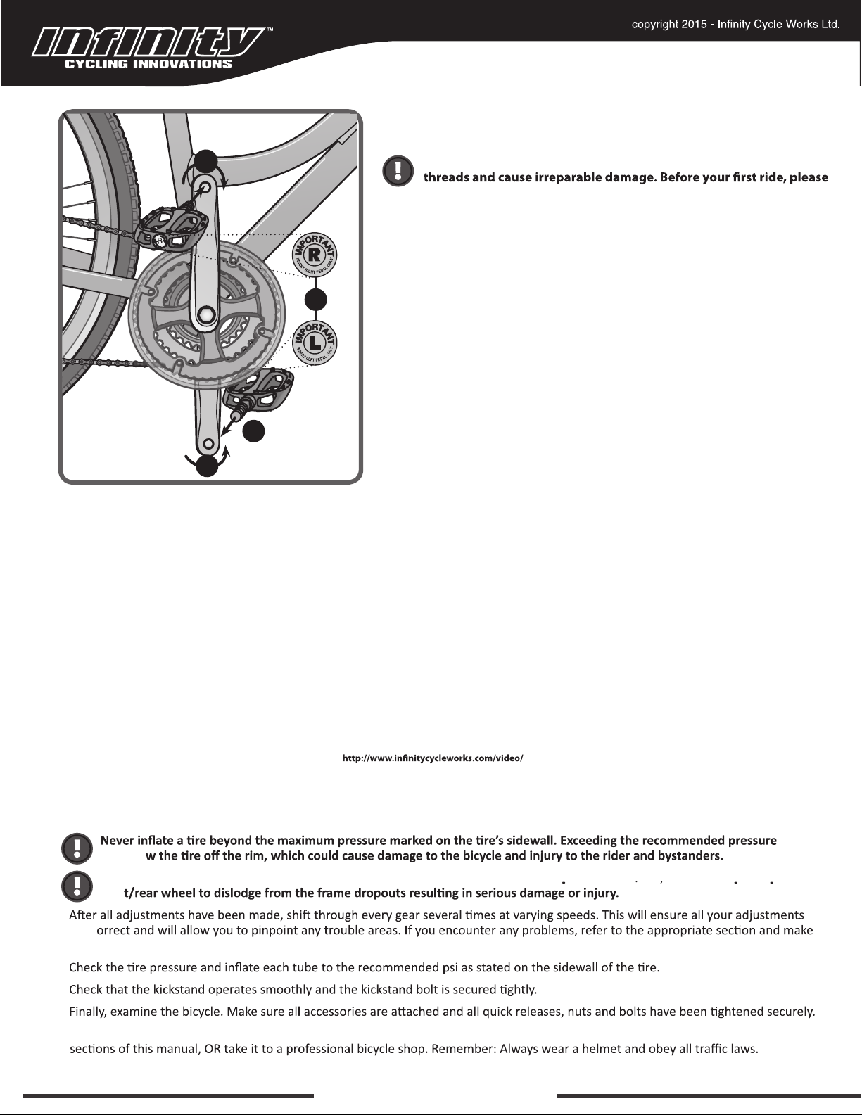
The left pedal turns
counter-clockwise
and the right pedal
turns clockwise.
2
Look for the letters (1) “R” for right, and “L” for left, stamped on each pedal
spindle. Start each pedal spindle
that the right hand pedal attached to the chainwheel side crank arm with a
right-hand (clockwise) (2) thread. The left pedal attached to the other crank arm
and has a left-hand (counter-clockwise thread)
1
wrench provided. It is very important that you check the crank set for correct
adjustment and tightness before riding your bicycle.
Attachment of an incorrect pedal into a crank arm can strip pedal
check to ensure your pedals are attached securely and correctly.
(4) by hand to avoid stripping the threads. (Note
(3). Tighten with the 15mm pedal
4
3
SERVICE & TECHNICAL SUPPORT
TOLL FREE 1.855.521.1127
Monday - Friday 8:00 a.m. to 4:00 p.m. Pacific Time
FINAL CHECK
may blo
Tighten both front/rear wheel axle nuts or the quick release mechanism securely. Failure to do this may cause the
fron
•
are c
any necessary adjustments.
•
•
•
• Correct maintenance of your bicycle will ensure many years of happy riding. Service your bicycle regularly by referring to the relevant
www.infinitycycleworks.com
 Loading...