

Page 1
Instruction for user,
Installation &
Servicing
780HD
Keep this booklet for service log and future reference
IMPORTANT
This appliance is guaranteed for 12 months subject to conditions. The 5 year extended parts
warranty will only be valid if the annual service recommended in this manual has been
completed and appliance has been registered online.
Video guides found at http://www.charltonandjenrick.co.uk/infinity-set-up-guides/
Page 2

P a g e | 1
LT7185 Iss 2 (06/18)
Contents
EXTENDED PARTS WARRANTY ..................................................... 1
Benchmark Scheme ................................................................... 2
Introduction ............................................................................. 3
Consumer Protection Information .......................................... 3
Lighting the Appliance & General Operation Of Control .... 5
Handset set up video .............................................................. 5
Auto (Thermostatic) Control ................................................... 7
Menu features.......................................................................... 8
Changing The Handset Batteries. .......................................... 8
Cleaning the 780 HD Appliance ............................................ 9
Fuel Bed Layout ..................................................................... 10
Birch Fuel bed .................................................................... 10
Walnut fuel bed .................................................................. 17
Technical Specification ........................................................ 24
Siting the Appliance ............................................................. 25
Installation of the Appliance ................................................ 33
Commissioning the Appliance ............................................ 42
Annual Service Requirement. .............................................. 46
Fault Finding Charts ............................................................... 48
Wiring Diagram ...................................................................... 51
Maintenance ......................................................................... 52
Short Spares List ..................................................................... 56
GAS FIRE COMMISSIONING CHECKLIST ................................ 61
SERVICE RECORD ...................................................................... 62
EXTENDED PARTS
WARRANTY
In order to validate your extended parts
warranty please read the Benchmark
Scheme on the opposite page and
ensure your installer has filled in the appropriate checklist.
This in no way reduces your statutory rights
Your warranty commences from the date of purchase and you
must retain your receipt or invoice as proof of a purchase date.
THIS EXTENDED WARRANTY SPECIFICALLY EXCLUDES GLASS AND
SOFT REFRACTORY COMPONENTS, THE BULB AND ANY BATTERIES.
Terms and Conditions
1. The appliance must be installed by a GAS SAFE
registered person.
2. The appliance must be used in accordance with the
user’s instructions.
3. The appliance must be serviced annually by a GAS
SAFE registered person.
4. The benchmark and service log must be correctly filled
out and the record of annual services must be up to
date and supported by receipts in each case.
5. This warranty is not transferable and relates to the
original installation only.
6. The appliance has not been subjected to misuse or
accident or been modified or repaired by any person
other than the authorized employee or authorized
representative of Charlton and Jenrick Ltd.
7. The registration form must be returned within 1 month of
purchase.
8. Please complete the benchmark commissioning check
list at the rear of this document
Technical Help Desk 01952 200 444
For gas emergency call Transco: 0800 111 999
Page 3

P a g e | 2
LT7185 Iss 2 (06/18)
Benchmark Scheme
Charlton and Jenrick Ltd is a licensed member of the Benchmark Scheme which aims to
improve the standards of installation and commissioning of domestic heating and hot
water systems in the UK and to encourage regular servicing to optimise safety, efficiency
and performance. Benchmark is managed and promoted by the Heating and Hotwater
Industry Council. For more information and the full code of practice please visit
www.centralheating.co.uk
Please ensure that the installer has fully completed the Benchmark Checklist on the inside
back pages of the installation instructions supplied with the product and that you have
signed it to say that you have received a full and clear explanation of its operation. The
installer is legally required to complete a commissioning checklist as a means of
complying with the appropriate Building Regulations (England and Wales).
All installations must be notified to Local Area Building Control either directly or through a
Competent Persons Scheme. A Building Regulations Compliance Certificate will then be
issued to the customer who should, on receipt, write the Notification Number on the
Benchmark Checklist.
This product should be serviced regularly to optimize its safety, efficiency and
performance. The service engineer should complete the relevant Service Record on the
Benchmark Checklist after each service.
The Benchmark Checklist will be required in the event of any warranty.
It is a requirement that the gas fire is installed and commissioned to the manufacturer’s
instructions and the data fields on the commissioning checklist completed in full.
To instigate the guarantee, the gas fire needs to be registered with the manufacturer
within one month of the installation.
To maintain the guarantee, it is essential that the gas fire is serviced annually by a Gas
Safe registered engineer. The service details should be recorded on the Benchmark
Service Interval Record and left with the householder.
Page 4

P a g e | 3
LT7185 Iss 2 (06/18)
780 HD USERS INSTRUCTIONS
Introduction
The 780 HD has been designed and tested to the requirements of EN 613 and is suitable for use in
Great Britain & Republic of Ireland.
780 HD incorporates a single gas valve which selects ignition pilot, with variable setting between
low and high setting and is operated via remote control hand device or optional smart app
device. This system is powered by mains electricity via pre-wired transformer plus supply cord.
Alternative power supply is available for users during mains interruptions.
The 780 HD incorporates a safety device in form of an Oxygen Depletion System, which
constantly monitors the oxygen in the room and will cause the fire to switch off if the oxygen
level reduces, for instance due to insufficient ventilation or a blocked flue.
Consumer Protection Information
As manufacturers and suppliers of heating products, we take every care to ensure that the
design and construction has to meet the general safety requirements when properly used and
installed. To this end, our products are thoroughly tested and examined before despatch.
Any alteration that is not approved by the manufacturer could invalidate the approval of the
appliances, operation of the warranty and could affect your statutory rights.
This appliance could contain some materials that could be interpreted as being injurious to
health. It is the users / installers responsibility to wear protective clothing when handling the
following materials. Artificial fuel, mineral wool, insulation material, refractory/ceramic fibres and
glass yarn. May be harmful if inhaled, may be irritating to skin, eye, nose and throat.
When disposing refractory / ceramic materials to keep dust to a minimum these materials should
be securely wrapped in polythene and clearly labelled “RCF waste”. These materials are not
classified as hazardous waste and should be disposed of at a site licensed for disposal of
industrial waste.
Page 5

P a g e | 4
LT7185 Iss 2 (06/18)
780 HD USERS INSTRUCTIONS
Important Information
The appliance is for use on Natural Gas (G20 @ 20mbar) or LPG (G31 @ 37mbar).
The Chimney or flue (unless new or previously used with a gas appliance) shall be swept before
installation if been used for solid fuel.
In Great Britain, the appliance must be installed by a competent person whose name appears
on the gas safe register. All Gas Safe engineers should possess an ID carrying the logo below.
In IE (Ireland), the appliance must be installed by a competent person and
installed in accordance with the current edition I.S 813 Domestic Installation.
The glass front of this appliance acts as a dress guard, conforming to BS 1945 (1997) however a
fireguard to BS6539 (1997) must be used to protect young children, the elderly or infirm.
The Appliance must not be used with the glass safety screen removed or if it is damaged or
cracked.
During initial “burn off”, an odour may be evident during the first few hours of use. This is due to
the surface coating on the metal work “burning off”. The odour produced is harmless and will
disappear after a short period of time.
During the normal operation of the fire some black staining may appear on some parts of the
fuel bed. This is quite normal. However, if excessive black staining occurs it may be due to the
fuel bed shapes laid incorrectly. This should be checked prior to contacting a service engineer.
Care must be taken to prevent any damage being caused to surrounding soft furnishing or
decoration. Many embossed vinyl coverings may become discoloured if placed too close to the
appliance. It is suggested that a sample of the proposed wall covering should be placed above
the appliance at its hottest point first. The appliance should then be run on high rate over a
couple of days
It is advised that this appliance is serviced annually as recommended by Gas Safe. This is more
likely to provide trouble-free operation and is a requirement of the extended warranty.
In GB (Great Britain) the fire does not normally require purpose built ventilation, but if for any
special reason purpose built ventilation is provided it should be checked periodically to ensure
freedom from obstructions.
In IE (Ireland) permanent ventilation must comply with the current edition of IS813.
780 HD USERS INSTRUCTIONS
Page 6
P a g e | 5
LT7185 Iss 2 (06/18)
Lighting the Appliance & General Operation Of Control
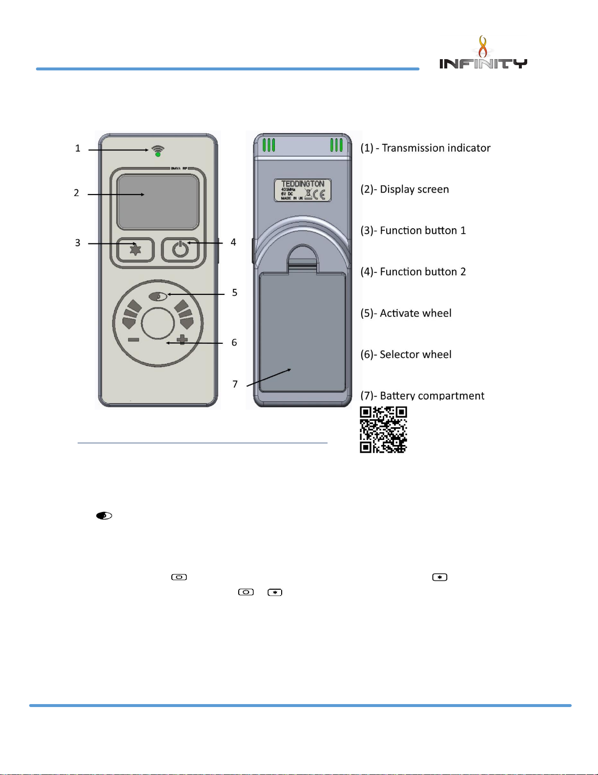
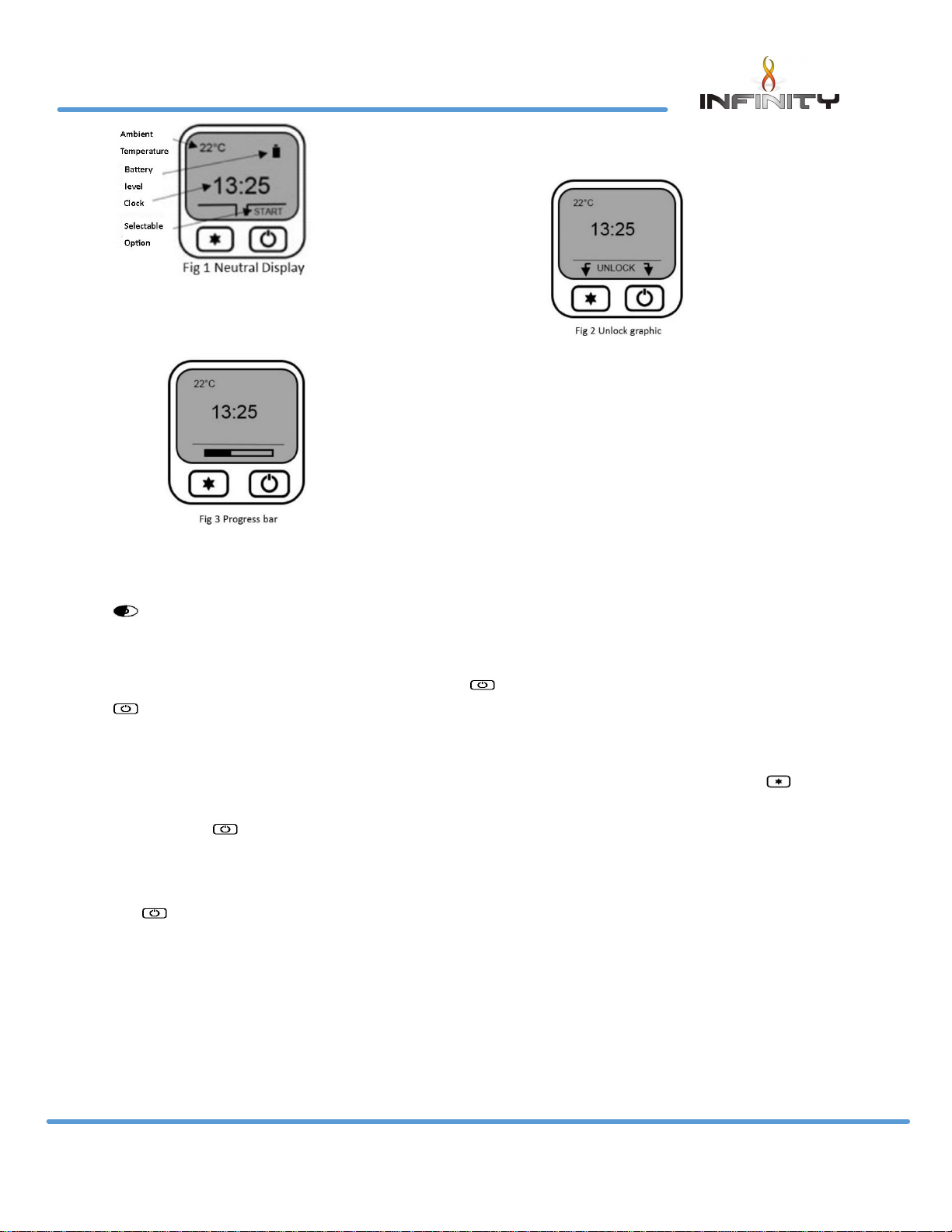
Display overview
Press to awaken the handset from its dormant sleep mode at any time. Fig 1 shows the
display neutral, ready to turn on.
Turn on (start up).
Pressing and holding displays an “UNLOCK” graphic Fig 2 prompting the button to be
pressed simultaneously. Whilst both & are pressed a progress bar Fig 3 will complete. If
either button is released before the progress bar has completed the operation will cancel. Once
the progress bar has completed the handset will display the status of the fire (priming – ignition –
pilot – main burner) finishing at the fire “on” display screen Fig 4.
780 HD USERS INSTRUCTIONS
Handset set up video
http://www.charltonandjenrick.co.uk/handsetguide/
Page 7
P a g e | 6
LT7185 Iss 2 (06/18)
Flame height adjustment
Once the fire has been started the flame height can be decreased
by moving your finger clock wise or decreased moving your finger anti-clock wise using the
selector wheel. Once the desired flame level is set, remove your finger from the selector wheel
to transmit your selection to the receiver. Six flame levels and a pilot setting are selectable. Press
whilst the display is active to display the current flame level.
Turn off (shut down)
To turn the appliance off, press and hold down until the progress bar has completed. If the
is released before the progress bar has completed the operation will cancel.
Mode select
With the fire running on manual operation you can access three further “modes”. Press for
“mode”. Use the selection wheel to cycle through the three options, “Auto”, “Sleep” and
“Light”. Press to select “Auto” or “Sleep”
Sleep:- Use the selector wheel to choose from the available time range of 5 minutes to 1 hour 30
minutes. Once the desired countdown time has expired the appliance will turn off. By pressing
the button during the countdown will cancel the countdown timer if required.
Note: The handset contains a sensitive temperature measurement device. To achieve the best
thermostatic efficiency do not place the handset near the heat source, avoid covering, direct sunlight or
near a draft or open window etc. Place the handset at a midpoint in the room or area being heated. Allow
5-10 minutes for the handset to stabilize if subjected to extremes of temperature.
780 HD USERS INSTRUCTIONS
Page 8
P a g e | 7
LT7185 Iss 2 (06/18)
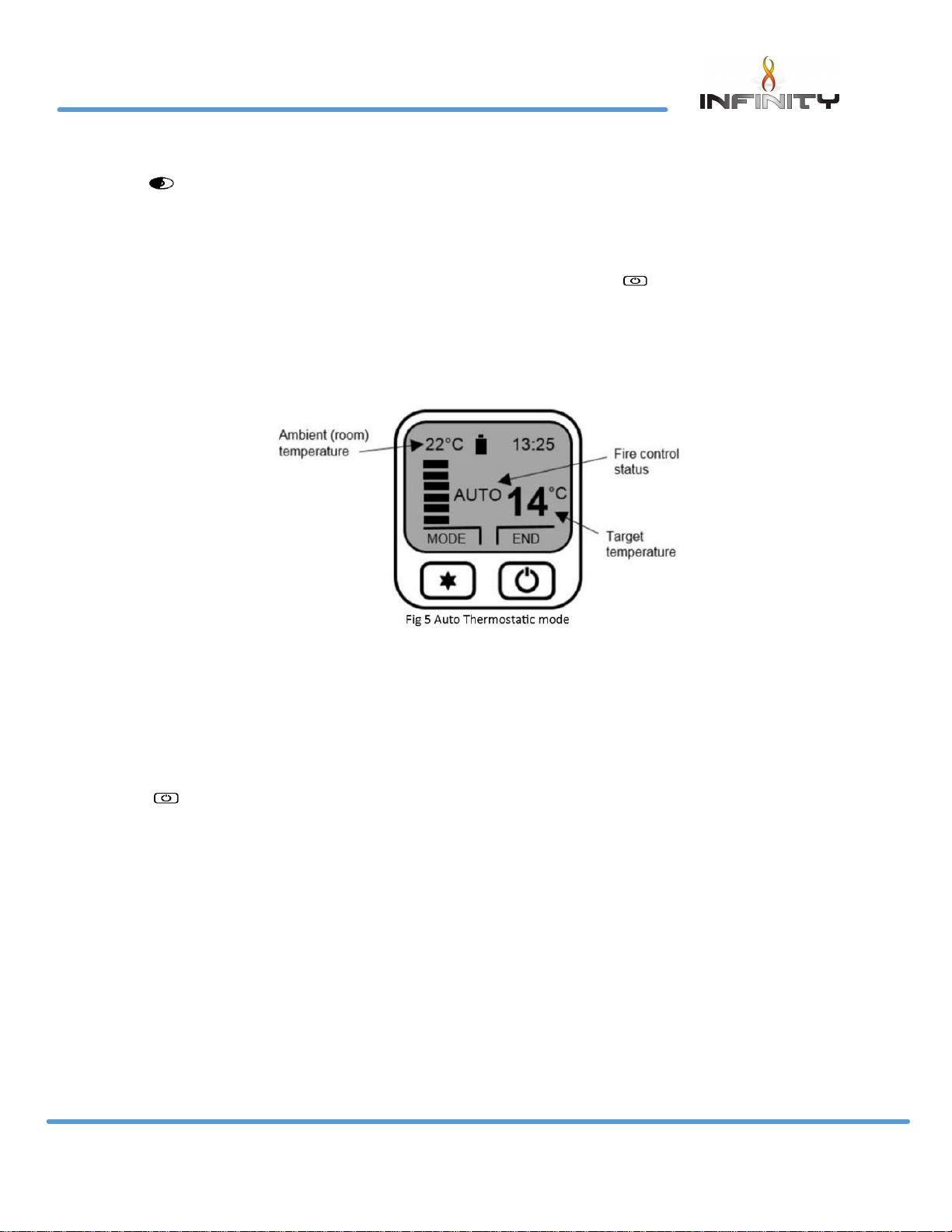
Auto (Thermostatic) Control
Press to awaken the handset from its dormant sleep mode at any time.
Selecting auto control
The “auto” function can only be selected once the appliances has been started and initiated
into “manual” mode. Once in manual mode, press and release the button to enter the
“mode” options. Auto is the first option, press to enter auto mode.
Adjusting target temperature
Use the selection wheel to increase or decrease the temperature to the desired level, release
your finger from the wheel to transmit the target temperature (See Fig 5) to the receiver. The
“auto” function will now modulate the flame height to achieve your target temperature. The
selectable temperature range is 1 degree C to 29 degree C.
Cancelling auto function
Press to “end” and cancel the “auto” control. The handset will return to manual control.
780 HD USERS INSTRUCTIONS
Page 9
P a g e | 8
LT7185 Iss 2 (06/18)
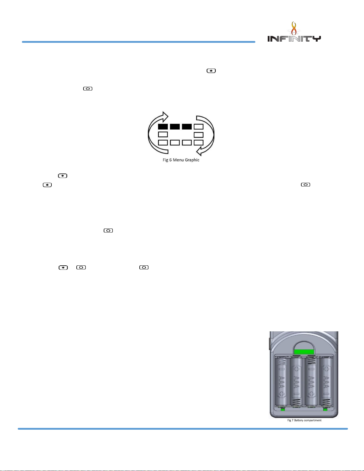
Menu features
The menu can be accessed by pressing and holding the button (approx. 5 seconds) until the
menu graphic completes (see fig 6). Use the selector wheel to highlight one of the available
options. Press to enter the required option.
Set clock
The handset clock has a dedicated 24 hour display. Use the selector wheel to firstly set the hours.
Press to change to minutes select. Use the selector wheel to change the minutes. Press the
button to alternate hours and minutes to make any other alterations. Finally, press the
button to save the clock setting.
Display
Temperature display units-use selector wheel to select either Celsius (degree C) or Fahrenheit
(degree F). Press the button to save selection.
Gas fire (pair code)
The device screen displays the current operating channel of the handset. To delete the channel
press & simultaneously or to return to the menu option.
Reset
To restore the handset back to its original factory setting select “reset” from the menu options.
Press - & - simultaneously to complete the reset command – to return to the menu options.
Changing The Handset Batteries.
The handset operates from four AAA 1.5V batteries. New alkaline batteries
are recommended. Do not mix new and old batteries. When inserting the
batteries, observe and position batteries according to the battery
compartment graphics (see Fig 7). When the batteries are inserted the
handset will attempt to pair.
780 HD USERS INSTRUCTIONS
Page 10
P a g e | 9
LT7185 Iss 2 (06/18)
Cleaning the 780 HD Appliance
Ensure the appliance is cold before proceeding.
The outer metal work frame should be cleaned using a damp cloth.
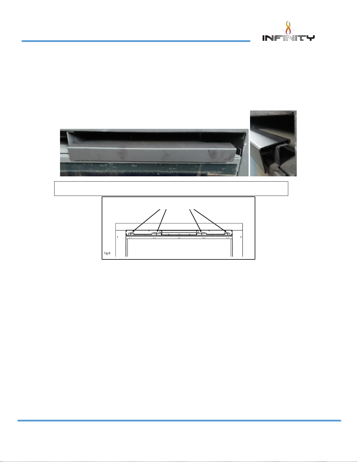
To clean the glass panel, remove the two fixing covers and the four M4 nuts fixing the glass
clamp to the glass panel. (See Fig 8). With the nuts removed, pull the glass clamp clear of the
four studs. Finally lift the glass panel out of the bottom glass fixing.
Using a damp cloth and warm soapy water will remove a majority of stains. For more substantial
marking we recommend the use of ceramic hob cleaner. These are available from all leading
super markets. The brands of hob cleaner we have tested and found suitable are “Hob brite” &
“Bar Keepers Friend”. Ensure the glass is dry and re-assemble.
Note- Never operate the appliance when the glass panel is removed or broken. The glass may discolour quickly
when first installed, and it should be cleaned. This is due to the burning of the refractory fuel bed shapes.
To Clean the Pilot assembly. Remove the four M4 nuts and glass clamp (See Fig 8). Carefully lift
the glass panel from within the bottom location. Remove the log and bark chip shapes. Lift out
the air tray assembly from within the burner shelf.
The pilot is located on the right hand side of the appliance, remove any debris in or around the
pilot head and the aeration hole. This can be achieved using the nozzle of a vacuum cleaner. It
is advisable not to blow the debris within the pilot head or aeration hole as this may cause more
of a restriction and not rectify the problem.
Note-Take care when cleaning in this area so as not to damage the pilot assembly.
4 off glass fixing nuts
Fixing cover slides over the top of the fixing bracket and hooks over the back of the bracket
Page 11
P a g e | 10
LT7185 Iss 2 (06/18)
780 HD USERS INSTRUCTIONS
Cleaning the fuel bed shapes. (Please refer to customer protection information on page 2 of this
booklet before cleaning or replacing any refractory materials).
The fuel bed components are delicate and they should be handled with great care. They can
be brushed very gently with a soft brush to remove dust or any deposits. A vacuum cleaner may
only be used after the loose components and moulded shapes have been removed from the
780 HD fire box.
It is important that all fuel bed shapes are positioned as shown in these instructions.
Fuel Bed Layout
Fuel bed lay out video can been found at:
http://www.charltonandjenrick.co.uk/780guide/
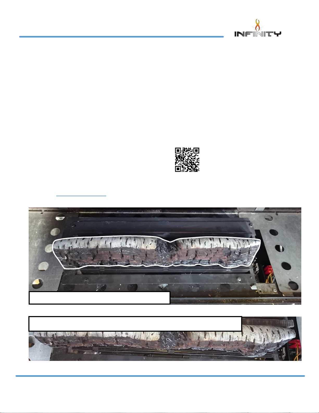
Birch Fuel bed
Firstly, place the air tray within the fire box shelf as shown.
The Log & bark shapes must be positioned in accordance to the following instructions to give
the correct flame picture & reduce the risk of glass staining.
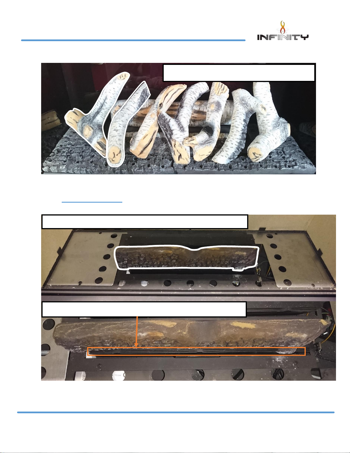
Slide the log piece behind the burner
Make sure not to cover the burner slots on the front burner
Page 12
P a g e | 11
LT7185 Iss 2 (06/18)
780 HD USERS INSTRUCTIONS
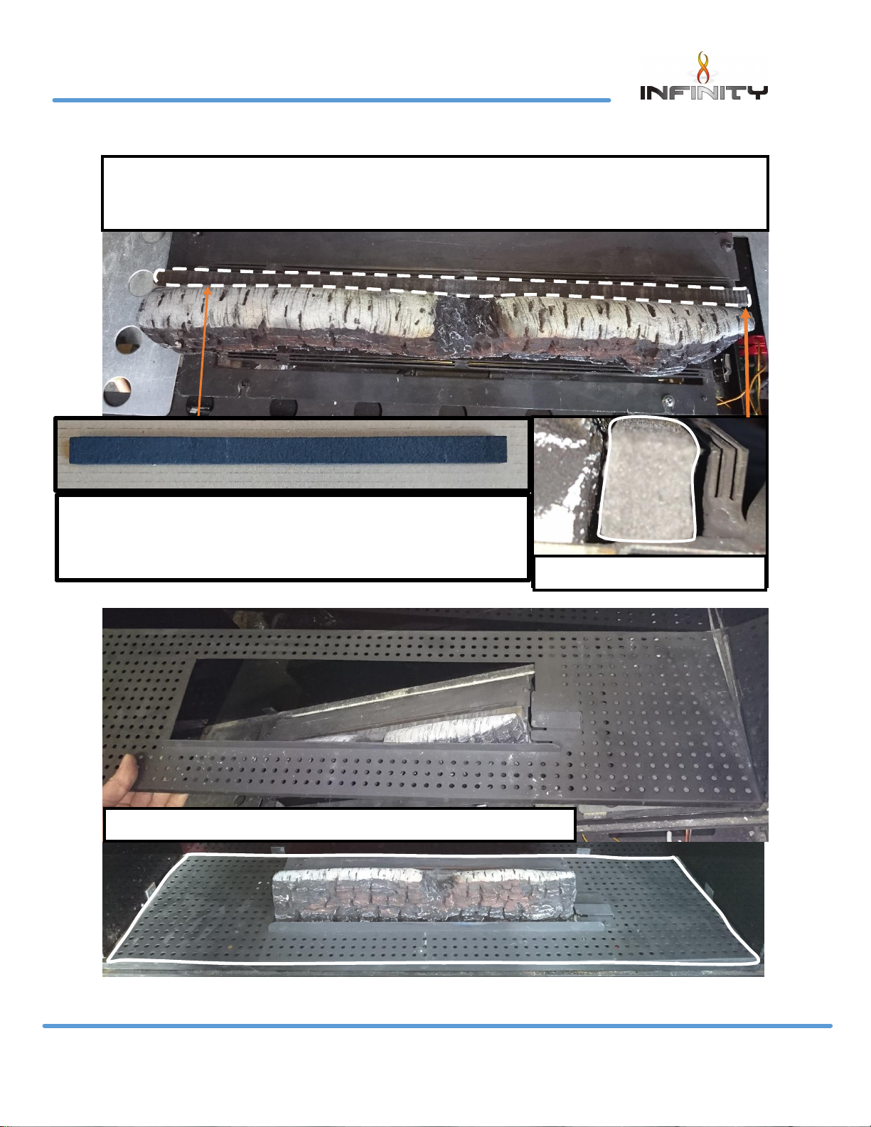
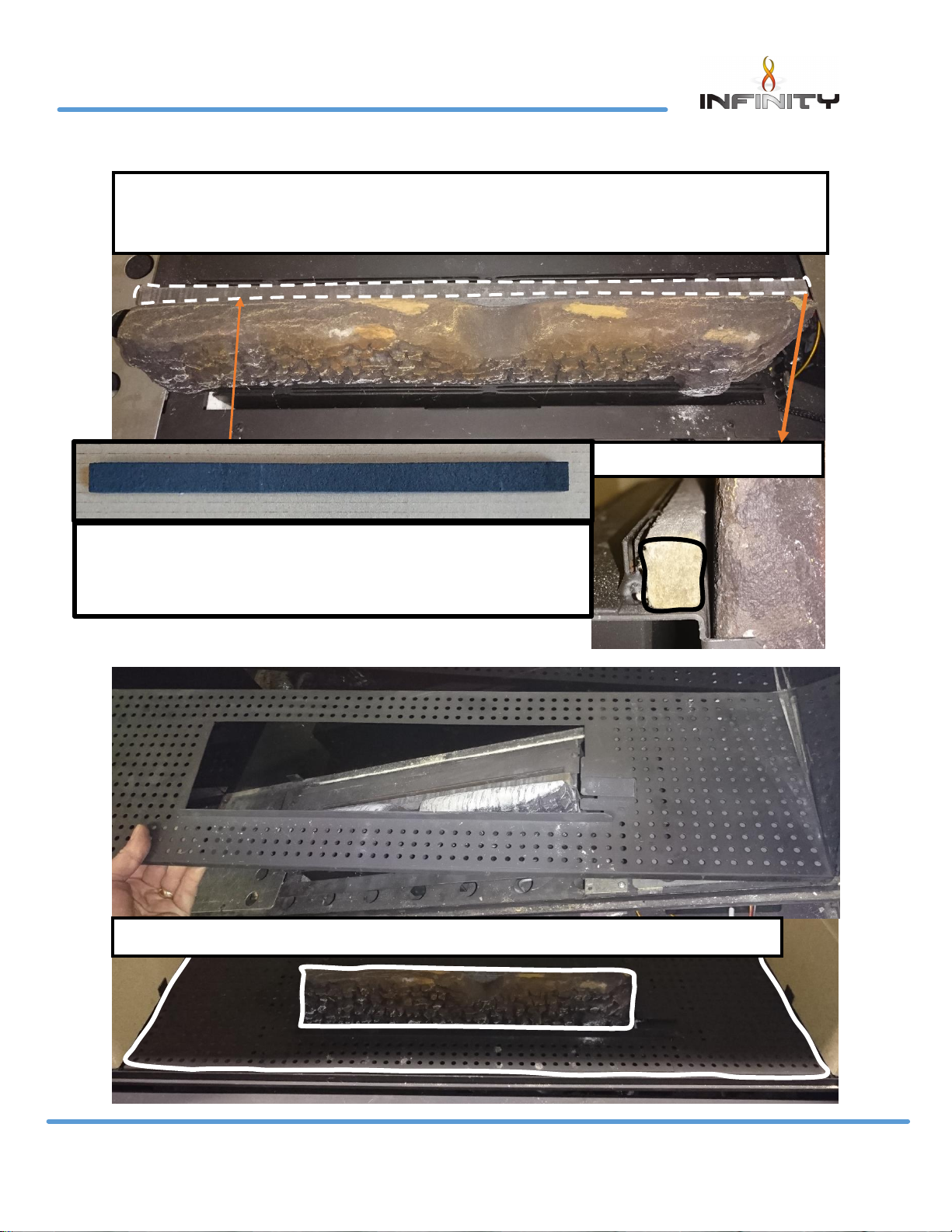
Slide ceramic strip (L: 380mm W:10mm H: 15mm) in behind Centre
log piece and in front of the burner slots on the rear burner
Side on view
Slide air tray in to place make sure it is central
Fit the burner shield behind the Centre log and in front of the
burner ports on the rear burner this must be fitted failure to fit this
will cause lighting issues when using the appliance.
Page 13
P a g e | 12
LT7185 Iss 2 (06/18)
780 HD USERS INSTRUCTIONS
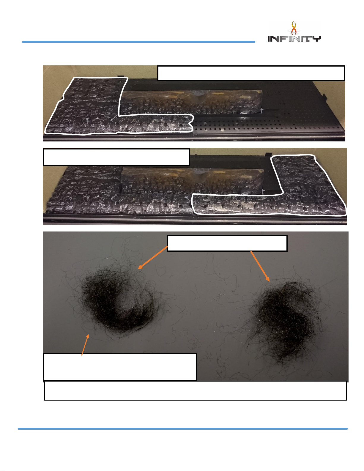
Slide the LH base ceramic piece in to place
Slide R/H base ceramic in to place
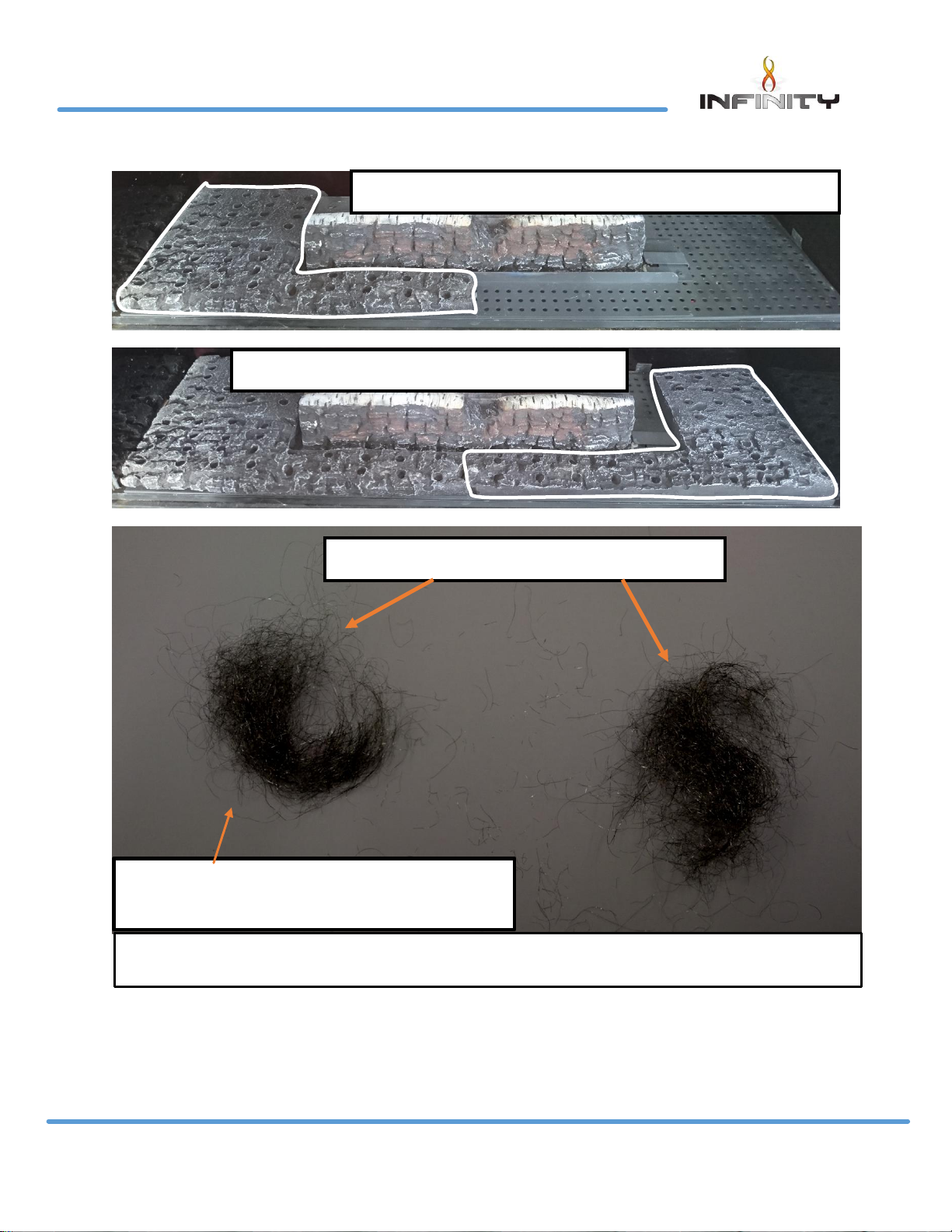
Split the pack of Emberglow in half
Keep one half of the Emberglow
for annual service
*Emabglow only used on Natural gas Appliance*
Page 14
P a g e | 13
LT7185 Iss 2 (06/18)
780 HD USERS INSTRUCTIONS
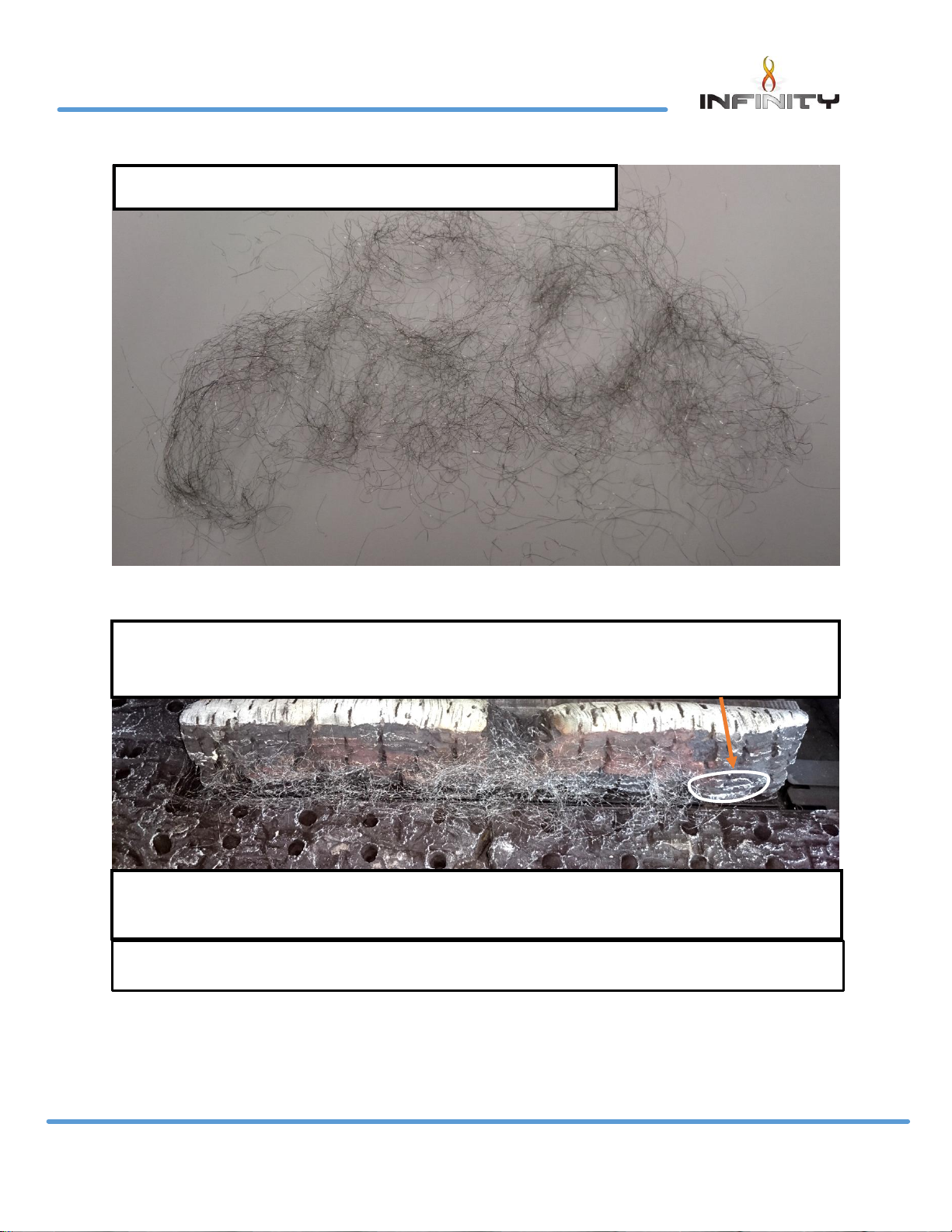
Stretch out half of the Emberglow like a net
Lay the stretched out Emberglow along the front burner slots
avoiding going pass the cross lighting lug
Avoid getting the Emberglow fibers near the pilot as it is conductive
material
*Emabglow only used on Natural gas Appliance*
Page 15
P a g e | 14
LT7185 Iss 2 (06/18)
780 HD USERS INSTRUCTIONS
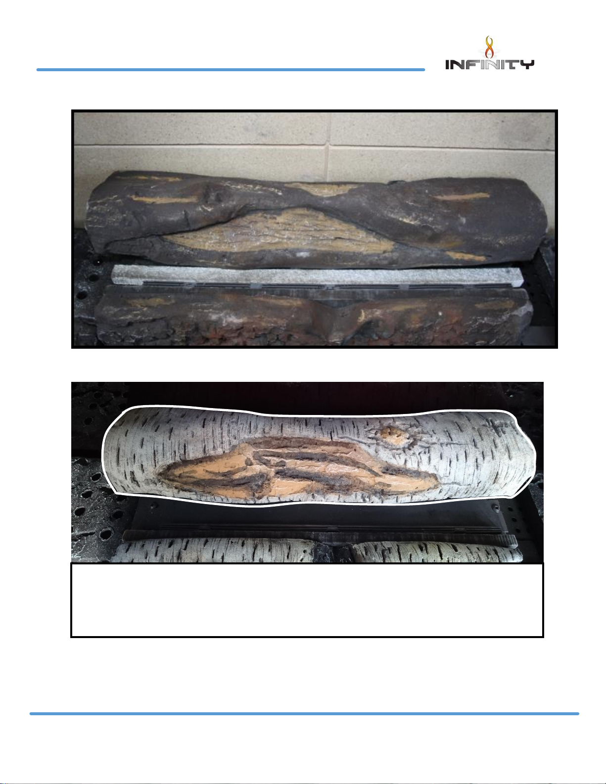
Place the second burner shield laying flat behind the rear burner as shown above
Lay the Centre back log along the back of the rear burner making
sure it is in the Centre and this pattern shown is facing forward and
the flat edge is against the rear liner
Page 16
P a g e | 15
LT7185 Iss 2 (06/18)
780 HD USERS INSTRUCTIONS
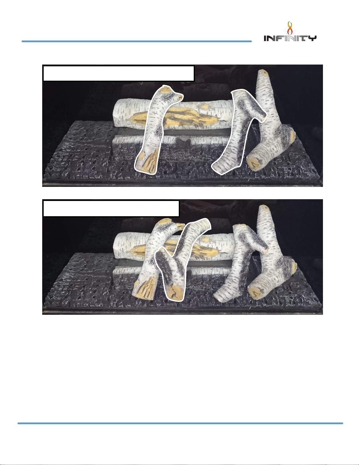
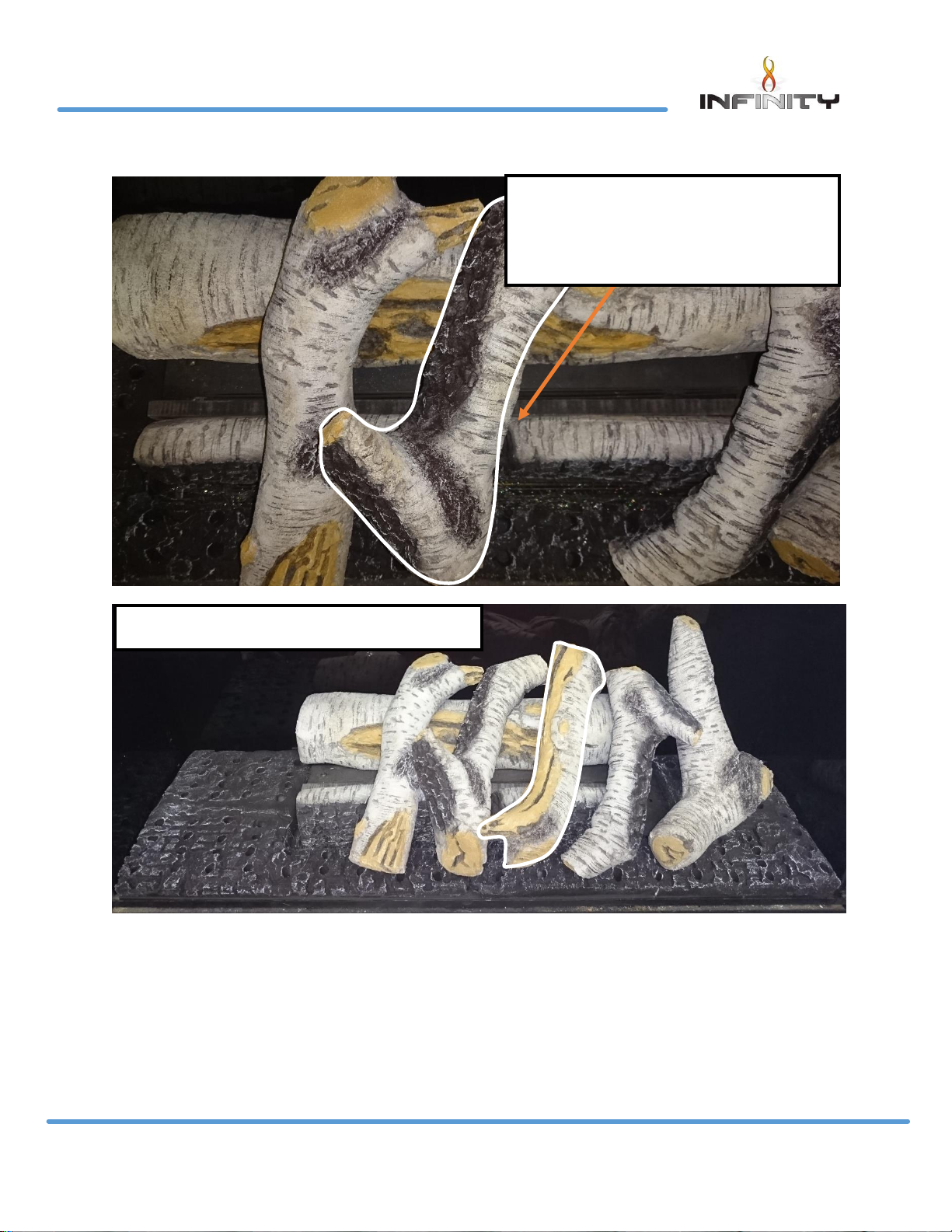
Place the two log shapes as shown
Place the 1 log shapes as shown
Page 17
P a g e | 16
LT7185 Iss 2 (06/18)
780 HD USERS INSTRUCTIONS
This Centre log must be in line
with the cross lighting lug on
the front Centre log
Place the 1 log shape as shown
Page 18
P a g e | 17
LT7185 Iss 2 (06/18)
780 HD USERS INSTRUCTIONS
Walnut fuel bed
Place the final 2 log shapes as shown
Slide the Centre log shape behind the front burner
Avoid placing the Centre log over the burner slots
Page 19
P a g e | 18
LT7185 Iss 2 (06/18)
780 HD USERS INSTRUCTIONS
Slide ceramic strip (L: 380mm W:10mm H: 15mm) in behind Centre
log piece and in front of the burner slots on the rear burner
Side on view
Slide air tray in to place make sure it is central and sitting flat
Fit the burner shield behind the Centre log and in front of the
burner ports on the rear burner this must be fitted failure to fit this
will cause lighting issues when using the appliance.
Page 20
P a g e | 19
LT7185 Iss 2 (06/18)
780 HD USERS INSTRUCTIONS
Slide the LH base ceramic piece in to place
Slide R/H base ceramic in to place
Split the pack of Embaglow
Keep one half of the Embaglow for
annual service
*Emabglow only used on Natural gas Appliance*
Page 21

P a g e | 20
LT7185 Iss 2 (06/18)
780 HD USERS INSTRUCTIONS
Stretch out half of the Embaglow like a net
Lay the stretched out Embaglow along the front burner slots
avoiding going pass the cross lighting lug
Avoid getting the Embaglow fibers near the pilot as it is conductive
*Emabglow only used on Natural gas Appliance*
Page 22

P a g e | 21
LT7185 Iss 2 (06/18)
780 HD USERS INSTRUCTIONS
Lay the Centre back log along the back of the rear burner making sure it is in
the Centre and this pattern shown is facing forward and the flat edge is
against the rear liner
Place the one log as shown
Place the two log shapes as shown
Page 23

P a g e | 22
LT7185 Iss 2 (06/18)
780 HD USERS INSTRUCTIONS
Place the 1 log shapes as shown
Place the 1 log shape
Page 24

P a g e | 23
LT7185 Iss 2 (06/18)
780 HD USERS INSTRUCTIONS
This Centre log must be in line with the
cross lighting lug on the front Centre log
Place the final 2 log shapes as shown
Page 25

P a g e | 24
LT7185 Iss 2 (06/18)
780 HD INSTALLATION INSTRUCTIONS
Technical Specification
Model
Gas
CAT
Gas
Type
Working
Pressure
Front
Injector
Rear
Injector
Gas
Input
NOX
Class
Oxy
Pilot
Country
780 HD
NG
I2H
Natural
Gas
20
mbar
Mrk
220
Mrk
290
6.6 KW
Gross
5
2550
NGR
GB, IE
780 HD
LPG
I3P
LPG
37
Mbar
Mrk
92
Mrk
94
6.8 KW
Gross
5
9264
LPG
GB, IE
Efficiency Class 1
Gas Inlet Connection Size 8mm
Handset Replacement Batteries 4 x AAA 1.5V
Power Supply Type Plug – Input : 100-240 VAC 50/60 Hz, 0.2A
Note : The efficiency of the appliance has been measured as specified in BS7977-1 2009+
A1:2013 and the net efficiency rate is 71.8%. The gross calorific value of the fuel has been used
for this efficiency calculation. Gastec have certified the test data from which it has been
calculated. The efficiency value may be used in the UK Government’s Standard Assessment
Procedure (SAP) for energy rating of the dwelling. Within the appliance packaging will be an
outlet restrictor, this is there to achieve the maximum efficiency. This, however may not be fitted
due to the flue underperforming.
Page 26

P a g e | 25
LT7185 Iss 2 (06/18)
780 HD INSTALLATION INSTRUCTIONS
Packaging Check List
1 x Glass Panel
1 x Air Tray Assembly
1 x Boxed Fuel Bed
1 x Transformer Plug
1 x Battery Holder
1 x Emergency Power Battery Adaptor
1 x RF Handset
4 x AAA 1.5V Batteries
Siting the Appliance
Regulation and warnings
This appliance must only be installed in Great Britain and Eire.
The appliance is suitable for use on natural gas or LPG only.
When fitted in the GB the fire does not normally require purpose provided ventilation
In GB it is the law that all gas appliances must be installed by a competent person GAS SAFE
registered installer, in accordance with the Current Gas Safe (installation and user) Regulations.
All relevant parts of the local and national building regulations and all relevant
recommendations of the following British standards. Failure to do so could lead to prosecution.
The following are relevant codes of practice and British Standards:-
B.S 5871
B.S 5440 Part 1 & Part 2
B.S 6891
This appliance must be installed to current versions of the above standards and include any
relevant amendments to:-
The building regulations issued by the department of the environment.
The building standards (Scotland) (Consolidated) Regulations issued by the Scottish
development office.
Eire the appliance must be installed by a competent person and installed in accordance with
the current edition of I.S 813 document gas installation, the current building regulations and the
current ETCI rules for electrical installation, if appropriate.
Page 27

P a g e | 26
LT7185 Iss 2 (06/18)
780 HD INSTALLATION INSTRUCTIONS
Prior to installation ensure that the local distribution conditions (identification of the type of gas
and pressure) and adjustment of the appliance are compatible G20 @ 20 mbar for natural gas
and G31 @ 37 mbar for LPG.
The front of the fire act as a dress guard, conforming to BS 1945 (1971) and satisfies the heating
appliance regulations (1991). However, a guard conforming to BS6539 (1984) must be used to
protect young children, the elderly or infirm.
This appliance incorporates a safety device in form of an oxygen depletion system. It must not
be adjusted or put out of operation. This is a non – serviceable item and must be exchanged as
a complete assembly using only the original manufacturer’s part. A suitable proprietary fire
surround with a 150 degree C minimum rating is required.
Class One
That is a conventional brick or stone chimney as used for a solid fuel appliance with an effective
cross sectional dimension of 225 x 225mm or a lined flue with a minimum diameter of 125mm.
The chimney must have a minimum effective height of at least 3 metres. Any permanent flue
restriction or variable damper are to be removed or locked fully open. The chimney should be
swept prior to installation if it has previously been used with a gas appliance or if it is a new
installation.
The 780 HD is designed to be fitted into a class one flue with a fire place which will require a
50mm rebate. The other option is hole in the wall which can be plastered up to the edge of the
fire place frame or fitted with wall mounted non-combustible slips. The two methods will require
different size apertures.
Builder’s opening aperture size when fitted in conjunction with a 50mm rebated surround
Page 28

P a g e | 27
LT7185 Iss 2 (06/18)
780 HD INSTALLATION INSTRUCTIONS
Open the firebox aperture as of the sizes stipulated in the previous section (50mm rebated
surround). Please note the fire box height from the floor may well vary dependent on the
fireplace surround design. Check the fireplace details first. Slide the fire box back into the
catchment area and secure the fire box against the front face of the chimney breast. Fit the fire
place frame to the fire box flange. The fireplace surround can now be constructed.
The 780 HD can be installed using three different methods when going hole in the wall.
A- Hole in the wall using none combustible slips.
B-Dry lined hole in the wall.
C-Wet plaster hole in the wall.
Page 29

P a g e | 28
LT7185 Iss 2 (06/18)
780 HD INSTALLATION INSTRUCTIONS
A- B-C / Builder’s opening aperture size when fitting hole in the wall plaster edge or slips.
A-Hole in the wall using none combustible slips.
Page 30

P a g e | 29
LT7185 Iss 2 (06/18)
780 HD INSTALLATION INSTRUCTIONS
Using rawl plugs and wood screws retain the fire box via the 6mm holes within the slip brackets.
None combustible slips can now be fitted up to the edge of the fire place frame.
B-Dry lined hole in the wall.
Using superlux heat proof board up to the edge of the fireplace frame.
The top shaded area below should be one piece with no joints.
Page 31

P a g e | 30
LT7185 Iss 2 (06/18)
780 HD INSTALLATION INSTRUCTIONS
Open the aperture size to accommodate the fire box as out lined at the beginning of the
section. With the height of the opening established and support for the fire box in place, take
out a further area of the plaster board lining to expose the inner brick work face of the chimney
breast as out lined in Fig 1.
The exposed area should be 887mm from the base of the fire and 1052mm in the width. With the
slip bracket attached to the fireplace frame. Secure the fire box back against the inner brick
work face of the chimney breast using rawl plugs and wood screws.
New plaster board can now be fitted to cover the exposed metal work, making sure that no
plater joints are positioned directly above the unit as highlighted in the Fig 2 above.
C-Wet plaster hole in the wall.
When the chimney breast front has been finished using wet plastered method and the total
thickness of the bonding plus finishing plaster is less than 12mm. The following method will need
to be applied.
Fit the fire box using the guidance stipulated earlier in the section when fitting the fire box with
none combustible slips. With the fire box secured fit 15mm thick plaster board section to cover
the complete front area of the chimney breast up to the forward projected edge of the firebox
frame. Please note avoid any plaster board joints directly above the unit.
Page 32

P a g e | 31
LT7185 Iss 2 (06/18)
780 HD INSTALLATION INSTRUCTIONS
Checking the flue fire opening and fire opening.
Check that the chimney conforms to the required specification as previously stated. Examine
the condition and carry out any remedial work including removing any debris from the base.
If the flue has been used for solid fuel it should be swept prior to installation.
Prior to installing the appliance a smoke test (using a bomb) should be carried out to check that
satisfactory smoke clearance has been established. If all the smoke is not drawn into the flue,
pre-heat the flue with a blowtorch or similar and retest. If there is any uncertainty examine for
the cause and if necessary seek expert advice.
When installing the appliance against a dry lined plasterboard wall ensure that the void
between the plaster board and wall is sealed with a non-combustible material.
No combustible material should be fitted inside the fireplace opening.
Installation with a flexible liner
The 780 HD is designed for installation within the masonry chimney with or without a flexible line.
If the flexible liner option is required the following two methods should be followed.
Method 1
A 125mm minimum diameter liner conforming to BS 715 may be used. Providing a suitable
sealing plate is fitted to the base of the liner and the appliance does not restrict the opening
into the liner. Ensure a smooth lead into the flue way and no combustible materials are used. A
void of 50mm must be maintained from the top of the firebox into flue.
Method 2
Using the flexible liner gather hood (Part No A-0662). Using again 125mm minimum diameter liner
conforming to BS 715, route the flexible liner within the masonry as of the requirements stipulated
by the liner manufacturer.
Attach the gather hood to the liner using a suitable fixing at a height that clears the firebox
assembly.
Remove the inner and outer inspection plate situated within the rear of the fire box assembly
(Please see Fig 1).
Page 33

P a g e | 32
LT7185 Iss 2 (06/18)
780 HD INSTALLATION INSTRUCTIONS
Offer the fire box assembly within the masonry aperture at the same time guiding the gather
hood within the guides situated on the top of the fire box (Please see Fig 2). Engage the hood
studs within the slotted holes and secure using the three M4 nuts provided within the gather
hood kit.
Page 34

P a g e | 33
LT7185 Iss 2 (06/18)
780 HD INSTALLATION INSTRUCTIONS
Installation of the Appliance
Optional Wi-Fi Kit Installation
The Kit contains the following components:
• 1 x Wi-Fi Dongle.
• 5 x Self adhesive aluminum clips.
• 1 x Wi-Fi lead.
• 2 x M3 nuts and washers
Remove the 2 off screws retaining the ECU cover from the LH
side of the burner carrier. Lift off the cover plate to allow
access to the ECU unit.
Within the ECU unit will be a clear port connection labeled
“SENSOR.” Inset the Wi-Fi connector plug within the open port.
Connect the opposite end to the lead within the Wi-Fi Dongle.
Set up video can be found at:
Apple: http://www.charltonandjenrick.co.uk/appleguide/
Android: http://www.charltonandjenrick.co.uk/androidguide/
Page 35

P a g e | 34
LT7185 Iss 2 (06/18)
780 HD INSTALLATION INSTRUCTIONS
With the dongle connected to the lead, locate the unit within the two M3 studs position on the
left hand side of the fire box. When positioning the Wi-Fi unit it is important to have the cable
socket facing the rear of the fire box. (Please note when installing the dongle with appliances
using a four sided trim option. The studs with the base of the fire box unit should be used. Failure
to do this could result in over heating issues).
Retain the Wi-Fi dongle receiver using the nuts and washers provided.
Finally using the aluminum clips provided retain the excessive lead to the base of the fire box.
Page 36

P a g e | 35
LT7185 Iss 2 (06/18)
780 HD INSTALLATION INSTRUCTIONS
Gas supply routing.
Check the gas run to assess that the gas supply is capable of providing the required amount of
gas and is in accordance with the rules in force.
Soft copper pipe can be used to install the appliance. Soldered joints can be used only
externally of the appliance.
The appliance is supplied with a factory fitted isolation device to allow for an 8mm copper
connection. No further isolation point is required.
The new gas line must be purged of any
debris, prior to final connection to the
appliance.
Gas inlet isolation device is located on
bottom left hand side of the fire box, the
gas supply entry point is positioned at the
rear bottom on left hand side. With the
appliance fixing kit is a 35mm round seal
(Please see fig 3), this should be cut and
fitted over the 8mm copper at the point
the gas supply entry into the appliance
assembly. The gas inlet cover will need to
be removed to gain access to the connection. (Please see fig 4).
The gas inlet isolation device must be
angled to allow access to the grub screw
and gas test nipple. (Please see fig 3).
Angle the inlet isolation
device to allow access
to the grub screw and
test nipple
35mm round seal will need
to be cut and engaged
within the firebox to form an
air tight seal around the
inlet gas supply pipe
Page 37

P a g e | 36
LT7185 Iss 2 (06/18)
780 HD INSTALLATION INSTRUCTIONS
Power lead routing
The power supply for this appliance is provided via AC power adaptor 230 VAC. The main cable
terminates the rear Right hand side of the fire box. The length of the cable provided with the
appliance is 1.65 metres. Care must be taken when siting the fire box not to trap the exposed
main cable within the builders opening.
Note: the power cable link to the transformer must be accessible for repairing handset and use
with the battery holder
The cable can be routed using the following two methods,
Method 1
Passing the cable through the side of the chimney breast. It is good practice to run the cable
within a sleeve of at least 15mm internal diameter, sealing the sleeve using a suitable sealant at
the point the sleeve / cable terminates the chimney masonry.
Method 2
Remove a channel out of the outer skin of the Dry / wet plaster of the chimney breast up to the
main power point. Again it is good practice to run the cable within a sleeve of at least 15mm
internal diameter.
With power points that exceed the 1.65 metre distance, an optional 2.0 metre extension cable is
available Part No 7147.
The cable system consists of retro fitting plug sockets which offers the following options. (Please
see figure 5).
Page 38

P a g e | 37
LT7185 Iss 2 (06/18)
780 HD INSTALLATION INSTRUCTIONS
The battery manual override option is a back supply in case of a power failure / power cut to
the property. The battery holder and adaptor lead are provide within the packing of the
appliance. (Please note that the “C” cell batteries are not included). It is good practice to
demonstrate the battery option to the customer during the commissioning process.
Fire Box Installation
Note: - When installing the appliance with a 3 inch (75mm) rebated surround the option 30mm
spacer frame Part No 7570 will be required.
The fire box assembly can be retained using the following two methods.
Secure the firebox when fitted with 50mm rebated surround
Using suitable rawl plugs and wood screws retain the fire box using the four 6mm holes within the
firebox flange. With the fire box secured, slide the fireplace frame assembly over the four 4mm
studs projecting forward from the fire box flange. Fix the frame to the fire box using the M4 nuts
and the nut spinner provided within the appliance packaging. (Please see figure 6)
Page 39

P a g e | 38
LT7185 Iss 2 (06/18)
780 HD INSTALLATION INSTRUCTIONS
Hole in the wall.
For hole in the wall installation, two additional fixing brackets will be needed that are attached
to the fireplace frame LH and RH. Attached the two brackets using the 6 off fixing screws
provided with the kit. Secure the complete assembly using suitable rawl plugs and wood screws
via two 6mm holes within the wall fixing brackets. (Please see Figure 7).
(Please Note). The fireplace frame is supplied with the slip guides attached. To improve the
overall appearance of the appliance the guide brackets can be detached by removing the No
6 shelf tapping screws from within the fireplace frame assembly.
Hole in the wall fixing brackets.
Attach to the frame assembly using
the six self-tapping screws provided
6mm fixing holes
Keyhole slot must be fully engaged to maintain
the 10mm clearance between the glass fixing
bracket and the bottom internal edge of the
fireplace frame
Important
When fitting the fireplace frame the studs need
to be fully engaged to the top of the keyhole
slot (as shown). If this is not fully engaged, it
may cause ignition and outing issues
Page 40

P a g e | 39
LT7185 Iss 2 (06/18)
780 HD INSTALLATION INSTRUCTIONS
Fixing the glass fascia
Using A-B-C / Builder’s opening aperture size when fitting hole in the wall plaster edge or slips
instructions on page 28 to place fire on the wall.
Secure fire in place to the wall with 4 suitable screws and rawl plugs (not provided)
Screws here to secure fire in place
Page 41

P a g e | 40
LT7185 Iss 2 (06/18)
780 HD INSTALLATION INSTRUCTIONS
Slide fixing frame for the glass fascia over the studs and secure in place with 4 fixings nuts
(provided in kit)
Use the fixing nuts here
Make sure the heat deflector is fitted at the top of the fire
Page 42

P a g e | 41
LT7185 Iss 2 (06/18)
780 HD INSTALLATION INSTRUCTIONS
Perform the spillage test at this point before fitting the glass fascia. Refer to the spillage test
procedure on page 45 for guidance on how to perform this test on this appliance.
Now the fire is ready for the glass fascia to be hooked on using the studs on the fascia sliding
them in to place on the slots provided in the side of the fixing frame.
Once fitted make sure that the heat outlet hole in the fascia is at the top to allow for heat
disapation
These studs are on both sides of the fascia these slide in to the slots on the
slide of the fixing bracket
Page 43

P a g e | 42
LT7185 Iss 2 (06/18)
780 HD INSTALLATION INSTRUCTIONS
Commissioning the Appliance
Checking gas soundness and running pressure.
Turn on the supply to the appliance and check for soundness in accordance with the current
codes of practice.
Turn off the gas supply at the external isolation valve.
Remove the pressure test point screw from the inlet elbow and connect the pressure gauge.
Turn on the gas to the appliance at the isolation valve.
Light the appliance as described in the user instruction section. Page 4 turn on (startup).
Check the inlet pressure is 20 mbar +/- 1.0 mbar for natural gas or 37 mbar +/-1.0 mbar for LPG.
with other appliances running.
Turn off gas supply, at the isolation valve. Disconnect the pressure gauge and replace the
pressure test point screw.
Turn on the appliance and check the pressure test point for soundness with detection fluid.
Refit the gas cover as shown in Fig 4.
Page 44

P a g e | 43
LT7185 Iss 2 (06/18)
780 HD INSTALLATION INSTRUCTIONS
Fuel Bed Layout.
Fuel bed layout should be fitted using the guidance stipulated on pages 9-15 of the User
Instruction section.
Fit Glass Panel.
Due to transit protection, the glass panel is packed with a protective sleeve within the packed
appliance. Special care should be taken when removing the glass panel from the packing. The
top fixing is attacked to the fire box via 4 off M4 fixing nuts. Remove the nuts and remove the top
fixing bracket. (Please see fig8 within the user instruction section).
Locate the glass panel within the bottom retaining slot and push back against the seals. (Please
see Fig 11).
Non reflective glass option.
The non-reflective glass has no print on the glass due to this there is a inner frame provided to be
fitted before the glass panel.
Slide the inner frame into the glass channel and push in to place ensuring the tabs are sitting on
top of the firebox(see below) ensure the frame is central and there is a even gap either side of
the frame (between the side of the firebox and the tabs of the frame)
Slide the glass in front of the frame and push in to place making sure
that the glass is pushed in to the glass channel properly and sits in the
bottom of it and that the inner frame is still central.
Make sure that the gap
here is the same on both
sides of the frame
Page 45

P a g e | 44
LT7185 Iss 2 (06/18)
780 HD INSTALLATION INSTRUCTIONS
Position the top fixing bracket over the top edge of the glass panel and slide over the two M4
studs.
Using the two M4 nuts previously removed. Tighten the top glass fixing using the nut runner
provided with the appliance being careful not to over tighten the glass as this will cause
breakages.
Position the top fixing bracket over the top edge of the glass panel and slide over the four M4
studs.
Using the four M4 nuts previously removed. Tighten the top glass fixing using the nut runner
provided with the appliance.
Make sure that the glass is
sat in the bottom of the
glass channel
Push the glass in to place
so it sits flat against the
Page 46

P a g e | 45
LT7185 Iss 2 (06/18)
780 HD INSTALLATION INSTRUCTIONS
Spillage Test Procedure.
Light the appliance on maximum setting.
Close all the doors and windows.
After five minutes fit the smoke match within match holder and position as illustrated in Figure 13
with the head of the match just inside the inlet air channel.
Run the match along the edge of the inlet air channel. All smoke must be drawn into the inlet
channel if the spillage test is satisfactory.
If spillage occurs wait a further five minutes and repeat the test.
Repeat the test with doors open and with any extractor fans in other rooms in operation.
If spillage is detected the cause must be discovered and the fault corrected. If the fault cannot
be corrected, disconnect the fire from the gas supply and seek expert advice. Spillage can be
caused by a restriction in the flue system, down draught or insufficient ventilation into the room
where the fire is installed.
Advise The Customer.
The glass front of this fire acts as a dress guard conforming to BS 1945 (1997) and satisfies the
heating appliance regulations (1991) however; a fireguard conforming to BS6539 (1997) must be
used to protect young children, the elderly, or infirm.
During initial “burn off”, an odour may be evident during the first few hours of use. This is due to
the surface coating on the metal work “burning off”. The odour produced is harmless and will
disappear after a short period of time.
Any debris should be cleared from the appliance.
The appliance should be serviced annually by a Gas Safe registered engineer in accordance
with the Service instruction section.
Page 47

P a g e | 46
LT7185 Iss 2 (06/18)
780 HD INSTALLATION INSTRUCTIONS
Point out the position of the power source for the appliance, plus demonstrate using the
additional battery holder and adaptor lead, the battery backup option. (“C” cell batteries not
included within this appliance).
Demonstrate the lighting and extinguishing procedures to the user and the removal and refit of
the glass panel for cleaning and the fitting of the battery back up kit.
Hand these instruction over to the user along with the battery holder, adaptor lead plus M4 nut
runner for the removal of the glass panel.
Please be aware that the non-reflective glass may in some lights and from some angles have a
blue tinge to it this is perfectly normal. Also be aware that if the glass liners are fitted in the fire
with the non-reflective glass you will still have a reflection in the glass liners.
It is a requirement that the gas fire is installed and commissioned to the manufacturer’s
instructions and the data fields on the commissioning checklist completed in full.
Annual Service Requirement.
General
Servicing should be carried out annually by competent person whose name appears on the gas safe
register. All Gas Safe engineers should possess an ID carrying the logo below.
Before commencing any service or replacement of part, turn off the gas supply to the
fire. After servicing check for gas soundness.
When ordering spare parts please quote the appliance name and serial number.
This product should be serviced regularly to optimize its safety, efficiency and
performance. The service engineer should complete the relevant Service Record on the
Benchmark Checklist after each service.
Check for debris
At least once a year check for debris in the catchment area behind the fire and in the flue way.
To undertake this check the following procedure should be followed.
Remove the four M4 nuts fixing the glass clamp to the glass panel. (See Fig 8). With the nuts
removed, pull the glass clamp clear of the four studs. Finally lift the glass panel out of the bottom
glass fixing.
Remove the log shapes.
Lift out the air tray assembly from within the fire box shelf.
Remove the four screws retaining the gas inlet plate and the ECU cover.
Page 48

P a g e | 47
LT7185 Iss 2 (06/18)
780 HD SERVICE / FAULT FINDING INSTRUCTIONS
Shut off the restrictor elbow and disconnect the 8mm inlet nut.
Switch off the mains supply from the main supply plug socket.
Undo the two M3 nut retaining the ECU unit and remove the connection bracket plus
disconnect the mains supply cable from ECU.
Take out the three screw retaining the burner tray assembly and lift out of the fire box shelf
taking care not to damage the panels.
Remove the two side liner fixing bracket LH & RH which are situated in the roof of the fire box
assembly.
Carefully remove the LH & RH side panels.
Remove the rear panel from within the fire box.
Finally remove the eight screws from the inner and
outer inspection covers. (Please see figure 1)
With the covers removed. The catchment area at the rear of the fire box can now be inspected
for debris. With the aid of a mirror via the back of the box check the path of the flue for any
restrictions. Re-assemble in reverse order.
Pilot Linting
Check the pilot aeration hole for linting, use a vacuum clearer nozzle taking care not to
damage the pilot head. Do not blow compressed into the pilot as this can lodge debris in the
pilot body.
Electrode Gap
The electrode gap should be 4mm from the tip of the thermocouple probe head to the end of
the electrode wire.
Spillage test
Follow the procedure stipulated on page 45 of the installation instruction section.
Page 49

P a g e | 48
LT7185 Iss 2 (06/18)
780 HD SERVICE / FAULT FINDING INSTRUCTIONS
Fault Finding Charts
Page 50

P a g e | 49
LT7185 Iss 2 (06/18)
780 HD SERVICE / FAULT FINDING INSTRUCTIONS
Page 51

P a g e | 50
LT7185 Iss 2 (06/18)
780 HD SERVICE / FAULT FINDING INSTRUCTIONS
Page 52

P a g e | 51
LT7185 Iss 2 (06/18)
780 HD MAINTENANCE INSTRUCTIONS
Wiring Diagram
Attach to the
oxy pilot
Page 53

P a g e | 52
LT7185 Iss 2 (06/18)
780 HD MAINTENANCE INSTRUCTIONS
Maintenance
To Remove The Burner Carrier Assembly
Remove the glass panel as described on page 9 of the users instruction section.
Remove the Loose shapes and the air tray assembly.
Remove the four screws retaining the gas inlet plate and the ECU cover. (Please see Fig 1)
Shut off the restrictor elbow and disconnect the 8mm inlet nut.
Switch off the mains supply from the main supply plug socket.
Undo the M3 nut retaining the ECU unit and disconnect the mains supply cable connection.
Take out the three screw retaining the burner tray assembly and lift out of the fire box shelf
taking care not to damage the panels. (Please see Fig 2)
Page 54

P a g e | 53
LT7185 Iss 2 (06/18)
780 HD MAINTENANCE INSTRUCTIONS
Replacement Of The Gas Valve
Follow the sequence to remove the burner carrier assembly.
Disconnect the thermocouple from the rear of the gas valve.
Undo the three compression nuts securing the pipes to the gas valve and remove the two M4
nuts fixing the valve to the valve mounting brackets.
Clean, service or replace the gas valve.
Re-assemble in the reverse order.
Turn on the gas supply, check for soundness and re-commission the appliance.
Replacement Of The Injectors
Follow the sequence to remove the burner carrier assembly.
Undo the compression nut on the supply pipe.
Remove three two screws retaining the burner assembly to the carrier and lift away from the
injector.
Unscrew the locking nut holding the injector and silencer bracket on the burner carrier.
Remove injectors from assembly. Clean or replace injector.
Re-assemble in reverse order.
Replacement of the Oxy-Pilot Assembly
Note: If the pilot assembly is replaced it must be replaced by an identical unit from the same manufacturer and replaced as a complete unit.
Follow the sequence to remove the burner carrier assembly.
Undo the compression nut on the supply pipe at the pilot.
Carefully pull off the ignition lead.
Disconnect the thermocouple at the end of the gas valve.
Remove the two fixing screws attaching the assembly to burner carrier.
Re-assemble in the reverse order.
Page 55

P a g e | 54
LT7185 Iss 2 (06/18)
780 HD MAINTENANCE INSTRUCTIONS
Replacement of the burner Assembly
Remove the glass panel as described on page 9 of the users instruction section.
Remove the Loose shapes and the air tray assembly.
Undo the two fixing screws retaining the burner assembly with the carrier.
Lift the burner clear of the silencer and injector tip.
Clean or replace the burner assembly.
Re-assemble in reverse order.
Replacement of the Electronic Control Unit (ECU)
Note: Please note when changing the Electronic Control Unit the handset will need to be re-paired to the handset. (Please see replacement handset for pairing
details)
Remove the glass panel as described on page 9 of the users instruction section.
Remove the Loose shapes and the air tray assembly.
Switch off the mains supply from the main supply plug socket.
Undo the two M3 nuts retaining the ECU unit and remove the connection bracket.
Unplug the connection from the ECU board.
Re-assemble in reverse order.
Page 56

P a g e | 55
LT7185 Iss 2 (06/18)
780 HD MAINTENANCE INSTRUCTIONS
Replacement Handset
Follow the guide stipulated on page 7 of the users instructions “Changing the handset batteries”
to load the batteries into the new handset.
The replacement handset will need to be paired again to the ECU unit.
Pairing Handset
• Press eye button to wake handset
• Press &hold star button till menu is displayed –wait for box to fill
• Use wheel to scroll to display – “gas Fire”
• If not paired select – “PAIR”
• While fire is searching disconnect the power lead from the transformer
• Reconnect the transformer (should hear a beep to confirm power
reconnected)
• Fire should then be paired
If the handset not pairing try breaking the power link from the transformer – then get the handset
to pairing stage and then reconnect the transformer
To delete Pairing
Press and hold (approx. 5 seconds) until the menu graphic Completes (see Fig 3). This will
access the menu (see Fig 4). Use the selector wheel and select the “gas fire” option. Press &
simultaneously to delete the current channel. The handset will re-load to “NO DEVICE” see
Fig 4) screen. To complete pairing process follow the instruction on Page 31 of the installation
instruction “Pairing the handset”.
Page 57

P a g e | 56
LT7185 Iss 2 (06/18)
Short Spares List
Component
Part No
Burner Bar
3057
Front Injector Mrk 220 A NG
6283
Rear Injector Mrk 290 NG
3515
Front Injector Mrk 92 LPG
8131
Rear Injector Mrk 94 LPG
8132
Electrical Control Unit (ECU)
7150
Ignition Lead
6646
Handset RF
7191
780 HD Fuel Bed
Walnut: 7149
Silver Birch: 7499
Page 58

P a g e | 57
LT7185 Iss 2 (06/18)
Register your appliance online today to activate your
warranty
Page 59

P a g e | 58
LT7185 Iss 2 (06/18)
Page 60

P a g e | 59
LT7185 Iss 2 (06/18)
Page 61

P a g e | 60
LT7185 Iss 2 (06/18)
Page 62

P a g e | 61
LT7185 Iss 2 (06/18)
GAS FIRE COMMISSIONING CHECKLIST
This Commissioning Checklist is to be completed in full by the competent person who commissioned the gas fire
as a means of demonstrating compliance with the appropriate Building Regulations and then handed to the
customer to keep for future reference.
Failure to install and commission according to the manufacturer’s instructions and complete this Benchmark
Commissioning Checklist will invalidate the warranty. This does not affect the customer’s statutory rights.
* All installations in England and Wales must be notified to be Local Authority Building Control (LABC) either
directly or through a Competent Persons Scheme. A Building Regulations Compliance Certificate will then be
issued to the customer.
Site Requirements
Yes
N/A
Was the chimney checked to ensure it only serves one flue/fire, has no obstructions and is continuous?
Has any debris at the base of the chimney been removed?
For brick chimney installations is there enough depth for 12 litres of debris, or precast flues 2 litres of debris? (see instructions for
debris gap details)
Have damper and register plates been removed or locked in the fully open position ensuring correct size of flue is maintained?
If previously used for solid fuel has the chimney been thoroughly swept?
If the chimney is pre-cast has the inside of the flue been checked for extruded cement / sealant which must be removed?
Has the fire place been checked for under-floor air supply which must be sealed off?
Has the chimney been inspected prior to fitting the gas fire to ensure that it is in good condition?
Has the structure of the chimney been checked for leakage using a smoke pellet test? (See BS5440-1 for details).
Ventilation
Does the installation require any additional ventilation requirements as detailed in the manufacturer’s instructions?
Hearth Requirements- where fitted
Is the hearth constructed from non -combustible material?
Is the hearth a minimum of 12mm thick with a minimum floor to top surface of 50mm?(BS5871) or as per manufacturer’s
instructions?
Is the hearth for open fronted fires a minimum of 760mm wide and has 300mm projecting from the fire opening
(BS6871) or to manufacturer’s instructions?
Mounting height (where applicable) has the fire been installed to the correct mounting height- as per manufacturer’s instructions?
Firebox and Fuel Bed
Has the fuel bed, coals, pebbles etc. been fitted to manufacturer’s instructions?
Gas Supply
Has an isolation tap/restrictor inlet elbow been fitted for servicing?
Has the gas supply been thoroughly purged prior to connection to remove any debris?
Has a gas tightness test been completed prior to breaking into the gas supply and following completion of
Record burner gas pressure reading? If only the supply pressure is available a gas rate must be undertaken.(GSIUR REG26/9C)
Record dynamic inlet gas pressure (working pressure) reading (all gas appliances running)
Spillage test
Installation
Has the gas fire been installed and commissioned in accordance with manufacturer’s instructions?
Has the fire been installed with the correct clearance to combustible materials, as per manufacturer’s instructions?
The operation of the appliance and controls have been demonstrated to the customer including battery replacement where
applicable?
The manufacturer’s literature, including Benchmark Checklist and Service record has been explained and left with the customer?
Has the appliance been registered with the Local Authority as detailed on the Gas Safe web site and is a legal requirement and
forms part of the warranty?
Customer’s Signature: Commissioning Engineer’s Signature:
(To confirm satisfactory demonstration and receipt of manufacturer’s literature)
Page 63

P a g e | 62
LT7185 Iss 2 (06/18)
SERVICE RECORD
It is essential that your gas fire is serviced regularly and that the appropriate Service
Interval Record is completed. Service Provider
Before completing the appropriate Service Record below, please ensure you have carried out the service as described in
the manufacturer’s instructions. Always use the manufacturer’s specified spare part when replacing controls.
SERVICE 01
Date:
Engineer name:
Company name:
Telephone No:
Gas safe register No:
Comments:
Signature
SERVICE 02
Date:
Engineer name:
Company name:
Telephone No:
Gas safe register No:
Comments:
Signature
SERVICE 03
Date:
Engineer name:
Company name:
Telephone No:
Gas safe register No:
Comments:
Signature
SERVICE 04
Date:
Engineer name:
Company name:
Telephone No:
Gas safe register No:
Comments:
Signature
SERVICE 05
Date:
Engineer name:
Company name:
Telephone No:
Gas safe register No:
Comments:
Signature
Page 64

P a g e | 63
LT7185 Iss 2 (06/18)
Infinity 780 HD Packing List
Charlton and Jenrick Ltd
Unit D
Stafford Park 2
Telford
Shropshire
TF3 3AR
780 HD
NG
A-0607 – Glass liners fitted
A-0688 – Red Brick liners fitted
A-0689 – Vermiculite liners fitted
Pre- Fix
QV
780 HD
LPG
A-0783 – Glass liners fitted
A-0784 – Red Brick liners fitted
A-0785 – Vermiculite liners fitted
Pre- Fix
TB
Data badge and plate added
Burner tray / firebox assembly
Air test completed
Glass warning label (1409)
Grommet (1092)
Silicone sealing strip (4818)
Liners fitted (sides/rear/top)
AAA Batteries x 4
Remote control handset
Handset holder (7191)
Airtray ( tried for fitment in firebox)
Top glass retaining bracket fitted
7mm nut spinner (5435)
Glass tape added to all liner tabs (Only on glass liner version)
Side liner retaining brackets and spacers fitted
Oxy pilot gap checked (3mm-4mm)
Power lead fitted
Restrictor plate with label
Embaglow (NATURAL GAS ONLY)
C cell battery holder and warning label
9v Transformer and battery lead
Fixing cover brackets x 2
Inspector
Serial No
 Loading...