

Page 1
Reference Series
1300a
1 CHANNEL POWER AMPLIFIER
SERVICE MANUAL
Infinity Systems, Inc.
250 Crossways Park Dr.
Woodbury, New York 11797 Rev3 8/2008
Page 2

1300a Reference Series
1
- CONTENTS -
BASIC SPECIFICATIONS ………………..……….……..1
DETAILED SPECIFICATIONS ………….…..…….……..2
PACKAGING……………………….……..…..……………3
APPLICATIONS……………………………………………4
INSTALLATION/SETUP…………………………...…...…5
BASIC TROUBLESHOOTING..…….…….………………5
EXPLODED VIEW/PARTS LIST rev0……….…..……....6
EXPLODED VIEW/PARTS LIST rev1……….…..……....7
NOTE ON TOP COVER…………………………...…...…8
AMPLIFIER BLOCK DIAGRAM……………………..……9
P.C.B. DRAWINGS….………………………………..……10
ELECTRICAL PARTS LIST rev0……….………………. 12
ELECTRICAL PARTS LIST rev1…………….…………. 16
IC/TRANSISTOR PINOUTS rev0..……………………….19
IC/TRANSISTOR PINOUTS rev1..……………………….20
SCHEMATICS rev0………………...…………..……..…..21
SCHEMATICS rev1…………………...………..……..…..24
BULLETIN INF2008-02………….….…………………….27
TECH TIP INFTT2008-01………..……………………….28
Reference 1300a Basic Specifications
Output Power: 200W RMS x 1 @ 4 ohms; ≤1% THD + N
(14.4 VDC) 300W RMS x 1 @ 2 ohms; ≤1% THD + N
Signal-to-noise ratio: 85dBA (reference 1W into 4 ohms)
Dynamic power: 342W channels @ 2 ohms
Effective damping factor: 6.364 @ 4 ohms
Frequency response: 11Hz – 330Hz (-3dB)
Maximum input signal: 6.0V
Maximum sensitivity: 100mV
Output regulation: .11dB @ 4 ohms
Dimensions (L x W x D): 14-3/16" x 9" x 2-11/16" (361mm x 229mm x 69mm)
Fuse: 3 x 20A
Infinity continually strives to update and improve existing products, as well as create new ones. The specifications
and details in this and related Infinity publications are therefore subject to change without notice.
Page 3
1300a Reference Series
2
INFINITY REFERENCE 1300a AMPLIFIER SPECIFICATIONS
TEST VOLTAGE 14.4 +0.1V
Specification Rating Unit Remarks
Power Output 4ohm loads @50Hz ≥200W x 1 Watts
(stereo mode)for each . ch @<1.0%THD
(Unit:W)(LPF=22K)
Power Output 2ohm loads @50Hz ≥300W x 1 Watts
(stereo mode)for each .ch @<1.0%THD
(Unit:W)(LPF=22K)
THD Power 4 ohm loads
and 1MD@Reference (Unit:%) LPF=22K
≤0.1% @ 50Hz %
THD Power 2 ohm loads
and 1MD@Reference (Unit:%) LPF=22K
≤0.1% @ 50Hz %
Full rated power Distortion 1KHz LPF=22KHz ≤0.1% %
Signal/Noise Ratio
a: 1 watt into 4 ohms
b: full rated power (dB)
Input Sensitivity
Low Level Input( v) @:full rated power
Frequency response (Unit:-3dB) 11Hz~330Hz Hz -3dB
Bass Boost:(Unit:dB) @45HZ (±5Hz ) 0~6dB dB ±1dB
Idle Current ( @ 2ohm) 0.8A A ±0.15A
MAX current : rated power
(All channel 2 ohm loads)
DC Offset: ≤30mV mV
Damping Factor (4ohm):
Effective damping factor (4ohm): 6.364
Dynamic Power @ 2 ohms 342W Watts
Output Regulation @ 4 ohms 0.11dB dB
Remote Operating Voltages: 5V OFF 4V Volts ±1V
Turn on delay time 2 to 3 Seconds
Circuit Protection
a. Temperature
b. Speaker Short Circuit
c. Operating Voltage Range
Dimensions (L x W x H): 14-3/16" x 9" x 2-11/16"
(361mm x 229mm x69mm)
Fuses 20A x 3 A
85
dBA 1V signal input
100mV-6V
Volts ±20%
≤38A
A
>200
75 ±5 deg C
Yes
8~16V
Inches
mm
Page 4
1300a Reference Series
3
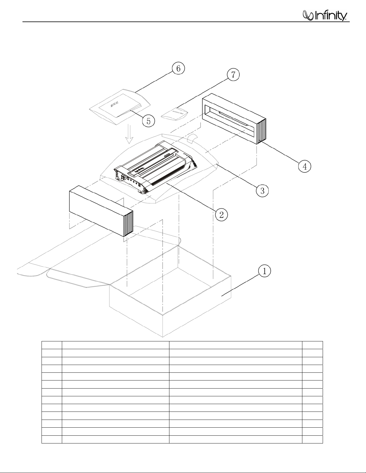
PACKAGING
Item Part Number Description Qty
1 CH4482901201 Outer Carton 1
2 REF1300a REF1300a Amplifier 1
3 Plastic Bag 1
4 BZL279112001 Packing Foam 1
5 Visit Infinitysystems.com Owner's manual 1
6 Plastic Bag 1
7 Accessory kit consisting of: 1
LS1CJ0402507 Mounting Screws 4
1601-203G-00 SPARE 20A FUSES 3
REMOTE REF AMP Remote Level Control 1
2100-0009-04 (RJ11) control cable 1
Page 5
1300a Reference Series
4
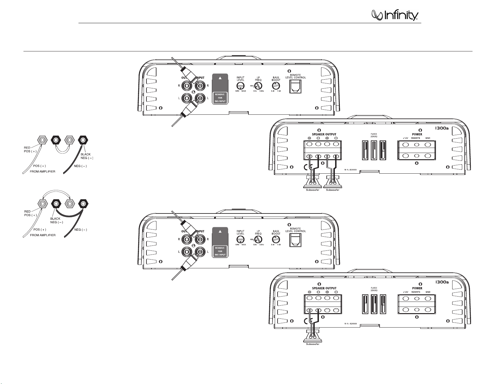
APPLICATIONS – 1300a AND 1600a
The Reference subwoofer amplifiers are
single-channel amplifiers. There are two sets of
terminals to make it easy to connect multiple
woofers. Either set of (+/–) terminals may be
used when connecting woofers.
To the right are four application diagrams to help
plan your subwoofer system installation.
NOTE: For simplicity, Figures 3 and 4 do not
show power, remote and input connections.
Subwoofers or voice coils connected in series.
Figure 3. Reference 1300a or 1600a amplifier with two
woofer connections.
Subwoofers or voice coils connected in parallel.
NOTE: Minimum impedance of each subwoofer = 4 ohms if
subwoofers are connected in parallel and 1 ohm if they
are connected in series.
Figure 4. Reference 1300a or 1600a amplifier with one
woofer connection.
NOTE: Minimum impedance of subwoofer = 2 ohms
3
Page 6
1300a Reference Series
5
INSTALLATION AND SETUP
Refer to the illustrations on the previous pages
for control location.
Reconnect the (–) negative lead to the vehicle’s
battery. Apply power to the audio system and
play a dynamic music track.
SETTING THE CROSSOVER(S)
Determine your system plans and set the
crossover-mode switch accordingly. If your
system design does not include a subwoofer,
set the crossover mode to FULL and skip to
“Setting Input Sensitivity.”
If your system includes a subwoofer, set the
crossover mode to HP (high-pass) for your
full-range speakers. Adjust the crossover
frequency to limit bass, and provide increased
system volume with less distortion.
Mode Switch:
Full: Allows a full-range signal through to the
speakers; can be used with larger full-range
speakers such as 6" x 9"s.
HP: Allows a high-pass signal through to
the speakers; should be used with most
loudspeakers (can protect your full-range
speakers from being overdriven with low
frequencies, one cause of speaker damage).
LP: Allows only bass to pass through to the
speakers; should be selected when powering
subwoofers.
High-Pass Filters: Initially set the crossoverfrequency control midway. While listening
to music, adjust the crossover for the least
perceived distortion from the speakers, allowing
them to reproduce as much bass as possible.
Low-Pass Filters: For subwoofers, choose
the highest frequency that removes vocal
information from the sound of the subwoofer.
If using the 475a to drive a subwoofer(s), set
the crossover mode to LP (low-pass) on the
channels connected to the subwoofer.
NOTE: The 1300a, 1600a and the subwoofer
output of the 5350a are low-pass only and
do not have a crossover-mode switch.
SETTING INPUT SENSITIVITY
1. Initially turn the INPUT LEVEL control(s) to
the minimum (counterclockwise) position.
2. On the source unit, increase the volume
control to 3/4 volume. Slowly increase the
INPUT LEVEL control(s) toward three o’clock
until you hear slight distortion in the music.
Then reduce the INPUT LEVEL slightly until
distortion is no longer heard.
NOTE: After the source unit is on, blue LEDs (on
the top panel) will light, indicating the amplifier
is on. If not, check the wiring, especially the
remote connection from the source unit. Also
refer to “Troubleshooting.”
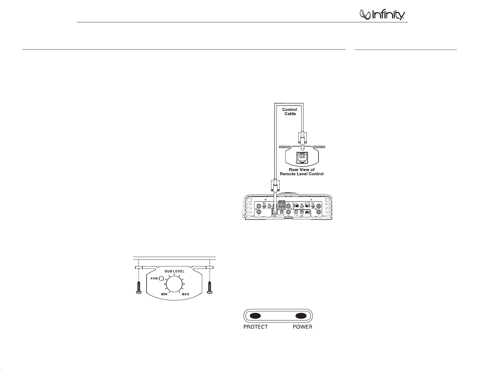
REMOTE LEVEL CONTROL
The 1300a, 1600a and 5350a include a remote
level control. This will allow the subwoofer level
to be adjusted from the listening position.
Connect the remote level control using the
RJ11 jack on the side of the amplifier. Install
the control module in the front of the vehicle
within easy reach of the driver. Both the underside of the dash and the center console are
suitable locations.
UNDER-DASH MOUNTING
Select a mounting location that allows easy
access to the control while driving. Using the
REMOTE LEVEL control as a template, mark and
drill holes in the mounting surface. Attach the
REMOTE LEVEL control using the mounting
screws provided (Figure 11).
Figure 11. Under-dash mounting of the
REMOTE LEVEL control.
Route the cable behind the dash or other
interior panels and under the carpet. Do not
route the cable outside the vehicle. Connect the
RJ11 cable between the RJ11 receptacle on the
amp and the receptacle on the REMOTE LEVEL
control (Figure 12).
Figure 12. REMOTE LEVEL control electrical
connection.
SETTING THE BASS BOOST
The Bass Boost control will allow you to enhance
the bass output of your system at 50Hz up to 6dB.
AUX OUTPUT
Reference amplifiers (except 5350a) are
equipped with full-range outputs that can be
used to connect additional amplifiers.
STATUS LEDs
Power: Indicates the amplifier is on.
Protection: Refer to “Troubleshooting” for specific
indications.
Figure 13. LED status.
TROUBLESHOOTING
• PROBLEM: No audio (POWER LED is off).
CAUSE and SOLUTION: No voltage at BATT+
and/or REM terminals, or bad or no ground
connection. Check voltages at amplifier
terminals with VOM.
• PROBLEM: No audio (PROTECT LED glows red).
CAUSE and SOLUTION: DC voltage on amplifier
output. Amplifier may need service; see
enclosed warranty card for service information.
• PROBLEM: No audio (PROTECT LED glows red).
CAUSE and SOLUTION: Amplifier is overheated.
Make sure amplifier cooling is not blocked at
mounting location; verify that speaker-system
impedance is within specified limits.
• PROBLEM:
No audio (PROTECT LED glows red).
CAUSE and SOLUTION: Voltage less than 9V on
BATT+ connection. Check vehicle charging system.
• PROBLEM: No audio (PROTECT LED glows red).
CAUSE and SOLUTION: Voltage greater than
16V or less than 8.5V on BATT+ connection.
Check vehicle charging system.
• PROBLEM: Distorted audio.
CAUSE and SOLUTION: Input sensitivity is
not set properly, or amplifier or source unit is
defective. Check INPUT LEVEL setting, or check
speaker wires for shorts or grounds.
• PROBLEM: Distorted audio (PROTECT LED glows
intermittently).
CAUSE and SOLUTION: Short circuit in speaker
or wire. Remove speaker leads one at a time to
locate shorted speaker or wire, then repair.
• PROBLEM: Music lacks “punch.”
CAUSE and SOLUTION: Speakers are not
connected properly. Check speaker connections
for proper polarity.
Page 7
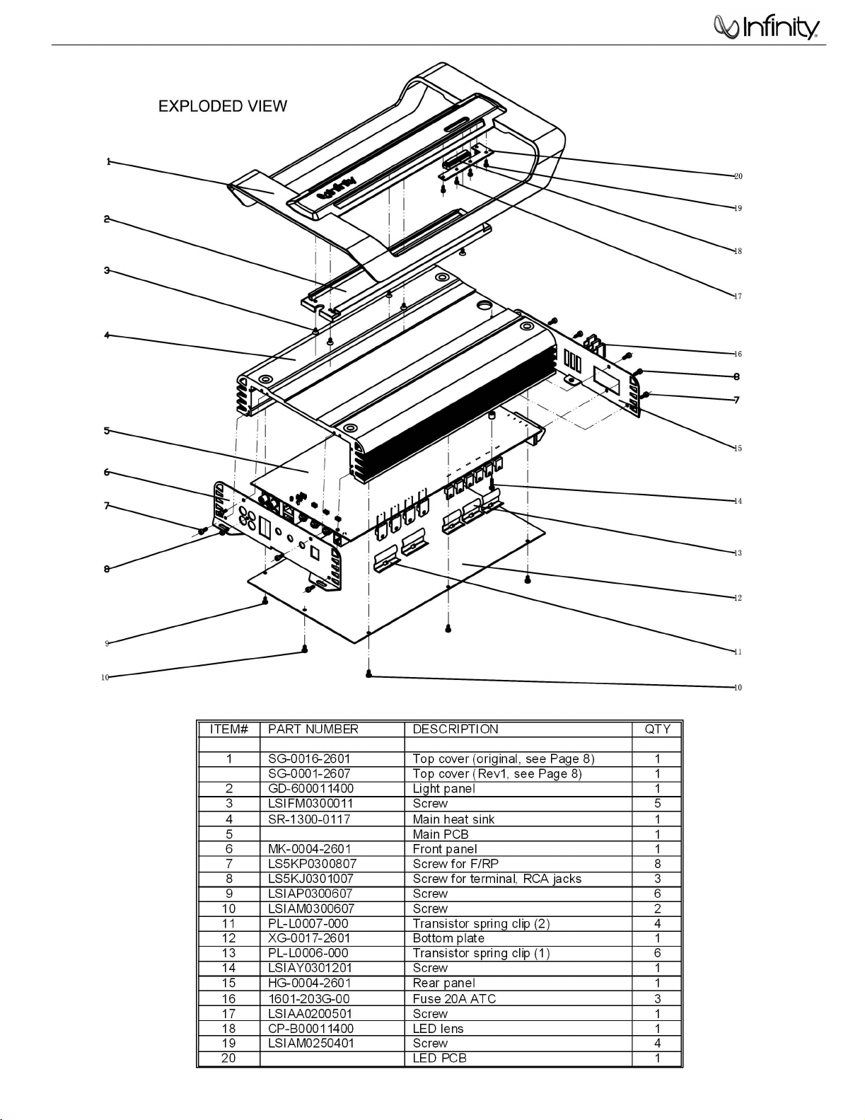
1300a Reference Series
6
Rev0 - Serial number starting with EV0003-
Page 8
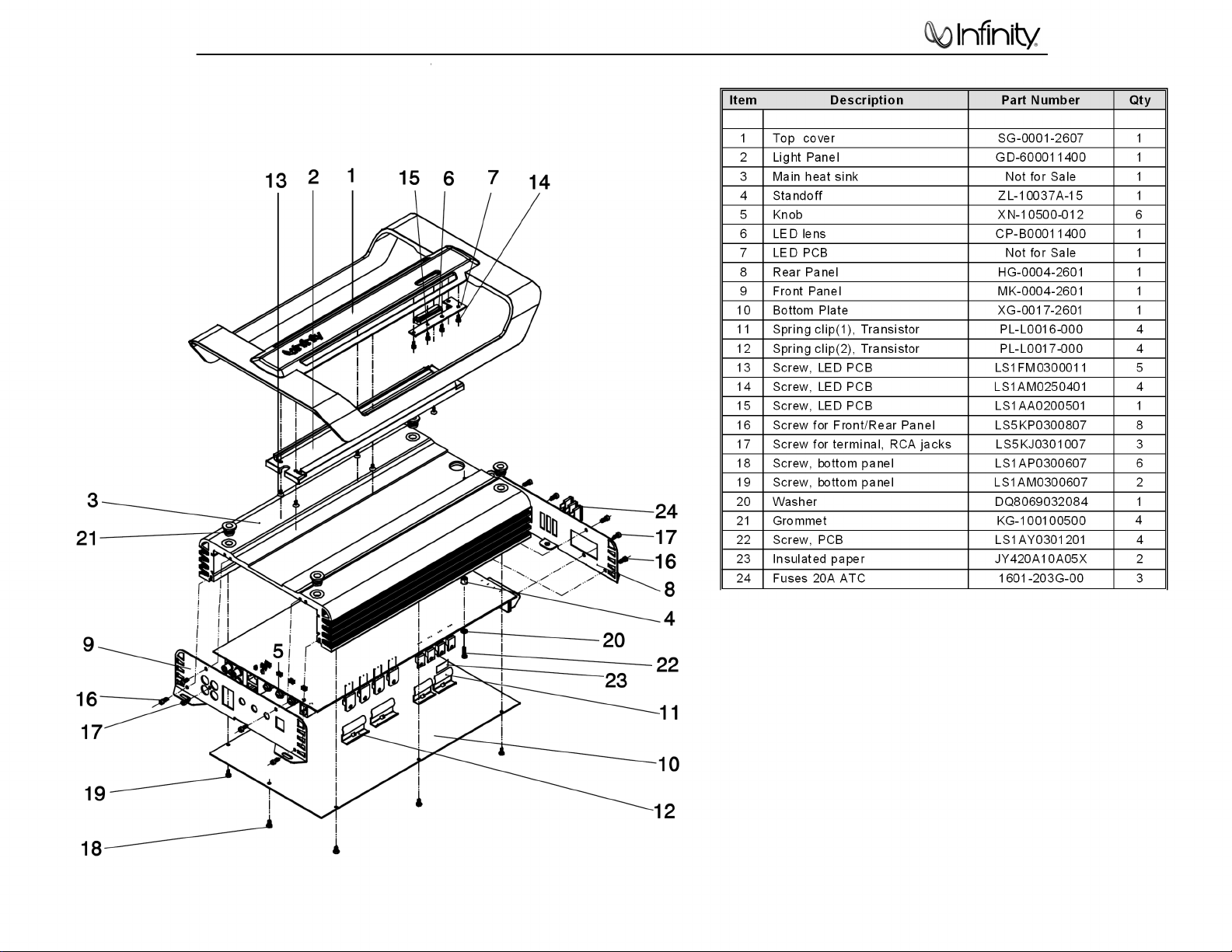
1300a Reference Series
7
Rev1 - Serial number EV0017-01001 and above
Page 9
1300a Reference Series
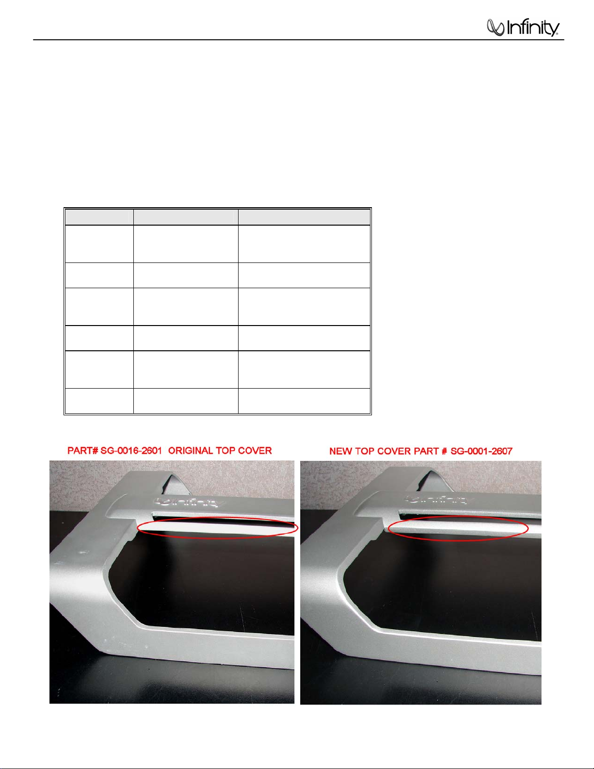
8
NOTE ON TOP COVER FOR INFINITY REFERENCE MODELS REF475A, REF1300A, REF1600A
• There was a revision in the top cover design starting with the serial number range(s) noted below, or
identified by the brace design in the supplied images.
• Note the Rev1 Top cover will not fit properly on the original heatsink.
Top Cover Part Numbers
MODEL PART NUMBER SERIAL NUMBER
EV0001-01000
REF475A
REF475A
REF1300A
REF1300A
REF1600A
REF1600A
SG-0016-2601
SG-0001-2607
SG-0016-2601
SG-0001-2607
SG-0016-2601
SG-0001-2607
to
EV0001-09138
EV0001-09139
And above
EV0003-01000
to
EV0003-08606
EV0003-08607
And above
EV0004-01000
to
EV0004-11811
EV0004-11812
And above
Page 10

1300a Reference Series
9
4321
D
BALANCED
INPUT
UNIT
OP
BALANCED
C
AUX OUT L
INPUT
UNIT
GAIN CONTROL
OP
OP
OP OP
BLOCK DIAGRAM
MODEL FREQ
VARIABLE LP
11HZ--320HZ/12dB
11 25 320 11 32050
BASS BOOST
VARIABLE
0dB--6dB/50HZ
MAIN AMP
FRONTL
AMP
2ohm/4ohm
SPEAKER
B
D
C
B
+15V
+V
AUX OUT R +
OP
Battery
POWER SUPPLY
-
+VCC
-VCC
-V
-15V
A
A
1 2 3 4
Page 11

1300a Reference Series
10
Page 12

1300a Reference Series
11
Page 13

1300a Reference Series
12
REFERENCE 1300a Electrical Parts List
Rev0 - Serial number starting with EV0003-
Part Number Qty Reference Designator
MAIN BOARD
Resistors
0702-10R0-02 Resistor CARBON 1/8W 0Ω ±5% 9 R34 R35 R61 L1 L2 L3 L4 JP140 JP141
0702-34R7-02 Resistor 1/2W 4.7Ω ±5% 3 R242 R36 R37
0702-1220-02 Resistor 1/8W 22Ω ±5% 5 R112 R210 R211 R212 R213
0702-1680-02 Resistor 1/8W 68Ω ±5% 2 R202 R203
0702-1101-02 Resistor 1/8W 100Ω ±5% 7 R42 R132 R133 R134 R136 R137 R138
0702-1221-02 Resistor 1/8W 220Ω ±5% 5 R145 R129 R130 R131 R207
0702-1471-02 Resistor 1/8W 470Ω ±5% 1 R240
1201-1021-03 Variable Resistor 1k Ω 1 RW200
0702-1561-02 Resistor 1/8W 560Ω ±5% 2 R127 R128
0702-1751-02 Resistor 1/8W 750Ω ±5% 1 R38
0702-1102-02 Resistor 1/8W 1KΩ ±5% 10
0702-1152-02 Resistor 1/8W 1.5KΩ ±5% 6 R238 R241 R249 R250 R252 R253
0702-1182-02 Resistor 1/8W 1.8KΩ ±5% 1 R41
0702-1202-02 Resistor 1/8W 2KΩ ±5% 3 R104 R219 R115
0702-1222-02 Resistor 1/8W 2.2KΩ ±5% 4 R124 R217 R218 R204
0702-1332-02 Resistor 1/8W 3.3KΩ ±5% 1 R120
0702-1472-02 Resistor 1/8W 4.7KΩ ±5% 5 R109 R110 R205 R26 R39
0703-1652-03 Resistor 1/8W 6.5KΩ ±1% 1 R106A
0702-1682-02 Resistor 1/8W 6.8KΩ ±5% 5 R159 R157 R214 R215 R216
0702-1752-02 Resistor 1/8W 7.5KΩ ±5% 2 R50 R51
0702-1103-02 Resistor 1/8W 10KΩ ±5% 14
0702-1113-02 Resistor 1/8W 11KΩ ±5% 1 R158
0702-1123-02 Resistor 1/8W 12KΩ ±5% 1 R154
0702-1133-02 Resistor 1/8W 13KΩ ±5% 1 R19
0702-1153-02 Resistor 1/8W 15KΩ ±5% 4 R152 R239 R256 R110A
0702-1203-02 Resistor 1/8W 20KΩ ±5% 3 R17 R18 R119
0702-1223-02 Resistor 1/8W 22KΩ ±5% 8 R106 R108 R147 R208 R1 R2 R7 R109A
0702-1243-02 Resistor 1/8W 24KΩ ±5% 2 R40 R209
0702-1303-02 Resistor 1/8W 30KΩ ±5% 1 R153
0702-1333-02 Resistor 1/8W 33KΩ ±5% 1 R118
0702-1473-02 Resistor 1/8W 47KΩ ±5% 23
0702-1563-02 Resistor 1/8W 56K
0702-1623-02 Resistor 1/8W 62KΩ ±5% 2 R48 R49
0702-1823-02 Resistor 1/8W 82KΩ ±5% 1 R59
0702-1104-02 Resistor 1/8W 100KΩ ±5% 6 D111 R149 R53 R54 R155 R156
0702-1154-02 Resistor 1/8W 150KΩ ±5% 2 R56 R57
0702-1334-02 Resistor 1/8W 330KΩ ±5% 1 R151
0702-1474-02 Resistor 1/8W 470KΩ ±5% 1 R206
0702-1205-02 Resistor 1/8W 2MΩ ±5% 1 R44
0702-3101-02 Resistor 1/2W 100Ω ±5% 2 R222 R223
0702-24R7-02 Resistor 1/4W 4.7Ω ±5% 6 R225 R226 R227 R228 R229 R231
0702-3271-02 Resistor 1/2W 270Ω ±5% 2 R220 R221
0702-2103-02 Resistor 1/4W 10KΩ ±5% 2 R143 R144
0702-2203-02 Resistor 1/4W 20KΩ ±5% 1 R148
0705-515X-07 Cement Resistor 5W 0.15Ω ±5% 6 R233 R234 R236 R237 R259 R260
1204-5031-30 Variable Resistor B50K ±10% LEVEL 1 VR1
1204-1041-07 Variable Resistor B100K ±10% LP FREQ. 1 VR2
Description
R25 R30 R31 R32 R33 R113 R114 R200 R201
R105A
R117 R21 R22 R27 R55 R62 R100 R101 R102
R103 R105 R121 R122 R125
R13 R16 R20 R23 R24 R28 R29 R60 R63
R126 R107 R3 R4 R5 R6 R8 R9 R10 R11 R12
R14 R15 R64
Ω ±5% 3 R150 R58 R235
Page 14

1
1
0
9
2
6
9
0
7
0
1
1
0
0
0
1
0
0
0
1
0
0
0
0
0
0
0
0
0
0
1300a Reference Series
13
Part Number Qty Reference Designator
MAIN BOARD
1204-5041-05 Variable Resistor C500K ±10% BASS BOOST 1 VR3
0704-6202-02 Resistor 2W 2KΩ ±5% 2 R107A R108A
0702-3220-02 Resistor 1/2W 22Ω ±5% 3 R142 R141 R140
0702-1201-02 Resistor 1/8W 200Ω ±5% 1 R45
0702-1562-02 Resistor 1/8W 5.6KΩ ±5% 1 R46
0702-1822-02 Resistor 1/8W 8.2KΩ ±5% 1 R123
Capacitors
Description
06D21224600
06D21225630
06D21226601
06D21476610
06D21476410
06D21107311
06D21227310
06D21477H10
06D21477511
06D21478910
06D21227400
06D21228510
06D23101700
06D23104700
06D23221700
06D23471700
06D23220700
06D23560700
06D23681700
06D23473700
06D32102720
06D32103720
06D32104720
06D21107410
06D32183920
06D34393940
06D32334900
06D34224940
CAP,Electro 0.22UF/50V φ5*11mm ±20% 105℃ 2 C110 C112
CAP,Electro 2.2UF/50V ±20% 5*11 105℃ 1 C208
CAP,Electro 22uF/50V ±20% 5*11 105℃ 12
CAP,Electro 47uF/50V ±20% 5*11 105℃ 2 C35 C36
CAP,Electro 47uF/25V ±20% 5*11 105℃ 2 C139 C102
CAP,Electro 100UF/16V±20% 5*11 105℃ 3 C137 C138 C104
CAP,Electro 220uF/16V ±20% 5*11 105℃ 2 C209 C140
CAP,Electro 470UF/80V ±20% φ16*25mm 2 C135 C136
CAP,Electro 470uF/35V ±20% 10*17 105℃ 2 C133 C134
CAP,Electro 4700UF/63V ±20% φ35*27mm 2 C144 C145
CAP,Electro 220UF/25V ±20% 8*12 105℃ 3 C1 C2 C207
CAP,Electro 2200UF/35V Φ16*26MM ±20% 105℃ 4 C122 C123 C125 C124
Ceramic Capacitor 100pF/100V ±20% 11
Ceramic Capacitor 0.1uF/100V ±20% 28
Ceramic Capacitor 220pF/100V ±20% 1 C38
Ceramic Capacitor 470PF/100V ±20% 1 C37
Ceramic Capacitor 22pF/100V ±20% 2 C42 C44
Ceramic Capacitor 56PF/100V ±20% 2 C201 C202
Ceramic Capacitor 680pF/100V ±20% 2 C200 C203
Ceramic Capacitor 473/100V ±20% 1 C205
Ceramic Capacitor 102/100V ±5% 2 C141 C142
Ceramic Capacitor 103/100V ±5% 2 C126 C127
Ceramic Capacitor 104/100V ±5% 8 C48 C116 C130 C131 C132 C146 C147 C206
CAP,Electro 100uF/25V ±20% 6.3*11 105℃ 2 C148 C143
Ceramic Capacitor 183/63V ±5% 3 C50 C51 C52
Ceramic Capacitor 393/63V ±5% 1 C49
Ceramic Capacitor 334/63V ±5% 2 C46 C47
Ceramic Capacitor 224/63V ±5% 2 C210 C211
C3 C204 C4 C5 C7 C8 C9 C10 C12 C13 C14
C103
C23 C24 C15 C16 C18 C19 C20 C21 C22 C56
C17
C101 C1A C1B C25 C26 C27 C28 C29 C30
C31 C32 C33 C34 C100 C111 C114 C115
C117 C118 C119 C120 C121 C6 C53 C54 C55
C128 C129
Semiconductors
04WY-82AV10 Zener Diode 8.2V DO-35 0.5W 1 DZ100
04ZL-6A10-00 Diode 6A10 1000V 1 D106
04WY-56AV10 Zener Diode 5.6V 0.5W 20MA 52MM DO-35 0.5W 1 DZ101
04PT-4148-04 Diode 1N4148 GSS 200MA 75V DO-35 12
04GS-R104-0
04GS-R204-0
04WY-39AV10 Zener Diode 3.9V DO-35 0.5W 1 DZ101A
03P1-1015-01 Transistor
03P1-A940-02 Transistor 2SA940 PNP TO-220 2 Q218 Q217
Diode FR104 1A 400V 52MM 4 D117 D118 D119 D120
Diode FR204 2A 400V 52MM 4 D107 D108 D109 D110
2SA1015 150MA 60V 400MW PNP
TO-92
D100 D101 D102 D103 D104 D105 D200 D201
D202 D204 D205 D208
5 Q107 Q108 Q109 Q111 Q112
Page 15

1300a Reference Series
14
Part Number Qty Reference Designator
MAIN BOARD
03N1-5551-01 Transistor 2N5551 NPN TO-92 4 Q1 Q210 Q211 Q212
03P1-5401-01 Transistor 2N5401 PNP TO-92 2 Q214 Q215
03P1-1695-13 Transistor 2SA1695 PNP TO-3P 3 Q219 Q220 Q222
03P1-B647-01 Transistor 2SB647 1A 120V 0.9W PNP TO-92 1 Q200
03P1-B649-07 Transistor
03N1-1815-01 Transistor 2SC1815GR 150MA 60V NPN TO-92 11
03N1-2073-02 Transistor 2SC2073 NPN TO-220 3 Q202 Q201 Q213
03N1-4468-13 Transistor 2SC4468 NPN TO-3P 3 Q204 Q205 Q206
03N1-667A-01 Transistor
03N1-8050-01 Transistor S8050 NPN TO-92 1 Q207
01UT-L494-01 IC PWM DIP TL494 DIP16 1 U102
01JR-4560-01 IC DIP NJM4560D Dual Op-amp DIP-8 5 U2 U4 U5 U1 U3
01FA-7815-04 Regulator KA7815E TO-220 FAIRCHILD +15v 1 U100
01FA-7915-04 Regulator KA7915 TO-220 FAIRCHILD -9v 1 U101
2601-P817-00 Optocoupler PC817 DIP4 1 U103
2601-0202-00 Optocoupler LCR-0202 1 R43
03T1-Z48N-02 MOS Transistor IRFZ48N TO-220 6 Q113 Q114 Q115 Q116 Q117 Q118
2202-1602-05 Rectifier UF1602CT AKA 16/200V TO-220 2 D113 D114
2202-1620-05 Rectifier
Description
2SB649A 1.5A 180V 20W PNP TO126
2SD667AC 1A 120V 0.9W NPN TO92
MUR1620CTA KAD 16A/200V TO220
1 Q110
Q122 Q100 Q101 Q102 Q103 Q104 Q105
Q106 Q121 Q208 Q209
1 Q216
2 D115 D116
Miscellaneous
1380-0203-00 Temperature Switch JUC-31F65℃ ±5℃ TO-220 1 RTH1
φ47 4:8:13:18 L1=L2=φ1.0*8*4TS
3000-INIT-02 Transformer
1401-0001-03 Fuse holder DIP 3PIN BXS3-09 1 for F100
1601-203G-00 Fuse DIP 20A/32V 3 F100
1404-0004-00 RCA 4 Jacks white red golden 1 RCA1
1413-0001-00 Phone Jack 6P4C RJ11 Black 1 JK1
1500-0400-01 Terminal JSZ4-32 POWER 1 CN100
1006-1010-10 inductor 100UH 1/2W 1 L11
05RN-3031-02 Thermal resistor 30K Φ5MM 1 RT200
1380-0209-00 Temperature Switch DIP80℃±5℃ TO-220 1 TH100
1500-0300-01 Terminal JSZ3-31 1 CN200
1001-4711-10 inductor
1005-5R03-10 inductor DIP 5UH Φ10*30MM 2 L1A L1B
1400-0001-16 Jack DIP 16PIN RJ45 2* 10P16C 1 CN1
1502-0504-00 Jack
S1=S2=φ1.0*1*8TS
S3=S4=φ1.0*4*13TS
S5=S6=φ1.0*1*18TS
8:8 470UH L1=φ0.6*1*8TS
L2=φ0.6*1*8TS CORE:OR(13*7*5)*2
DIP Pitch 2.0MM 5PIN Bend 90
degree
1 L102
1 L103
1
LED BOARD
2004-0017-00 LBD φ3 white with blue light 8
2100-0036-05 FFC
2000-0017-00 LED DIP Red with red light Φ3MM 2P 1 LED101
2004-0014-00 LED DIP Φ3.0MM Blue with blue light 1 LED100
0701-6102-02 Resistor SMD 1KΩ 1/2W ±5% 2010 2
5PIN 2.0mm UL1007 28AWG
L=225mm
1
Page 16

0
7
7
7
0
4
0
2
J
J
0
0
3
1300a Reference Series
15
Part Number Qty Reference Designator
LED BOARD
Description
2102-0153-02 FFC
2102-0154-02 FFC
1502-0504-00 Jack
06S12104600
04PT-4148-01 Diode SMD 1N4148 DO-213AA 2 D1 D2
SMD Capacitor SMD 0.1uF/50V 0805 X7R ±10% 2 C1 C2
2PIN UL1007 Red Black 28AWG
L=320mm soldering with 5mm
2PIN UL1007 Red Black 28AWG
L=40mm soldering with 5mm
DIP Pitch 2.0MM 5PIN 弯90度
1
1
1
MECHANICAL
S1AM0250401Screw plating black zinc 2.5*4 4
LS1AY0301201Screw PM3*12MM plating black zinc 1
LS1CJ040250
KT-200021300 CAP red PVC RCA jack PVC material 2
KT-200012200 CAP white PVC RCA jack PVC material 2
LS5KP030080
LS5KJ030100
ZL-10037A-15 6.5PC Pole φ7*6.4+φ4.95*1.5mm nylon color 1
ZA-H0004010
DQ806903208
KG-10010050
S1AM0300607Screw PM3*6(plating) 2
LS1AY030045
LS1AA0301501Screw PA3*15(plating black znic) 2
LS1AA0200501Screw PA2*5(plating) 1
S1FM0300011Screw KM 3*6MM black znic 5
LS1FJ0200801 Screw
PL-L0002-000 Grounding GND-3 1
XN-10500-012 Knob ABS-757 black Ф10.5*9MM 3
XN-10500-011 Knob
Y297A22A001Mica 97*22*0.1mm no hole 2
Y247A22A001Mica 47*22*0.1mm no hole 4
CP-B0001140
SG-0016-2601 Top plate
SR-1300-0117 Heatsink 325*216*58mm 1
XG-0017-2601 Bottom Plate
PL-L0007-000 Cliper 30*36*0.8mm 4
PL-L0006-000 Cliper 30*28*0.8mm 6
GD-60001140
GD-60001000
Y222A18A01XMica 22*18*0.1MM 1
HG-0004-2601 Rear Plate
MK-0004-2601 Front Plate
Screw TA4*25MM plating 4 Accessory kit
Screw 3*8MM (plating) 8
Screw 3*10MM (plating) 3
REFsnap button φ7.5 M3.5*4 aluminum 4
Washer Φ6.9*Φ3.2*0.8MM M3 1
snap button
Screw PM3*4.5MM plating white znic 2
Lens
Reflector
Acrylics board 264*48*4.0mm clear Acrylics 1
T07-003-01 snap button φ11*φ14*10.8
black ABS
KA2*8(platiing)
ABS-757black 11.7*Ф11MM red
direction
40*10.8*5.7mm Pc material plastic
grey 10C
360*227*62mm aluminium,H1144silver lacquer silk-screen
325*182*1.2mm H1-144silver
lacquer sick-screen
270*53.5*13mmblue clear PC material
plastic
214*70*1.2mm H1-144silver paint
silk-screen
214*70*1.2mm H1-144silver paint
silk-screen
4
2
1
1
1
1
1
1
1
Page 17

e
1300a Reference Series
16
REFERENCE 1300a Electrical Parts List - Revision 1
Serial number EV0017-01001 and abov
Part Number Description Qty Reference Designator
MAIN BOARD
Resistors
0702-10R0-02 Resistor CARBON 1/8W 0Ω ±5% 9 R34 R35 R61 L1 L2 L3 L4 JP140 JP141
0702-34R7-02 Resistor 1/2W 4.7Ω ±5% 3 R242 R36 R37
0702-1220-02 Resistor 1/8W 22Ω ±5% 5 R112 R210 R211 R212 R213
0702-1680-02 Resistor 1/8W 68Ω ±5% 2 R202 R203
0702-1101-02 Resistor 1/8W 100Ω ±5% 7 R42 R132 R133 R134 R136 R137 R138
0702-1221-02 Resistor 1/8W 220Ω ±5% 5 R145 R129 R130 R131 R207
0702-1471-02 Resistor 1/8W 470Ω ±5% 1 R240
0702-1561-02 Resistor 1/8W 560Ω ±5% 2 R127 R128
0702-1751-02 Resistor 1/8W 750Ω ±5% 1 R38
0702-1102-02 Resistor 1/8W 1KΩ ±5% 10 R25 R30 R31 R32 R33 R113 R114 R200 R201 R105A
0702-1152-02 Resistor 1/8W 1.5KΩ ±5% 6 R238 R241 R249 R250 R252 R253
0702-1182-02 Resistor 1/8W 1.8KΩ ±5% 1 R41
0702-1202-02 Resistor 1/8W 2KΩ ±5% 3 R104 R219 R115
0702-1222-02 Resistor 1/8W 2.2KΩ ±5% 4 R124 R217 R218 R204
0702-1332-02 Resistor 1/8W 3.3KΩ ±5% 1 R120
0702-1472-02 Resistor 1/8W 4.7KΩ ±5% 5 R109 R110 R205 R26 R39
0703-1652-03 Resistor 1/8W 6.5KΩ ±1% 1 R106A
0702-1302-02 Resistor 1/8W 3KΩ ±5% 1 R159
0702-1682-02 Resistor 1/8W 6.8KΩ ±5% 4 R157 R214 R215 R216
0702-1752-02 Resistor 1/8W 7.5KΩ ±5% 2 R50 R51
0702-1103-02 Resistor 1/8W 10KΩ ±5% 14
0702-1113-02 Resistor 1/8W 11KΩ ±5% 1 R158
0702-1123-02 Resistor 1/8W 12KΩ ±5% 1 R154
0702-1133-02 Resistor 1/8W 13KΩ ±5% 1 R19
0702-1153-02 Resistor 1/8W 15KΩ ±5% 4 R152 R239 R256 R110A
0702-1203-02 Resistor 1/8W 20KΩ ±5% 3 R17 R18 R119
0702-1223-02 Resistor 1/8W 22KΩ ±5% 8 R106 R108 R147 R208 R1 R2 R7 R109A
0702-1243-02 Resistor 1/8W 24KΩ ±5% 2 R40 R209
0702-1303-02 Resistor 1/8W 30KΩ ±5% 1 R153
0702-1333-02 Resistor 1/8W 33KΩ ±5% 1 R118
0702-1473-02 Resistor 1/8W 47KΩ ±5% 23
0702-1563-02 Resistor 1/8W 56KΩ ±5% 3 R150 R58 R235
0702-1623-02 Resistor 1/8W 62KΩ ±5% 2 R48 R49
0702-1823-02 Resistor 1/8W 82KΩ ±5% 1 R59
0702-1104-02 Resistor 1/8W 100KΩ ±5% 6 D111 R149 R53 R54 R155 R156
0702-1154-02 Resistor 1/8W 150KΩ ±5% 2 R56 R57
0702-1334-02 Resistor 1/8W 330KΩ ±5% 1 R151
0702-1474-02 Resistor 1/8W 470KΩ ±5% 1 R206
0702-1205-02 Resistor 1/8W 2MΩ ±5% 1 R44
0702-3101-02 Resistor 1/2W 100Ω ±5% 2 R222 R223
0702-24R7-02 Resistor 1/4W 4.7Ω ±5% 6 R225 R226 R227 R228 R229 R231
0702-3271-02 Resistor 1/2W 270Ω ±5% 2 R220 R221
0702-2103-02 Resistor 1/4W 10KΩ ±5% 2 R143 R144
0702-2203-02 Resistor 1/4W 20KΩ ±5% 1 R148
0705-515X-07 Resistor 5W 0.15Ω ±5% 6 R233 R234 R236 R237 R259 R260
0702-3220-02 Resistor 1/2W 22Ω ±5% 3 R142 R141 R140
0702-1201-02 Resistor 1/8W 200Ω ±5% 1 R45
0702-1562-02 Resistor 1/8W 5.6KΩ ±5% 1 R46
R117 R21 R22 R27 R55 R62 R100 R101 R102 R103
R105 R121 R122 R125
R13 R16 R20 R23 R24 R28 R29 R60 R63 R126 R107
R3 R4 R5 R6 R8 R9 R10 R11 R12 R14 R15 R64
Page 18

1300a Reference Series
17
Part Number Description Qty Reference Designator
MAIN BOARD
0702-1822-02 Resistor 1/8W 8.2KΩ ±5% 1 R123
1201-1021-03 Variable Resistor 1k Ω 1 RW200
1204-5031-30 Variable Resistor B50K ±10% LEVEL 1 VR1
1204-1041-07 Variable Resistor B100K ±10% LP FREQ. 1 VR2
1204-5041-05 Variable Resistor C500K ±10% BASS BOOST 1 VR3
0704-6202-02 Resistor 2W 2KΩ ±5% 2 R107A R108A
Capacitors
06D212246001 CAP,Electro 0.22UF/50V 5*11mm ±20% 105℃ 2 C110 C112
06D212256301 CAP,Electro 2.2UF/50V ±20% 5*11 105℃ 1 C208
06D212266010 CAP,Electro 22uF/50V ±20% 5*11 105℃ 12 C3 C204 C4 C5 C7 C8 C9 C10 C12 C13 C14 C103
06D214766109 CAP,Electro 47uF/50V ±20% 5*11 105℃ 2 C35 C36
06D212264103 CAP,Electro 220uF/25V ±20% 8*12 105℃ 1 C104
06D214773101 CAP,Electro 470UF/16V 8*10MM ±20% 105℃ 1 C140
06D211074100 CAP,Electro 100uF/25V ±20% 6.3*11 105℃ 1 C102
06D214764102 CAP,Electro 47uF/25V ±20% 5*11 105℃ 1 C139
06D211073116 CAP,Electro 100UF/16V±20% 5*11 105℃ 2 C137 C138
06D212273109 CAP,Electro 220uF/16V ±20% 5*11 105℃ 1 C209
06D21477H100 CAP,Electro 470UF/80V ±20% φ16*25mm 2 C135 C136
06D214775117 CAP,Electro 470uF/35V ±20% 10*17 105℃ 2 C133 C134
06D214789100 CAP,Electro 4700UF/63V ±20% φ35*27mm 2 C144 C145
06D212274001 CAP,Electro 220UF/25V ±20% 8*12 105℃ 3 C1 C2 C207
06D212285101 CAP,Electro 2200UF/35V Φ16*26MM ±20% 105℃ 4 C122 C123 C125 C124
06D231017000 Ceramic Capacitor 100pF/100V ±20% 11 C23 C24 C15 C16 C18 C19 C20 C21 C22 C56 C17
C101 C1A C1B C25 C26 C27 C28 C29 C30 C31 C32
06D231047000 Ceramic Capacitor 0.1uF/100V ±20% 31
06D232217000 Ceramic Capacitor 220pF/100V ±20% 1 C38
06D234717001 Ceramic Capacitor 470PF/100V ±20% 1 C37
06D232207000 Ceramic Capacitor 22pF/100V ±20% 2 C42 C44
06D235607000 Ceramic Capacitor 56PF/100V ±20% 2 C201 C202
06D236817000 Ceramic Capacitor 680pF/100V ±20% 2 C200 C203
06D234737001 Ceramic Capacitor 473/100V ±20% 1 C205
06D321027200 Ceramic Capacitor 102/100V ±5% 2 C141 C142
06D321037200 Ceramic Capacitor 103/100V ±5% 2 C126 C127
06D321047200 Ceramic Capacitor 104/100V ±5% 8 C48 C116 C130 C131 C132 C146 C147 C206
06D211074100 CAP,Electro 100uF/25V ±20% 6.3*11 105℃ 2 C148 C143
06D321839200 Ceramic Capacitor 183/63V ±5% 3 C50 C51 C52
06D343939400 Ceramic Capacitor 393/63V ±5% 1 C49
06D323349000 Ceramic Capacitor 334/63V ±5% 2 C46 C47
06D342249400 Ceramic Capacitor 224/63V ±5% 2 C210 C211
C33 C34 C100 C111 C114 C115 C117 C118 C119
C120 C121 C6 C53 C54 C55 C128 C129 C151 C152
C153
Semiconductors
04WY-82AV104 Diode 8.2V DO-35 0.5W 1 DZ100
04ZL-6A10-00 Diode 6A10 1000V 1 D106
04WY-56AV104 Diode 5.6V 0.5W 20MA 52MM DO-35 0.5W 1 DZ101
04PT-4148-04 Diode 1N4148 GSS 200MA 75V DO-35 12
04GS-R204-00 Diode FR204 2A 400V 52MM 4 D107 D108 D109 D110
04WY-39AV104 Diode 3.9V DO-35 0.5W 1 DZ101A
03P1-1015-01 Transistor 2SA1015 150MA 60V 400MW PNP TO-92 5 Q107 Q108 Q109 Q111 Q112
03N1-5551-01 Transistor 2N5551 NPN TO-92 4 Q1 Q210 Q211 Q212
D100 D101 D102 D103 D104 D105 D200 D201 D202
D204 D205 D208
Page 19

G
1300a Reference Series
18
Part Number Description Qty Reference Designator
MAIN BOARD
03P1-5401-01 Transistor 2N5401 PNP TO-92 2 Q214 Q215
03P1-B817-13 Transistor KTB817 PNP TO-3P 3 Q219 Q220 Q222
03P1-B647-01 Transistor 2SB647 1A 120V 0.9W PNP TO-92 1 Q200
03P1-B649-07 Transistor 2SB649A 1.5A 180V 20W PNP TO-126 3 Q110 Q217 Q218
03N1-1815-01 Transistor 2SC1815GR 150MA 60V NPN TO-92 11
03N1-669A-07 Transistor 2SD669A NPN TO-126 3 Q202 Q201 Q213
03N1-1047-13 Transistor KTD1047 NPN TO-3P 3 Q204 Q205 Q206
03N1-667A-01 Transistor 2SD667AC 1A 120V 0.9W NPN TO-92 1 Q216
03T1-K30A-01 MOS Transistor 2SK30A TO-92 1 Q207
01UT-L494-01 IC PWM DIP TL494 DIP16 1 U102
01JR-4560-01 IC DIP NJM4560D Dual Op-amp DIP-8 5 U2 U4 U5 U1 U3
01FA-7815-04 Regulator KA7815E TO-220 FAIRCHILD +15v 1 U100
01FA-7915-04 Regulator KA7915 TO-220 FAIRCHILD -15v 1 U101
2601-P817-00 Optocoupler PC817 DIP4 1 U103
2601-0202-00 Optocoupler LCR-0202 1 R43
03D1-50N6-24 MOS Transistor HFP50N06 TO-220 6 Q113 Q114 Q115 Q116 Q117 Q118
2202-1602-05 Dual Rectifier UF1602CT AKA 16/200V TO-220 2 D113
2202-1620-05 Dual Rectifier MUR1620CTA KAD 16A/200V TO-220 2 D115
Q122 Q100 Q101 Q102 Q103 Q104 Q105 Q106 Q121
Q208 Q209
Miscellaneous
3000-GT00-01 Transformer
1401-0001-03 Fuse holder 3PIN BXS3-09 1 for F100
1601-203G-00 Fuse 20A/32V 3 F100
1404-0004-00 RCA 4p 1 RCA1
1413-0001-00 RJ-11 Jack 6P4C RJ11 HPCB-3021-6P4C 1 JK1
1500-0400-01 Terminal JSZ4-32 1 CN100
1006-1010-10 inductor 100UH 1/2W 1 L11
05RN-3031-02 Thermistor 30K Φ5MM 1 RT200
1380-0209-00 Temperature Switch 80℃±5℃ TO-220 1 TH100
1500-0300-01 Terminal JSZ3-31 1 CN200
1005-5R03-10 inductor 5UH Φ10*30MM 1 L1B
Φ40 4:15:8 F1=F2=Φ0.8*12*4TS
S1=S2=Φ0.8*6*15TS S3=S4=Φ0.8*1*8TS
1 L102
LED PCB
3706-0008-02 PCB board PCB board FR-4 thickness=0.8 REV:6.0 1
2004-0017-00 LED φ3 white with blue light 8
2100-0036-05 wire 5PIN 2.0 pitch UL2547#shielded cable 28AW
2000-0017-00 LED DIP red with red light roundΦ3MM 2P 1 LED101
2004-0014-00 LED DIP Φ3.0MM blue with blue light 1 LED100
0701-6102-02 Resistor SMD 1KΩ 1/2W ±5% 2010 2
2102-0153-02 wire 2PIN UL1007 red&black 28AWG L=320mm 1
2102-0154-02 wire 2PIN UL1007 red&black 28AWG L=40mm 1
1502-0504-00 Jack DIP Pitch 2.0MM 5PIN 90bend 1
06S121046000 SMD Capacitor SMD 0.1uF/50V 0805 X7R ±10% 2 C1 C2
04PT-4148-01 Diode SMD 1N4148 DO-213AA 2 D1 D2
1
Page 20

1300a Reference Series
19
Rev0 - Serial number starting with EV0003-
Page 21

1300a Reference Series
20
Page 22

1300a Reference Series
21
321
R46
5K 6
R61
0R
C37
471
RTH1
60
C 23 C C 101
R 62 10K
U2A
N JR 4560
2
3
+15V
84
5
6
NJR 4560
-15V
R39 4K7
C 38 221
R31
1K
Q1
5551
R41
1K 8
R22
10K
U4B
R43 LCR-0202
2
1
+15V
R42
100
R27
10K
R30
1K
1
7
C46
C L 334/MET
C6
C C 104
3
R44
2M
4
R48
62K
C47
C L 334/MET
C24
C C 101
C C 104
2
3
C54
R49
62K
C53
C C 104
C55
C C 104
U4A
NJR 4560
+15V
-15V
C25
C C 104
C26
C C 104
1
C27
C C 104
C28
C C 104
R50
7K 5
4 6
C29
C C 104
C32
C C 104
VR2B
B 100K
5
CROSSOV ER
30H z-320H z
C30
C C 104
C33
C C 104
VR2A
B 100K
R37
4R 7
C31
C C 104
C34
C C 104
2
13
R51
7K 5
C35
47U
R36
4R 7
C36
47U
REM
R 45 200
R26 4K7
+15V
C48
C L 104/MET
6
5
C L 393/MET
C49
C4
W 22U /50V
INPUT
CH1-INPUT
D
C1
NP/220U /25V
L1
0R
INPUT
CH2-INPUT
C2
NP/220U /25V
L2
C
B
0R
RJ45 SU B
RJ45 GND
W 22U /50V
CH1-OUT
CH2-OUT
1
R1
22K
2
C5
W 22U /50VR447K
1 2
C7
W 22U /50V
5
R7
W 22U /50V
W 22U /50V
1 2
3
7
22K
C9
C8
R2
22K
W 22U /50V
W 22U /50V
R53
100K
R54
100K
W 22U /50V
6
1 2
C3
L3
0R
4
8
C12
C13
C14
R3
47K
C15
C C 101
R8
47K
C16
C C 101
R10
47K
C17
C C 101
R14
47K
R9
47K
R32
1K
R33
1K
C18
C C 101
C21
C C 101
C22
C C 101
7
U3B
N JR 4560
U3A
N JR 4560
1
C 19 C C 101
R5
2
3
R6
47K
C20
R 12 47K
6
5
R11
47K
C 56 C C 101
R 64 47K
-15V
6
5
+15V
R15
47K
C 42 C C 22P
47K
R23
-15V
+15V
8 4
R34
0R
R35
0R
R28
47K
C C 22P
C44
U1A
N JR 4560
-15V
N JR 4560
+15V
8 4
U2B
N JR 4560
8 4
R 16 47K
R 20 47K
6
5
3
2
47K
C C 101
U1B
R 24 47K
R 29 47K
R60
47K
47K
R63
1
FR OUT
7
FL OUT
7
R17
20K
R18
20K
R19
13K
R J45 RR
R J45 FR
FR OUT
FL OUT
RJ45 FL
R J45 RL
C10
W 22U /50V
VR1B
B 50K
R38
750R
REM
+15V
R25
1K
R40
24K
5
4 6
R13
47K
R21
10K
Rev0 - Serial number starting with EV0003-
-
+
+V 1
-V1
1
2
3
4
N JR 4560
U5B
1
2
JK1
RJ-11
3
7
R55
10K
R56
150K
C52
C L 183/MET
RJ45 FR
RJ45 FL
R J45 RR
R J45 RL
RJ45 SU B
RJ45 REM
DIAGNOSTIC
RJ45 GND
3
2
C50
C L 183/MET
R58
56K
L4
47U H
+15V
+
-
4 8
-15V
C L 183/MET
BASS BOOST
1 3
R59
82K
CN1
8
7
6
5
5
4
4
3
3
2
2
1
1
RJ45
12
U5A
N JR 4560
1
C51
50H z +6D B
2
VR3A
C 500K
R57
150K
LIN
4
D
C
B
A
DESCRIPTO NREV REV
MV MV1R432022 2007.01.22
1 2 3 4
Place
DATA
DESCRIPTON DATAAPPROVED
LCR-0202 R 43
Place
2007.08.01
PA RT NAM E:
INPUT
PRODUCT MODE:
1300a
SCALE: 1:1
UNIT: MM
SIZE: A4
REV: MV1
DRAW N BY:
CHECKED BY:
A PPRO V E D BY:
JUNPING.LI 2007.08.01
DW GNO:
PA RT NO:
DATA:
DATA:
DATA:
A
Page 23

1300a Reference Series
22
1110987654321
R 109
4.7K
22U /25V
C 103
Q 107
A 1015
R 127
560R
R 128
560R
R 110
4.7K
100U /16V
D 100
1N 4148
C 104
R 112
22R
D 102
1N 4148
Q 111
A 1015
Q 112
A 1015
D 105
1N 4148
C 122
C 101
104
2200U /35V
C 123
2200U /35V
R 129
220R
R 131
220R
R 113
1K
R 118
33K
Q 108
A 1015
R 119
C 124
2200U /35V
R 132
100R
Q 113
IRF48N
Q 114
IRF48N
R 136
100R
C 120
C C 104
20K
C 125
R 120
3.3K
2200U /35V
R 117
C C 104
C1A
IRF48N
IRF48N
10K
C 121
R 133
100R
Q 115
Q 116
R 137
100R
MUTE
-V
L1A
1 2
5U H
C1B
C C 104
C C 104
L1B
1 2
5U H
R 134
100R
Q 117
IRF48N
Q 118
IRF48N
R 138
100R
D 106
6A 10
R 104
2K
L11A
100U H
221
F100A
443
F100B 20 A
F100C 2 0A
C 114
C C 104
R 140
22R / 1/2W
C 126
C L 103
C 127
C L 103
R 141
22R / 1/2W
20A
12
1
3
C 115
C C 104
R 145
220
U 103
P817
C N 100
3
PG ND
3
2
2
REM
1
1
+12V
PO W ER
1
3
2
4
47 4:8:13:18
F47
F1=F2=F1.0*8 4TS
S1=S2=F1.2*1 8TS
S3=S4=F0.8*4 13TS
S5=S6=F0.8*1 18TS
C 102
Q 101
47u/16V
C 1815
R 102
10K
R 103
11
R 108
22K
OP2
10K
C 1815
Q 102
E210E1
9
8
D Z 100
8V 2
C 143
100U /25V
D
C 100
R 100
C C 104
220U /16V
C 140
R 105
10K
R 115
Q 104
C 1815
R 125
10K
T H 10080
2K
10K
R 124
2.2K
R 151
R 153
30K
R 152
15K
D 101
1N 4148
C 110
0.22/50V
R 114
1K
C
Q 109
A 1015
B
+V CC
R 147
22K
R 130
220R
C 139
47U /25V
R 148
20K 0.25W
PO W ER
LED 100
D 111
100K
R 121
10K
0.22U /50V
C 112
R 149
100K
R 107
47K
C 111
C C 104
R 122
10K
Q 105
C1815
DIAGNOSTIC
Q121
C 1815
D Z 101A
3V 9
Q 103
C 1815
R 106A
6K 5
R 123
8K 2
PR O
HI PR O
R 105A
1K
D 103
1N 4148
HI PR O
330K
R 154
12K
D Z 101
5V 6
R 110A
15K
R 155
100K
R 157
6.8K
R 101
10K
16
Q 100
C 1815
R 109A
22K
Q 110
B 649
15
-
+
+1-2FED3DT4C5R6GND7OP1
D 104
R 156
1N 4148
100K
Q 106
C 1815
R 106
22K
R 126
47K
+12
14
REF
T L494C N U 102 T L 494
C 119
C C 104
RED/PR O 5.5M M
13
R 158
LED 101
CON
11K
12
VCC
C 141
C L 102
Rev0 - Serial number starting with EV0003-
RJ45 REM
RJ45 GND
D120
FR 104
D119
FR 104
D117
FR 104
D118
FR 104
D108
FR 204
D107
FR 204
C 128
12L 102
C C 104
C 129
C C 104
R 142
C 142
1 2
470U H
-V
M U R 1620C T
M U R 1620C T
22R / 1/2W
M U R 1620C T R
C L 102
D 113
D 114
D115
5
8
D109
FR 204
10
D110
11
FR 204
6
7
8
9
C 130
C L 104
C 131
C L 104
C 136
470/80V
C 135
470/80V
43L103
C 133
470U /35V
C 134
470U /35V
C 144
C 145
4700U /63V
4700U /63V
C 116
C L 104
C 132
C L 104
U 100 L 7815
1
1
U 101 L7915
Vin
Vin
R 107A
2K /2W
R 108A
2K /2W
R 144
10K 0.25W
R 143
10K 0.25W
V out
GND
2
2
V out
GND
C 146
CL104
C 147
C L 104
C 137
100U /16V
C 138
100U /16V
+V 2
-V2
3
3
+V CC
-VCC
+V 1
C 117
C C 104
C 118
C C 104
-V1
12
D
C
B
RJ45 GND
D116
M U R 1620C T R
A
DESCRIPTO NREV REV
1 2 3 4 5 6 7 8 9 10 11 12
Place
DATA
DESCRIPTON DATAAPPROVED
Place
PA RT NAM E:
PO W ER
PRODUCT MODE:
1300a
SCALE: 1:1
UNIT: MM
SIZE: A4
REV: MV1
DRAW N BY:
CHECKED BY:
APPROVED BY :
JUNPING.LI 2007.08.01
DW GNO:
PA RT NO:
DATA:
DATA:
DATA:
A
Page 24

1300a Reference Series
23
321
4
Rev0 - Serial number starting with EV0003-
+V 2
R 202
D
MUTE
R 207
220R
R 206
470K
Q207
S8050
R 205
4.7K
C 204
W 22U /50V
R 208
22K
C 205
C C 473
R 204
2K 2
LIN
C
B
R 200
1K
R 210
R 212
22R
Q 211
5551
22R
Q 214
5401
-V1
+V 1
Q 212
5551
R 211
22R
R 214
6.8K
R 216
6.8K
R 213
22R
Q 215
5401
C 201
C C 56P/100V
CC56P/100V
C 202
D 200
4148
D 201
4148
R 217
2.2K
R 218
2.2K
RW 200
1K
Q 200
B 647
68R
R 219
2K
R T 200
30K
Q 216
D 667
C 200
C C 681/100V
Q 213
C 2073
R 240
470R
C 209
220U /16V
R 220
270R 0.25W
C 206
C L 104
R 209
24K
R 221
270R 0.25W
Q 201
C 2073
Q 217
A 940
Q 202
C 2073
R 227
4.7R 0.25W
R 222
100/0.5W
R 223
100/0.5W
R 228
4.7R 0.25W
Q 218
A 940
R 236
0.15R /5W
R 259
0.15R /5W
Q 219
A 1695
Q 206
C 4468
R 225
4.7R 0.25W
R 238
1K 5
R 252
1K 5
R 229
4.7R 0.25W
R 249
1K 5
R 253
1K 5
Q 220
A 1695
Q 204
C 4468
R 233
0.15R /5W
R 260
0.15R /5W
4.7R 0.25W
R 226
4.7R 0.25W
R 231
R 234
0.15R /5W
R 237
0.15R /5W
Q 222
A 1695
Q 205
C 4468
R 250
1K 5
R 241
1K 5
C 148
100U /25V
R 150
56K
R 159
6K 8
+V CC
Q122
C 1815
N P 220U /26V
R 235
56K
C 207
Q208
C 1815
R 215
6.8K
R 256
15K
D205
4148
D 202
4148
Q209
C 1815
C 208
2.2U /50V
R 239
15K
D208
4148
D204
4148
Q210
5551
C 211
C L 224
C 210
C L 224
R 242
4.7R 0.5W
PR O
C N 200
1
2
3
4
D
C
B
R 201
1K
A
1 2 3 4
-V2
R 203
68R
C 203
C C 681/100V
DESCRIPTO NREV REV
Place
DATA
-VCC
DESCRIPTON DATAAPPROVED
Place
PA RT NAM E:
AM P
PRODUCT MODE:
1300a
SCALE: 1:1
UNIT: MM
SIZE: A4
REV: MV1
DRAW N BY:
CHECKED BY:
A PPRO V E D BY:
DW GNO:
PA RT NO:
JUNPING.LI 2007.08.01
DATA:
DATA:
DATA:
A
Page 25

1300a Reference Series
24
7654321
8
Rev1 - Serial number EV0017-01001 and above
R145
RJ45 REM
220
20A
C115
CC104
3
2
12
1
1
3
1
3
2
4
47 4:8:13:18
F1=F2=F1.0*8 4TS
S1=S2=F1.2*1 8TS
S3=S4=F0.8*4 13TS
S5=S6=F0.8*1 18TS
U103
P817
CN100
PGND
3
REM
2
+12V
1
POWER
F47
RJ45 GND
FR104
FR104
D117
FR104
D118
FR104
D108
FR204
FR204
12L102
5
8
10
11
6
7
8
9
D120
D119
D107
D109
FR204
D110
FR204
C128
CC104
C129
CC104
R142
C142
22R/ 1/2W
CL102
C130
CL104
1 2
470UH
-V
D113
MUR1620CT
D114
MUR1620CT
D115
MUR1620CTR
C131
CL104
43 L103
470/80V
C135
470/80V
C136
C133
470U/35V
C134
470U/35V
C144
4700U/63V
C145
4700U/63V
1
1
L1A
5UH
IRF48N
IRF48N
R104
2K
L11A
100UH
221
F100A
D106
443
6A10
F100B 20A
F100C 20A
C114
CC104
R134
100R
Q117
Q118
R138
100R
R140
22R/ 1/2W
C126
CL103
C127
CL103
R141
22R/ 1/2W
C116
CL104
10K0.25W
C132
10K0.25W
CL104
U100 L7815
Vin
GND
2
2
Vin
GND
U101 L7915
R107A
2K/2W
R108A
2K/2W
D
+V2
R144
R143
Vout
Vout
C146
CL104
C147
CL104
C137
100U/16V
C138
100U/16V
-V2
3
3
+VCC
-VCC
+V1
C117
CC104
C118
CC104
-V1
C
B
R109
4.7K
C103
22U/25V
Q107
A1015
R127
560R
R128
560R
R110
4.7K
D100
1N4148
C104
220U/25V
R112
22R
D102
1N4148
Q111
A1015
Q112
A1015
D105
1N4148
C101
104
C122
2200U/35V
C123
2200U/35V
R129
220R
R131
220R
R113
1K
R118
33K
Q108
A1015
C124
2200U/35V
R132
100R
Q113
IRF48N
Q114
IRF48N
R136
100R
C120
CC104
R120
3.3K
MUTE
R119
20K
C125
2200U/35V
R117
C121
CC104
C1A
IRF48N
IRF48N
10K
R133
100R
Q115
Q116
R137
100R
CC104
-V
1 2
C1B
CC104
L1B
1 2
5UH
C102
Q101
100U/25V
C1815
D
R106
22K
C100
R100
CC104
C140
470U/16V
10K
Q104
DZ101
C1815
5V6
R125
R110A
10K
15K
R124
2.2K
R151
330K
R105
R154
10K
12K
R155
100K
TH10080
R157
R153
30K
6.8K
R115
2K
R152
15K
D101
1N4148
C110
R107
DZ101A
0.22/50V
C
Q109
A1015
B
+VCC
R147
22K
R130
220R
C139
47U/25V
R148
20K0.25W
POWER
LED100
D111
100K
R121
10K
R114
1K
C112
0.22U/50V
R149
100K
47K
C111
CC104
R122
10K
Q105
C1815
DIAGNOSTIC
Q121
C1815
3V9
Q103
C1815
R106A
6K5
R123
8K2
HI PRO
HI PRO
R105A
1K
PRO
D103
1N4148
Q100
R101
C1815
10K
R109A
22K
R126
Q110
47K
B649
14
15
-
REF
TL494CN U102 TL494
R156
100K
Q106
C119
C1815
CC104
LED101
RED/PRO5.5MM
13
CON
R158
11K
CL102
16
+
+1-2FED3DT4C5R6GND7OP1
D104
1N4148
R102
10K
R103
10K
C1815
Q102
DZ100
8V2
+12
11
12
VCC
R108
C141
9
E210E1
OP2
8
C143
100U/25V
22K
RJ45 GND
D116
A
ECN NO
1 2 3 4 5 6 78
DESCRIPTON
DATAAPPROVED
PART NAME:
POWER
PRODUCT MODE:
infinity REF-1300a
MUR1620CTR
SCALE: 1:1
UNIT: MM
SIZE: A4
REV: 2.0
DRAWN BY:
JUNPING.LI 2008.06.23
CHECKED BY:
APPROVED BY:
DW GNO:
PART NO:
DATA:
DATA:
DATA:
A
Page 26

1300a Reference Series
25
7654321
Rev1 - Serial number EV0017-01001 and above
8
D
R200
1K
C201
CC56P/100V
MUTE
Q207
2SK30A
R205
4.7K
R207
220R
R206
470K
C204
W22U/50V
R208
C205
CC473
22K
R212
R201
R210
Q211
Q212
5551
5551
R211
22R
22R
R214
6.8K
-V1
+V1
R216
6.8K
R213
22R
22R
Q214
Q215
5401
5401
CC56P/100V
1K
R204
2K2
LIN
C
B
C202
D200
4148
D201
4148
R217
2.2K
R218
2.2K
RW200
+V2
R202
C200
68R
CC681/100V
Q200
B647
R219
2K
RT200
30K
Q213
C2073
1K
R240
470R
220U/16V
Q216
D667
R203
C203
68R
CC681/100V
C209
R220
270R0.25W
C206
CL104
R209
24K
R221
270R0.25W
Q201
C2073
Q217
A940
Q202
C2073
R227
4.7R0.25W
R222
100/0.5W
R223
100/0.5W
R228
4.7R0.25W
Q218
A940
R236
0.15R/5W
0.15R/5W
R259
A1695
Q219
Q206
C4468
R225
4.7R0.25W
R238
1K5
R252
1K5
R229
4.7R0.25W
R249
R253
1K5
1K5
A1695
Q220
Q204
C4468
R233
0.15R/5W
0.15R/5W
R226
4.7R0.25W
R260
R231
4.7R0.25W
R234
0.15R/5W
R237
0.15R/5W
Q222
A1695
Q205
C4468
R241
1K5
R250
1K5
C148
100U/25V
R150
56K
R159
+VCC
C208
2.2U/50V
R239
D208
4148
D204
4148
Q210
5551
C211
CL224
C210
CL224
R242
4.7R0.5W
15K
PRO
CN200
1
2
3
4
D202
4148
C207
NP220U/26V
R235
56K
R215
6.8K
Q208
C1815
R256
15K
D205
4148
Q209
C1815
Q122
3K
C1815
D
C
B
-V2
A
ECN NO DESCRIPTON DATAAPPROVED
1 2 3 4 5 6 78
-VCC
PART NAME:
AMP
PRODUCT MODE:
infinity REF-1300a
SCALE: 1:1
UNIT: MM
SIZE: A4
REV: 2.0
DRAWN BY:
JUNPING.LI 2008.06.23
CHECKED BY:
APPROVED BY:
DW GNO:
PART NO:
DATA:
DATA:
DATA:
A
Page 27

D
26
C
B
A
INPUT
CH1-INPUT
C1
NP/220U/25V
L1
0R
INPUT
CH2-INPUT
C2
NP/220U/25V
L2
0R
RJ45 SUB
RJ45 GND
CH1-OUT
CH2-OUT
1300a Reference Series
8
7
6
5
4
3
2
1
12
C51
VR3A
C500K
6
CN1
D
5
4
3
2
1
RJ45
C
B
1
LIN
R57
150K
2
A
DW GNO:
PART NO:
DATA:
DATA:
DATA:
54321
R21
10K
R13
47K
R46
5K6
C37
471
RTH1
60
R61
0R
C23 CC101
R62 10K
2
NJR4560
3
+15V
84
5
6
R39 4K7
C38 221
R31
1K
Q1
5551
R41
1K8
℃
U2A
U4B
NJR4560
-15V
2
1
+15V
R22
10K
R42
100
R27
10K
R30
1K
1
7
R43 2022
CL334/MET
Rev1 - Serial number EV0017-01001 and above
+15V
C29
C25
CC104
C26
CC104
1
C27
CC104
C28
CC104
R50
7K5
4 6
DESCRIPTON
VR2B
B100K
CROSSOVER
30Hz-320Hz
C6
CC104
3
4
R48
62K
C46
C47
CL334/MET
C24
CC101
C53
CC104
-15V
C55
C54
CC104
CC104
R44
2M
U4A
2
NJR4560
3
R49
62K
ECN NO
CC104
C32
CC104
5
C30
CC104
C33
CC104
VR2A
B100K
2
C31
CC104
C34
CC104
R37
4R7
+V1
C35
47U
R36
4R7
-V1
C36
47U
1
REM
R45 200
R26 4K7
+15V
C48
CL104/MET
6
R51
7K5
13
5
CL393/MET
1
2
2
JK1
RJ-11
3
3
4
U5B
NJR4560
7
+
C49
R55
10K
R56
150K
C52
CL183/MET
RJ45 FR
RJ45 FL
RJ45 RR
RJ45 RL
RJ45 SUB
RJ45 REM
DIAGNOSTIC
RJ45 GND
3
2
C50
CL183/MET
R58
56K
L4
47UH
+15V
U5A
NJR4560
+
-
4 8
-15V
CL183/MET
BASS BOOST
50Hz +6DB
1 3
R59
82K
DATAAPPROVED
PART NAME:
SING
PRODUCT MODE:
infinity REF-1300a
SCALE: 1:1
UNIT: MM
SIZE: A4
REV: 3.0
DRAWN BY:
JUNPING.LI 2008.06.23
CHECKED BY:
APPROVED BY:
C4
C5
C7
R7
22K
C9
C8
R2
22K
C12
W22U/50V
C13
W22U/50V
C14
W22U/50V
C15
CC101
CC101
C17
CC101
R3
47K
R8
47K
C16
R10
47K
47K
R14
47K
R32
R33
R9
1K
1K
W22U/50V
1
R1
22K
2
W22U/50VR447K
1 2
W22U/50V
5
6
W22U/50V
1 2
W22U/50V
C3
W22U/50V
L3
0R
1 2
3
4
R53
100K
R54
100K
8
7
1 2 3 4 56
C18
CC101
C21
CC101
C22
CC101
7
U3B
NJR4560
U3A
NJR4560
1
C19 CC101
R5
2
3
R6
47K
C20
R12 47K
6
5
R11
47K
C56 CC101
R64 47K
-15V
6
5
+15V
R15
47K
C42 CC22P
47K
R23
-15V
+15V
8 4
R34
0R
R35
0R
R28
47K
CC22P
C44
NJR4560
NJR4560
8 4
NJR4560
8 4
6
5
3
2
47K
U1A
CC101
-15V
U1B
+15V
U2B
R16 47K
R20 4 7K
R24 47K
R29 47K
R60
47K
R63
1
FR OUT
7
FL OUT
7
47K
R17
20K
R18
20K
R19
13K
RJ45 RR
RJ45 FR
FR OUT
FL OUT
RJ45 FL
RJ45 RL
C10
W22U/50V
VR1B
B50K
R38
750R
REM
+15V
5
4 6
R25
1K
R40
24K
Page 28

27
Service bulletin # INF2008-02 April 2008
To: All Infinity Service Centers
Model: Reference 1300A
Subject: Turn On/Off Popping Sound
In the event you receive a Reference 1300A auto amplifier with the complaint: “There is a popping
sound in the speakers when the unit turns on or off”, perform the following modification.
Synopsis: Change three components with new component values, and one Transistor with another type.
Note: RoHS-rated* de-soldering and soldering equipment will be required.
1) Remove the silver trim panel (see the owner’s manual page 2); unplug the five-pin Molex connector.
2) Remove the bottom cover, (8) Phillips screws.
3) Remove the front & rear side panels, 2.5mm Allen (hex key) screws.
4) Remove all nine steel transistor clamps. The technique is detailed in Infinity Tech Tip #INFTT2008-01.
5) Slide the main PCB out of the heatsink. Locate and replace the following components.
6) Order kit # REF1300Akit2008, which should contain the following components:
C102, 47µf/16V Electrolytic cap; replace with new 100µf/25V cap
C104, 100/16V Electrolytic cap; replace with new 220µf/25V cap
C140, 220µf/16V Electrolytic caps; replace with new 470u/16V cap
Q207 Transistor 2SC8050 NPN TO-92, replace with new 2SK30A JFET TO-92
When replacing capacitors, observe polarity.
(New transistor should be inserted exactly the same way as former one.)
7) Replace main PCB, clamps, Molex connectors, front & rear panels, and bottom cover.
8) Test unit to assure the complaint has been resolved.
Warranty labor rate: MAJOR repair
Service Bulletin
Model Serial Number STATUS ACTION
EV0003-01001
Reference 1300A
Reference 1300A
* RoHS = Restriction Of Hazardous Substances. Recommended lead free solder 96.5/3.0/0.5 LICK HERE
to
EV0003-09654
EV0003-09655
and above
May need component replacement
due to popping noise
Modified by Factory NONE REQUIRED
Replace four components
Page 29
1300a Reference Series
28
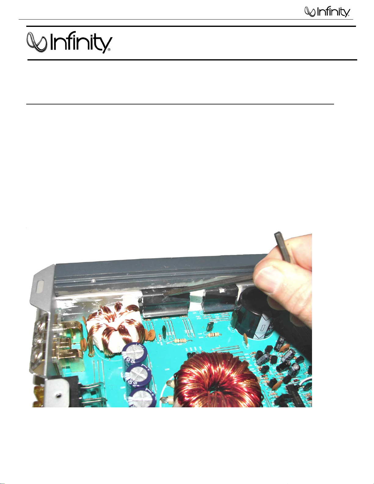
TECH TIPS
For models: Reference Series 475a,1300a,1600a,5350a TIP# INFTT2008-01
Subject:
How do you remove the heatsink clips on the Reference Series amplifiers to service the main PCB
or replace an output device ?
Solution:
The heatsink clips on the Reference Series may be extracted from the heatsink channel by the
use of a hardened steel tool such as a 9/64” allen (hex key) wrench, and inserting it into the
square hole in the middle of the clip. Enter the hole and press the tool downwards, concentrating
on first one side of the clip; then switch to the other side. The clip should creep out of the slot in
the heatsink. Sometimes a substantial amount of force may be required before it comes out with a
“pop”. To replace, the clip must be hammered back into place, back into the groove, with a
hammer and extension bar, if needed.
Troubleshooting tips and solutions to common service problems
Infinity Systems, Inc. 250 Crossways Park Dr. Woodbury, New York 11797
 Loading...