

Page 1

Reference Series
1210a
1211a
1 CHANNEL POWER AMPLIFIER
SERVICE MANUAL
Infinity Systems, Inc.
250 Crossways Park Dr.
Woodbury, New York 11797 Rev
2aa10/2005
Page 2

Power Amplifier Reference 1210a/1211a
1
- CONTENTS -
SPECIFICATIONS ………………………………….……..1
FEATURES/TEST CONDITIONS……..…………………2
CONTROLS/CONNECTIONS………….……..…...…..…3
INSTALLATION………………….……...……..…...…...…5
BASIC TROUBLESHOOTING..…….…….………………7
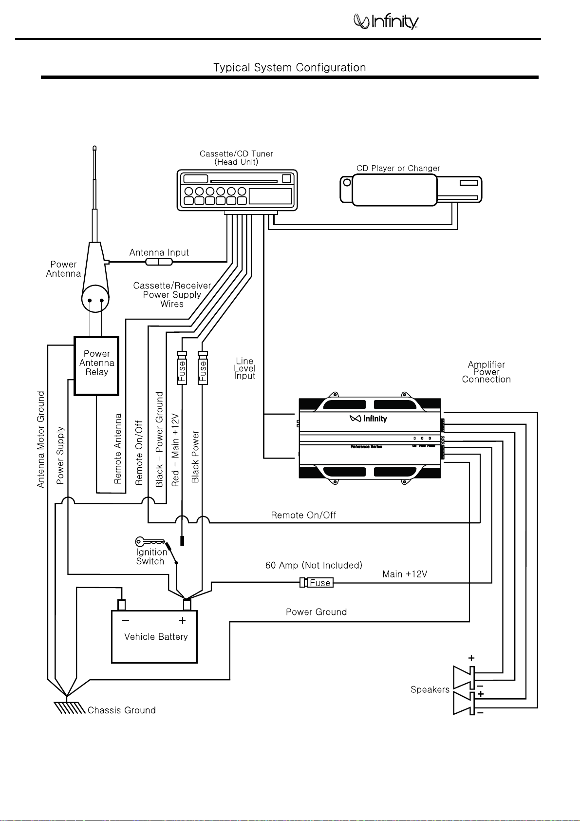
TYPICAL SYSTEM WIRING..…….…….……………..…8
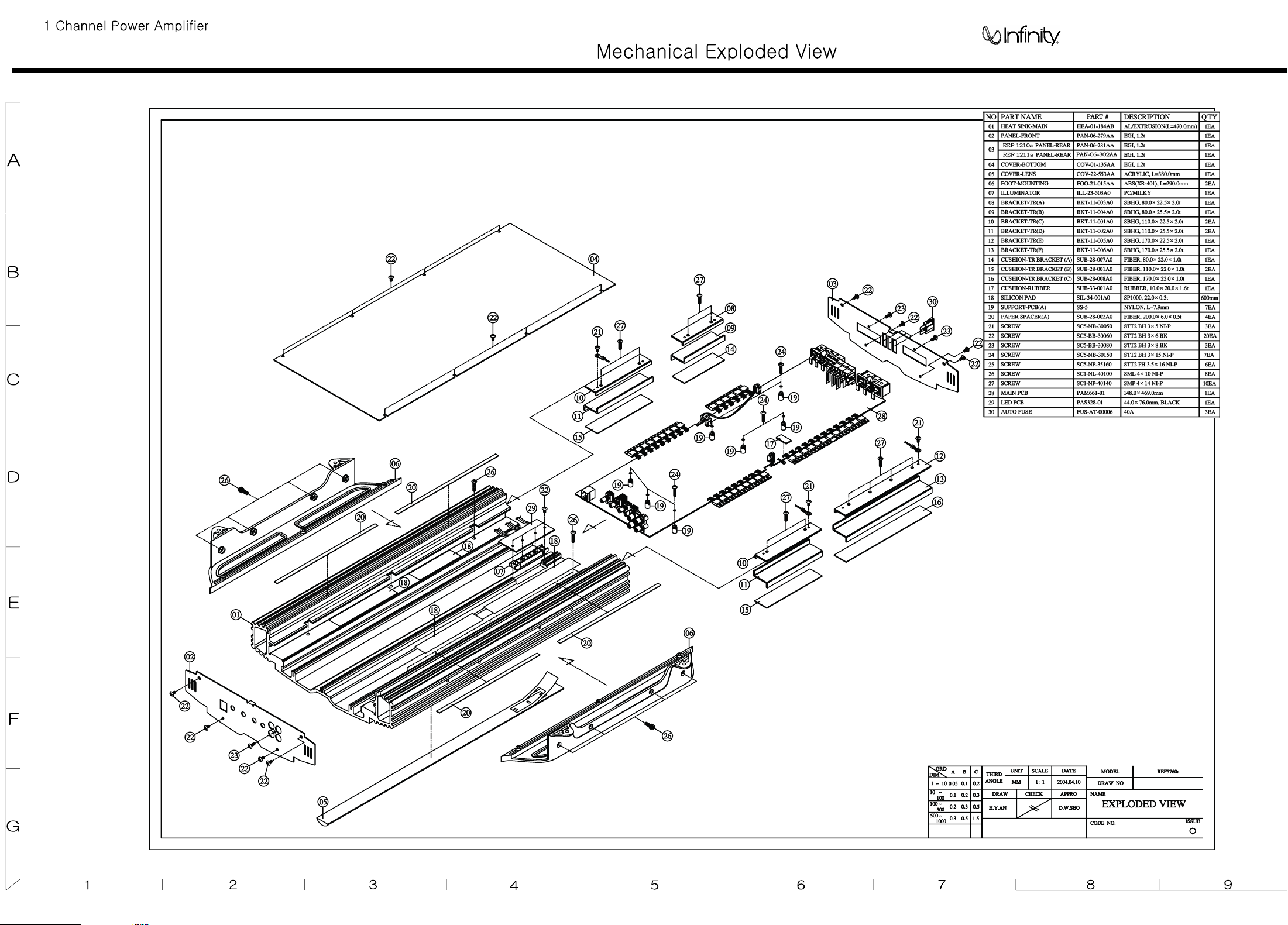
EXPLODED VIEW/PARTS LIST………………………....9
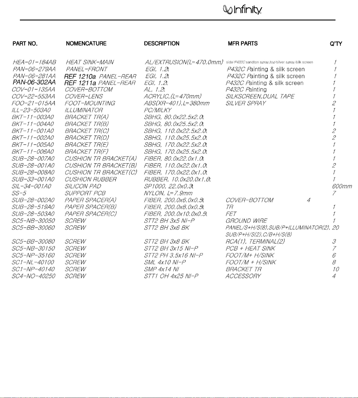
MECHANICAL PARTS LIST…………………………….10
AMPLIFIER BLOCK DIAGRAM…………………………11
P.C.B. DRAWINGS….…………………………………….12
ELECTRICAL PARTS LIST ……………………………. 16
REF 1211a ELECTRICAL PARTS LIST ADDENDUM…...…20
IC/TRANSISTOR PINOUTS..…………………………….21
REF 1210a SCHEMATICS………..…………..……..…..27
REF 1211a SCHEMATICS………..……………………..30
PACKING……………………….…………………………33
Reference 1210a/1211a Specifications
Output Power: 854W RMS x 1 @ 4 ohms; ≤1% THD + N
(14.4 VDC) 1300W RMS x 1 @ 2 ohms; ≤1% THD + N
Signal-to-noise ratio: 72dBA (reference 1W into 4 ohms)
Dynamic power: 1516W channels @ 2 ohms
Effective damping factor: 6.357 @ 4 ohms
Frequency response: 17Hz – 302Hz (-3dB)
Maximum input signal: 5.7V
Maximum sensitivity: Reference 1210a - 260mV
Reference 1211a - 75mV
DC Offset <50mV (-50%)
Output regulation: .132dB @ 4 ohms
Idle Current 2.8A
Input Impedance 22kΩ
Max Current Draw 70A @ 4 ohms
125A @ 2 ohms
Dimensions: 12 x 18 1/2 x 2 11/16” (L x W x D)
(305mm x 470mm x 68mm)
Fuse: 3 x 40A
Infinity continually strives to update and improve existing products, as well as create new ones. The specifications and details in
this and related JBL publications are therefore subject to change without notice.
Page 3

Power Amplifier Reference 1210a/1211a
2
Features
x 1-Channel Operation
x Advanced MOSFET Oversized Floating Rail Power Supply
x Floating Ground Factory
x Variable lnput Sensitivity (250mV
x Fully Complementary Output Stage with Class-D Voltage Amplification
x Gold-plated Power, lnput and Output Connectors
x 2-Ohm Stable
- Head - Unit Speaker - Level input
- 6V)
Test Conditions and Notes
x All tests to be done, unless otherwise specified, from 10Hz to 302Hz at 14.4V DC
into 2 ohm loads and adjust the units gain so that with a .250 volt input signal the
unit is at Its maximum rated output. All measurements will be done using an
Audio precision system one and the supply voltage.
x An A+ line voltage of 14.4V DC shall be applied to the unit under test for all
measurements unless otherwise specified. The voltage applied to the unit shall
be measured at the power connection on the Amplifier.
x Signal Source
Unless otherwise specified, all tests shall be conducted with the Audio Signal
Generator output configured to be balanced, less than or equal to 50 ohm source
impedance, and floating. The signal source "GND" shall be connected to the
Amplifier PWR GND at the Amplifier.
x Output Load
Unless otherwise specified, all tests shall be conducted with 2 ohm resistive
loads having less than 10% reactive components at any frequency below 302Hz.
Each resistor shall have a value that remains within 1
rated output of the unit under test.
x Power Indicator Green LED steadily illuminates for normal operation. Illuminates
up Red LED blinks when protection circuitry is engaged, and during power up.
% while dissipating the
Page 4
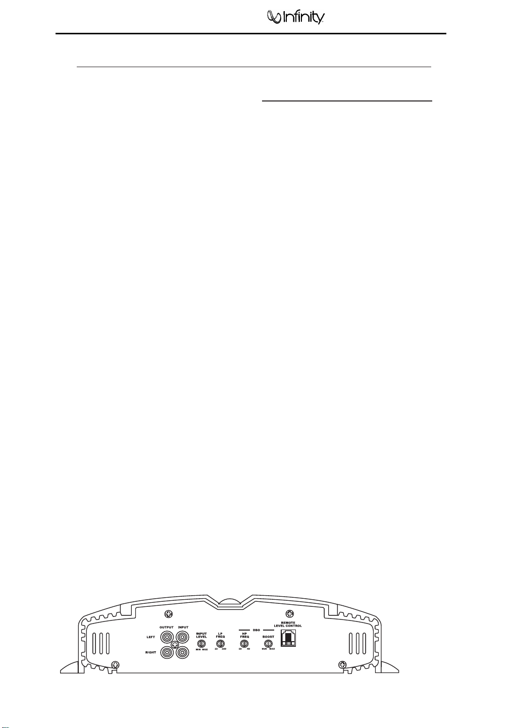
The Reference amplifiers are capable of
delivering high power levels, and require a
reliable connection to the vehicle’s electrical
system in order to perform optimally. See
Figure 1 for connection location. Please
adhere to the following instructions carefully.
GROUND CONNECTION
Connect the amplifier’s Ground (GND) terminal
to a solid point on the vehicle’s metal chassis,
as close to the amplifier as possible. Refer to the
chart below to determine minimum wire-gauge
size. Sand away any paint from this location; use
a star-type-lock washer to secure the connection.
POWER CONNECTION
Connect a wire (see chart at right for appropriate
gauge) directly to the vehicle’s positive battery
terminal, and install an appropriate fuse holder
within 18" of the battery terminal. Do not
install the fuse at this time. Route the wire to
the amplifier’s location, and connect it to the
amplifier’s positive (+12V) terminal. Be sure to
use appropriate grommets whenever routing
wires through the firewall or other sheet metal.
Failure to adequately protect the positive wire
from potential damage may result in a vehicle
fire. When you are done routing and connecting
this wire to the battery and to the amplifier,
you may install the fuse at the battery. The
fuse value should be selected based on total
amplifier-current draw; see chart at right.
REMOTE CONNECTION
Connect the amplifier’s Remote (REMOTE)
terminal to the source unit’s Remote Turn-On
lead using a minimum of 18-gauge wire. If your
source unit does not have a remote turn-on
connection, connect the amplifier’s (REMOTE)
terminal to the vehicle’s accessory circuit.
SPEAKER CONNECTIONS
Refer to the application guides on the pages
that follow. Speaker connections should be
made using a minimum of 16-gauge wire.
NOTE: When using the low-level or high-level
inputs, the AUX outputs can be used to pass a
full-range line-level signal to another amplifier.
POWER CONNECTIONS
Figur
e 1
.
T
erminal-connection end plate.
Power Amplifier Reference 1210a/1211a
3
WIRE-GAUGE CHART
Amplifier Maximum Minimum
Model Current Draw Wire Gauge
AWG
AWG
1210a/1211a 115A #4 AWG
These recommendations assume 7' – 10' wire
runs. If your installation differs markedly, you
will need to adjust the wire gauge accordingly.
Page 5
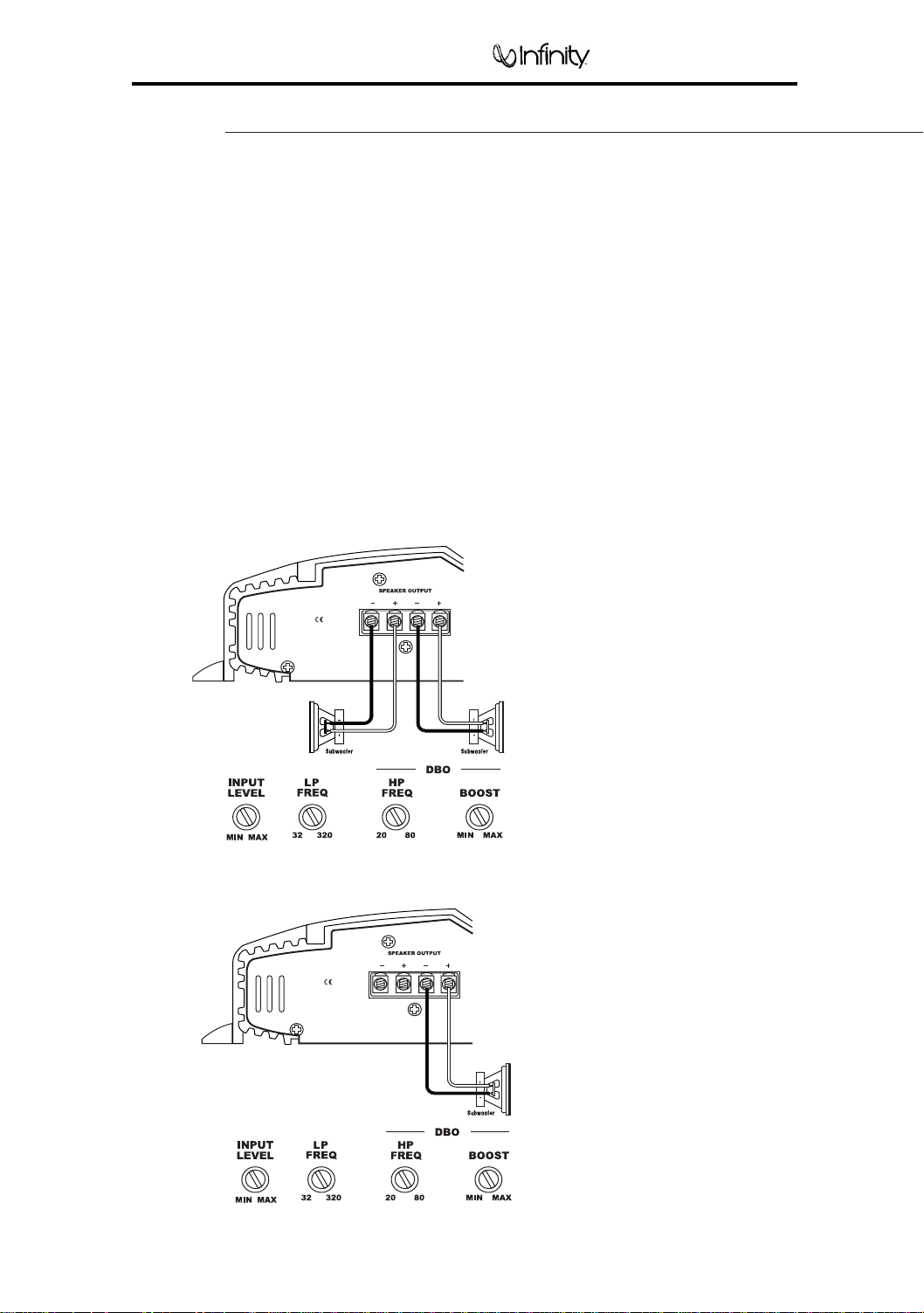
Figure 4. Reference subwoofer amplifier with one woofer connection.
Figure 3. Reference subwoofer amplifier with two woofer connections.
The Reference subwoofer amplifiers are
single-channel amplifiers. There are two sets of
terminals to make it easy to connect multiple
woofers. Either set of (+/–) terminals may be
used when connecting woofers.
To the right are two application diagrams to help
plan your subwoofer system installation. Figures
3 and 4 show how to configure the Reference
subwoofer amplifiers (models 311a, 611a and
1211a).
NOTE: For simplicity, Figures 3 and 4 do not
show power, remote and input connections.
NOTE: Minimum speaker load is 2 ohms.
Power Amplifier
4
Reference 1210a/1211a
A
PPLICATIONS
– 1201a/1211a
Page 6
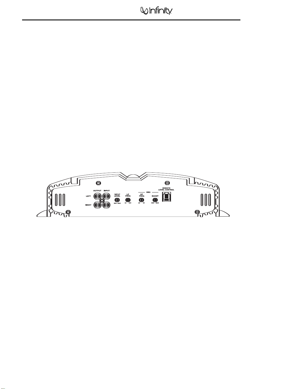
SETTING INPUT SENSITIVITY
1. Initially turn the INPUT LEVEL control(s) to
minimum (counterclockwise).
2. Reconnect the (–) negative lead to the vehi-
cle’s battery. Apply power to the audio system
and play a dynamic music track.
3. On the source unit, increase the volume
control to 3/4 volume. Slowly increase the
INPUT LEVEL control(s) toward three o’clock
until you hear slight distortion in the music.
Then reduce the INPUT LEVEL slightly until
distortion is no longer heard.
NOTE: After the source unit is on, blue LEDs (on
the top panel) will light, indicating the amplifier
is on. If not, check the wiring, especially the
remote connection from the source unit. Also
refer to “Troubleshooting” on page 7.
REMOTE LEVEL CONTROL (OPTIONAL)
All three Reference subwoofer amplifiers and
the 5761a amplifier have inputs for an optional
remote level control (100rc). This will allow the
subwoofer level to be adjusted from the listening
position. Connect the optional remote level
control using the RJ-11 jack on the side of the
amplifier. Install the control module in the front
of the vehicle within easy reach of the driver.
Both the underside of the dash and the center
console are suitable locations. Refer to the
mounting instructions accompanying the 100rc.
AUX OUTPUT
Reference amplifiers (except 5761a) are equipped
with full-range outputs that can be used to
connect additional amplifiers.
NOTE: When using the low- or high-level inputs,
the AUX outputs can be used to pass a full-range
line-level signal to another amplifier.
Figure 13. Control end panel.
Power Amplifier
5
Reference 1210a/1211a
Page 7
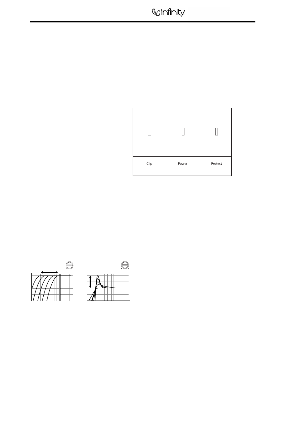
STATUS LEDs
Clip: Indicates the amplifier is being overdriven,
and your speakers may be in danger. This
should blink only on musical peaks, and not
be on constantly.
Power: Indicates the amplifier is on.
Protection: Refer to “Troubleshooting” for specific
indications.
Figure 15. LED status.
SETTING DBO
™
(310a, 610a and 1210a)
The Dynamic Bass Optimizer (DBO) is used to
enhance low-frequency reproduction in a vehicle.
Conventional bass-boost circuits only increase
bass at a fixed frequency, and cause the amplifier
to consume considerable power. The DBO allows
you to adjust the frequency (20Hz – 80Hz) as well
as the boost level (up to 12dB; see Figure 14),
allowing you to fine-tune the bass in your system
to optimize performance.
For sealed enclosures, the DBO can be used
to enhance the lower bass region of sealed
enclosures.
For bigger/fuller bass, adjust the HP FREQ
between 35Hz and 45Hz; adjust the BOOST
control according to your preference.
For tighter-sounding bass, adjust the HP FREQ
between 45Hz and 55Hz; adjust the BOOST
control according to your preference.
For vented enclosures, the DBO should be used
as a subsonic filter to reduce overexcursion
of the woofers. Set the HP FREQ control 10Hz
below the tuning frequency of the enclosure
(e.g., 25Hz for a box tuning of 35Hz); adjust the
BOOST control to taste. This will conserve
amplifier power typically wasted on frequencies
below the tuned frequency of the enclosure.
For infinite-baffle applications, set the HP FREQ to
the speaker’s Fs value (reducing overexcursion of
the woofer); adjust the Boost control to taste.
Figure 14. Frequency-response curves show
typical DBO control ranges.
INSTALLATION AND SETUP (CONT.)
-9
-6
-3
0
-12
20 80
Freq. (Hz)
dB
DBO HP FREQ Control
(adjusts cut-off
frequency)
HP FREQ
100Hz20Hz
-6
0
6
12
-12
20 80
Freq. (Hz)
dB
DBO BOOST Control
(adjusts boost amount
at cut-off frequency)
BOOST
MAX MIN
Power Amplifier Reference 1210a/1211a
6
Page 8

•
PROBLEM:
No audio (POWER LED is off).
CAUSE and SOLUTION:
No voltage at BATT+ and/or REM terminals, or
bad or no ground connection. Check voltages
at amplifier terminals with VOM.
•
PROBLEM:
No audio (PROTECT LED flashes every
4 seconds).
CAUSE and SOLUTION:
DC voltage on amplifier output. Amplifier may
need service; see enclosed warranty card for
service information.
•
PROBLEM:
No audio (PROTECT LED is on).
CAUSE and SOLUTION:
Amplifier is overheated. Make sure amplifier
cooling is not blocked at mounting location;
verify that speaker-system impedance is within
specified limits.
•
PROBLEM:
No audio (PROTECT and POWER LEDs flash).
CAUSE and SOLUTION:
Voltage less than 9V on BATT+ connection.
Check vehicle charging system.
•
PROBLEM:
No audio (PROTECT LED is on).
CAUSE and SOLUTION:
Voltage greater than 16V or less than 8.5V on
BATT+ connection. Check vehicle charging
system.
•
PROBLEM:
Distorted audio.
CAUSE and SOLUTION:
Input sensitivity is not set properly, or amplifier
or source unit is defective. Check INPUT LEVEL
setting, or check speaker wires for shorts or
grounds.
•
PROBLEM:
Distorted audio (PROTECT LED flashes).
CAUSE and SOLUTION:
Short circuit in speaker or wire. Remove
speaker leads one at a time to locate shorted
speaker or wire, then repair.
•
PROBLEM:
Music lacks “punch.”
CAUSE and SOLUTION:
Speakers are not connected properly. Check
speaker connections for proper polarity.
TROUBLESHOOTING
Power Amplifier Reference 1210a/1211a
7
Page 9
Power Amplifier Reference 1210a/1211a
8
Page 10
Reference 1210a/1211a
9
Page 11
Power Amplifier Reference 1210a/1211a
10
Page 12

Power Amplifier Reference 1210a/1211a
11
REFERENCE 1210A/1211a BLOCK DIAGRAM
Page 13

Power Amplifier Reference 1210a/1211a
12
Page 14

Power Amplifier Reference 1210a/1211a
13
Page 15

Power Amplifier Reference 1210a/1211a
14
Page 16

Power Amplifier Reference 1210a/1211a
15
Page 17

Power Amplifier Reference 1210a/1211a
16
Electrical Parts List
DIO-00-00108 DIODE FAST RECOVERY FR154 D71,72,73,81,82,83 6
DIO-00-00003 DIODE RECTIFIER 1N4004 D1,260 2
DIO-00-00019 DIODE ZENER 1W,12V 1N4742 D401 1
DIO-00-00006 DIODE SWITCHING SIGNAL 1SS133 / 1N4148 D169,402,403,404,405,406,407,408,411,412 10
TRS-00-00087 TRANSISTOR SMALL SIGNAL PNP "TO-92L" KTA1023Y Q402,403 2
TRS-00-00088 TRANSISTOR SMALL SIGNAL NPN "TO-92L" KTC1027Y Q270,271,401 3
TRS-00-00090 TRANSISTOR SMALL SIGNAL PNP "TO-92" KTA1266GR Q262 1
TRS-00-00110 TRANSISTOR SMALL SIGNAL NPN "TO-92" KTC3198GR Q101,260,261,263 4
RES-00-00479RESISTOR METAL FILM 1/5WF 270 OHM R405 1
RES-00-00437RESISTOR METAL FILM 1/5WF 1KF OHM R151,156 2
RES-00-00482RESISTOR METAL FILM 1/5WF 2KF OHM R117 1
RES-00-00523RESISTOR METAL FILM 1/5WF 4.7KF OHM R113 1
RES-00-00575RESISTOR METAL FILM 1/5WF 7.5KF OHM R118 1
RES-00-00589RESISTOR METAL FILM 1/5WF 9.4KF OHM R111,112 2
RES-00-00402RESISTOR METAL FILM 1/5WF 10KF OHM R150,152,155,157 4
RES-00-00419RESISTOR METAL FILM 1/5WF 13KF OHM R404 1
RES-00-00537RESISTOR METAL FILM 1/5WF 47KF OHM R103,104,105,106,107,108,109,110,402,403 10
RES-00-00606RESISTOR CARBON FILM 1/5WJ 100 OHM R51,52,53,54,55,56,61,62,63,64 13
RES-00-00622RESISTOR CARBON FILM 1/5WJ 150 OHM R125 1
RES-00-00712RESISTOR CARBON FILM 1/5WJ 470 OHM R241,264,341 3
RES-00-00723RESISTOR CARBON FILM 1/5WJ 510 OHM R120,122 2
RES-00-00756RESISTOR CARBON FILM 1/5WJ 820 OHM R116 1
RES-00-00633RESISTOR CARBON FILM 1/5WJ 1K OHM R50,57,60,67,153,158 6
RES-00-00598RESISTOR CARBON FILM 1/5WJ 1.5K OHM R133 1
RES-00-00602RESISTOR CARBON FILM 1/5WJ 1.8K OHM R135 1
RES-00-00702RESISTOR CARBON FILM 1/5WJ 4.7K OHM R114,262,414 3
RES-00-00720RESISTOR CARBON FILM 1/5WJ 5.6K OHM R131,132 2
RES-00-00608RESISTOR CARBON FILM 1/5WJ 10K OHM R44,119,123,128,129,130,261,263,406,407 16
RES-00-00623RESISTOR CARBON FILM 1/5WJ 15K OHM R121,126 2
RES-00-00630RESISTOR CARBON FILM 1/5WJ 18K OHM R415 1
RES-00-00658RESISTOR CARBON FILM 1/5WJ 22K OHM R101,102 2
RES-00-00666RESISTOR CARBON FILM 1/5WJ 27K OHM R417 1
RES-00-00680RESISTOR CARBON FILM 1/5WJ 30K OHM R124 1
RES-00-00730RESISTOR CARBON FILM 1/5WJ 56K OHM R270,271 2
RES-00-00757RESISTOR CARBON FILM 1/5WJ 82K OHM R169 1
RES-00-00604RESISTOR CARBON FILM 1/5WJ 100K OHM R134,138,154,159,230,231,232,233,234,236 22
RES-00-00620RESISTOR CARBON FILM 1/5WJ 150K OHM R127 1
RES-00-00654RESISTOR CARBON FILM 1/5WJ 220K OHM R413 1
RES-00-00727RESISTOR CARBON FILM 1/5WJ 560K OHM R408 1
RES-00-00755RESISTOR CARBON FILM 1/5WJ 820K OHM R260 1
RES-00-00635RESISTOR CARBON FILM 1/5WJ 1M OHM R411 1
RES-00-00018RESISTOR METAL FILM 1/2WJ 10 OHM R220,221,222,223,224,226,227,228,229,320 18
R409,410,412,416,418,419
R237,238,239,330,331,332,333,334,336,337
R338,339
R321,322,323,324,325,327,328,329
RES-00-00794RESISTOR METAL FILM 1WJ 10 OHM R73,83 2
IND-00-00025 INDUCTOR LAL02TB1R0K AXIAL TYPE 5% 1uH L1,2 2
CEC-00-00077CAPACITOR CERAMIC DISK 50V "NPO" 10pF C105,106 2
CEC-00-00090CAPACITOR CERAMIC DISK 50V "NPO" 22pF C131,132,133,134,153,154 6
CEC-00-00101CAPACITOR CERAMIC DISK 50V 470pF C109 1
CEC-00-00074CAPACITOR CERAMIC DISK 50V 102pF C7,107,108,111,406,701,900 7
CEC-00-00076CAPACITOR CERAMIC DISK 50V 104pF C41,42,73,83,170,171,172,173,174,175 24
C176,177,178,179,180,181,182,183,211,261
C262,401,403,411
CEC-00-00124CAPACITOR CERAMIC DISK 50V "MLCC" 104pF C55,409,410 3
ELC-00-00153 CAPACITOR ELECTROLYTIC"SMS" 1uF/50V C113,408 2
ELC-00-00160 CAPACITOR ELECTROLYTIC"SMS" 4.7uF/50V C71,81,114,407 4
ELC-00-00125 CAPACITOR ELECTROLYTIC"SMS" 10uF/16V C110,112 2
ELC-00-00127 CAPACITOR ELECTROLYTIC"SMS" 22uF/16V C101,102,103,104,115,121,151,152 8
ELC-00-00130 CAPACITOR ELECTROLYTIC"SMS" 47uF/16V C260 1
ELC-00-00523 CAPACITOR ELECTROLYTIC"SMS" 100uF/16V C75,85,404 3
ELC-00-00150 CAPACITOR ELECTROLYTIC"SMS" 100uF/35V C72,82 2
ELC-00-00132 CAPACITOR ELECTROLYTIC"SMS" 220uF/16V C270 1
Page 18

Power Amplifier Reference 1210a/1211a
17
Electrical Parts List cont'd
MYC-00-00020CAPACITOR MYLAR 5% 100V 102J C90,91,405 3
MYC-00-00019CAPACITOR MYLAR 5% 100V 103J C280,380 2
MYC-00-00091CAPACITOR MYLAR 5% 63V "TL TYPE" 683J C117 1
MYC-00-00157CAPACITOR MYLAR 5% 63V "TL TYPE" 823J C116 1
MYC-00-00083CAPACITOR MYLAR 5% 63V "TL TYPE" 104J C222 1
MYC-00-00156CAPACITOR MYLAR 5% 63V "TL TYPE" 184J C119 1
MYC-00-00066CAPACITOR MYLAR 5% 63V "TL TYPE" 474J C74,84,118 3
MYC-00-00085CAPACITOR MYLAR 5% 63V "TL TYPE" 105J C2,6,43 3
ICO-00-00003 I.C DUAL OPAMP DIP-08 TL072CP U101,102,103,104,105 5
ICO-00-00170 I.C VOLUME IC DIP-16 NJM 13600D U106 1
ICO-00-00095 I.C COMPORATOR IC DIP-08 KIA393P U401 1
ICO-00-00157 I.C VOTAGE REGULATOR +12V 1A KIA7812PI U71 1
ICO-00-00162 I.C VOTAGE REGULATOR -12V 1A KIA7912PI U81 1
FET-00-00001 F.E.T
FET-00-00046 F.E.T
FET-00-00021 F.E.T P-CH POWER MOSFET IRF9640 Q211,212,213,214,215,311,312,313,314,315 10
DIO-00-00152 DIODE FAST RECOVERY YG225D2 D74,75,76,77 4
DIO-00-00177 DIODE FAST RECOVERY 6A60 D2 1
RES-00-01112RESISTOR MOR-S 2WJ 2.2 OHM R253 1
RES-00-00846RESISTOR MOR-S 2WJ 10 OHM R71,81 2
RES-00-00844RESISTOR MOR-S 2WJ 100 OHM R77,78 2
RES-00-00853RESISTOR MOR-S 2WJ 2.2K OHM R250,251,252,254,255,280,380,401 8
RES-00-01099RESISTOR MOR-S 2WJ 3.9K OHM R76,86 2
RES-00-00947RESISTOR SHUNT RESISTOR 5WJ (3P) 0.01 OHM R240,340 2
ELC-00-00167 CAPACITOR ELECTROLYTIC"SMS" 100/63V C402 1
ELC-00-00010 CAPACITOR ELECTROLYTIC"BP" 10/200V C215,216,217,218,221 5
ELC-00-00187 CAPACITOR ELECTROLYTIC"SHL" 2200/50V C208,210,308,310 4
ELC-00-00716 CAPACITOR ELECTROLYTIC"LXZ" 3300/25V C50,51,52,53,54 5
ELC-00-00033 CAPACITOR ELECTROLYTIC"HC" 8200/50V C76,86 2
MYC-00.-0010CAPACITOR MYLAR 10% 100V "BOX TYPE" 105K C92,93,207,219,220,307 6
MYC-00.-0007CAPACITOR MYLAR 10% 100V "BOX TYPE" 225K C78,88,212,213,312,313 6
MYC-00.-0010CAPACITOR MYLAR 10% 250V "BOX TYPE" 225K C223,820 2
COI-00-00086 INDUCTOR DRUM COIL CL-900A L6,7,9 3
COI-00-00073 INDUCTOR DRUM COIL CL-2200 L3 1
COI-00-00112 INDUCTOR DRUM COIL CL-1920 L8 1
GAP-00-050A0GAP PAD CL-1920 (32 X 60 X 5T) L8 1
COR-TF-00392CORE 44 PHI MAG T1,T2 , 44PHI 3T(0.7X22):10T(0.7X5):3T(0.7X1) 2
TER-00-00163
TER-00-00034
HOD-00-00006FUSE HOLDER PCB TYPE JSF-08031 FUSE1,2,3 3
FUS-AT-00008AUTO FUSE AUTO FUSE 40A SET(3)+ACCESSORY(3) 6
POWER
SPEAKER
N-CH POWER FET "TO-220"
N-CH POWER FET "TO-220"
3P TERMINAL DST 0010-00 TER1 1
4P TERMINAL TM0009-01 TER2 1
IRF3205 Q51,52,53,54,55,56,61,62,63,64 12
Q65,66
IRF640N Q217,218,219,220,317,318,319,320 8
JAC-00-00043 RCA JACK GOLD PLATE DJB-554A RCA101 1
JUP-00-00003 JUMPER
JUP-00-00005 JUMPER
JAC-00-00050 MODULAR JACK 4P,BLACK DEK623PCB4-B MOD1 1
REL-00-00008 RELAY DC 30A 12V CT11-D12S REL1 1
THS-00-00013THERMISTOR FTD5-350 50KC TH 1
VOL-00-00335VOLUME V12L5(9X5)G(PH2D)N15S 15B20Kx2 VR101 1
VOL-00-00336VOLUME V12L5(9X5)G(PH2D)N15S 15C50Kx2 VR102 1
VOL-00-00352 VOLUME V12L5(9X5) G(PH2D)N 15S B500x2
VOL-00-00353 VOLUME
WIR-00-00017 GND WIRE #1007 AWG #22 BLACK , 3.2PHI 100m/m W1 1
WIR-00-00111 GND WIRE #1007 AWG #22 BLACK , 3.2PHI 60m/m W2 1
WIR-00-00018 GND WIRE #1007 AWG #22 BLACK , 3.2PHI 120 m/m W3 1
TUB-00-00008TEFLON TUBE 0.7 PHI 10 m/m TH 2
CON-00-00002WAFER LWL0640-2P CLIP 1
CON-00-00033WAFER LWL0640-3P 1ST POWER,2ST POWER 2
BAR JUMP
BAR JUMPER
V12L5(9X5) G(4R)(PH2D)N 15S 15A2Kx2+15A200Kx2
35m/m JP1,2,3,4,5,6,7,8,9 9
55 m/m JP10,11,12,13,14,15,16 7
VR103 1
VR104 1
Page 19

Power Amplifier Reference 1210a/1211a
18
Electrical Parts List cont'd
ICO-00-00021 I.C SMD PWM TL494C U1 1
ICO-00-00094 I.C SMD "FLP-8" KIA393F U2,3 2
TRS-00-00098 TRANSISTOR SMALL SIGNAL PNP,SOT-23 KTA1504GR Q3,4,5 3
TRS-00-00113 TRANSISTOR SMALL SIGNAL NPN,SOT-23 KTC3875GR Q2,6 2
DIO-00-00117 DIODE SWITCHING SIGNAL RLS4148 D3,4,5,6,7,8 6
RES-08-00035RESISTOR SMD "0805"1/10WF 20KF OHM R32 1
RES-08-00048RESISTOR SMD "0805"1/10WF 27KF OHM R33 1
RES-08-00111RESISTOR SMD "0805"1/10WF 68KF OHM R29 1
RES-08-00021RESISTOR SMD "0805"1/10WF 150KF OHM R28 1
RES-08-00193RESISTOR SMD "0805"1/10WJ 4.7 OHM R11 1
RES-08-00163RESISTOR SMD "0805"1/10WJ 220 OHM R30 1
RES-08-00148RESISTOR SMD "0805"1/10WJ 1K OHM R16,38,39,43,46 5
RES-08-00129RESISTOR SMD "0805"1/10WJ 1.8K OHM R2 1
RES-08-00151RESISTOR SMD "0805"1/10WJ 2.2K OHM R9,10 2
RES-08-00156RESISTOR SMD "0805"1/10WJ 2.7K OHM R3 1
RES-08-00191RESISTOR SMD "0805"1/10WJ 4.7K OHM R7,8,17,24,25,27 6
RES-08-00200RESISTOR SMD "0805"1/10WJ 5.1K OHM R6 1
RES-08-00201RESISTOR SMD "0805"1/10WJ 5.6K OHM R18,19 2
RES-08-00132RESISTOR SMD "0805"1/10WJ 10K OHM R34 1
RES-08-00164RESISTOR SMD "0805"1/10WJ 22K OHM R12,14,15,22,26 5
RES-08-00170RESISTOR SMD "0805"1/10WJ 27K OHM R13 1
RES-08-00182RESISTOR SMD "0805"1/10WJ 33K OHM R5 1
RES-08-00130RESISTOR SMD "0805"1/10WJ 100K OHM R20 1
RES-08-00180RESISTOR SMD "0805"1/10WJ 330K OHM R4 1
RES-08-00149RESISTOR SMD "0805"1/10WJ 1M OHM R21,23,31,35 4
RES-12-00189RESISTOR SMD "1206"1/8WJ 4.7 OHM R1 1
CEC-08-00002CAPACITOR CHIP"0805" 50V 5% 102P C8 1
CEC-08-00040CAPACITOR CHIP"0805" 50V 5% 473P C5 1
CEC-08-00004CAPACITOR CHIP"0805" 50V 5% 104P C3,14,18,20,22 5
TRS-00-00087 TRANSISTOR SMALL SIGNAL PNP KTA1023Y Q1 1
TRS-00-00090 TRANSISTOR SMALL SIGNAL PNP KTA1266GR Q7,8,9,10 4
RES-00-00038RESISTOR METAL FILM 1/2WJ 220 OHM R36,37 2
ELC-00-00250 CAPACITOR ELECTROLYTIC"SRE" 4.7uF/50V C4,9,11,17,23 5
ELC-00-00641 CAPACITOR ELECTROLYTIC"SRE" 22uF/16V C15,16 2
ELC-00-00243 CAPACITOR ELECTROLYTIC"SRE" 100uF/16V C10,12 2
MYC-00-00020CAPACITOR MYLAR 5% 100V 102J C13 1
HED-00-00100HEADER PIN PIN HEADER C-TYPE 6P TM2007-C9G-06P HP1 1
HED-00-00228HEADER PIN PIN HEADER C-TYPE 8P TM2007-C9G-08P HP2 1
ICO-00-00005 I.C SMD QUAD OP AMP "SO-14" TL074CD U501 1
ICO-00-00099 I.C 2.5V SHUNT IC , SOT-89 KIA431F U505 1
ICO-00-00054 I.C DIVIDER
ICO-00-00546 I.C COMPARATOR "SO-14"
TRS-00-00197 TRANSISTOR HIGH CURRENT PNP,SOT-89 KTA1661Y Q503 1
TRS-00-00115 TRANSISTOR HIGH CURRENT NPN,SOT-89 KTC4373Y Q502 1
TRS-00-00113 TRANSISTOR SMALL SIGNAL NPN,SOT-23 KTC3875GR Q501 1
DIO-00-00117 DIODE SWITCHING SIGNAL RLS4148 D501,502,503,504,505 5
RES-08-00005RESISTOR SMD "0805"1/10WF 1.5KF OHM R558 1
RES-08-00077RESISTOR SMD "0805"1/10WF 4.7KF OHM R505,506 2
RES-08-00135RESISTOR SMD "0805"1/10WJ 10 OHM R508 1
RES-08-00165RESISTOR SMD "0805"1/10WJ 22 OHM R528 1
RES-08-00131RESISTOR SMD "0805"1/10WJ 100 OHM R555 1
RES-08-00148RESISTOR SMD "0805"1/10WJ 1K OHM R509,521,529,553,554 5
RES-08-00126RESISTOR SMD "0805"1/10WJ 1.5K OHM R511 1
RES-08-00151RESISTOR SMD "0805"1/10WJ 2.2K OHM R517 1
RES-08-00174RESISTOR SMD "0805"1/10WJ 3.3K OHM R522 1
RES-08-00191RESISTOR SMD "0805"1/10WJ 4.7K OHM R515,516,552 3
RES-08-00132RESISTOR SMD "0805"1/10WJ 10K OHM R507,525,526,551,556,559 6
RES-08-00164RESISTOR SMD "0805"1/10WJ 22K OHM R523 1
RES-08-00187RESISTOR SMD "0805"1/10WJ 39K OHM R503,504 2
F4
B2
U503 1
U504 1
Page 20

Power Amplifier Reference 1210a/1211a
19
RES-08-00198RESISTOR SMD "0805"1/10WJ 47K OHM R513 1
RES-08-00204RESISTOR SMD "0805"1/10WJ 51K OHM R512 1
RES-08-00221RESISTOR SMD "0805"1/10WJ 75K OHM R514 1
RES-08-00130RESISTOR SMD "0805"1/10WJ 100K OHM R510 1
RES-08-00149RESISTOR SMD "0805"1/10WJ 1M OHM R520,524,527 3
RES-12-00161RESISTOR SMD "1206"1/8WJ 22 OHM R550,557 2
CEC-08-00042CAPACITOR CHIP"0805" 50V 5% 47pF C510,511,517 3
CEC-08-00028CAPACITOR CHIP"0805" 50V 5% 330pF C505,515,516 3
CEC-08-00004CAPACITOR CHIP"0805" 50V 5% 104pF C512,518,520,523,524,526,528,529,530 9
CEC-12-00008CAPACITOR CHIP"1206" 50V 5% 105pF C521 1
ELC-00-00077 CAPACITOR ELECTROLYTIC CHIP "MV" 2.2uF/50V C1,525,531 3
ELC-00-00070 CAPACITOR ELECTROLYTIC CHIP "MV" 4.7uF/25V C513,522,527 3
ELC-00-00356 CAPACITOR ELECTROLYTIC CHIP "MV" 10uF/16V C533 1
ELC-00-00635 CAPACITOR ELECTROLYTIC CHIP "BP" 22uF/16V"NP" C504 1
MYC-00-00019CAPACITOR MYLAR 5% 100V 103J C514 1
IND-00-00020 INDUCTOR AXIAL TYPE 5% 100uH L501 1
REN-00-00001RESONATOR
2.56MHz CSA256MG
Electrical Parts List cont'd
X501 1
VOL-00-00238VOLUME
HED-00-00214HEADER PIN PIN HEADER C-TYPE 3P TM2007-C9G-03P HP2
HED-00-00215HEADER PIN PIN HEADER C-TYPE 7P TM2007-C9G-07P HP3
DIO-00-00041 DIODE ZENER 0.5W,12V 1N5242 D201,202 2(4)
TRS-00-00087 TRANSISTOR SMALL SIGNAL PNP "TO-92L" KTA1023Y Q204,206,208,210 4(8)
TRS-00-00088 TRANSISTOR SMALL SIGNAL NPN "TO-92L" KTC1027Y Q203,205,207,209 4(8)
RES-00-00401RESISTOR METAL FILM 1/5WF 100 OHM R204 1(2)
RES-00-00463RESISTOR METAL FILM 1/5WF 220 OHM R203 1(2)
RES-00-00590RESISTOR METAL FILM 1/5WF 910 OHM R202,206 2(4)
RES-00-00636RESISTOR CARBON FILM 1/5WJ 1 OHM R207,208,211,212 4(8)
RES-00-00685RESISTOR CARBON FILM 1/5WJ 330 OHM R420,421 2(4)
RES-00-00637RESISTOR CARBON FILM 1/5WJ 2.2K OHM R201,205 2(4)
CEC-00-00076CAPACITOR CERAMIC DISK 50V 104pF C201,202,204,205 4(8)
MYC-00-00088CAPACITOR MYLAR 5% 63V "TL TYPE" 224J C203,206 2(4)
RES-00-01033RESISTOR MOR-S 2WJ "3.8x11" 4.7K OHM R209,210,213,214 4(8)
TRS-00-00096 TRANSISTOR SMALL SIGNAL PNP
TRS-00-00112 TRANSISTOR SMALL SIGNAL NPN
HED-00-00214HEADER PIN PIN HEADER C-TYPE 3P TM2007-C9G-03P HP1 1(2)
HED-00-00231HEADER PIN PIN HEADER C-TYPE 5P TM2007-C9G-05P HP7 1(2)
ICO-00-00095
I.C COMPARATOR DIP-8P KIA393P U90 1
SEMI X-TYPE (RG06X502)
5K SEMI VR501 1
KSA/KTA1381
KSC/KTC3503
Q202 1(2)
Q201 1(2)
RES-00-00437
RES-00-00402
RES-00-00550
RES-00-00556
RES-00-00573
RES-00-00635
RES-00-00029
CEC-00-00005
CEC-00-00006
DIO-00-00321
CON-00-00139
CON-00-00140
WIR-AS-00220
WIR-AS-00218
WIR-AS-00219
RESISTOR METAL FILM 1/5WF 1K OHM R97
RESISTOR METAL FILM 1/5WF 10K OHM R95
RESISTOR METAL FILM 1/5WF 51K OHM R96
RESISTOR METAL FILM 1/5WF 56K OHM R94
RESISTOR METAL FILM 1/5WF 68K OHM R93
RESISTOR CARBON FILM 1/5WJ 1M OHM R98
RESISTOR METAL FILM 1/2WJ 1K OHM R192,292
CAPACITOR CERAMIC TUBULAR 50V 103P C91,92,93
CAPACITOR CERAMIC TUBULAR 50V 104P C90
LED BLUE 3PHI
WAFER
WAFER
WIRE ASS'Y BK,RED
WIRE ASS'Y BK,RED,GREEN
WIRE ASS'Y BK,YELLOW,GREEN
MS-L330CBHSK
LAL0640-2P
LAL0640-3P
CHL0640-2P(300m/m)
CHL0640-3P(300m/m)
CHL0640-3P(300m/m)
LED1,2,3 3
CLIP 1
1ST POWER,2ND POWER 2
CLIP 1
1ST POWER 1
2ND POWER 1
1
1
1
1
1
1
2
3
1
Page 21

20
Power Amplifier
Reference 1211a Electrical Parts List Addendum
The following chart below represents the only electrical parts
differences in 1210a and 1211a models:
MODEL PART NAME PART NUMBER SPEC DESIGNATOR
REF 1210a RE S ISTOR RES-00-00756 1/5WF 820 OHM R116
1
REF 1211a RE S ISTOR RES-00-00474 1/5WF 240 OHM R116
REF 1210a RE S ISTOR RES-00-00482 1/5WF 2K OHM R117
2
REF 1211a RE S ISTOR RES-00-00577 1/5WF 750 OHM R117
REF 1210a RE S ISTOR RES-00-00575 1/5WF 7.5K OHM R118
3
REF 1211a RE S ISTOR RES-00-00402 1/5WF 10K OHM R118
Reference 1210a/1211a
REF 1210a POWER TERMINAL TER-00-00163 (3P) DST0010-00 TER1
3
REF 1211a
REF 1210a SPEAKER TERMINAL TER-00-00034 (4P) TM0009-01 TER2
4
REF 1211a
POWER TERMINAL
SPEAKER TERMINAL
TER-00-00278 (3P) DK-03B04-AG-5-UP TER1
TER-00-00276 (4P) DK-04A04-AG-5-UP TER2
Page 22

Power Amplifier
21
Reference 1210a/1211a
Page 23

Power Amplifier Reference 1210a/1211a
22
Page 24

Power Amplifier Reference 1210a/1211a
23
Page 25

Power Amplifier
24
Reference 1210a/1211a
Page 26

Power Amplifier Reference 1210a/1211a
25
Page 27

Power Amplifier Reference 1210a/1211a
26
Page 28

27
Protect LED
Page 29

28
Page 30

29
Page 31

30
Power Amplifier Reference 1211a
REF 1211a SCHEMATIC PAGE 1
Page 32

31
Power Amplifier Reference 1211a
REF 1211a SCHEMATIC PAGE 2
Page 33

32
Power Amplifier Reference 1211a
REF 1211a SCHEMATIC PAGE 3
Page 34

Power Amplifier Reference 1210a/1211a
33
PACKING EXPLODED VIEW
 Loading...