

Page 1
108IL10B
108IL10C
108IL30B
108IL30C
108IL40B
108IL40C
INTERLUDE™SPEAKER SYSTEMS
Owner’s Guide
• IL10
• IL30
• IL40
Page 2
Infinity Interlude Series
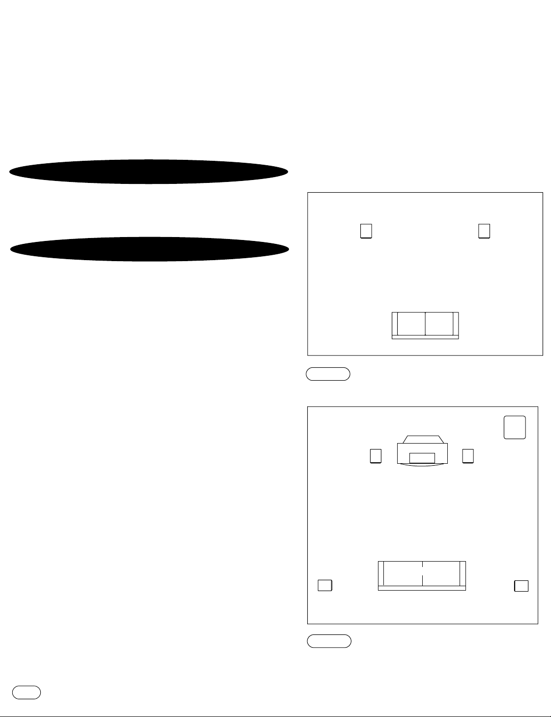
Listening Position
Left
Channel
Right
Channel
Couch
Left
Front
Channel
Left
Surround
Channel
Right
Surround
Channel
Right
Front
Channel
Center
Channel
Infinity
Subwoofer
(optional)
The Interlude Series of loudspeakers continues Infinity’s
longstanding commitment to accurate sound reproduction.
Our proprietary Ceramic Metal Matrix Diaphragm™(C.M.M.D.)
drivers,precision dividing networks and rigid, well-braced
enclosures combine to deliver uncompromised performance in
any stereo or multichannel home-theater system.In addition,
the IL10,IL30 and IL40 are magnetically shielded for safe
placement adjacent to a television.
UNPACKING THE
If you suspect damage from transit,report it immediately to
your dealer.Keep the shipping carton and packing materials
for future use.
SPEAKERS
PLACEMENT
Stereo
Before deciding where to place your Interlude speakers,survey
your room and think about placement,keeping the following
points in mind:
•
For best results,place the speakers 6'–8' apart.
•
Position each speaker so that the tweeter is at approximately
ear level.
•
Generally,bass output will increase as the speaker is moved
closer to a wall or corner.
•
Refer to “Home Theater” below if you also plan to use the
speakers for home-theater reproduction.
Home Theater
For front-channel use,place one speaker on the left and another
on the right along either side of the television monitor.Since the
speakers are magnetically shielded,you can place them without
worrying about the field distorting the TV picture.
Forrear-channel use,place speakers on bookshelves or stands
alongside the listening position.Final placement depends on
room acoustics,availability of space and your listening
preference (Figure 2).
NOTE:An Infinity powered subwoofer will add impact and
realism to both music and film soundtracks.Contact your local
Infinity dealer for recommendations on subwoofer models for
your application.
FIGURE 1
bass level and stereo imaging in your room.
– Experiment with speaker placement to obtain the best
2
INTERLUDE
FIGURE 2
– This overhead view shows a typical home-theater plan.
Page 3
NSTALLING FEET
Nylon Dome
(optional for
wood floors)
Locking Nut
HARD-SURFACE
FLOORS
CARPETED
FLOORS
Foot
round end
spike end
Bottom
of Speaker
5
⁄8"
5
⁄8" min.
1
1
⁄8" max.
I
IL30 and IL40
Refer to Figure 3 as you perform the following steps:
1. Open each accessory pack and locate the following items:
four feet (with spike/round ends),four locking nuts,four
nylon domes and one wrench.
2. Lay each speaker on its side and locate the four threaded
holes on the bottom.
3. For carpets,screw the round end of a foot into each hole
and hand-tighten a nut onto each one.Leave a minimum of
5/8" of exposed spike.(On thicker carpets,you can increase
the length of exposed spike up to 1-1/8.") For hard-surface
floors,screw the spike end into each hole instead and leave
5/8" of round end exposed.
4. Carefully flip each speaker upright to sit on its feet.
5. If needed,adjust the feet so each speaker is level and then
tighten each nut with the enclosed wrench.To protect hard
surfaces (e.g.,wood floors),slip a nylon dome onto each
round end.
FIGURE 3
onto the bottom of an IL30 or IL40 floorstanding speaker.
– This cross section shows how to install a foot
INTERLUDE
3
Page 4
+
+
–
–
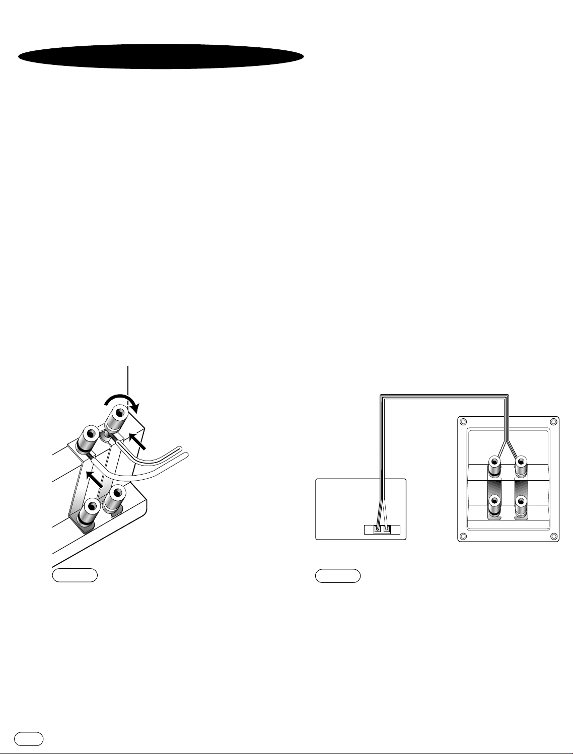
1. Loosen the terminals.
2. Insert bare ends;
tighten terminals.
+–
Receiver or
Amplifier
(rear view)
+
–
Speaker
(rear view)
Standard
Connection
(one channel shown)
IRING THE SYSTEM
W
IMPORTANT:Make sure all equipment is turned off before
making any connections.
For speaker connections,use a minimum #16-gauge speaker
wire with polarity coding.The side of the wire with a ridge or
other coding is usually considered positive polarity (i.e.,+).
NOTE: If desired,consult your local Infinity dealer about speaker
wire and connection options.
The speakers have coded terminals that accept a variety of wire
connectors.The most common connection is shown in Figure 4.
To ensure proper polarity,connect each + terminal on the back
of the amplifier or receiver to the respective + (red) terminal on
each speaker,as shown in Figure 5.Connect the –(black)
terminals in a similar way.See the owner’s guides that were
included with your amplifier,receiver and television to confirm
connection procedures.
IMPORTANT: Do not reverse polarities (i.e.,+ to –or –to +)
when making connections.Doing so will cause poor imaging and
diminished bass response.
4
FIGURE 4
terminals.Banana plugs may also be inserted directly into the rear of the
connector.
– This example shows how to connect bare wires to the
INTERLUDE
FIGURE 5
channel of a stereo or home-theater system.
– Wiring diagram shows polarity connections for one
Page 5

1. Loosen the terminals and remove
strapping bars.
2. Insert the speaker wire for the
high frequencies into the top set
of terminals and tighten.
3. Insert the speaker wire for the
low frequencies into the bottom
set of terminals and tighten.
+
+
+
–
–
–
+
+
–
–
Right
Speaker
HF
LF
+
+
–
–
Left
Speaker
Receiver/
Amplifier
HF
LF
Right
Left
+
+
–
–
+
+
–
–
Right
Speaker
HF
LF
+
+
–
–
Left
Speaker
Amplifier 2
Amplifier 1
HF
LF
Right Left
++
––
Right Left
++
––
BI-WIRING
The Interlude Series outer connection panel and internal dividing
network are designed so that separate sets of speaker cables can be
attached to the low-frequency transducer and midrange/high-frequency
transducer portions of this dividing network.This is called bi-wiring.
Bi-wiring can provide several sonic advantages and considerably more
flexibility in power amplifier selection.
6
FIGURE
Single-Stereo Amplifier
FIGURE 7
Dual-Stereo Amplifier
FIGURE 8
INTERLUDE
5
Page 6

INAL ADJUSTMENTS
F
Check the speakers for playback first by setting the system
volume control to a minimum level,and then by applying power to
your audio system.Play a favorite music or video segment and
increase the system volume control to a comfortable level.
NOTE:You should hear balanced audio reproduction across the
entire frequency spectrum.If not,check all wiring connections or
consult the authorized Infinity dealer from whom you purchased
the system for more help.
The amount of bass you hear and the stereo-image quality will be
affected by a number of different factors,including the room’s
size and shape,the construction materials used to build the
room,the listener’s position relative to the speakers,and the
position of the speakers in the room.
Listen to a variety of music selections and note the bass level.
If there is too much bass,move the speakers away from nearby
walls.Conversely,if you place the speakers closer to the walls,
there will be more bass output.
Nearby reflecting surfaces can adversely affect stereo-imaging
quality.If this happens,try angling the speakers slightly inward
toward the listening position until the desired effect is achieved.
CARE OFYOUR SPEAKER SYSTEM
Each Interlude Series cabinet has a wood-vinyl finish that
does not require any routine maintenance.When needed,use
a soft cloth,dampened with water only,to remove any
fingerprints or dust.
Clean the grille by gentle vacuuming.
NOTE: Do not use any cleaning products or polishes on the
cabinet or grille.
6
INTERLUDE
Page 7

SPECIFICATIONS
IL10 IL30 IL40
Frequency Range: 56Hz – 22,000Hz (±3dB) 48Hz – 22,000Hz (±3dB) 38Hz – 22,000Hz (±3dB)
Recommended
Amplifier Power Range: 15 – 150 watts 15 – 150 watts 15 – 175 watts
Sensitivity: 88dB 88dB 89dB
(2.83V @ 1 meter)
Nominal Impedance: 8Ω 8Ω 8Ω
Crossover Frequency: 2800Hz;24dB/octave 2800Hz;24dB/octave 600Hz,2500Hz; 24dB/octave
Low-Frequency Driver: 6-1/2" (165mm) C.M.M.D., 6-1/2" (165mm) C.M.M.D., 8" (203mm) C.M.M.D.,
magnetically shielded magnetically shielded magnetically shielded
Mid-Frequency Driver: N/A N/A 4" (102mm) C.M.M.D.,
magnetically shielded
High-Frequency Driver: 1" (25mm) C.M.M.D., 1" (25mm) C.M.M.D., 1" (25mm) C.M.M.D.,
magnetically shielded magnetically shielded magnetically shielded
Dimensions:(H x W x D) 15-5/8" x 8-1/2" x 11-1/2" 36" x 8-1/2"x 8-3/4" 40" x 10"x 11-1/2"
(397mm x 216mm x 292mm) (914mm x 216mm x 222mm) (1016mm x 254mm x 292mm)
Weight: 18lb (8.2kg) 34lb (15.5kg) 41lb (18.6kg)
Declaration of Conformity
We, Infinity Systems A/S
Kongevejen 194B
DK-3460 Birkerød
DENMARK
declare in own responsibility, that the products described
in this owner’s manual are in compliance with technical
standards:
EN 50081-1:1992
EN 50082-1:1992
Infinity continually strives to update and improve existing products,as well
as create new ones.The specifications and construction details in this and
related Infinity publications are therefore subject to change without notice.
Steen Michaelsen
Infinity Systems A/S
Birkerød.DENMARK.12/99
INTERLUDE
7
Page 8

250 Crossways Park Drive,Woodbury,NY 11797 USA
(800) 553-3332 (USA Only)
Infinity is a registered trademark of Infinity Systems, Inc. Printed in USA 12/99 Part No.335755-001
© 1999 Infinity Systems,Inc.
www.infinitysystems.com
Page 9

Page 10

Page 11

 Loading...