

Page 1
2018 Q50 HYBRID
Roadside Assistance Guide
Page 2
Foreword
This manual describes roadside assistance operations and important safety related warnings and
cautions for this vehicle.
This vehicle is equipped with a high-voltage battery pack. Failure to follow recommended practices
during emergency responses will cause death or serious personal injury.
Please read this manual in advance in order to understand the features of this vehicle and to help you deal
with roadside assistance operations involving this vehicle. Follow the procedures in order to help assure
a safe and successful roadside assistance operation.
This manual is periodically updated. If you are not viewing this manual on the Infiniti web site, we urge you to
go to www.infinitiusa.com or www.infiniti-techinfo.com to make sure you have the most recent version of this
manual.
INFINITI
EMERGENCY CONTACT INFORMATION
• Infiniti Consumer Affairs: 1-800-662-6200 (US) or 1-800-361-4792 (Canada)
• Hours of operation are 8am - 5pm (Monday-Friday) Eastern, Central and Pacific time zones
IMPORTANT INFORMATION ABOUT THIS MANUAL
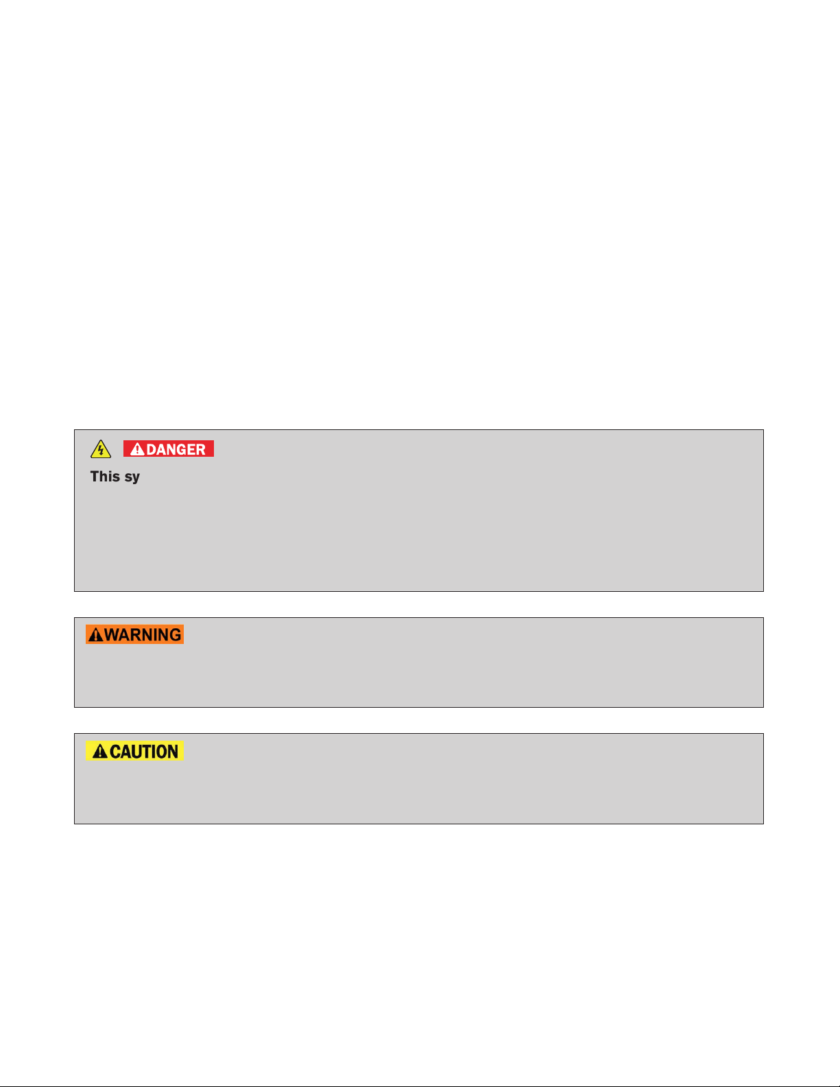
You may see various symbols in this manual. They have the following meanings:
DANGER
This symbol is used to inform you of an operation which will result in death or serious
personal injury if instructions are not followed.
Example: Touching high-voltage components without using the appropriate protective
equipment will result in electrocution. PPE must always be worn when touching or
working on high-voltage components.
This symbol is used to inform you of an operation which may cause death or serious
personal injury if instructions are not followed.
This symbol is used to inform you of an operation which may cause personal injury or
component damage if instructions are not followed.
Please note that there may be differences between this manual and the vehicle specification due to
specification changes.
RAG–2
Page 3

Table of Contents
FOREWORD . . . . . . . . . . . . . . . . . . . . . . . . . . . . . . . . . . . . . . . . . . . . . . . . . . . . . . . . . . . . . . . . . . RAG–2
INFINITI EMERGENCY CONTACT INFORMATION . . . . . . . . . . . . . . . . . . . . . . . . . . . . . . . . . . RAG–2
IMPORTANT INFORMATION ABOUT THIS MANUAL . . . . . . . . . . . . . . . . . . . . . . . . . . . . . . . . RAG–2
1. ABOUT THE INFINITI Q50 HYBRID . . . . . . . . . . . . . . . . . . . . . . . . . . . . . . . . . . . . . . . . . . . . . . RAG–5
1-1 Q50 HYBRID IDENTIFICATION . . . . . . . . . . . . . . . . . . . . . . . . . . . . . . . . . . . . . . . . . . . . . RAG–6
1-1.1 EXTERIOR AND ENGINE COMPARTMENT . . . . . . . . . . . . . . . . . . . . . . . . . . . . . . . RAG–6
1-1.2 INTERIOR . . . . . . . . . . . . . . . . . . . . . . . . . . . . . . . . . . . . . . . . . . . . . . . . . . . . . . . . . RAG–7
1-2 VEHICLE IDENTIFICATION NUMBER (VIN) LAYOUT . . . . . . . . . . . . . . . . . . . . . . . . . . . . . RAG–8
1-3 WARNING AND INDICATOR LAMP INFORMATION . . . . . . . . . . . . . . . . . . . . . . . . . . . . . RAG–9
2. BASIC HIGH-VOLTAGE INFORMATION . . . . . . . . . . . . . . . . . . . . . . . . . . . . . . . . . . . . . . . . . RAG–10
2-1 BATTERY INFORMATION . . . . . . . . . . . . . . . . . . . . . . . . . . . . . . . . . . . . . . . . . . . . . . . . . RAG–10
2-1.1 12-VOLT BATTERY . . . . . . . . . . . . . . . . . . . . . . . . . . . . . . . . . . . . . . . . . . . . . . . . . RAG–10
2-1.2 HIGH-VOLTAGE BATTERY . . . . . . . . . . . . . . . . . . . . . . . . . . . . . . . . . . . . . . . . . . . RAG–10
2-2 HIGH-VOLTAGE-RELATED AND 12-VOLT-RELATED COMPONENT LOCATIONS
AND DESCRIPTIONS . . . . . . . . . . . . . . . . . . . . . . . . . . . . . . . . . . . . . . . . . . . . . . . . . . . . RAG–11
2-3 HIGH-VOLTAGE BATTERY PACK SPECIFICATIONS . . . . . . . . . . . . . . . . . . . . . . . . . . . RAG–12
2-4 HIGH-VOLTAGE SAFETY MEASURES . . . . . . . . . . . . . . . . . . . . . . . . . . . . . . . . . . . . . . RAG–13
2-4.1 WARNING LABELS . . . . . . . . . . . . . . . . . . . . . . . . . . . . . . . . . . . . . . . . . . . . . . . . RAG–13
3. ROADSIDE ASSISTANCE RESPONSE STEPS . . . . . . . . . . . . . . . . . . . . . . . . . . . . . . . . . . . . RAG–15
3-1 PREPARATION ITEMS . . . . . . . . . . . . . . . . . . . . . . . . . . . . . . . . . . . . . . . . . . . . . . . . . . . RAG–15
3-1.1
3-1.2 DAILY INSPECTION . . . . . . . . . . . . . . . . . . . . . . . . . . . . . . . . . . . . . . . . . . . . . . . . RAG–16
3-1.3 INSULATED TOOLS . . . . . . . . . . . . . . . . . . . . . . . . . . . . . . . . . . . . . . . . . . . . . . . . RAG–16
3-2 INDICATIONS THE HIGH-VOLTAGE SYSTEM IS ON . . . . . . . . . . . . . . . . . . . . . . . . . . . RAG–16
3-3 VEHICLE IMMOBILIZATION AND STABILIZATION . . . . . . . . . . . . . . . . . . . . . . . . . . . . . . RAG–17
3-4 TURNING OFF THE IGNITION SWITCH . . . . . . . . . . . . . . . . . . . . . . . . . . . . . . . . . . . . . RAG–18
3-5 WATER SUBMERSION . . . . . . . . . . . . . . . . . . . . . . . . . . . . . . . . . . . . . . . . . . . . . . . . . . . RAG–18
3-6 VEHICLE FIRE . . . . . . . . . . . . . . . . . . . . . . . . . . . . . . . . . . . . . . . . . . . . . . . . . . . . . . . . . . RAG–19
3-7 HIGH-VOLTAGE BATTERY DAMAGE AND FLUID LEAKS . . . . . . . . . . . . . . . . . . . . . . . . RAG–19
PERSONAL PROTECTIVE EQUIPMENT (PPE) PROTECTIVE WEAR CONTROL
. . . RAG–16
RAG–3
Page 4

4. ROADSIDE ASSISTANCE . . . . . . . . . . . . . . . . . . . . . . . . . . . . . . . . . . . . . . . . . . . . . . . . . . . . . RAG–20
4-1 JUMP STARTING . . . . . . . . . . . . . . . . . . . . . . . . . . . . . . . . . . . . . . . . . . . . . . . . . . . . . . . RAG–20
4-1.1 JUMP STARTING PROCEDURES . . . . . . . . . . . . . . . . . . . . . . . . . . . . . . . . . . . . . RAG–21
4-1.2 SHIFT SELECTOR LEVER LOCK RELEASE . . . . . . . . . . . . . . . . . . . . . . . . . . . . . . RAG–22
4-2 TOOLS INSTALLED IN THE VEHICLE . . . . . . . . . . . . . . . . . . . . . . . . . . . . . . . . . . . . . . . RAG–23
4-3 TOWING . . . . . . . . . . . . . . . . . . . . . . . . . . . . . . . . . . . . . . . . . . . . . . . . . . . . . . . . . . . . . . RAG–24
4-3.1 VEHICLE SPECIFICATIONS . . . . . . . . . . . . . . . . . . . . . . . . . . . . . . . . . . . . . . . . . . RAG–24
4-3.2 TOWING GUIDELINES . . . . . . . . . . . . . . . . . . . . . . . . . . . . . . . . . . . . . . . . . . . . . . RAG–24
4-3.3 USE OF VEHICLE EQUIPPED HOOKS FOR RECOVERY OPERATIONS . . . . . . . RAG–26
4-4 JACKING UP THE VEHICLE AND CHANGING A TIRE . . . . . . . . . . . . . . . . . . . . . . . . . . RAG–27
5. STORING THE VEHICLE . . . . . . . . . . . . . . . . . . . . . . . . . . . . . . . . . . . . . . . . . . . . . . . . . . . . . . RAG–29
5-1 DANGER SIGN EXAMPLE . . . . . . . . . . . . . . . . . . . . . . . . . . . . . . . . . . . . . . . . . . . . . . . . RAG–29
5-2 REMOVE SERVICE PLUG . . . . . . . . . . . . . . . . . . . . . . . . . . . . . . . . . . . . . . . . . . . . . . . . RAG–31
RAG–4
Page 5

1. About the INFINITI Q50 HYBRID
This hybrid electric vehicle (HEV) uses two types of batteries. One is a 12-volt battery that is the same as
the battery in vehicles powered by internal combustion engines. The 12-volt battery is located behind the
rear seat back with battery cable access through the trunk area. The other is the high-voltage battery for the
traction motor which propels the vehicle. The high-voltage battery is located behind the rear seat back with
service plug access through the trunk area.
When the high-voltage battery level is low, engine output is used to generate power from the traction motor
and charge the high-voltage battery. Additionally, the vehicle system can recharge the high-voltage battery
by converting driving force into electricity while the vehicle is decelerating or being driven downhill. This is
called regenerative charging.
RAG–5
Page 6
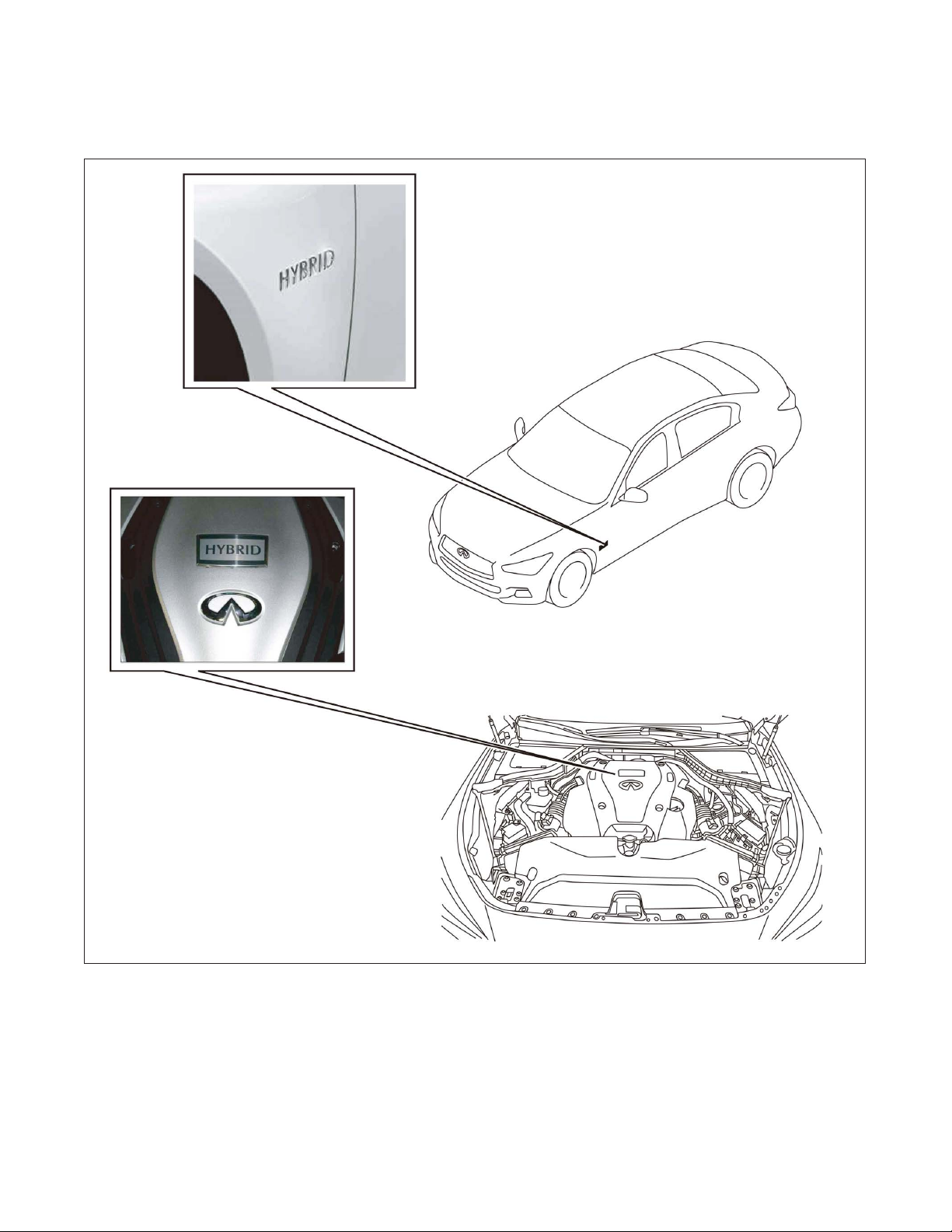
1-1 Q50 HYBRID IDENTIFICATION
1-1.1 Exterior and Engine Compartment
RAG–6
TGAAYIA0008ZZ
Page 7
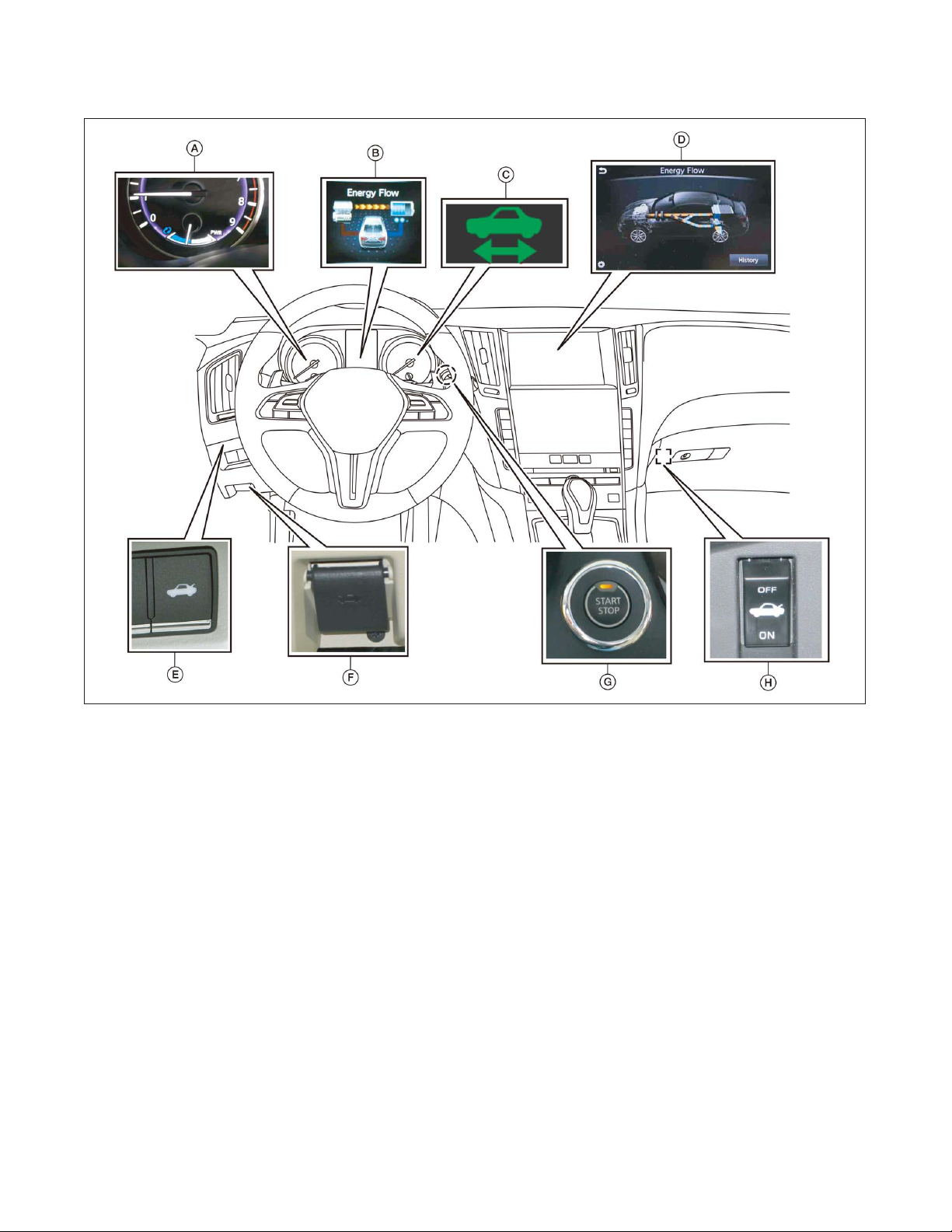
1-1.2 Interior
Interior components referenced in this manual are as follows:
TGAAYIA0003ZZ
A. Assist charge gauge B. Energy flow display *1 C. READY indicator (green)
D. Energy flow display *1 E. Trunk lid release switch F. Hood release handle
G. START/STOP switch and ON
indicator lamp (orange)
H. Trunk release power cancel
switch
*1: This screen may not be displayed due to customer settings.
RAG–7
Page 8
1-2 Vehicle Identification Number (VIN) Layout
In exterior appearance the Q50 HYBRID is nearly identical to the conventional Infiniti Q50 series vehicles.
The vehicle identification number can be located as follows:
Example VIN : JN1 AV7AP4JM690008
The Q50 HYBRID is identified by the 4th alphanumeric character: A
A = Q50 HYBRID
2
1. VIN plate (visible through windshield) 2. Chassis number
1
AAYIA0476ZZ
RAG–8
Page 9

1-3 Warning and Indicator Lamp Information
0
0
0
40
80
120
160
200
240
280
km/h
MPH
20
40
1
2
3
4
5
6
7
8
9
0
PWR
RPMx1000
60
80
100
120
140
160
180
1
1/2
1 2 3 4
Hybrid System Overheated
Stop Vehicle
Warning
AAYIA0179ZZ
1. Master Warning Lamp (Orange or Red) 2. Hybrid System Overheated Stop Vehicle Warning
(Vehicle Information Display)
3. Hybrid System Warning Lamp (Orange) 4. READY Indicator (Green)
Lamp Name Icon Description
READY Indicator
(Green)
Master Warning Lamp
(Orange or Red)
Hybrid System
Warning Lamp
(Orange)
This lamp is on when the high-voltage system is powered
up and the vehicle is ready to drive.
This lamp is on when another warning lamp or message is
displayed in the instrument cluster.
This lamp is on or blinking when:
• Malfunction has occurred in the hybrid control system
and/or
• High-voltage leak to vehicle chassis and/or
• Emergency shut-off system has been activated. The
shut-off system activates in the following conditions:
– Front and side collisions in which the air bags are
– Certain rear collisions.
deployed.
– Certain high-voltage system malfunctions.
RAG–9
Page 10
2. Basic High-voltage Information
2-1 Battery Information
The Q50 HYBRID utilizes two batteries in order to supply both high and low voltage.
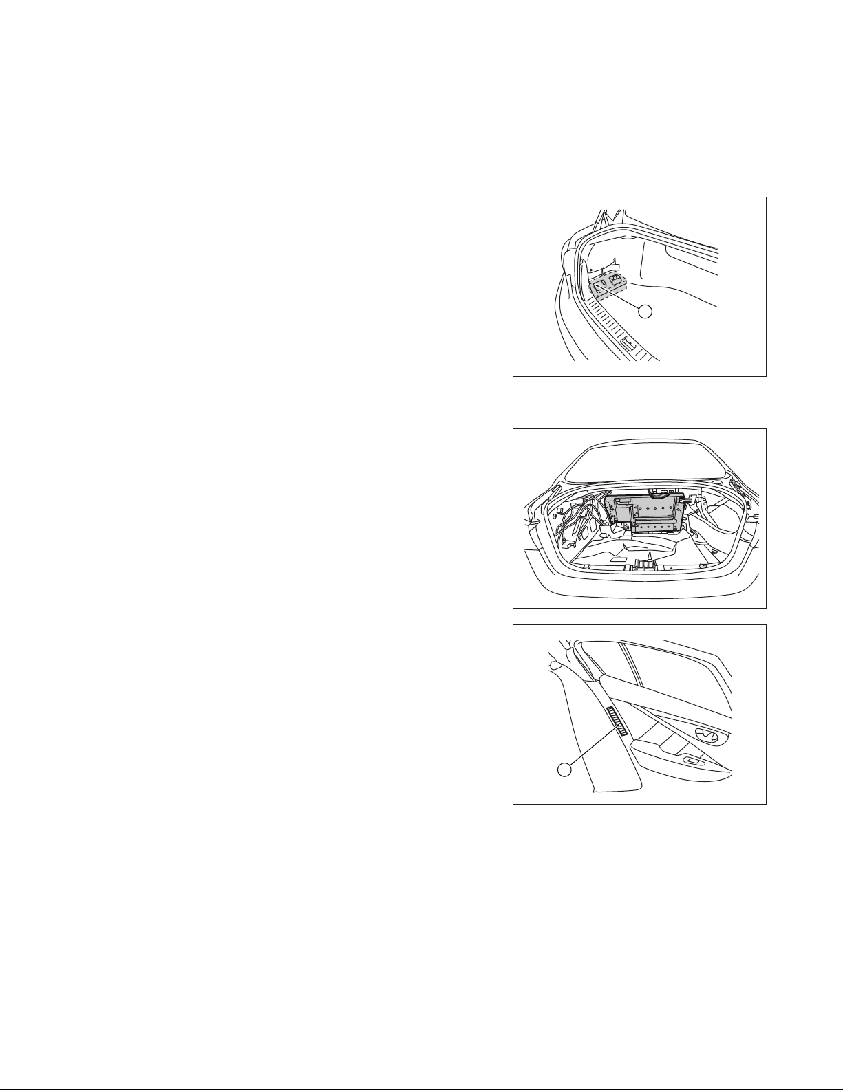
2-1.1 12-Volt Battery
• The Q50 HYBRID contains a conventional lead-acid
12-volt battery.
• The 12-volt battery is located in the trunk, on the left side,
concealed by a trim cover (A).
• The 12-volt battery is charged by the high-voltage battery
through the DC/DC converter.
2-1.2 High-voltage Battery
• The Q50 HYBRID contains a high-voltage battery.
• The high-voltage battery is mounted in the trunk area
behind the rear seat, enclosed in a metal case and
concealed by trim cover.
• The high-voltage battery stores energy at approximately
346 - 400 volts DC.
• A vent hose is provided to exhaust gasses outside the
vehicle if necessary.
A
AAYIA0180ZZ
• An air vent (A) is located on the rear left hand lower C-pillar
trim for battery cooling.
The high-voltage battery supplies power to the following:
• High-voltage harnesses
• DC/DC converter
• Traction motor inverter
• Traction motor
• Electric air conditioner compressor
AAYIA0183ZZ
A
AAYIA0184ZZ
RAG–10
Page 11

2-2 High-voltage-Related and 12-Volt-Related Component Locations and Descriptions
3 4
1
2
6
7
NOTE:
Components with white number in black background are high-voltage components.
No. Component Location Description
➊ Traction Motor
Inverter
Engine compartment
(right rear side)
Converts the DC power stored in the highvoltage battery to three-phase AC power and
controls motor torque (revolution) by regulating
the motor current. The inverter has a built in
high-voltage capacitor.
5
AAYIA0181ZZ
RAG–11
Page 12

No. Component Location Description
➋ Traction Motor Built-into the
transmission
High-voltage
Battery
➌
➍ Service Plug Trunk area (below
➄ 12-volt Battery Trunk area (left side
➏ High-voltage
➐ Electric Air Condi-
DC/DC Converter Trunk area (mounted
Harnesses
tioner Compressor
Trunk area (behind
rear seat back)
to top of highvoltage battery)
parcel shelf; behind
access door in trim
panel)
behind trim panel)
Trunk area (on high-
voltage battery),
under floor pan,
engine compartment
Engine compartment
(front driver side)
Converts three-phase alternating current (AC)
power to drive power (torque) which propels
the vehicle.
The high-voltage battery stores and outputs
DC power (Maximum voltage 400V) needed to
propel the vehicle.
The DC/DC converter reduces the voltage of
the high-voltage battery to provide power to
the 12-volt battery in order to operate the
vehicle’s electric components (headlights,
audio system, etc.).
This is used to disable the high-voltage system.
A lead-acid battery that supplies power to the
low voltage devices.
Orange-colored power cables carry high DC
voltage between each of the high-voltage
components.
Air conditioner compressor
2-3 High-voltage Battery Pack Specifications
High-voltage Battery Specifications
High-voltage battery voltage 346V (400V max.)
Number of high-voltage battery modules in the pack 12 modules (96 cells)
High-voltage battery module voltage 28.8V each
High-voltage battery dimensions 29.63 x 17.81 x 14.85 in.
(752.5 x 452.4 x 377.1 mm)
High-voltage battery weight 108.05 lbs (49 kg)
RAG–12
Page 13

2-4 High-voltage Safety Measures
Circuit insulation The high-voltage positive (+) and negative (-) circuits are insulated
from the metal chassis.
Reducing the risk of electrocution The high-voltage components and harnesses have insulated cases or
orange-colored coverings which provide insulation and easy
identification.
The high-voltage battery case is electrically connected to the vehicle
ground. This connection helps protect the vehicle occupants and
emergency responders from high-voltage electrical shock.
Identification The high-voltage components are labeled “WARNING” similar to the
label shown below. All high-voltage harnesses are coated in orange.
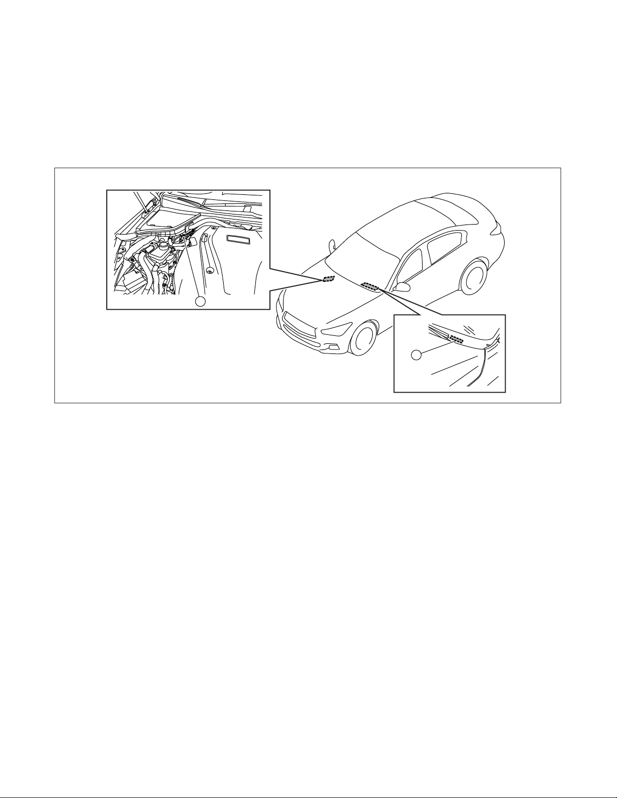
2-4.1 Warning Labels
The following labels are applied to the air duct located in the engine compartment.
WARNING/AVERTISSEMENT
To avoid serious injury, keep clear engine parts at all times. Engine may start at any time if the start switch and the the READY lamps
on the instrument panel are "ON". Make sure both lamps are "OFF" before working in the engine compartment. See Owners Manual.
Pour évi ter des bless ures graves, assurez-vous que les témoi ns START SWIT CH et READY d ans le tablea u de bord son t éteints
(OFF) avant d'entreprendre tout travail à I'intérieur du compartiment moteur. Le moteur peut démarrer à tout moment si le contacteur
d'allumage est à la position ON et que les témoins READY du tableau de bord sont allumés. Assurez-vous que les deux
témoins sont éteints avant de travailler dans le compartiment moteur. Reportez-vous au manuel du conducteur.
B
W AR NI N G/ AV E RT IS S EM EN T /A CH T UN G
Make sure READY lamp is "OFF" before working in the engine compartment.
Assurez-vous que les témoin READY est "OFF" avant de travailler dans le compartiment du moteur.
Bitte gehen Sie sicher, dass die READY-Kontrolleuchte "AUS" ist, bevor Sie jegliche Arbeit
im Motorraum beginnen.
D
AAYIA0419ZZ
RAG–13
Page 14

The following warning label is applied to the high-voltage battery located inside the luggage compartment
near the service plug access opening.
AAYIA0455ZZ
The following warning label is applied to the high-voltage battery located inside the luggage compartment.
AAYIA0456ZZ
RAG–14
Page 15

3. Roadside Assistance Response Steps
• NEVER assume the Q50 HYBRID is shut OFF simply because it is quiet.
•
• If the READY indicator is ON the high-voltage system is active.
• If possible, be sure to check the READY indicator on the instrument cluster and
• Some of the under hood parts get hot and may cause serious burns. Use caution when
If the vehicle is damaged and you are not sure about the condition of the electric
vehicle system, contact first responders immediately. If the vehicle is damaged, the
high-voltage system should be shut down by first responders while following the
procedures in the First Responders Guide and while wearing appropriate Personal
Protective Equipment (PPE).
verify that the READY indicator is OFF and the high-voltage system is stopped.
working on or around these parts.
3-1 Preparation Items
Preparation Items Specification Purpose
PPE (personal protective equipment): Up to 1,000V For protection from highInsulated gloves
voltage electrical shock.
Insulated shoes
–
Safety shield
Safety Glasses
Leather gloves Must be able to fasten tight
around the wrist. (Worn over
insulated gloves)
Wrenches
Size:10mm To remove the 12-volt battery
–
To protect eyes when around
high-voltage components and
wiring.
To protect insulated gloves.
terminal bolt.
RAG–15
Page 16

Preparation Items Specification Purpose
Solvent resistant protection gloves
Solvent resistant protection shoes –
Absorbent pad The same pad used for
internal combustion engine
fluids can be used.
Standard fire fighting equipment Standard fire fighting
equipment.
Depending on type of fire
(vehicle or battery) use
standard fire fighting
equipment (water or
extinguisher).
Insulated tape Insulating To cover any damaged
3-1.1 Personal Protective Equipment (PPE) Protective Wear Control
Perform an inspection of the Personal Protective Equipment (PPE) items before beginning work. Do not use
any damaged PPE items.
To utilize in the event of a
high-voltage battery
electrolytic solution leak.
To absorb any high-voltage
battery electrolytic solution
leakage.
To extinguish a fire.
harnesses to protect from and
prevent electrical shock. Tape
should cover all bare or
damaged wire.
3-1.2 Daily Inspection
This inspection is performed before and after use. The worker who will be using the items should perform
the inspection and check for deterioration and damage.
• Insulated rubber gloves should be inspected for scratches, holes and tears. (Visual check and air
leakage test)
• Insulated safety boots should be inspected for holes, damage, nails, metal pieces, wear or other
problems on the soles. (Visual check)
• Insulated rubber sheet should be inspected for tears. (Visual check)
3-1.3 Insulated Tools
When performing work at locations where high-voltage is applied (such as terminals), use insulated tools
meeting 1,000V/300A specifications.
3-2 Indications the High-voltage System is ON
If the READY
Before disconnecting the 12-volt battery terminal, if necessary, lower the windows, unlock the doors, and
open the rear hatch as required. Once 12-volt battery is disconnected, power controls will not operate.
indicator is ON, the high-voltage system is active.
RAG–16
Page 17

3-3 Vehicle Immobilization and Stabilization
If possible, immobilize the vehicle by turning the 12-volt system OFF and stabilize it with a wheel chock(s).
Stabilize the vehicle with wooden blocks or by removing air from the tires.
• To avoid electrical shock, do not put wooden blocks or wheel chock(s) under the
high-voltage components and harnesses as shown following.
AAYIA0185ZZ
RAG–17
Page 18

3-4 Turning OFF the Ignition Switch
1. Check the READY
indicator status. If it is ON, the high-voltage system is active.
2. Press the ignition switch once to turn OFF the highvoltage system. Then verify whether the READY
indicator is OFF.
3. If possible, keep the Infiniti Intelligent Key at least
5 meters (16 feet) away from the vehicle to prevent
accidentally turning ON the hybrid system while the
roadside assistance is in progress.
LOCK
ACC
(OFF)
ON
AAYIA0321ZZ
AAYIA0340ZZ
3-5 Water Submersion
DANGER
Damage level of submerged vehicle may not be apparent. Handling a submerged
vehicle without appropriate Personal Protective Equipment (PPE) will result in serious
injury or death from electrical shock.
• The ignition switch of the submerged vehicle must be turned OFF first, if possible.
Then the vehicle must be completely out of the water and drained to avoid electrical
shock.
• If the vehicle is in the water, to avoid electrical shock NEVER touch the high-voltage
components, harnesses or service plug. PPE must always be worn when touching or
working on high-voltage components.
Only first responders wearing appropriate Personal Protective Equipment (PPE) should shut down the
vehicle. After shut down, standard towing/recovery procedures can be used. Refer to
(RAG–24) .
4-3 Towing
RAG–18
Page 19

3-6 Vehicle Fire
• Always utilize full Personal Protective Equipment (PPE) and self-contained breathing
apparatus during fire fighting operations. Smoke from a Q50 HYBRID vehicle fire is
similar to smoke from a conventional vehicle fire.
• In the case of extinguishing a fire with water, large amounts of water from a fire hydrant
(if possible) must be used. DO NOT extinguish fire with a small amount of water.
In the event of a small fire, a Type ABC fire extinguisher may be used for an electrical fire
caused by wiring harnesses, electrical components, etc. or oil fire.
In case of vehicle fire, contact fire department immediately and extinguish the fire if possible. If you must
walk away from the vehicle, notify an appropriate responder or a rescue person of the fact that the vehicle is
a hybrid vehicle that contains a high-voltage system and warn all others.
3-7 High-voltage Battery Damage And Fluid Leaks
The high-voltage battery contains electrolyte solution. To avoid exposure to electrolyte
solution and serious personal injury, always wear appropriate solvent resistant Personal
Protective Equipment (PPE) and read the following precautions:
• Electrolyte solution is a skin irritant.
• Electrolyte solution is an eye irritant – If contact with eyes, rinse with plenty of water and
see a doctor immediately.
• If electrolyte leak occurs, wear appropriate solvent resistant PPE and use a dry cloth to
clean up the spilled electrolyte. Be sure to adequately ventilate the area.
• Electrolyte solution is highly flammable.
• Electrolyte liquid or fumes that have come into contact with water vapors in the air will
create an oxidized substance. This substance may irritate skin and eyes. In these cases,
rinse with plenty of water and see a doctor immediately.
• Electrolyte fumes (when inhaled) can cause respiratory irritation and acute intoxication.
Move to fresh air and wash mouth with water. See a doctor immediately.
In cases of battery case breach or electrolyte leakage, contact the fire department immediately. If you must
walk away from the vehicle, notify an appropriate responder of the fact that the vehicle is a hybrid vehicle
and contains a high-voltage system and warn all others.
High-voltage Battery Electrolyte Solution Characteristics:
• Clear in color
• Sweet odor
• Similar viscosity to water
• Since the high-voltage battery is made up of many small sealed battery modules, electrolyte solution
leakage should be minimal.
NOTE:
Other fluids in the vehicle (such as engine oil, washer fluid, brake fluid, coolant, etc.) are
the same as those in a conventional vehicle.
RAG–19
Page 20

4. Roadside Assistance
4-1 Jump Starting
To start the hybrid system with a booster battery, the instructions and precautions below must be followed.
If done incorrectly, jump starting can lead to a 12-volt battery explosion, resulting in severe
personal injury or death. It could also damage your vehicle.
Jump starting provides power to the 12-volt system to allow the electrical systems to operate. The electrical
systems must be operating to allow the high-voltage battery to be charged. Jump starting does not charge
the high-voltage battery.
Discharged 12-volt battery may cause the following issues:
• The instrument cluster cannot be displayed while the ignition switch is turned ON. (The hybrid
system cannot start.)
• Headlamps, horn, etc. are weak.
• To avoid electrical shock, the high-voltage battery CANNOT be jump started.
• Explosive hydrogen gas is always present in the vicinity of the 12-volt battery. Keep all
sparks and flames away from the 12-volt battery. Make sure the vent tube is mounted.
• Do not allow battery fluid to come into contact with eyes, skin, clothing or painted
surfaces. Battery fluid is a corrosive sulfuric acid solution that can cause severe burns.
If the fluid comes into contact with anything, immediately flush the contacted area
with water.
• The booster battery must be rated at 12 volts. Use of an improperly rated battery can
damage the vehicle.
• Whenever working on or near a 12-volt battery, always wear suitable eye protectors (for
example, goggles or industrial safety spectacles) and remove rings, metal bands, or any
other jewelry. Do not lean over the 12-volt battery when jump starting.
• Do not attempt to jump start a frozen battery. It could explode and cause serious injury.
• Q50 HYBRID is equipped with an automatic cooling fan. It could come on at any time.
Keep hands and other objects away from it.
• Always follow the jump starting instructions below. Failure to do so could result in
damage to the charging system and cause personal injury.
RAG–20
Page 21

4-1.1 Jump Starting Procedures
TGAAYIA0005ZZ
: Vehicle front
NOTE:
Jumper cable connections under the hood of the Q50 HYBRID are not connected directly to
a battery. They are connected to chassis ground and a fuse box terminal. Refer to the
following instructions and the above illustration.
1. If the booster battery is in another vehicle (A), position the two vehicles (A and B) to bring the
12-volt battery and fuse box into close proximity to each other.
DO NOT allow the two vehicles to touch.
2. Apply the parking brake. Move the selector lever the P (Park) position. Switch off all unnecessary
electrical systems (headlights, heater, air conditioner, etc.).
3. Remove fuse box cover on the Q50 HYBRID and connect jumper cables in the sequence as
illustrated (➀→➁→➂→➃).
For models with a steering wheel lock mechanism:
If the 12-volt battery is disconnected or discharged, the steering wheel will lock and cannot be
turned. Supply power using jumper cables before pushing the ignition switch and disengaging
the steering lock.
RAG–21
Page 22

• Always connect positive (+) to positive (+) and negative (-) to body ground (for example,
as illustrated), not to the 12-volt battery.
• Make sure the jumper cables do not touch moving parts in the engine compartment and
that the cable clamps do not contact any other metal.
• If the hybrid system does not start right away, push the ignition switch to the OFF
position and wait ten (10) seconds before trying again.
4. Start the engine of the booster vehicle (A) and let it run for a few minutes.
5. Start the hybrid system of the vehicle being jump started (B).
6. After starting the hybrid system, carefully disconnect the negative cable and then the positive
cable (➃→➂→➁→➀).
7. Reinstall the fuse box cover.
NOTE:
If it is not possible to turn the hybrid system ON by following this procedure, it is
recommended you contact an INFINITI retailer immediately.
4-1.2 Shift Selector Lever Lock Release
If the 12-volt battery is low or discharged, the selector lever cannot be moved from the Park (P) position. If a
booster battery is not available, the selector lever lock can be manually released. To manually release the
selector lever lock, perform the following procedure:
1. Push the ignition switch to the LOCK or OFF position.
2. Apply the parking brake.
3. Remove the shift lock cover (A) using a suitable tool.
4. Push down the shift lock (B) as shown in the illustration.
5. Push the selector lever button (C) and move the selector
lever to the Neutral (N) position (D) while holding down
the shift lock.
C
A
D
B
AAYIA0256ZZ
RAG–22
Page 23

4-2 Tools Installed in the Vehicle
Tools (if so equipped):
The tools are located in the trunk area.
• Raise the trunk floor cover (1).
• Remove jacking tools located inside the trunk as
illustrated.
1
AAYIA0417ZZ
Spare tire (if so equipped):
The spare tire is located under the trunk floor cover.
• Remove the clamp (2) holding the spare tire.
2
AAYIA0401ZZ
RAG–23
Page 24

4-3 Towing
4-3.1 Vehicle Specifications
Length 189.6 in. (4,815 mm) *1
189.1 in. (4,803 mm) *2
Width 71.8 in. (1,824 mm)
Overall Height 56.8 in. (1,443 mm) *3
57.2 in (1,453 mm) *4
Wheel Base 112.2 in. (2,850 mm)
Minimum ground clearance 5.1 in. (130.2 mm) *3
4.8 in. (122.0 mm) *4
Overall vehicle weight 1,826 kg – 1,904 kg (4,025 lbs. – 4,197 lbs.)
(Weight varies by equipment and trim level.)
Front approach angle 16.0˚ *3
16.6˚ *4
Rear departure angle 16.2˚ *3
16.8˚ *4
*1 With front license plate
*2 Without front license plate
*3: 2WD models
*4: AWD models
4-3.2 Towing Guidelines
Infiniti strongly recommends that Q50 HYBRID be towed with the driving (rear) wheels off the ground or
that a dolly be used as illustrated.
• Never tow with the rear wheels on the ground or four (4) wheels on the ground (forward
or backward), as this may cause serious and expensive damage to the motor.
• Never tow AWD models with any of the wheels on the ground as this may cause serious
and expensive damage to the powertrain.
• Transport the vehicle only after turning the ignition switch OFF.
• Safety chains or cables must be attached only to the main structural members of the
vehicle. Otherwise, the vehicle body will be damaged.
• Do not use the vehicle tie down hook to free a vehicle stuck in sand, snow, mud, etc.
• Never tow a vehicle using the vehicle tie down hook.
• Always pull the cable straight out from the front of the vehicle. Never pull on the vehicle
at an angle.
• Pulling devices should be routed so they do not touch any part of the suspension,
steering, brake, high-voltage or cooling systems.
• Pulling devices such as ropes or canvas straps are not recommended for use in vehicle
towing or recovery.
RAG–24
Page 25

Perform vehicle towing by holding up drive (rear) wheels or on flatbed in order to prevent secondary
damage from voltage generated by the motor. In addition, turn the ignition switch OFF when towing the
vehicle. Refer to the following illustrations:
2WD models
AAYIA0402ZZ
AWD models
AAYIA0414ZZ
NOTE:
It is also permissible to transport the Q50 facing rearward on a flatbed. If the vehicle cannot be
placed in Neutral, a P (Park) release procedure may be required. Refer to
4-1.2 Shift Selector
Lever Lock Release (RAG–22).
RAG–25
Page 26

4-3.3 Use of Vehicle Equipped Hooks for Recovery Operations
SAA
YIA0504ZZ
If the vehicle is stuck in sand, snow, mud, etc., use a tow strap or other device designed specifically for
vehicle recovery. Always follow the manufacturer’s instructions for the recovery device.
To avoid vehicle damage, serious personal injury or death when recovering a stuck vehicle:
• Tow chains or cables must be attached only to main structural members of the vehicle.
• Do not use the vehicle tie-downs to tow or free a stuck vehicle.
• Only use devices specifically designed for vehicle recovery and follow the manufacturer’s
instructions.
• Always pull the recovery device straight out from the front of the vehicle. Never pull at an
angle.
• Route recovery devices so they do not touch any part of the vehicle except the attachment
point.
Front Tie Down Hook:
• Do not use the front tie down hook for towing or vehicle
recovery.
Rear Tie Down Hook:
• Do not use the rear tie down hook for towing or vehicle
recovery.
• The rear tie down hook is designed to secure the vehicle
during transport only, as illustrated.
TGAAYIA0010ZZ
AAYIA0400ZZ
AAYIA0504ZZ
RAG–26
Page 27

4-4 Jacking Up the Vehicle and Changing a Tire
The Q50 is factory equipped with run-flat tires. It is not equipped with a jack or spare tire as standard
equipment. However, the following jacking instructions apply when using the optional Infiniti jack.
Always follow these instructions when jacking up the vehicle and changing a tire:
• Never change a tire when the vehicle is on a slope, ice or slippery areas. Jack must be on
level ground.
• Make sure the parking brake is securely applied and shift selector is in P (Park) position.
• Never get under the vehicle while it is supported only by the jack. If it is necessary to work
under the vehicle, support it with safety stands.
• Use the correct jack-up points. Never use any other part of the vehicle for jack support.
• Never jack up the vehicle more than necessary.
• Never use blocks on or under the jack.
• Do not start or run the engine while vehicle is on the jack. It may cause the vehicle to
move. This is especially true for vehicles with limited slip differentials.
• Do not allow passengers to stay in the vehicle while it is on the jack.
• Never run the engine with a wheel(s) off the ground. It may cause the vehicle to move.
• Be sure to block the wheel diagonally opposite the wheel being removed as the vehicle
may move and result in personal injury.
Failure to follow these instructions can result in serious personal injury or death and/or
vehicle damage.
1. Place the jack directly under the jack-up point as illustrated so the top of the jack contacts the
vehicle at the jack-up point. Align the jack head between the two notches in the front or the rear
as shown. Also fit the groove of the jack head between the notches as shown. The jack
should be used on level firm ground.
AAYIA0403ZZ
2. Loosen each wheel nut one or two turns by turning it counterclockwise with the wheel nut
wrench. Do not remove the wheel nuts until the tire is off the ground.
RAG–27
Page 28

3. To lift the vehicle, securely hold the jack lever and rod with both hands as shown. Carefully raise
the vehicle until the tire clears the ground. Remove the wheel nuts, and then remove the tire.
4. Install new or repaired tire and hand-tighten the wheel
nuts with the wheel nut wrench in an alternating pattern.
A
D
B
Always follow these instructions when changing a tire:
• Incorrect wheel nuts or improperly tightened wheel
C
E
nuts can cause the wheel to become loose or come
off. This could cause an accident.
• Do not use oil or grease on the wheel studs or nuts.
This could cause the nuts to become loose.
AAYIA0136ZZ
AAYIA0137ZZ
Failure to follow these instructions can result in serious
personal injury or death and/or vehicle damage.
5. Securely torque the wheel nuts in an alternating pattern to 80 ft-lb (108 Nm).
6. Lower the vehicle and remove the jack and securely store the flat tire, tools and jacking
equipment in the vehicle.
Always follow these instructions when using the jacking equipment or after changing a tire:
• Always make sure that the spare tire and jacking equipment are properly secured after
use. Such items can become dangerous projectiles in an accident or sudden stop.
Failure to follow these instructions can result in serious personal injury or death and/or
vehicle damage.
NOTE:
To help prevent squeaks and rattles, check that the tools are reinstalled and properly secured
in the stored place after use.
RAG–28
Page 29

5. Storing the Vehicle
The service plug must be removed to shut down the high-voltage system for storage.
Do not store a vehicle inside a structure. Keep the vehicle away from other vehicles if the
high-voltage battery is severely damaged. There is possibility of delayed fire from a severely
damaged high-voltage battery.
5-1 Danger Sign Example
If the Q50 HYBRID needs to be stored or left unattended, the high-voltage system must be shut down by
removing the service plug [refer to
indicating it is a hybrid vehicle with high-voltage dangers. For example:
5-2 Remove Service Plug (RAG–31)] and a sign put on the vehicle
RAG–29
Page 30

RAG–30
AAYIA0020GB
Page 31

5-2 Remove Service Plug
DANGER
• Do not remove the service plug without always wearing appropriate Personal
Protective Equipment (PPE) to help protect the responder from serious injury or death
by electrical shock.
• Immediately cover the service plug socket with insulated tape. The high-voltage
battery retains high-voltage power even when the service plug is removed. To avoid
electric shock, NEVER touch the terminals inside the socket.
To avoid unintended reinstallation and risk of electrical shock and severe personal injury
or death, the service plug should be securely stored away from the vehicle while the vehicle
is in storage.
NOTE:
Before disconnecting the 12-volt battery terminal, if necessary, lower the windows, adjust
the steering column, adjust the seats, unlock the doors, etc. Once 12-volt battery is
disconnected, power controls will not operate.
1. If possible, check the READY indicator status in the instrument cluster. If it is on, the highvoltage system is active.
2. Place the shift selector in the Park (P) position.
AAYIA0191ZZ
3. Push the ignition switch once to turn OFF the highvoltage system. Then verify whether the READY indicator
is off.
LOCK
(OFF)
ON
ACC
If the READY indicator does not turn off, continue to
step 4.
AAYIA0192ZZ
RAG–31
Page 32

4. If possible, keep the Infiniti Intelligent Key at least
5 meters (16 feet) away from the vehicle (except to open
the trunk as noted below).
5. Open the trunk using any of the following:
NOTE:
The trunk release power cancel switch must be in the
ON position in order for the trunk to be opened
using any of the methods below.
AAYIA0068ZZ
OFF
ON
a. push-button switch on the lower LH side of the
instrument panel.
b. trunk button on the Infiniti Intelligent Key [press
for longer than one (1) second].
AAYIA0203ZZ
AAYIA0068ZZ
RAG–32
Page 33

c. trunk open request switch (located above
license plate)*.
AAYIA0194ZZ
Method Shift Selector Position Ignition Switch Status
a P or N Any
b P OFF
c* Any Any
* You must have the Infiniti Intelligent Key within approximately 1 meter (3 feet) range of trunk request switch
to use the trunk open request switch function.
NOTE:
If the electrical release does not work, the trunk will have to be forced open.
6. Open the 12-volt battery service access cover.
7. Disconnect negative (-) battery cable and cover it with
insulated tape.
AAYIA0195ZZ
AAYIA0196ZZ
RAG–33
Page 34

8. Open service plug access cover.
AAYIA0204ZZ
9. Remove the service plug (A) by pulling the locking lever (B), then pressing the locking tab (C)
and rotating the handle (D) fully outward. Using the handle, pull the service plug (E) completely
out of its socket.
A
C
D
B
E
AAYIA0202ZZ
10. Cover the service plug socket with insulated tape.
11. Wait approximately ten (10) minutes for complete discharge of the high-voltage capacitor
after the service plug has been removed.
12. The vehicle is now ready for storage.
RAG–34
Page 35

© 2017 Nissan North America, Inc.
All rights reserved.
This document may not be altered without the written permission of Nissan North America, Inc.
Pub. No. RG18EAV37HU0
 Loading...