

Page 1
MAINTENANCE
GI
CONTENTS
PRECAUTIONS ...............................................................2
Precautions for Supplemental Restraint System
(SRS) ″AIR BAG″ and ″SEAT BELT
PRE-TENSIONER″......................................................2
PREPARATION ...............................................................3
Special Service Tool....................................................3
Commercial Service Tool.............................................3
GENERAL MAINTENANCE............................................4
PERIODIC MAINTENANCE ............................................6
Schedule 1...................................................................7
EMISSION CONTROL SYSTEM MAINTENANCE
CHASSIS AND BODY MAINTENANCE
Schedule 2...................................................................9
EMISSION CONTROL SYSTEM MAINTENANCE
CHASSIS AND BODY MAINTENANCE
RECOMMENDED FLUIDS AND LUBRICANTS...........11
Fluids and Lubricants ................................................11
SAE Viscosity Number ..............................................11
GASOLINE ENGINE OIL
Anti-freeze Coolant Mixture Ratio .............................12
ENGINE MAINTENANCE..............................................13
Checking Drive Belts.................................................13
Changing Engine Coolant..........................................14
- DRAINING ENGINE COOLANT -
- REFILLING ENGINE COOLANT -
- FLUSHING COOLING SYSTEM -
Checking Fuel Lines..................................................16
Changing Air Cleaner Filter .......................................17
VISCOUS PAPER TYPE
Changing Engine Oil..................................................17
..........................................11
...........................................17
........................8
......................10
............................14
...........................15
............................16
.........7
.........9
SECTION
Changing Oil Filter.....................................................18
Changing Spark Plugs...............................................18
Checking EVAP Vapor Lines.....................................20
CHASSIS AND BODY MAINTENANCE.......................21
Checking Exhaust System.........................................21
Checking A/T Fluid ....................................................21
Changing A/T Fluid....................................................22
Balancing Wheels (Bonding Weight Type)................22
REMOVAL
WHEEL BALANCE ADJUSTMENT
Tire Rotation..............................................................24
Checking Brake Fluid Level and Leaks.....................24
Checking Brake Lines and Cables............................24
Checking Disc Brake.................................................24
ROTOR
CALIPER
PAD
Checking Steering Gear and Linkage.......................25
STEERING GEAR
STEERING LINKAGE
Checking Power Steering Fluid and Lines................25
Lubricating Locks, Hinges and Hood Latches...........26
Checking Seat Belts, Buckles, Retractors,
Anchors and Adjusters...............................................26
SERVICE DATA AND SPECIFICATIONS (SDS).........27
Engine Maintenance..................................................27
BELT DEFLECTION AND TENSION
SPARK PLUG
Chassis and Body Maintenance................................27
WHEEL BALANCE
...............................................................22
...................................................................24
.................................................................25
........................................................................25
..........................................................27
MA
............................22
....................................................25
...............................................25
..........................27
...................................................27
EM
LC
EC
FE
AT
AX
SU
BR
ST
RS
BT
HA
SC
EL
IDX
Page 2

PRECAUTIONS
Precautions for Supplemental Restraint System (SRS) “AIR BAG” and “SEAT BELT PRE-TENSIONER”
Precautions for Supplemental Restraint System
(SRS) “AIR BAG” and “SEAT BELT
PRE-TENSIONER”
The Supplemental Restraint System such as “AIR BAG” and “SEAT BELTPRE-TENSIONER” used along with
a seat belt, helps to reduce the risk or severity of injury to the driver and front passenger for certain types of
collision. The SRS system composition which is available to INFINITI I30 is as follows (The composition varies according to optional equipment.):
I For a frontal collision
The Supplemental Restraint System consists of driver air bag module (located in the center of the steering wheel), front passenger air bag module (located on the instrument panel on passenger side), seat belt
pre-tensioners, a diagnosis sensor unit, crash zone sensor, warning lamp, wiring harness and spiral cable.
I For a side collision
The Supplemental Restraint System consists of front side air bag module (located in the outer side of front
seat), satellite sensor, diagnosis sensor unit (one of components of air bags for a frontal collision), wiring
harness, warning lamp (one of components of air bags for a frontal collision).
Information necessary to service the system safely is included in the RS section of this Service Manual.
WARNING:
I To avoid rendering the SRS inoperative, which could increase the risk of personal injury or death
in the event of a collision which would result in air bag inflation, all maintenance should be performed by an authorized INFINITI dealer.
I Improper maintenance, including incorrect removal and installation of the SRS, can lead to per-
sonal injury caused by unintentional activation of the system. For removal of Spiral Cable and Air
Bag Module, see the RS section.
I Do not use electrical test equipment on any circuit related to the SRS unless instructed to in this
Service Manual. SRS wiring harnesses can be identified with yellow harness connector (and with
yellow harness protector or yellow insulation tape before the harness connectors).
NHMA0034
MA-2
Page 3
PREPARATION
Special Service Tool
Special Service Tool
The actual shapes of Kent-Moore tools may differ from those of special service tools illustrated here.
Tool number
(Kent-Moore No.)
Tool name
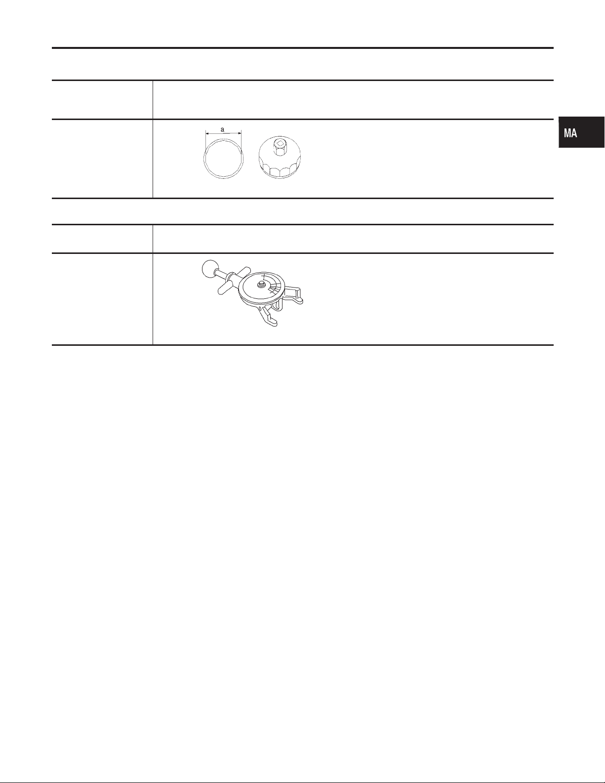
KV10115801
(J38956)
Oil filter cap wrench
Description
Removing oil filter
a: 64.3 mm (2.531 in)
NT375
Commercial Service Tool
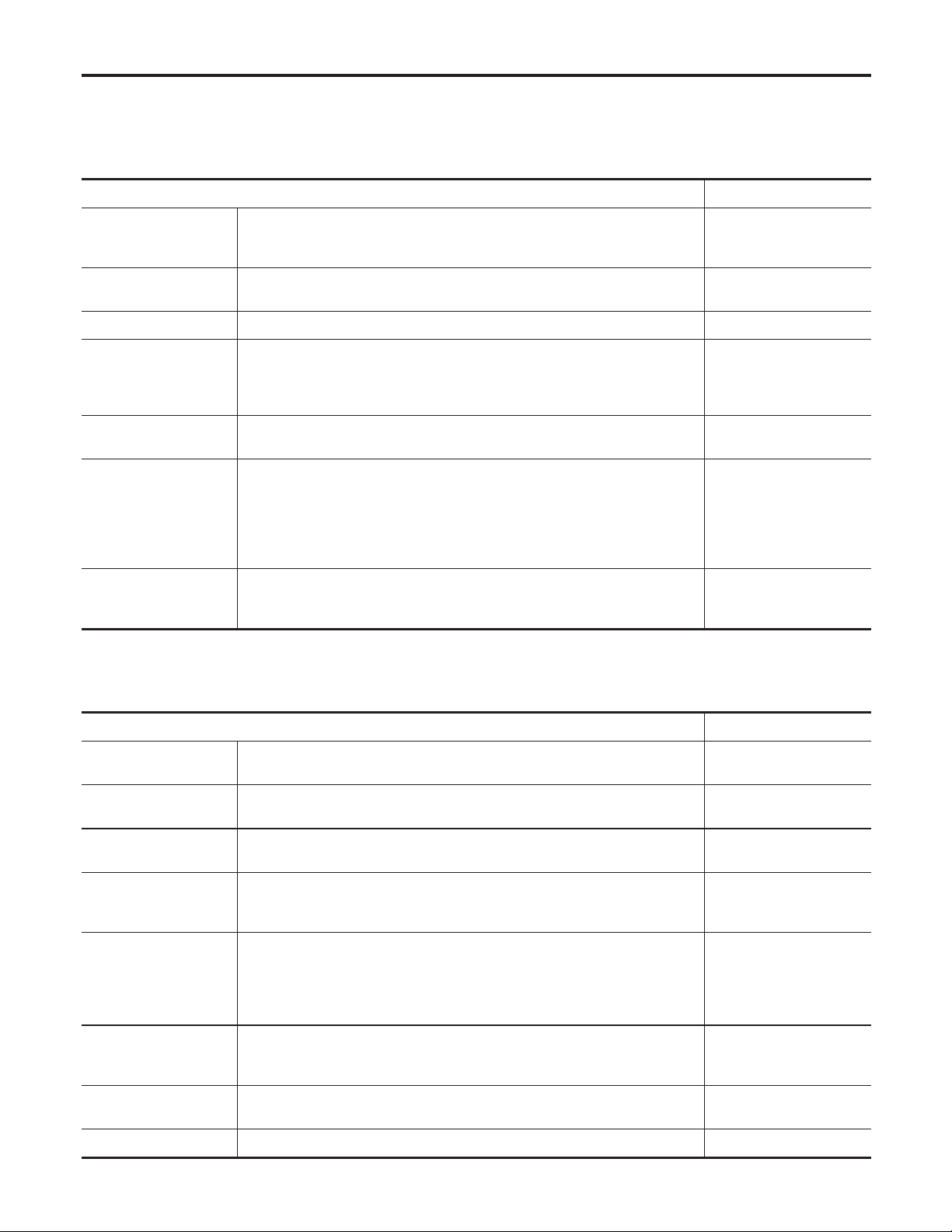
Tool name
(Kent-Moore No.)
Belt tension gauge
(BT3373-F)
Description
Checking drive belt tension
AMA126
NHMA0002
GI
EM
LC
NHMA0003
EC
FE
AT
AX
SU
BR
ST
RS
BT
HA
SC
EL
IDX
MA-3
Page 4
NHMA0004
GENERAL MAINTENANCE
General maintenance includes those items which should be checked during the normal day-to-day operation
of the vehicle. They are essential if the vehicle is to continue operating properly. The owners can perform
checks and inspections themselves or have their INFINITI dealers do them.
OUTSIDE THE VEHICLE
The maintenance items listed here should be performed from time to time, unless otherwise specified.
Item Reference page
Tires Check the pressure with a gauge periodically when at a service station,
including the spare, and adjust to the specified pressure if necessary. Check
carefully for damage, cuts or excessive wear.
—
Wheel nuts When checking the tires, make sure no nuts are missing, and check for any
loose nuts. Tighten if necessary.
Tire rotation Tires should be rotated every 12,000 km (7,500 miles). MA-24
Wheel alignment and
balance
Windshield wiper
blades
Doors and engine
hood
Lamps Make sure that the headlamps, stop lamps, tail lamps, turn signal lamps, and
If the vehicle pulls to either side while driving on a straight and level road, or
if you detect uneven or abnormal tire wear, there may be a need for wheel
alignment. If the steering wheel or seat vibrates at normal highway speeds,
wheel balancing may be needed.
Check for cracks or wear if they do not wipe properly. —
Check that all doors and the engine hood operate smoothly as well as the
trunk lid and back hatch. Also make sure that all latches lock securely. Lubricate if necessary. Make sure that the secondary latch keeps the hood from
opening when the primary latch is released.
When driving in areas using road salt or other corrosive materials, check
lubrication frequently.
other lamps are all operating properly and installed securely. Also check
headlamp aim.
SU-7, “Preliminary
—
MA-22,
Inspection”
MA-26
—
INSIDE THE VEHICLE
The maintenance items listed here should be checked on a regular basis, such as when performing periodic maintenance, cleaning the
vehicle, etc.
Item Reference page
Warning lamps and
chimes
Windshield wiper and
washer
Windshield defroster Check that the air comes out of the defroster outlets properly and in suffi-
Steering wheel Check that it has the specified play. Be sure to check for changes in the
Seats Check seat position controls such as seat adjusters, seatback recliner, etc. to
Seat belts Check that all parts of the seat belt system (e.g. buckles, anchors, adjusters
Accelerator pedal Check the pedal for smooth operation and make sure the pedal does not
Brakes Check that the brake does not pull the vehicle to one side when applied. —
Make sure that all warning lamps and chimes are operating properly. —
Check that the wipers and washer operate properly and that the wipers do
not streak.
cient quantity when operating the heater or air conditioner.
steering condition, such as excessive play, hard steering or strange noises.
Free play: Less than 35 mm (1.38 in)
make sure they operate smoothly and that all latches lock securely in every
position. Check that the head restrains move up and down smoothly and that
the locks (if equipped) hold securely in all latched positions. Check that the
latches lock securely for folding-down rear seatbacks.
and retractors) operate properly and smoothly and are installed securely.
Check the belt webbing for cuts, fraying, wear or damage.
catch or require uneven effort. Keep the floor mats away from the pedal.
RS-9, “Seat Belt
—
—
—
—
MA-26
Inspection”
—
MA-4
Page 5
GENERAL MAINTENANCE
Item Reference page
Brake pedal and
booster
Parking brake Check that the lever has the proper travel and make sure that the vehicle is
Automatic transaxle
“Park” mechanism
Check the pedal for smooth operation and make sure it has the proper distance under it when depressed fully. Check the brake booster function. Be
sure to keep floor mats away from the pedal.
held securely on a fairly steep hill when only the parking brake is applied.
Check that the lock release button on the selector lever operates properly
and smoothly. On a fairly steep hill check that the vehicle is held securely
with the selector lever in the “P” position without applying any brakes.
BR-13, “Brake Pedal
and Bracket” and
BR-21, “Brake Booster”
BR-37, “Parking Brake
Control”
—
UNDER THE HOOD AND VEHICLE
The maintenance items listed here should be checked periodically (e.g. each time you check the engine oil or refuel).
Item Reference page
Windshield washer
fluid
Engine coolant level Check the coolant level when the engine is cold. MA-15
Radiator and hoses Check the front of the radiator and clean off any dirt, insects, leaves, etc.,
Brake fluid level Make sure that the brake fluid level is between the “MAX” and “MIN” lines on
Battery Check the fluid level in each cell. It should be between the “MAX” and “MIN”
Check that there is adequate fluid in the tank. —
that may have accumulated. Make sure the hoses have no cracks,
deformation, deterioration or loose connections.
the reservoir.
lines.
—
MA-24
—
GI
EM
LC
EC
FE
AT
AX
SU
Engine drive belts Make sure that no belt is frayed, worn, cracked or oily. MA-13
Engine oil level Check the level on the dipstick after parking the vehicle on a level spot and
turning off the engine.
Power steering fluid
level and lines
Automatic transaxle
fluid level
Exhaust system Make sure there are no loose supports, cracks or holes. If the sound of the
Underbody The underbody is frequently exposed to corrosive substances such as those
Fluid leaks Check under the vehicle for fuel, oil, water or other fluid leaks after the
Check the level on the dipstick with the engine off. Check the lines for
improper attachment, leaks, cracks, etc.
Check the level on the dipstick after putting the selector lever in “P” with the
engine idling.
exhaust seems unusual or there is a smell of exhaust fumes, immediately
locate the trouble and correct it.
used on icy roads or to control dust. It is very important to remove these
substances, otherwise rust will form on the floor pan, frame, fuel lines and
around the exhaust system. At the end of winter, the underbody should be
thoroughly flushed with plain water, being careful to clean those areas where
mud and dirt can easily accumulate.
vehicle has been parked for a while. Water dripping from the air conditioner
after use is normal. If you should notice any leaks or gasoline fumes are
evident, check for the cause and correct it immediately.
MA-17
MA-25
MA-21
MA-21
—
—
BR
ST
RS
BT
HA
SC
EL
IDX
MA-5
Page 6
NHMA0005
PERIODIC MAINTENANCE
Two different maintenance schedules are provided, and should be used, depending upon the conditions in
which the vehicle is mainly operated. After 60,000 miles (96,000 km) or 48 months, continue the periodic
maintenance at the same mileage/time intervals.
Schedule 1
Schedule 2
Follow Periodic Maintenance Schedule 1 if the driving habits frequently
include one or more of the following driving conditions:
I Repeated short trips of less than 5 miles (8 km).
I Repeated short trips of less than 10 miles (16 km) with outside tempera-
tures remaining below freezing.
I Operating in hot weather in stop-and-go “rush hour” traffic.
I Extensive idling and/or low speed driving for long distances, such as
police, taxi or door-to-door delivery use.
I Driving in dusty conditions.
I Driving on rough, muddy, or salt spread roads.
I Towing a trailer, using a camper or a car-top carrier.
Follow Periodic Maintenance Schedule 2 if none of driving conditions shown
in Schedule 1 apply to the driving habits.
Emission Control
System Maintenance
Chassis and Body
Maintenance
Emission Control
System Maintenance
Chassis and Body
Maintenance
MA-7
MA-8
MA-9
MA-10
MA-6
Page 7
PERIODIC MAINTENANCE
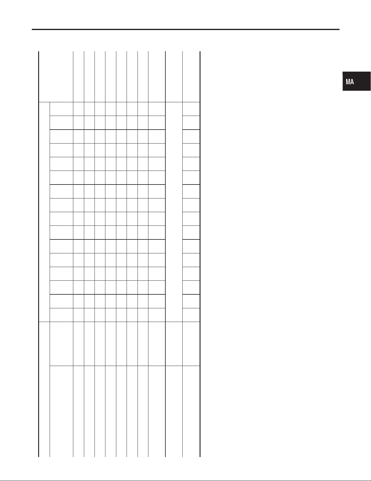
Schedule 1
Schedule 1
EMISSION CONTROL SYSTEM MAINTENANCE
or
- Page
60
56.3
52.5
48.8
45
41.3
37.5
33.8
- Content Title
(96)
(90)
(84)
(78)
(72)
(66)
(60)
(54)
48
45
42
39
36
33
30
27
Reference Section
NHMA0005S01
NHMA0005S0101
GI
Clearance”
EM-51, “Valve
EM
LC
EC
FE
AT
AX
Abbreviations: R = Replace. I = Inspect. Correct or replace if necessary. [ ]: At the mileage intervals only
30
(48)
(42)
26.3
(36)
22.5
(30)
18.8
15
(24)
(18)
11.3
7.5
(12)
(6)
3.8
(km x 1,000)
Miles x 1,000
24
21
18
15
12
9
6
3
Months
SU
BR
Replace every 105,000 miles (169,000 km). MA-18
ST
RS
BT
RRRRRRRRRRRRRRRR MA-18
HA
SC
EL
IDX
MAINTENANCE OPERATION MAINTENANCE INTERVAL
Perform at number of miles, kilome-
ters or months, whichever comes
first.
Drive belts NOTE (1) I* MA-13
Air cleaner filter NOTE (2) [R] [R] MA-17
EVAP vapor lines I* I* MA-20
Fuel lines I* I* MA-16
Fuel filter NOTE (3)
Engine coolant NOTE (4) R* MA-15
Engine oil RRRRRRRRRRRRRRRR MA-17
Engine oil filter (Use part No. 15208-
31U00 or equivalent.)
Spark plugs (PLATINUM-TIPPED
type)
Intake & exhaust valve clearance* NOTE (5)
MA-7
NOTE:
(1) After 60,000 miles (96,000 km) or 48 months, inspect every 15,000 miles (24,000 km) or 12 months.
(2) If operating mainly in dusty conditions, more frequent maintenance may be required.
(3) Maintenance-free item. For service procedures, refer to FE section.
(4) After 60,000 miles (96,000 km) or 48 months, replace every 30,000 miles (48,000 km) or 24 months.
(5) If valve noise increases, inspect valve clearance.
★ Maintenance items and intervals with “*” are recommended by INFINITI for reliable vehicle operation. The owner need not perform such maintenance in order to maintain the
emission warranty or manufacturer recall liability. Other maintenance items and intervals are required.
Page 8
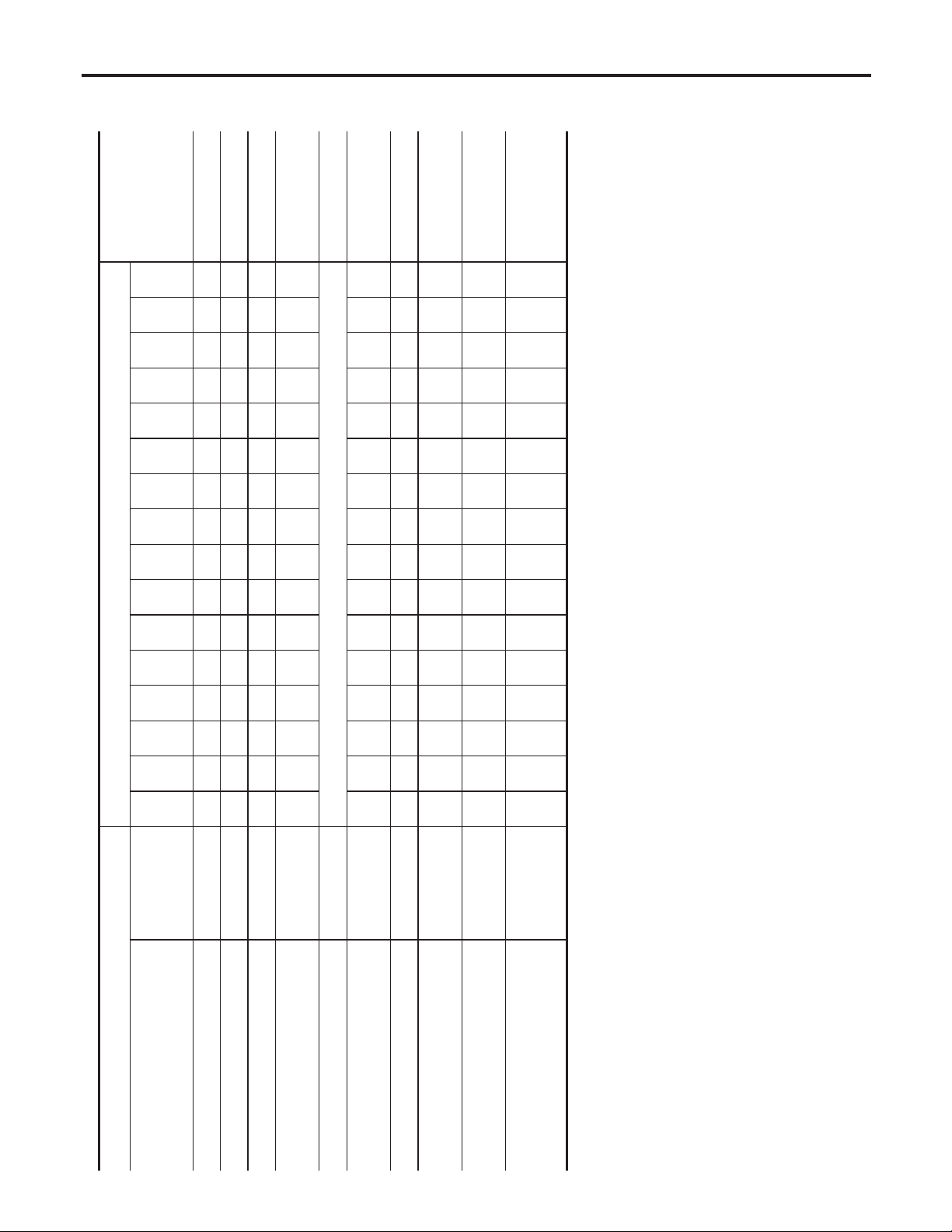
Schedule 1 (Cont’d)
PERIODIC MAINTENANCE
CHASSIS AND BODY MAINTENANCE
Abbreviations: R = Replace, I = Inspect. Correct or replace if necessary.
or
- Page
Section
Reference
60
(96)
(90)
56.3
(84)
52.5
(78)
48.8
45
(72)
(66)
41.3
(60)
37.5
(54)
33.8
30
(48)
- Content Title
48
45
42
39
36
33
30
27
24
MA-25
NOTE (3)
SHAFT”
AX-4, “DRIVE
nance Items”
RS-19, “Mainte-
tion Air Filter”
HA-123, “Ventila-
CHECK”
EL-297, “ASCD
ACTUATOR/PUMP
NHMA0005S0102
(42)
26.3
(36)
22.5
(30)
18.8
15
(24)
(18)
11.3
7.5
(12)
(6)
3.8
(km x 1,000)
Miles x 1,000
21
18
15
12
9
6
3
Months
IIIIIIII
NOTE (2)
Tire rotation NOTE (4) MA-4
Front drive shaft boots IIIIIIII
Exhaust system IIIIIIIIMA-21
Supplemental air bag system and
supplemental side air bag systems
Brake lines & cables IIIIMA-24
Brake pads & rotors IIIIIIIIMA-24
Automatic transaxle fluid NOTE (1) IIIIMA-21
Steering gear & linkage, axle & sus-
MAINTENANCE OPERATION MAINTENANCE INTERVAL
Perform at number of miles, kilome-
ters or months, whichever comes
first.
pension parts
Ventilation air filter IRIRIRIR
ASCD vacuum hoses IIII
NOTE:
(1) If towing a trailer, using a camper or a car-top carrier, or driving on rough or muddy roads, change (not just inspect) oil at every 30,000 miles (48,000 km) or 24 months.
(2) Inspect the supplemental air bag systems 10 years after the date of manufacture noted on the FMVSS certification label.
(3) Refer to SU-6, “Front Suspention Parts”, SU-19, “Rear Suspention Parts”, AX-3, “Front Axle Parts” and AX-18, “Rear Axle Parts”.
(4) Refer to “Tire rotation” under the “General maintenance” heading earlier in this section.
MA-8
Page 9
PERIODIC MAINTENANCE
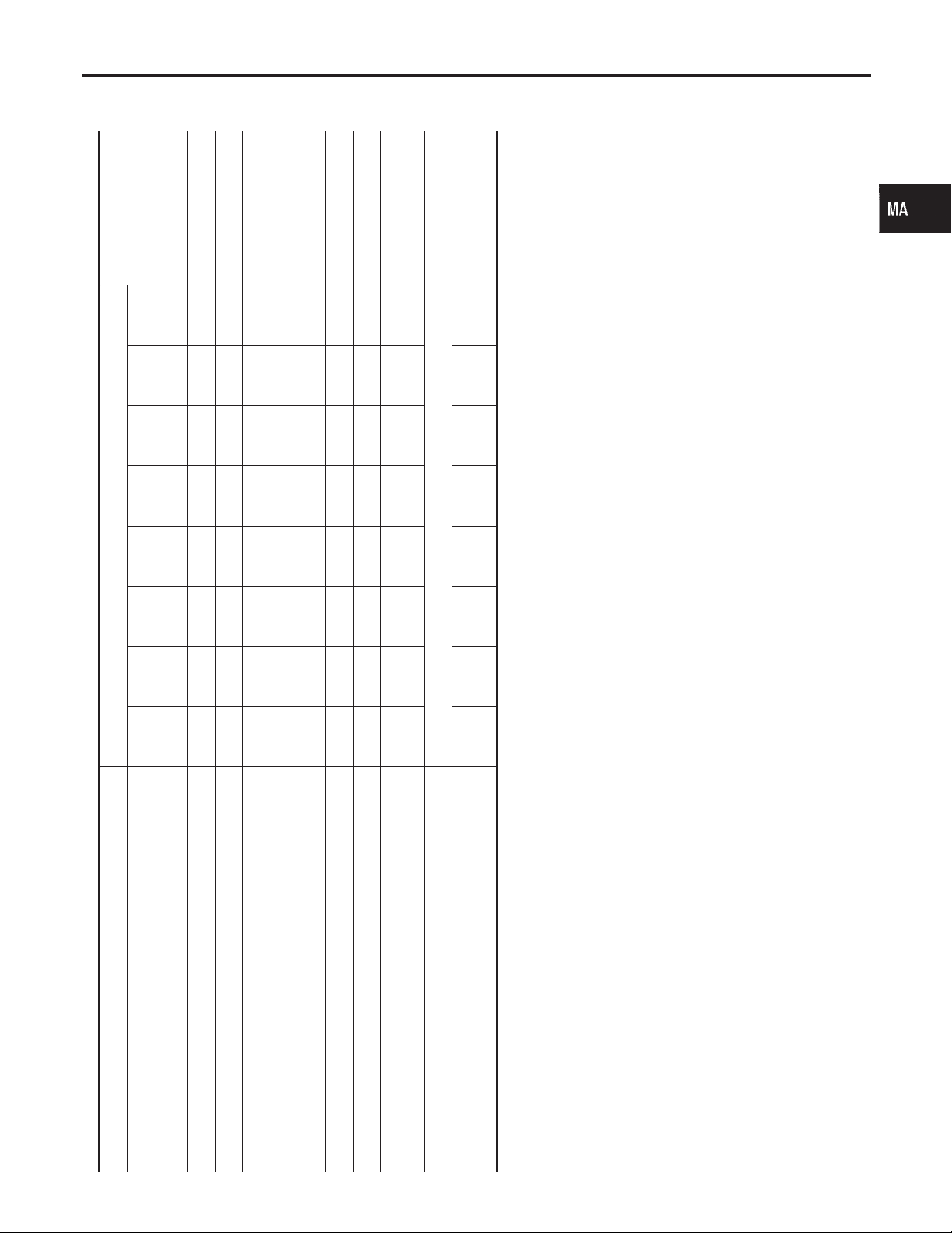
Schedule 2
Schedule 2
EMISSION CONTROL SYSTEM MAINTENANCE
or
- Page
60
52.5
45
37.5
- Content Title
(96)
(84)
(72)
(60)
48
42
36
30
Reference Section
ance”
EM-51, “Valve Clear-
NHMA0005S02
NHMA0005S0201
GI
EM
LC
EC
FE
AT
AX
Abbreviations: R = Replace. I = Inspect. Correct or replace if necessary. [ ]: At the mileage intervals only
30
(48)
(36)
22.5
15
(24)
7.5
(12)
(km x 1,000)
Miles x 1,000
24
18
12
6
Months
RRRRRRRR MA-18
SU
BR
ST
RS
BT
HA
SC
EL
IDX
MAINTENANCE OPERATION MAINTENANCE INTERVAL
Perform at number of miles, kilometers
or months, whichever comes first.
Drive belts NOTE (1) I* MA-13
Air cleaner filter [R] [R] MA-17
EVAP vapor lines I* I* MA-20
Fuel lines I* I* MA-16
Fuel filter NOTE (2)
Engine coolant NOTE (3) R* MA-15
Engine oil RRRRRRRR MA-17
Engine oil filter (Use part No. 15208-
31U00 or equivalent.)
Spark plugs (PLATINUM-TIPPED type) Replace every 105,000 miles (169,000 km). MA-18
MA-9
Intake & exhaust valve clearance* NOTE (4)
NOTE:
(1) After 60,000 miles (96,000 km) or 48 months, inspect every 15,000 miles (24,000 km) or 12 months.
(2) Maintenance-free item. For service procedures, refer to FE section.
(3) After 60,000 miles (96,000 km) or 48 months, replace every 30,000 miles (48,000 km) or 24 months.
(4) If valve noise increases, inspect valve clearance.
★ Maintenance items and intervals with “*” are recommended by INFINITI for reliable vehicle operation. The owner need not perform such maintenance in order to maintain the
emission warranty or manufacturer recall liability. Other maintenance items and intervals are required.
Page 10

Schedule 2 (Cont’d)
PERIODIC MAINTENANCE
CHASSIS AND BODY MAINTENANCE
- Page
Reference Section
60
52.5
45
37.5
or
- Content Title
(96)
(84)
(72)
(60)
48
42
36
30
MA-25
NOTE (2)
Filter”
Items”
RS-19, “Maintenance
HA-123, “Ventilation Air
CHECK”
EL-297, “ASCD
ACTUATOR/PUMP
NHMA0005S0202
Abbreviations: R = Replace, I = Inspect. Correct or replace if necessary.
30
(48)
(36)
22.5
15
(24)
7.5
(12)
(km x 1,000)
Miles x 1,000
24
18
12
6
Months
II
NOTE (1)
MAINTENANCE OPERATION MAINTENANCE INTERVAL
Perform at number of miles, kilometers
or months, whichever comes first.
Brake lines & cables IIIIMA-24
Brake pads & rotors IIIIMA-24
Automatic transaxle fluid IIIIMA-21
Steering gear & linkage, axle & suspen-
sion parts
Tire rotation NOTE (3) MA-4
Front drive shaft boots IIIIAX-4, “Drive Shaft”
Exhaust system I I MA-21
Supplemental air bag system and
supplemental side iar bag systems
Ventilation air filter RRRR
ASCD vacuum hoses IIII
NOTE:
(1) Inspect the supplemental air bag systems 10 years after the date of manufacture noted on the FMVSS certification label.
(2) Refer to SU-6, “Front Suspention Parts”, SU-19, “Rear Suspension Parts”, AX-3, “Front Axle Parts” and AX-18, “Rear Axle Parts”.
(3) Refer to “Tire rotation” under the “General maintenance” heading earlier in this section.
MA-10
Page 11

RECOMMENDED FLUIDS AND LUBRICANTS
NHMA0006
Fluids and Lubricants
Fluids and Lubricants
Capacity (Approximate)
US measure Imp measure Liter
With oil filter
Engine oil
Drain and refill
Dry engine (engine overhaul) 5-1/8 qt 4-1/4 qt 4.8
Cooling system
Automatic transaxle fluid
Power steering fluid — — — Genuine NISSAN PSF II or equivalent*4
Brake fluid — — —
Multi-purpose grease — — — NLGI No. 2 (Lithium soap base)
*1: For further details, see “SAE Viscosity Number”.
*2: Dexron
ership for more information regarding suitable fluids, including recommended brand(s) of Dexron
sion Fluid.
*3: Available in mainland U.S.A. through your INFINITI dealer.
*4: Genuine Nissan PSF, Canada NISSAN Automatic Transmission Fluid, Dexron
TM
change
Without oil filter
change
With reservoir 8-1/8 qt 6-3/4 qt 7.7
Reservoir 3/4 qt 5/8 qt 0.7
RE4F04B/
RE4F04W
III/MerconTMor equivalent may also be used. Outside the continental United States and Alaska contact an INFINITI deal-
4-1/4 qt 3-1/2 qt 4.0
3-7/8 qt 3-1/4 qt 3.7
10 qt 8-1/4 qt 9.4
TM
III/MerconTM, or equivalent ATF may also be used.
Recommended Fluids/Lubricants
I API Certification Mark*1
I API grade SG/SH, Energy Conserving I &
II or API grade SJ, Energy Conserving*1
I ILSAC grade GF-I & GF-II*1
Genuine Nissan Anti-freeze coolant or
equivalent
Nissan Matic “D” (Continental U.S. and
Alaska) or Canada NISSAN Automatic Transmission Fluid*2
Genuine Nissan Brake Fluid*3 or equivalent
DOT 3 (US FMVSS No. 116)
TM
III/MerconTMAutomatic Transmis-
NHMA0006S01
GI
EM
LC
EC
FE
AT
AX
SU
SAE Viscosity Number
GASOLINE ENGINE OIL
NHMA0006S02
NHMA0006S0203
SAE 5W-30 viscosity oil is preferred for all temperatures. SAE
10W-30 and 10W-40 viscosity oil may be used if the ambient temperature is above −18°C (0°F).
BR
ST
RS
BT
HA
SC
EL
IDX
MMA117AA
MA-11
Page 12

RECOMMENDED FLUIDS AND LUBRICANTS
Anti-freeze Coolant Mixture Ratio
SMA947CA
Anti-freeze Coolant Mixture Ratio
NHMA0006S03
The engine cooling system is filled at the factory with a high-quality,
year-round, anti-freeze coolant solution. The anti-freeze solution
contains rust and corrosion inhibitors. Therefore, additional cooling
system additives are not necessary.
CAUTION:
When adding or replacing coolant, be sure to use only Genuine Nissan anti-freeze coolant or equivalent with the proper
mixture ratio of 50% anti-freeze and 50% demineralized water/
distilled water.
Other types of coolant solutions may damage your cooling
system.
MA-12
Page 13

ENGINE MAINTENANCE
Checking Drive Belts
Checking Drive Belts
NHMA0007
GI
EM
LC
EC
FE
AT
AX
Belt deflection and tension:
With air conditioner compressor
Alternator
Without air conditioner compressor
Limit
7 (0.28)
10 (0.39)
1. Inspect belts for cracks, fraying, wear and oil. If necessary,
replace.
2. Inspect drive belt deflection or tension at a point on the belt
midway between pulleys.
I Check belt tension using belt tension gauge (BT 3373-F or
equivalent).
I Inspect drive belt deflection or tension when engine is
cold.
Adjust if belt deflection exceeds the limit or if belt tension is
not within specifications.
I Drive belt tension can also be checked at other points on
the belts.
Deflection adjustment
Unit: mm (in)
Used belt
After adjust-
ment
4.2 - 4.6
(0.165 - 0.181)
6.3 - 6.9
(0.248 - 0.272)
New belt
3.7 - 4.1
(0.146 - 0.161)
5.6 - 6.0
(0.220 - 0.236)
Used belt
Limit
294 (30, 66)
294 (30, 66)
Tension adjustment*1
Unit: N (kg, lb)
After adjust-
ment
730 - 818
(74.5 - 83.5,
164 - 184)
730 - 818
(74.5 - 83.5,
164 - 184)
SU
SMA804CB
BR
ST
RS
BT
HA
SC
EL
New belt
IDX
838 - 926
(85.45 - 94.43,
188.4 - 208.2)
838 - 926
(85.45 - 94.43,
188.4 - 208.2)
MA-13
Page 14

Checking Drive Belts (Cont’d)
ENGINE MAINTENANCE
Deflection adjustment
Unit: mm (in)
Used belt
Limit
Power steering oil pump 11 (0.43)
Applied pushing force 98 N (10 kg, 22 lb) —
*1: If the belt tension gauge cannot be installed at check points shown, check drive belt tension at a different location on the belt.
After adjust-
ment
7.3 - 8 (0.287 -
0.315)
New belt
6.5 - 7.2
(0.256 - 0.283)
Limit
196 (20, 44)
Changing Engine Coolant
Tension adjustment*1
Unit: N (kg, lb)
Used belt
After adjust-
ment
495 - 583
(50.5 - 59.5,
111 - 131)
New belt
603 - 691
(61.5 - 70.5,
136 - 155)
NHMA0008
WARNING:
To avoid the danger of being scalded, never change the coolant when the engine is hot.
SMA032D
SMA033D
— DRAINING ENGINE COOLANT —
NHMA0008S01
1. Set air conditioning system as follows to prevent coolant from
remaining in the system.
a. Turn ignition switch ON and set temperature controller to maxi-
mum hot position.
b. Wait 10 seconds before turning ignition switch OFF.
2. Open radiator drain plug at the bottom of radiator, and remove
radiator filler cap.
3. Remove reservoir tank, drain coolant, then clean reservoir
tank.
I Be careful not to allow coolant to contact drive belts.
MA-14
Page 15

ENGINE MAINTENANCE
4. Remove drain plugs on both sides of cylinder block and air
relief plug.
5. Check drained coolant for contaminants such as rust, corrosion or discoloration. If contaminated flush engine cooling
system, refer to “FLUSHING COOLING SYSTEM”, MA-16.
SMA034D
Changing Engine Coolant (Cont’d)
GI
EM
LC
EC
FE
AT
SMA953CA
— REFILLING ENGINE COOLANT —
1. Install reservoir tank, and radiator drain plug.
2. Close and tighten cylinder block drain plugs securely.
I Apply sealant to the thread of cylinder block drain plugs.
: 60 - 66 N·m (6.1 - 6.7 kg-m, 44 - 48 ft-lb) Left side
: 18 - 22 N·m (1.8 - 2.2 kg-m, 13 - 16 ft-lb) Right side
3. Fill radiator slowly with coolant until coolant spills from the air
relief plug, then install air relief plug.
Air relief plug:
: 6.9 - 7.8 N·m (0.7 - 0.8 kg-m, 61 - 69 in-lb)
I Use genuine Nissan anti-freeze coolant or equivalent
mixed with water (distilled or demineralized).
NHMA0008S02
AX
SU
BR
ST
RS
BT
HA
SC
EL
IDX
MA-15
Page 16

Changing Engine Coolant (Cont’d)
ENGINE MAINTENANCE
Refer to “RECOMMENDED FLUIDS AND LUBRICANTS”,
MA-11.
Engine coolant capacity (With reservoir tank):
7.7 (8-1/8 US qt, 6-3/4 Imp qt)
Reservoir tank capacity:
0.7 (3/4 US qt, 5/8 Imp qt)
I Pour coolant through coolant filler neck slowly to allow air
in system to escape.
4. Fill radiator and reservoir tank to specified level.
SMA182B
SMA412B
5. Warm up engine to normal operating temperature without
radiator cap installed.
I If coolant overflows radiator filler hole, install filler cap.
6. Run engine at 2,500 rpm for 10 seconds and return to idle
speed with radiator cap installed.
I Repeat two or three times.
Watch coolant temperature gauge so as not to overheat the
engine.
7. Stop engine and cool it down.
I Cool down using a fan to reduce the time.
I If necessary, refill radiator up to filler neck with coolant.
8. Refill reservoir tank to MAX level line with coolant.
9. Repeat steps 5 through 8 two or more times with radiator cap
installed until coolant level no longer drops.
10. Check cooling system for leaks with engine running.
11. Warm up engine, and check for sound of coolant flow while
running engine from idle up to 3,000 rpm with heater temperature controller set at several positions between COOL and
WARM.
I Sound may be noticeable at heater water cock.
12. If sound is heard, bleed air from cooling system by repeating
steps 5 through 8 until coolant level no longer drops
I Clean excess coolant from engine.
SMA803A
— FLUSHING COOLING SYSTEM —
NHMA0008S03
1. Open air relief plug.
2. Fill radiator with water until water spills from the air relief hole,
then close air relief plug. Fill radiator and reservoir tank with
water and reinstall radiator cap.
3. Run engine and warm it up to normal operating temperature.
4. Rev engine two or three times under no-load.
5. Stop engine and wait until it cools down.
6. Drain water.
7. Repeat steps 1 through 6 until clear water begins to drain from
radiator.
Checking Fuel Lines
NHMA0009
Inspect fuel lines and tank for improper attachment, leaks, cracks,
damage, loose connections, chafing or deterioration. If necessary,
repair or replace faulty parts.
MA-16
Page 17

ENGINE MAINTENANCE
CAUTION:
Tighten high-pressure rubber hose clamp so that clamp end is
3 mm (0.12 in) from hose end.
Tightening torque specifications are the same for all rubber
hose clamps.
Ensure that screw does not contact adjacent parts.
MMA104A
Checking Fuel Lines (Cont’d)
GI
EM
SMA037D
SMA038D
Changing Air Cleaner Filter
VISCOUS PAPER TYPE
The viscous paper type filter does not need cleaning.
Changing Engine Oil
WARNING:
I Be careful not to burn yourself, as the engine oil is hot.
I Prolonged and repeated contact with used engine oil may
cause skin cancer; try to avoid direct skin contact with
used oil. If skin contact is made, wash thoroughly with
soap or hand cleaner as soon as possible.
1. Warm up engine, and check for oil leakage from engine components.
2. Stop engine and wait more than 10 minutes.
3. Remove drain plug and oil filler cap.
4. Drain oil and refill with new engine oil.
Oil specification and viscosity:
I API Certification Mark
I API grade SG/SH, Energy ConservingI&IIorAPIgrade
SJ, Energy Conserving
I ILSAC grade GF-I & GF-II
I Refer to “RECOMMENDED FLUIDS AND LUBRICANTS”,
MA-11.
Oil capacity (Approximate):
Unit: liter (US qt, Imp qt)
With oil filter change 4.0 (4-1/4, 3-1/2)
Drain and refill
Without oil filter
change
3.7 (3-7/8, 3-1/4)
NHMA0011
NHMA0011S01
NHMA0012
LC
EC
FE
AT
AX
SU
BR
ST
RS
BT
HA
SC
EL
IDX
Dry engine (engine overhaul) 4.8 (5-1/8, 4-1/4)
CAUTION:
I Be sure to clean drain plug and install with new washer.
Oil pan drain plug:
: 29 - 39 N·m (3.0 - 4.0 kg-m, 22 - 29 ft-lb)
MA-17
Page 18

Changing Engine Oil (Cont’d)
ENGINE MAINTENANCE
I The refill capacity depends on the oil temperature and
drain time. Use these specifications for reference only.
Always use the dipstick to determine when the proper
amount of oil is in the engine.
I Never pull out level gauge while filling engine oil.
5. Warm up engine and check area around drain plug and oil filter for oil leakage.
6. Stop engine and wait more than 10 minutes.
7. Check oil level.
SMA954C
SMA039D
SMA010
Changing Oil Filter
NHMA0013
1. The oil filter is a small full-flow cartridge type and is provided
with a relief valve.
Refer to LC-7, “Oil Filter”.
2. Remove oil filter with Tool or suitable tool.
WARNING:
Be careful not to burn yourself, as the engine and the engine
oil are hot.
3. Clean oil filter mounting surface on cylinder block. Coat rubber
seal of new oil filter with engine oil.
4. Screw in the oil filter until a slight resistance is felt, then tighten
additionally 2/3 turn.
5. Add engine oil.
Oil filter:
: 14.7 - 20.5 N·m (1.5 - 2.1 kg-m, 11 - 15 ft-lb)
Refer to “Changing Engine Oil”, MA-17.
SMA229B
SMA040D
Changing Spark Plugs
NHMA0014
1. Remove left side rocker cover ornament.
2. Disconnect ignition coil harness connectors.
3. Loosen ignition coil fixing bolts and pull out coil from intake
manifold connector.
MA-18
Page 19

ENGINE MAINTENANCE
Changing Spark Plugs (Cont’d)
4. Remove spark plugs with suitable spark plug wrench.
Spark plug (Platinum-tipped type):
Make NGK
Standard type PFR5G-11
Hot type PFR4G-11
Cold type PFR6G-11
GI
SEM294A
Use standard type spark plug for normal condition.
The hot type spark plug is suitable when fouling may occur with the
standard type spark plug such as:
I frequent engine starts
I low ambient temperatures
The cold type spark plug is suitable when spark knock may occur
with the standard type spark plug such as:
I extended highway driving
I frequent high engine revolution
Gap (Nominal): 1.1 mm (0.043 in)
: 20 - 29 N·m (2.0 - 3.0 kg-m, 14 - 22 ft-lb)
I Do not use a wire brush for cleaning.
I If plug tip is covered with carbon, spark plug cleaner may
be used.
Cleaner air pressure:
Less than 588 kPa (6 kg/cm
Cleaning time:
Less than 20 seconds
2
, 85 psi)
EM
LC
EC
FE
AT
AX
SU
BR
ST
SMA773C
SMA806C
I Checking and adjusting plug gap is not required.
RS
BT
HA
SC
EL
IDX
MA-19
Page 20

Checking EVAP Vapor Lines
ENGINE MAINTENANCE
SMA041D
Checking EVAP Vapor Lines
NHMA0015
1. Visually inspect EVAP vapor lines for improper attachment and
for cracks, damage, loose connections, chafing and deterioration.
2. Inspect fuel tank filler cap vacuum relief valve for clogging,
sticking, etc.
Refer to EC-32, “Evaporative Emission System”.
MA-20
Page 21

CHASSIS AND BODY MAINTENANCE
Checking Exhaust System
SMA211A
SMA053D
SMA051D
Checking Exhaust System
Check exhaust pipes, muffler and mounting for improper
attachment, leaks, cracks, damage, chafing or deterioration.
Checking A/T Fluid
1. Warm up engine.
2. Check for fluid leakage.
3. Before driving, fluid level can be checked at fluid temperatures
of 30 to 50°C (86 to 122°F) using “COLD” range on A/T fluid
level gauge.
a. Park vehicle on level surface and set parking brake.
b. Start engine and move selector lever through each gear posi-
tion. Leave selector lever in “P” position.
c. Check fluid level with engine idling.
d. Remove A/T fluid level gauge and wipe clean with lint-free
paper.
e. Re-insert A/T fluid level gauge into charging pipe as far as it
will go.
f. Remove A/T fluid level gauge and note reading. If reading is
at low side of range, add fluid to the charging pipe.
Do not overfill.
4. Drive vehicle for approximately 5 minutes in urban areas.
5. Re-check fluid level at fluid temperatures of 50 to 80°C (122
to 176°F) using “HOT” range on A/T fluid level gauge.
CAUTION:
Firmly fix the A/T fluid level gauge to the A/T fluid charging
pipe using a stopper attached.
NHMA0016
NHMA0020
GI
EM
LC
EC
FE
AT
AX
SU
BR
ST
RS
SMA853B
6. Check fluid condition.
I If fluid is very dark or smells burned, refer to AT section for
checking operation of A/T. Flush cooling system after repair of
A/T.
I If A/T fluid contains frictional material (clutches, bands, etc.),
replace radiator and flush cooler line using cleaning solvent
and compressed air after repair of A/T.Refer to LC-17, “Radiator”.
MA-21
BT
HA
SC
EL
IDX
Page 22

Changing A/T Fluid
CHASSIS AND BODY MAINTENANCE
SMA052D
Changing A/T Fluid
NHMA0021
1. Warm up A/T fluid.
2. Stop engine.
3. Drain A/T fluid from drain plug and refill with new A/T fluid.
Always refill same volume with drained fluid.
Fluid grade:
Nissan Matic “D” (Continental U.S. and Alaska) or
Canada NISSAN Automatic Transmission Fluid
Refer to “RECOMMENDED FLUIDS AND
LUBRICANTS”, MA-11.
Fluid capacity (With torque converter):
RE4F04B/RE4F04W
9.4 (10 US qt, 8-1/4 Imp qt)
Drain plug:
: 29 - 39 N·m (3.0 - 4.0 kg-m, 22 - 29 ft-lb)
4. Run engine at idle speed for five minutes.
5. Check fluid level and condition. Refer to “Checking A/T Fluid”.
If fluid is still dirty, repeat step 2. through 5.
Balancing Wheels (Bonding Weight Type)
REMOVAL
NHMA0022
NHMA0022S01
1. Remove inner and outer balance weights from the road wheel.
CAUTION:
Be careful not to scratch the road wheel during removal procedures.
2. Using releasing agent, remove double-faced adhesive tape
from the road wheel.
CAUTION:
I Be careful not to scratch the road wheel during removal.
I After removing double-faced adhesive tape, wipe clean
traces of releasing agent from the road wheel.
WHEEL BALANCE ADJUSTMENT
NHMA0022S02
I If a tire balance machine has adhesion balance weight mode
settings and drive-in weight mode setting, select and adjust a
drive-in weight mode suitable for road wheels.
1. Set road wheel on wheel balancer using the center hole as a
guide. Start the tire balance machine.
2. When inner and outer unbalance values are shown on the
wheel balancer indicator, multiply outer unbalance value by 1.6
to determine balance weight that should be used. Select the
outer balance weight with a value closest to the calculated
value above and install it to the designated outer position of,
or at the designated angle in relation to the road wheel.
CAUTION:
I Do not install the inner balance weight before installing
the outer balance weight.
I Before installing the balance weight, be sure to clean the
mating surface of the road wheel.
MA-22
Page 23

CHASSIS AND BODY MAINTENANCE
Balancing Wheels (Bonding Weight Type) (Cont’d)
Indicated unbalance value × 1.6 = balance weight to be
installed
Calculation example:
23 g (0.81 oz) × 1.6 = 38.33 g (1.35 oz) = 40 g (1.41 oz) balance weight (closer to calculated balance weight value)
Note that balance weight value must be closer to the calculated balance weight value.
Example:
37.4 = 35 g (1.23 oz)
37.5 = 40 g (1.41 oz)
SMA054D
a. Install balance weight in the position shown in the figure at left.
b. When installing balance weight to road wheels, set it into the
grooved area on the inner wall of the road wheel as shown in
the figure at left so that the balance weight center is aligned
with the wheel balancer indication position (angle).
CAUTION:
I Always use genuine Nissan adhesion balance weights.
I Balance weights are unreusable; always replace with new
ones.
I Do not install more than three sheets of balance weight.
GI
EM
LC
EC
FE
AT
SMA055D
SMA056D
c. If calculated balance weight value exceeds 50 g (1.76 oz),
install two balance weight sheets in line with each other (as
shown in the figure at left).
CAUTION:
Do not install one balance weight sheet on top of another.
3. Start wheel balancer again.
4. Install drive-in balance weight on inner side of road wheel in
the wheel balancer indication position (angle).
CAUTION:
Do not install more than two balance weights.
5. Start wheel balancer. Make sure that inner and outer residual
unbalance values are 10 g (0.35 oz) each or below.
I If either residual unbalance value exceeds 10 g (0.35 oz),
repeat installation procedures.
Wheel balance (Maximum allowable unbalance):
AX
SU
BR
ST
RS
BT
HA
SC
EL
IDX
Maximum allowable
unbalance
MA-23
Dynamic (At rim flange) 10 g (0.35 oz) (one side)
Static 20 g (0.71 oz)
Page 24

Tire Rotation
CHASSIS AND BODY MAINTENANCE
SMA829C
Tire Rotation
NHMA0023
Do not include the T-type spare tire when rotating the tires.
Wheel nuts:
: 98 - 118 N·m (10.0 - 12.0 kg-m, 72 - 87 ft-lb)
Checking Brake Fluid Level and Leaks
NHMA0024
If fluid level is extremely low, check brake system for leaks.
Checking Brake Lines and Cables
NHMA0025
Check brake fluid lines and parking brake cables for improper
attachment, leaks, chafing, abrasions, deterioration, etc.
SBR389C
SMA260A
Checking Disc Brake
ROTOR
Check condition and thickness.
Unit: mm (in)
Front Rear
Brake model CLZ25VC CL9HB
Standard thickness 26 (1.02) 9 (0.35)
Maximum runout 0.07 (0.0028) 0.07 (0.0028)
Minimum thickness
(Wear limit)
24.0 (0.945) 8.0 (0.315)
NHMA0026
NHMA0026S01
MA-24
Page 25

CHASSIS AND BODY MAINTENANCE
Checking Disc Brake (Cont’d)
SMA922A
SMA847B
CALIPER
NHMA0026S02
Check for leakage.
PAD
NHMA0026S03
Check for wear or damage.
Unit: mm (in)
Brake model CLZ25VC CL9HB
Standard thickness 11 (0.43) 10 (0.39)
Minimum thickness
(Wear limit)
Checking Steering Gear and Linkage
STEERING GEAR
2.0 (0.079) 1.5 (0.059)
NHMA0027
NHMA0027S01
I Check gear housing and boots for looseness, damage and
grease leakage.
I Check connection with steering column for looseness.
STEERING LINKAGE
NHMA0027S02
Check ball joint, dust cover and other component parts for
looseness, wear, damage and grease leakage.
GI
EM
LC
EC
FE
AT
AX
SU
BR
ST
SMA654C
SST850C
SST851C
Checking Power Steering Fluid and Lines
NHMA0028
Check fluid level in reservoir tank with engine off.
Use “HOT” range at fluid temperatures of 50 to 80°C(122 to 176°F)
or “COLD” range at fluid temperatures of 0 to 30°C (32 to 86°F).
CAUTION:
I Do not overfill.
I Recommended fluid is Genuine NISSAN PSF II or equiva-
lent.
Refer to “RECOMMENDED FLUIDS AND LUBRICANTS”,
MA-11.
I Check lines for improper attachment, leaks, cracks, damage,
loose connections, chafing and deterioration.
I Check rack boots for accumulation of power steering fluid.
RS
BT
HA
SC
EL
IDX
MA-25
Page 26

CHASSIS AND BODY MAINTENANCE
Lubricating Locks, Hinges and Hood Latches
Lubricating Locks, Hinges and Hood Latches
NHMA0029
SMA081D
Checking Seat Belts, Buckles, Retractors, Anchors and Adjusters
NHMA0030
MA-26
SMA042DA
Page 27

SERVICE DATA AND SPECIFICATIONS (SDS)
Engine Maintenance
Engine Maintenance
BELT DEFLECTION AND TENSION
Deflection adjustment
Unit: mm (in)
Used belt
Limit After adjustment Limit After adjustment
With air conditioner
compressor
Alternator
Without air conditioner compressor
Power steering oil pump 11 (0.43)
Applied pushing force 98 N (10 kg, 22 lb) —
*1: If the belt tension gauge cannot be installed at check points shown, check drive belt tension at a different location on the belt.
7 (0.28)
10 (0.39)
4.2 - 4.6
(0.165 - 0.181)
6.3 - 6.9
(0.248 - 0.272)
7.3-8
(0.287 - 0.315)
New belt
3.7 - 4.1
(0.146 - 0.161)
5.6 - 6.0
(0.220 - 0.236)
6.5 - 7.2
(0.256 - 0.283)
294 (30, 66)
294 (30, 66)
196 (20, 44)
Tension adjustment*1
Unit: N (kg, lb)
Used belt
730 - 818
(74.5 - 83.5,
164 - 184)
730 - 818
(74.5 - 83.5,
164 - 184)
495 - 583
(50.5 - 59.5,
111 - 131)
(85.45 - 94.43,
188.4 - 208.2)
(85.45 - 94.43,
188.4 - 208.2)
NHMA0031
New belt
838 - 926
838 - 926
603 - 691
(61.5 - 70.5,
136 - 155)
GI
EM
LC
EC
FE
SPARK PLUG
Platinum tipped type
Make NGK
Standard PFR5G-11
Hot PFR4G-11
Type
Cold PFR6G-11
Plug gap (Nominal) 1.1 mm (0.043 in)
Chassis and Body Maintenance
WHEEL BALANCE
Dynamic (At rim flange) 10 g (0.35 oz) (one side)
Maximum allowable unbalance
Static 20 g (0.71 oz)
NHMA0032
NHMA0033
AT
AX
SU
BR
ST
RS
BT
HA
SC
MA-27
EL
IDX
Page 28

NOTES
 Loading...