

Page 1

User Manual Rev. 1.0
www.infineon.com 2021-01-21
Motor Control Shield for Arduino
Motor Control Shield for Arduino with BTN70301EPA
About this document
Scope and purpose
This document describes how to use the Motor Control Shield with BTN7030-1EPA for Arduino.
Intended audience
Engineers, hobbyists and students who want to add a powerful Motor Control to Arduino projects.
Related information
Table 1 Supplementary links and document references
Reference
Description
BTN7030-1EPA Reference Manuals
Product page which contains reference information
for the half-bridge BTN7030-1EPA
Arduino Home Page
All information on Arduino
Arduino Uno Product Page
Arduino Uno R3 description
XMC-for-Arduino
Instruction on how to install SEGGER J-Link
XMC1100 Boot Kit
Product page which contains reference information
for the XMC1100 Boot Kit
uIO Stick
Product page
Page 2

User Manual 2 Rev. 1.0
2021-01-21
Motor Control Shield for Arduino with BTN7030-1EPA
Motor Control Shield introduction
Table of Contents
About this document ....................................................................................................................... 1
Table of Contents ........................................................................................................................... 2
1 Motor Control Shield introduction ................................................................................... 3
1.1 Motor Control Shield overview ............................................................................................................... 3
1.2 Key features ............................................................................................................................................. 3
1.3 Block diagram of a full-bridge Motor Control ........................................................................................ 5
2 Motor Control Shield board description ............................................................................ 6
2.1 Schematics .............................................................................................................................................. 6
2.2 External components .............................................................................................................................. 7
3 BTN7030-1EPA overview ................................................................................................. 9
3.1 Key features of the BTN7030-1EPA Novalith IC™ ................................................................................... 9
3.2 Block diagram ........................................................................................................................................ 10
3.3 Pin assignment ...................................................................................................................................... 11
3.4 Pin definitions and functions BTN7030-1EPA ...................................................................................... 11
4 Getting started ............................................................................................................. 12
4.1 Target applications ............................................................................................................................... 12
4.1.1 Getting started: Arduino Shield ....................................................................................................... 12
4.1.2 Getting started: uIO Stick Software ................................................................................................. 13
5 Revision history ............................................................................................................ 15
Page 3

User Manual 3 Rev. 1.0
2021-01-21
Motor Control Shield for Arduino with BTN7030-1EPA
1 Motor Control Shield introduction
1.1 Motor Control Shield overview
The Motor Control Shield adds powerful motor control to the Arduino projects. The shield can be controlled
with the general logic IO-Ports of a microcontroller. Either an Arduino Uno R3 or the XMC1100 Boot Kit from
Infineon can be used as the master. Another way to control this board is via uIO Port using Infineon uIO Stick.
The device is a monolithic chip integrated in SMART7 technology. BTN7030-1EPA is a protected half-bridge with
integrated driver, providing protection and diagnosis functions. The high side power stage is built using a Nchannel vertical power MOSFET with charge pump, while the low side power stage uses no charge pump. This
device has an exposed pad which ensures better cooling.
The BTN7030-1EPA half-bridge is easy to control by applying logic level signals to the IN and EN pin. When
applying a PWM to the IN pin the current provided to the motor can be controlled with the duty cycle of the
PWM. BTN7030-1EPA NovalithIC
TM
Lite are intended to be used for frequencies up to 2kHz.
1.2 Key features
The Motor Control Shield has the following features:
An Arduino Uno R3 or XMC1100 Boot Kit can control the two BTN7030-1EPA devices via the general IO pins.
6 – 18 V nominal input voltage (max. 3.8 – 28 V)
Typical nominal current 7 A (current limitation is temperature dependent - 14 A @150ºC)
Drives either one brushed bi-directional DC motor or two uni-directional DC motors.
Capable of PWM up to 2 kHz
Status flag diagnosis with current sense capability
Current sense accuracy ~ 5%
Protection against overtemperature, overcurrent, cross current, undervoltage
Voltage clamping
OFF state diagnosis (missing load and short circuit to battery or ground)
Page 4
User Manual 4 Rev. 1.0
2021-01-21
Motor Control Shield for Arduino with BTN7030-1EPA
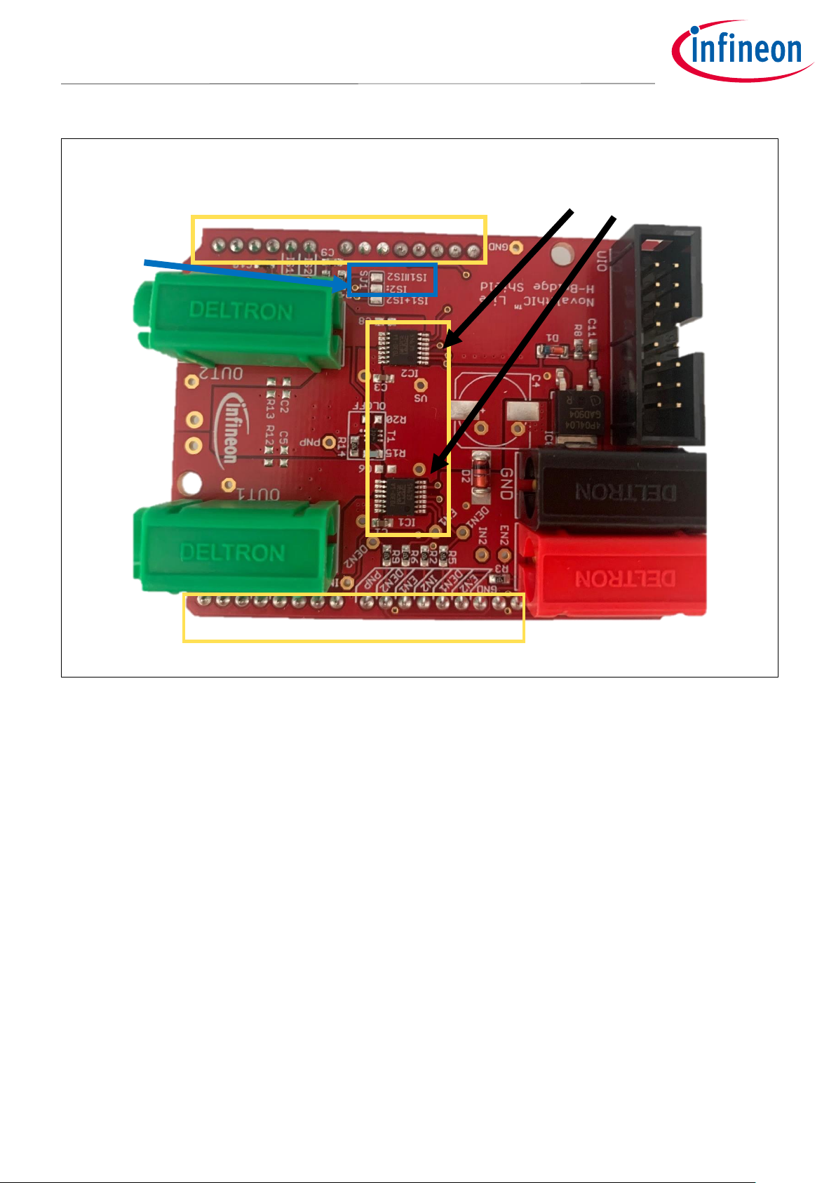
Figure 1 Motor Control Shield photo
As shown in Figure 1 in order to enable the usage of IC2 it is necessary to solder together the two pads marked
in blue frame.
ArduinoTM headers
TM
BTN7030-1EPA
OUT2
OUT1
GND
VS
IC2 enable
uIO Stick Port
Page 5
User Manual 5 Rev. 1.0
2021-01-21
Motor Control Shield for Arduino with BTN7030-1EPA
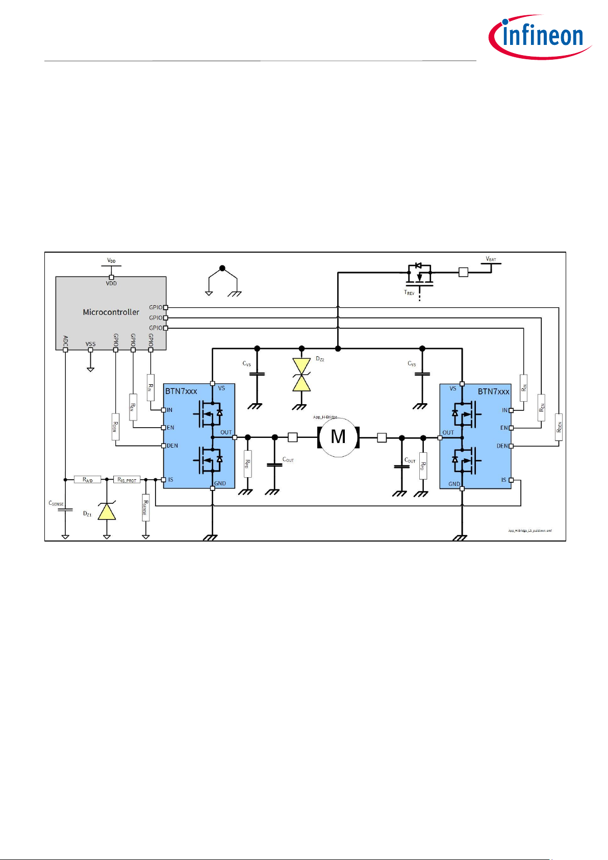
1.3 Block diagram of a full-bridge Motor Control
As a starting point for the Motor Control Shield, the application block diagram shown in Figure 2 was used. To
be flexible in the usage of the Motor Control Shield each IN, EN and DEN of the two half-bridges is connected to
a separate IO pin.
Figure 2 Application circuit for a bi-directional motor control with BTN7030-
Page 6

User Manual 6 Rev. 1.0
2021-01-21
Motor Control Shield for Arduino with BTN7030-1EPA
2 Motor Control Shield board description
For a safe and sufficient motor control design, discrete components are needed. Some of them must be
dedicated to the motor application and some to the NovalithIC™ Lite.
Figure 3, Figure 4 show the schematics plus the corresponding layout of the Motor Control Shield.
2.1 Schematics
In Figure 3 the schematics of the Motor Control Shield is shown. The schematics are based on the application
circuit in the BTN7030-1EPA Data Sheet.
Figure 3 Schematics Motor Control Shield for Arduino with BTN7030-1EPA
Page 7

User Manual 7 Rev. 1.0
2021-01-21
Motor Control Shield for Arduino with BTN7030-1EPA
Figure 4 Motor Control Shield for Arduino with BTN7030-1EPA – Layout
2.2 External components
All the external components shown in Figure 2 are described in the BTN7030-1EPA Design and PCB guideline
Application Note. Besides these components there are some others placed on this Arduino Shield in order to
insure the proper functioning.
C4, so called DC-link capacitor: This electrolytic capacitor is required to keep the voltage ripple at the VS-
pin low during switching operation. It is usually recommended that the voltage ripple at the Vs-pin to the GNDpin is kept below 1 V peak to peak. The value of C4 must be aligned accordingly. Most electrolytic capacitors are
less effective at cold temperatures. It must be assured that C4 is also effective under the worst case conditions
of the application. The layout is very important too. As shown in Figure 4, the capacitor C4 must be positioned
with very short wiring close to the NovalithIC™ Lite chip. This must be done to keep the parasitic inductors of
the PCB-wires as small as possible. On this shield capactior of 330 uF is mounted.
Page 8

User Manual 8 Rev. 1.0
2021-01-21
Motor Control Shield for Arduino with BTN7030-1EPA
C1/C3: This ceramic capacitors support C4 to keep the supply voltage ripple low and cover the fast
transients between the Vs-pin and the GND-pin. The layout wiring for C1/C3 must be shorter than for C4 to the
NovalithIC™ Lite to keep the parasitic PCB-wire inductance as small as possible. In addition the parasitic
inductance could be kept low by placing at least two vias for the connection to the GND-layer. On this shield
capactiors of 68 nF are mounted.
C6/C8: These ceramic capacitors are important for EMI. Good results have been achieved with a value of 220
nF. In terms of layout, it is important to place these capacitors between “OUT” and “Vs” without significant
additional wiring from C6/C8 to the Vs- and OUT-line. These capacitors are not mounted on this shield.
C5/C2: These ceramic capacitor help to improve the EMC immunity and the ESD performance of the
application. Good results have been achieved with a value of 220 nF. To keep the EMC and ESD out of the board,
the capacitor is most effective when positioned directly next to the board connector. In addition, the parasitic
inductance could be kept low by placing at least two vias for the connection to the GND-layer. These capacitors
are not mounted on this shield.
Page 9

User Manual 9 Rev. 1.0
2021-01-21
Motor Control Shield for Arduino with BTN7030-1EPA
3 BTN7030-1EPA overview
The BTN7030-1EPA used in the Motor Control Shield is an integrated high current half-bridge for motor drive
applications. Interfacing to a microcontroller is made easy by the integrated driver IC which features logic level
inputs, diagnosis with current sense, dead time generation, short circuit detection and protection against
overtemperature, undervoltage, overcurrent and cross current.
The BTN7030-1EPA provides a cost optimized solution targeting low power (<15 A) DC motor applications with
0 – 2 kHz.
3.1 Key features of the BTN7030-1EPA Novalith IC™
Path resistance of max. 62 mΩ @ 150°C (typ. 32 mΩ @ 25°C)
High side: max. 25.5 mΩ @ 150°C (typ. 12 mΩ @ 25°C)
Low side: max. 36.5 mΩ @ 150°C (typ. 20 mΩ @ 25°C)
Current limitation level of 14 A @ 150°C, 17 A @ 25°C
Status flag diagnosis with current sense capability
Overtemperature shut down with latch behavior
Undervoltage shut down
Cross current protection
Open load in ON and OFF detection
Short circuit to GND and VBAT detection
Driver circuit with logic level inputs
Operation up to 28 V (normal operation 6V – 18V)
Green Product (RoHS compliant)
AEC Qualified in PG-TSDSO-14 package
Page 10

User Manual 10 Rev. 1.0
2021-01-21
Motor Control Shield for Arduino with BTN7030-1EPA
3.2 Block diagram
The device is a monolithic chip integrated in SMART7 technology. BTN7030-1EPA is a protected half-bridge with
integrated driver, providing protection and diagnosis functions. The high side power stage is built using a Nchannel vertical power MOSFET with charge pump, while the low side power stage uses no charge pump. This
device has an exposed pad which ensures better cooling.
Figure 5 Block diagram BTN7030-1EPA
Page 11

User Manual 11 Rev. 1.0
2021-01-21
Motor Control Shield for Arduino with BTN7030-1EPA
3.3 Pin assignment
Figure 6 Pin assignment BTN7030-1EPA (top view)
3.4 Pin definitions and functions BTN7030-1EPA
Table 1
Pin
Symbol
I/O
Function
EP
VS - Supply Voltage
Battery voltage
2
EN I Enable
Digital signal to enable the normal operational mode (active
mode) of the BTN7030-1EPA and to clear the protection latch
3
DEN
I
Diagnosis enable
Digital signal to enable device diagnosis ("high" active) and to
clear the protection latch. If not used: connect to GND pin or to
module ground with a 10 kΩ resistor
4
IS I Sense current output
Analog/digital signal for diagnosis If not used: left open
6
IN I Input
Digital signal to switch ON either the low-side or high-side
output stage of the half-bridge
8-10
OUT
O
Output
Protected half-bridge power output
12-14
GND
-
Ground
Signal ground and ground connection for the low-side switch
1,5,7,11
n.c. - Not connected, internally not bonded
Page 12

User Manual 12 Rev. 1.0
2021-01-21
Motor Control Shield for Arduino with BTN7030-1EPA
4 Getting started
4.1 Target applications
The application targeted by the BTN7030-1EPA devices is brushed DC Motor Control (door lock, trunk lock,
cinching latch), but also solenoids and pumps. Besides Motor Control any other inductive, resistive and
capacitive load within the electrical characteristics of the NovalithIC
TM
Lite can be driven by this device.
With the Motor Control Arduino Shield either uni-directional DC-brushed motors or one bi-directional brushed
motor (with the two half-bridges used in full-bridge configuration) can be driven. The half-bridges are
controlled via the IN (Input) and EN (enable) pins. The BTN7030-1EPA also provides a sense current at the IS
pin, which is enabled by setting the DEN (diagnosis enable) pin.
4.1.1 Getting started: Arduino Shield
Choose a brushed DC motor.
Choose a DC adapter. The nominal input of the Power Shield is 6 – 18 V DC. Maximum Voltage is 2 V
Mount the Power Shield onto Arduino Uno R3 or XMC1100 Boot Kit.
Connect power supply (5 V) to the Arduino Uno R3 or XMC1100 Boot Kit (Micro USB).
Figure 7 Arduino Uno and XMC1100 boards
Program the controller board with the motor control software (Arduino – example Software).
o In order to use the Arduino code on XMC1100 Boot Kit it is necessary to install SEGGER J-Link.
For bi-directional applications connect the motor to OUT1 and OUT2 (full-bridge). For uni-directional
use, the motor can be placed between an output OUT1/OUT2 and either GND or VBAT (half-bridge).
Connect the Power supply to the Power Shield (VBAT, GND).
Turn on the power.
Page 13

User Manual 13 Rev. 1.0
2021-01-21
Motor Control Shield for Arduino with BTN7030-1EPA
4.1.2 Getting started: uIO Stick Software
Install Infineon Toolbox or lightweight Launcher
Connect the uIO Stick between the USB port of your PC and Infineon uIO Stick port (Figure 1) on the
Arduino shield.
Figure 8 uIO Stick
Under Manage Tools find Config Wizard for Single Half-Bridges and install it
When you open this Config Wizard you can configure the Shield according to your preferences and see
SENSE and OUT current waveforms, Figure 9.
Important to remember is that it is only possible to plot SENSE and OUT current of the IC1 on the board.
This limitation exists due to the configuration of the 16-pin uIO Stick port.
Page 14

User Manual 14 Rev. 1.0
2021-01-21
Motor Control Shield for Arduino with BTN7030-1EPA
Figure 9 Config Wizards (GUI) for uIO Stick
Page 15

User Manual 15 Rev. 1.0
2021-01-21
Motor Control Shield for Arduino with BTN7030-1EPA
5 Revision history
Document
version
Date of release
Description of change
1.0
2021-01-21
First release
Page 16

Trademarks of Infineon Technologies AG
All referenced product or service names and trademarks are the property of their respective owners.
Edition 2020-01-21
Published by
Infineon Technologies AG
81726 Munich, Germany
© 2021 Infineon Technologies AG.
All Rights Reserved.
Do you have a question about this
document?
Email: erratum@infineon.com
Document reference
IMPORTANT NOTICE
The information contained in this application note is
given as a hint for the implementation of the product
only and shall in no event be regarded as a
description or warranty of a certain functionality,
condition or quality of the product. Before
implementation of the product, the recipient of this
application note must verify any function and other
technical information given herein in the real
application. Infineon Technologies hereby disclaims
any and all warranties and liabilities of any kind
(including without limitation warranties of noninfringement of intellectual property rights of any
third party) with respect to any and all information
given in this application note.
The data contained in this document is exclusively
intended for technically trained staff. It is the
responsibility of customer’s technical departments
to evaluate the suitability of the product for the
intended application and the completeness of the
product information given in this document with
respect to such application.
For further information on the product, technology,
delivery terms and conditions and prices please
contact your nearest Infineon Technologies office
(www.infineon.com).
WARNINGS
Due to technical requirements products may contain
dangerous substances. For information on the types
in question please contact your nearest Infineon
Technologies office.
Except as otherwise explicitly approved by Infineon
Technologies in a written document signed by
authorized representatives of Infineon
Technologies, Infineon Technologies’ products may
not be used in any applications where a failure of the
product or any consequences of the use thereof can
reasonably be expected to result in personal injury.
 Loading...