

Page 1

μIO-Stick User Manual
About this document
Scope and purpose
The µIO-Stick is an interface device for controlling Infineon board/kits during run time through PC.
Intended audience
This document is intended for anyone using a µIO-Stick.
Z8F63272494
Application Note Please read the Important Notice and Warnings at the end of this document v1.1
www.infineon.com 2018-09-18
Page 2

Table of contents
About this document . . . . . . . . . . . . . . . . . . . . . . . . . . . . . . . . . . . . . . . . . . . . . . . . . . . . . . . . . . . . . . . . . . . 1
1 Acronyms . . . . . . . . . . . . . . . . . . . . . . . . . . . . . . . . . . . . . . . . . . . . . . . . . . . . . . . . . . . . . . . . . . . . . . . . . . . . . . 3
2 Overview . . . . . . . . . . . . . . . . . . . . . . . . . . . . . . . . . . . . . . . . . . . . . . . . . . . . . . . . . . . . . . . . . . . . . . . . . . . . . . .4
2.1 Description . . . . . . . . . . . . . . . . . . . . . . . . . . . . . . . . . . . . . . . . . . . . . . . . . . . . . . . . . . . . . . . . . . . . . . . . . . . . . 4
2.2 Key Features . . . . . . . . . . . . . . . . . . . . . . . . . . . . . . . . . . . . . . . . . . . . . . . . . . . . . . . . . . . . . . . . . . . . . . . . . . . . 6
2.3 Block Diagram . . . . . . . . . . . . . . . . . . . . . . . . . . . . . . . . . . . . . . . . . . . . . . . . . . . . . . . . . . . . . . . . . . . . . . . . . . 6
3 Hardware Connection . . . . . . . . . . . . . . . . . . . . . . . . . . . . . . . . . . . . . . . . . . . . . . . . . . . . . . . . . . . . . . . . . . .7
3.1 Pin Assignment . . . . . . . . . . . . . . . . . . . . . . . . . . . . . . . . . . . . . . . . . . . . . . . . . . . . . . . . . . . . . . . . . . . . . . . . . .7
3.2 Examples . . . . . . . . . . . . . . . . . . . . . . . . . . . . . . . . . . . . . . . . . . . . . . . . . . . . . . . . . . . . . . . . . . . . . . . . . . . . . . . 9
4 µIO-Stick Firmware Update . . . . . . . . . . . . . . . . . . . . . . . . . . . . . . . . . . . . . . . . . . . . . . . . . . . . . . . . . . . . 12
5 Fast LIN BSL Support . . . . . . . . . . . . . . . . . . . . . . . . . . . . . . . . . . . . . . . . . . . . . . . . . . . . . . . . . . . . . . . . . . 13
5.1 Installation Guideline . . . . . . . . . . . . . . . . . . . . . . . . . . . . . . . . . . . . . . . . . . . . . . . . . . . . . . . . . . . . . . . . . . . 13
5.2 BSL Tool . . . . . . . . . . . . . . . . . . . . . . . . . . . . . . . . . . . . . . . . . . . . . . . . . . . . . . . . . . . . . . . . . . . . . . . . . . . . . . . 13
5.2.1 Basic Mode . . . . . . . . . . . . . . . . . . . . . . . . . . . . . . . . . . . . . . . . . . . . . . . . . . . . . . . . . . . . . . . . . . . . . . . . . . .13
5.2.2 Expert Mode . . . . . . . . . . . . . . . . . . . . . . . . . . . . . . . . . . . . . . . . . . . . . . . . . . . . . . . . . . . . . . . . . . . . . . . . . .13
5.2.3 Configuration Dialog Box . . . . . . . . . . . . . . . . . . . . . . . . . . . . . . . . . . . . . . . . . . . . . . . . . . . . . . . . . . . . . . 15
5.2.4 Establish a Connection . . . . . . . . . . . . . . . . . . . . . . . . . . . . . . . . . . . . . . . . . . . . . . . . . . . . . . . . . . . . . . . . 17
5.2.5 Loading a HEX File . . . . . . . . . . . . . . . . . . . . . . . . . . . . . . . . . . . . . . . . . . . . . . . . . . . . . . . . . . . . . . . . . . . . 18
5.2.6 BSL Actions . . . . . . . . . . . . . . . . . . . . . . . . . . . . . . . . . . . . . . . . . . . . . . . . . . . . . . . . . . . . . . . . . . . . . . . . . . 19
5.2.6.1 Auto-Execute . . . . . . . . . . . . . . . . . . . . . . . . . . . . . . . . . . . . . . . . . . . . . . . . . . . . . . . . . . . . . . . . . . . . . . .19
5.2.6.2 Erase . . . . . . . . . . . . . . . . . . . . . . . . . . . . . . . . . . . . . . . . . . . . . . . . . . . . . . . . . . . . . . . . . . . . . . . . . . . . . .20
5.2.6.3 Download . . . . . . . . . . . . . . . . . . . . . . . . . . . . . . . . . . . . . . . . . . . . . . . . . . . . . . . . . . . . . . . . . . . . . . . . . 20
5.2.6.4 Verify . . . . . . . . . . . . . . . . . . . . . . . . . . . . . . . . . . . . . . . . . . . . . . . . . . . . . . . . . . . . . . . . . . . . . . . . . . . . . .21
5.2.6.5 Protection Enable/Disable . . . . . . . . . . . . . . . . . . . . . . . . . . . . . . . . . . . . . . . . . . . . . . . . . . . . . . . . . . .21
5.2.6.6 Run . . . . . . . . . . . . . . . . . . . . . . . . . . . . . . . . . . . . . . . . . . . . . . . . . . . . . . . . . . . . . . . . . . . . . . . . . . . . . . . 21
5.2.6.7 Read Out . . . . . . . . . . . . . . . . . . . . . . . . . . . . . . . . . . . . . . . . . . . . . . . . . . . . . . . . . . . . . . . . . . . . . . . . . . 21
5.3 Command Line Tool . . . . . . . . . . . . . . . . . . . . . . . . . . . . . . . . . . . . . . . . . . . . . . . . . . . . . . . . . . . . . . . . . . . . 22
6 Run-Time Control - Programming and Monitoring . . . . . . . . . . . . . . . . . . . . . . . . . . . . . . . . . . . . . . . 23
6.1 Installation Guideline . . . . . . . . . . . . . . . . . . . . . . . . . . . . . . . . . . . . . . . . . . . . . . . . . . . . . . . . . . . . . . . . . . . 23
6.2 Config Wizard . . . . . . . . . . . . . . . . . . . . . . . . . . . . . . . . . . . . . . . . . . . . . . . . . . . . . . . . . . . . . . . . . . . . . . . . . . 26
7 Updates and Purchases . . . . . . . . . . . . . . . . . . . . . . . . . . . . . . . . . . . . . . . . . . . . . . . . . . . . . . . . . . . . . . . . 28
Disclaimer . . . . . . . . . . . . . . . . . . . . . . . . . . . . . . . . . . . . . . . . . . . . . . . . . . . . . . . . . . . . . . . . . . . . . . . . . . . . 29
μIO-Stick User Manual
Table of contents
Application Note 2 v1.1
2018-09-18
Page 3

1 Acronyms
The following table summarizes the acronyms and their meanings throughout this document.
Table 1 Acronyms
Acronyms Names
USB Universal Serial BUs
BSL BootStrap Loader
CAN Controller Area Network
GND Ground
GPIO General Purpose Input Output
GUI Graphical User Interface
HID Human Interface Device
LIN Local Interconnect Network
MISO Master Input Slave Output
MOSI Master Output Slave Input
NAC No Activity Counter
NVM Non Volatile Memory
PWM Pulse Width Modulation
SBC System Basis Chip
SPI Serial Peripheral Interface
UART Universal Asynchronous Receiver Transmitter
VS Voltage Supply
μIO-Stick User Manual
1 Acronyms
Application Note 3 v1.1
2018-09-18
Page 4
2 Overview
2.1 Description
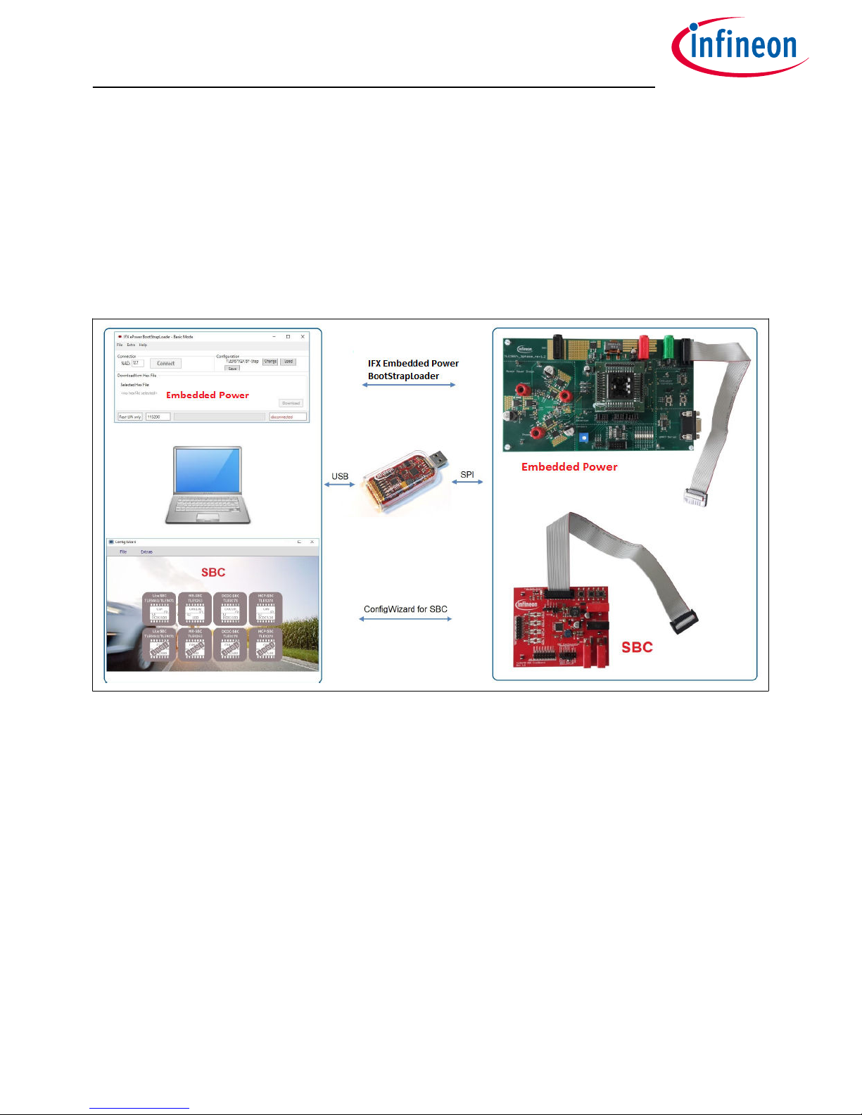
The µIO-Stick is an interface device for controlling Infineon boards/kits during run time through PC. It enables
the connection between the evaluation board and USB for SPI programming and monitoring. Besides, it plugs
into the evaluation board via a standard 16-pin connector and allows easy interface to the microcontroller via
USB for communication through UART, SPI, LIN. It also implements GPIO ports, PWM generation up to 20 kHz
and an analog measurement interface (ADC).
Figure 1 µIO-Stick Overview
The µIO-Stick provide two exclusive functions:
1. Infineon Embedded Power Fast LIN BSL Support
The Infineon Embedded Power devices provide a built-in boot strap loader (BSL), for programming the
embedded power devices over the built-in LIN transceiver or UART. The µIO-Stick acts as an interface
between the embedded power device and a PC. It handles the BSL protocols as well as the physical
layers. A PC application provides access to all BSL functions of the Embedded Power device.
Supported Embedded Power ICs:
• TLE984x family
• TLE986x family
• TLE987x family
2. Run-Time Control - Programming and Monitoring
The µIO-Stick connects the Evaluation Board with the computer. Via the ConfigWizard soware – a
powerful and intuitive Graphical User Interface (GUI) – the user gets a customized programming,
monitoring and evaluation support for various Infineon Automotive Products.
Supported Devices:
• System Basis Chip (SBC)
μIO-Stick User Manual
2 Overview
Application Note 4 v1.1
2018-09-18
Page 5

• High/low Side Switch (Spider+, SPOC)
• Half and Full Bridge Driver
μIO-Stick User Manual
2 Overview
Application Note 5 v1.1
2018-09-18
Page 6

2.2 Key Features
The µIO-Stick provides the following features:
• Communication with the connected device via LIN, SPI and UART
• Four GPIOs
• PWM signal generation up to 20 kHz
• Measurement of analog voltages up to 20 V
• Read and keep functionality to detect reset of the connected device
• USB HID device, no additional driver installation required
• µIO-Stick can power a target device
• Connected device can also be powered by external power supply for higher current
• 3 on-board status LEDs
• Additional BSL updater GUI for BSL communication with Embedded Power devices
2.3 Block Diagram
The µIO-Stick consists of an XMC4200 micro-controller which provides the necessary hardware interface and
handles the USB and BSL protocols.
LIN and RS232 are implemented as true physical layers (using LIN and MAX transceivers), while the digital lines
(SPI, GPIOs) provide a 5V-TTL level.
In addition, a small switchable charge-pump is implemented to generate a +12 V/200 mA supply for the target
device and the integrated LIN transceiver.
Figure 2 µIO-Stick Block Diagram
μIO-Stick User Manual
2 Overview
Application Note 6 v1.1
2018-09-18
Page 7
3 Hardware Connection
3.1 Pin Assignment
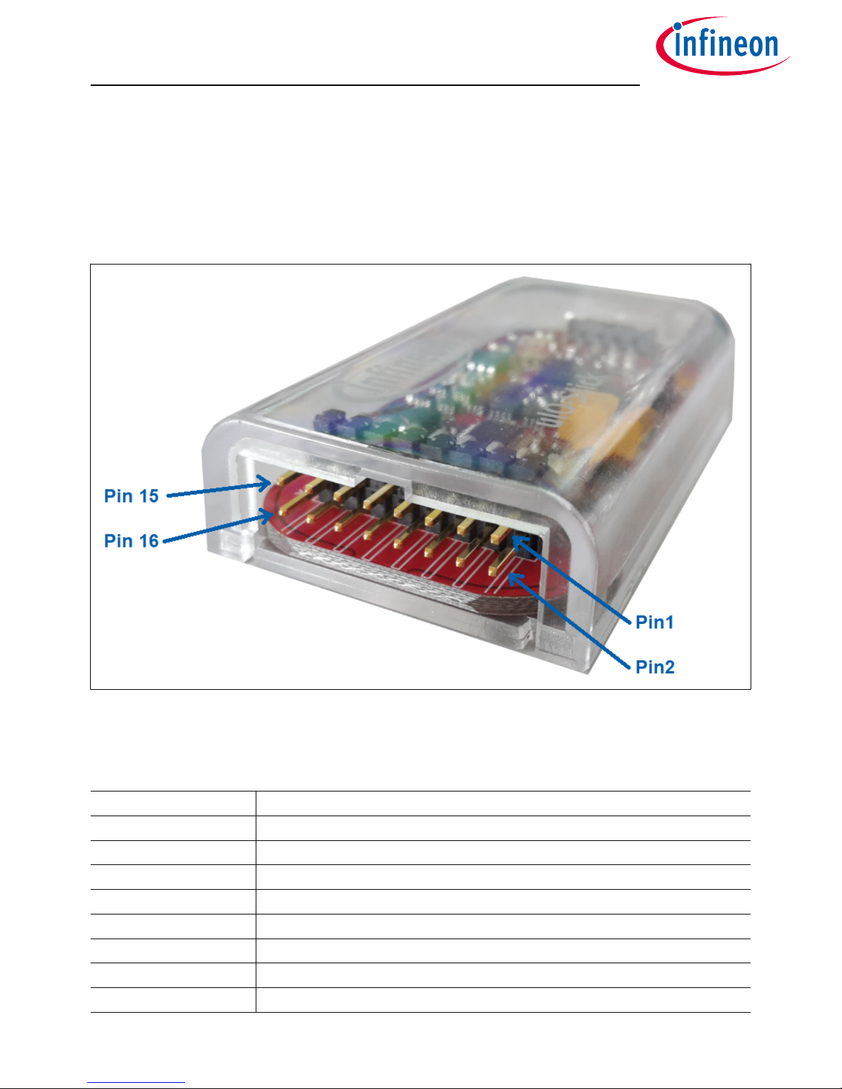
The µIO provides two interfaces, the USB interface to be plugged into the PC, and a 16-pin header to access the
BSL interface. Figure 3 provides a view into the 16-pin header of the µIO-Stick, including the pin numbering.
Figure 3 µIO-Stick Pin View
Table 2 lists the pin usage of the 16-pin header. The gray shaded pins are not used for BSL functions and
therefore will not be considered further.
Table 2 µIO-Stick Pin Assignment
PIN Description
1 RS232-TxD (out)
2 GND
3 RS232-RxD (in)
4 +5 V (USB, out)
5 LIN (physical, in/out)
6 VS (target supply, in/out)
7 Target Reset (5 V, out)
8 GPIO3 (5 V, in/out)
μIO-Stick User Manual
3 Hardware Connection
Application Note 7 v1.1
2018-09-18
Page 8

Table 2 µIO-Stick Pin Assignment (continued)
PIN Description
9 SPI/CS(5 V, out)
10 GPIO2 (5 V, in/out)
11 SPI CLK (5 V, out)
12 GPIO1 (5 V, in/out)
13 SPI MISO (5 V, in)
14 GPIO0 (5 V, in/out)
15 SPI MOSI (5 V, out)
16 analog in (max. 18 V)
Pins 1, 3 - RS232 They are used for UART BSL communication and need to be connected to the corresponding
RS232 inputs of the target board.
Attention: The RS232 pins are no TTL pins but real RS232 levels (MAX232 driven).
Pin 5 - LIN This is the LIN bus connection to the LIN transceiver implemented in the µIO- Stick, it is suited to
drive a corresponding LIN input of the target system.
Pin 7 - Target Reset This pin is intended to drive the reset input of the target device in order to synchronize the
device state with the attempts to establish a BSL connection. The connection of this pin to the reset of the target
device is not necessarily required, as synchronization can also be achieved by:
• power cycling of the target device by Pin 6 (VS)
• keeping the target device in BSL mode by configuring an appropriate NAC value
Pin 2 - GND This is the common ground connection to the target system.
Pin 6 - VS This pin can either be driven from the implemented charge-pump of the µIO-Stick (+12 V/200 mA) or
can be overridden by an external supply, i.e. the supply of the target device. This pin is also being used to
internally drive the LIN transceiver available on the µIO-Stick. If BSL communication over the LIN interface is
intended, then the supply of Pin 6 is mandatory.
μIO-Stick User Manual
3 Hardware Connection
Application Note 8 v1.1
2018-09-18
Page 9

3.2 Examples
Figure 4 shows the minimum required connection from the µIO-Stick to the target device in order to establish a
BSL communication over the LIN interface. This applies to both Normal-LIN and FastLIN protocols. To be able to
establish a BSL connection, the target device either has to stay in BSL mode upon power up (fresh device), or a
power cycling (VS - Pin 6) done by the µIO-Stick would be required.
Figure 4 Normal LIN and FastLIN connection, without reset, target supplied by µIO
Figure 5 shows a connection scenario with reset. The µIO-Stick actively resets the target device in order to start
BSL communication. In this case a power cycling of the VS (Pin 6) by the µIO-Stick would not be required.
Figure 5 Normal LIN and FastLIN connection, with reset, target supplied by µIO
μIO-Stick User Manual
3 Hardware Connection
Application Note 9 v1.1
2018-09-18
Page 10

Figure 6 shows a connection example where the target device and also the µIO-Stick is supplied by an separate
power supply. Since in this case the µIO-Stick would not be able to perform a VS power cycling to restart the
device it is wise to connect the reset line as well. If the target device stays in BSL mode upon power-up, such as
for a new, unprogrammed device then the reset line is not required.
Figure 6 Normal LIN and FastLIN connection, with reset, target supplied by separate power
supply
μIO-Stick User Manual
3 Hardware Connection
Application Note 10 v1.1
2018-09-18
Page 11

Figure 7 shows another example of how to connect the µIO-Stick to the target device, by simply plugging the
ribbon cable to the BSL-connector of the evaluation board. Hereby all interfaces (LIN and UART) are supported.
Figure 7 Direct connection of µIO-Stick to evaluation board, LIN-, FastLIN- and UART-BSL
μIO-Stick User Manual
3 Hardware Connection
Application Note 11 v1.1
2018-09-18
Page 12

4 µIO-Stick Firmware Update
The µIO Stick comes with the capability to update the firmware of the integrated XMC4200 micro-controller
either to provide new features to the customer, or to be able to correct issues with the firmware.
To update the firmware, the file uIO-Updater.exe and a HEX file is required. uIO-Updater.exe is a command line
tool, where the hex file to be loaded has to be given as command line input. For example:
C:\>uIO-Updater.exe -FW="bsl_1.1.346.fw"
The example above flashes the "BSL_V1.1.346.hex" file into the µIO-Stick. Aer the firmware update has
finished, please unplug the µIO-Stick from USB and reconnect it.
μIO-Stick User Manual
4 µIO-Stick Firmware Update
Application Note 12 v1.1
2018-09-18
Page 13

5 Fast LIN BSL Support
There are two soware components required to use the BSL feature of the target device. Part 1 is the firmware
of the XMC4200 microcontroller mounted on the µIO-Stick. This firmware is responsible to generate the BSL
communication protocol. Part 2 is the BSL user soware running on a Microso® Windows® PC. It provides the
user interface and prepares the data packets to be sent to the µIO-Stick and further to the target device.
5.1 Installation Guideline
1. Go to the section Tools & Soware of the µIO-Stick
2. Download uIO_BSL_Tool.zip and extract all the files
3. Connect the µIO-Stick via USB to the PC and via the 16-pin connector to the target device
4. Update the µIO-Stick with the current BSL firmware version by executing the script UpdateBSL
5. Launch the application BSL_Tool.exe
5.2 BSL Tool
The BSL GUI tool is the user interface to control the BSL interactively. It provides two modes of operation, a
Basic Mode and an Expert Mode.
5.2.1 Basic Mode
The Basic Mode provides a reduced user interface limited to the minimum required actions, such as download
of code into the target device.
Figure 8 shows the user interface of the Basic Mode.
Figure 8 BSL Tool - Basic Mode
5.2.2 Expert Mode
The Expert Mode provides much more functionality, all functions of the BSL modes supported by the target
device are available in this mode. In order to switch to Expert Mode from Basic Mode, select the Expert Mode in
the Extra menu, as shown in Figure 9 on page 14 .
μIO-Stick User Manual
5 Fast LIN BSL Support
Application Note 13 v1.1
2018-09-18
Page 14

Figure 9 BSL Tool - Select Expert Mode
Figure 10 on page 15 displays the user interface of the Expert Mode. The Expert Mode enables all possible BSL
actions, including target device erase, code download, device protection, code execution, and code upload. The
arrangement of these functions in the GUI is kept in the natural order of execution of these actions, i.e. erase
function at the top, followed by download, verify, etc..
μIO-Stick User Manual
5 Fast LIN BSL Support
Application Note 14 v1.1
2018-09-18
Page 15

Figure 10 BSL Tool - Expert Mode
5.2.3 Configuration Dialog Box
Before a BSL connection is established, the target device and the BSL interface and protocol have to be
selected. The Configuration block lists the currently selected target device, while the status bar at the bottom of
the window displays the selected BSL interface/protocol and baud rate. In order to change these settings, press
the Change button inside the Configuration block. Please also refer to Figure 11 on page 16.
μIO-Stick User Manual
5 Fast LIN BSL Support
Application Note 15 v1.1
2018-09-18
Page 16

Figure 11 BSL Tool - Configuration Button
Figure 12 displays the Configuration dialog. Here, the user selects the desired target device, BSL protocol, baud
rate, and the behavior of the integrated VS charge pump.
Figure 12 BSL Tool - Configuration
• Target Device - select the target device from the pull-down list.
• Protocol - select the desired BSL protocol and BSL interface:
- Normal LIN - BSL communication uses real LIN frames, Master-Request frames, and Slave-Response
frames. In order to distinguish these BSL LIN frames from real LIN frames, the checksum is inverted.
Communication is via the target device integrated LIN transceiver.
- Fast-LIN - UART like BSL communication using the device integrated LIN transceiver. This is the default
protocol for new, unprogrammed devices.
- UART - full-duplex UART communication over UART1 of the target device.
• Baud Rate - selects the communication baud rate.
• Pin VS - selects the usage/behavior of the VS pin (Pin 6):
- O - the µIO-Stick integrated charge pump is switched o, VS must be supplied by the target system,
see also Figure 6 on page 10.
- On - the µIO-Stick integrated charge pump is switched on, and remains on. Please see also Figure 5 on
page 9.
- O during Reset - the µIO-Stick integrated charge pump is switched o during the reset phase before
the connection attempt is started, see also Figure 4 on page 9.
μIO-Stick User Manual
5 Fast LIN BSL Support
Application Note 16 v1.1
2018-09-18
Page 17

5.2.4 Establish a Connection
Once the configuration has been completed, the connection to the target device can be established. If the µIOStick is not connected to the PC system, the Connect button is shaded gray, as shown Figure 13.
Figure 13 BSL Tool - No µIO-Stick found
Once the µIO-Stick is recognized, by the BSL tool the connect button turns orange. By pressing the Connect
button, the BSL tool tries to establish a connection using the selected BSL interface and BSL protocol.
Figure 14 BSL Tool - Ready to connect to target system
Figure 15 on page 18 displays the connected state, the logging window states that the BSL communication has
been established, and the status bar at the bottom of the window shows “connected”.
μIO-Stick User Manual
5 Fast LIN BSL Support
Application Note 17 v1.1
2018-09-18
Page 18

Figure 15 BSL Tool - Connected
5.2.5 Loading a HEX File
The main use of the BSL tool will be the downloading of a HEX file, containing the user application code. Via the
File menu, a HEX file can be chosen and loaded, see Figure 16 on page 19.
μIO-Stick User Manual
5 Fast LIN BSL Support
Application Note 18 v1.1
2018-09-18
Page 19

Figure 16 BSL Tool - Loading a HEX file
5.2.6 BSL Actions
Once the desired Hex file has been selected, the supported BSL actions can now be executed. The order of the
actions placed on the GUI follows a natural flow: Erase -> Download/Verify -> Protection -> Run.
5.2.6.1 Auto-Execute
Each of these action groups provides an “auto execute” check box. If it is checked, the corresponding action is
added to the “Auto Execute” list. Figure 17 on page 20 shows an example of the “Auto Execute” list, where
everything except Protection is added to the list. By pressing the “Auto Exec” button, the actions added to the
list are executed with a single click.
μIO-Stick User Manual
5 Fast LIN BSL Support
Application Note 19 v1.1
2018-09-18
Page 20

Figure 17 BSL Tool - Auto Execute
5.2.6.2 Erase
The action Erase erases the built-in NVM module of the target device. The user can select between various
sections of the NVM to be erased, which are:
• Full Chip - the entire user accessible NVM will be erased.
• Range from ... to ... - only the user defined range will be erased.
• Used Sections - only those NVM regions occupied by the selected HEX file will be erased.
5.2.6.3 Download
The action Download transfers a loaded HEX file into the target device.
μIO-Stick User Manual
5 Fast LIN BSL Support
Application Note 20 v1.1
2018-09-18
Page 21

5.2.6.4 Verify
The action Verify is used to check the integrity of the code inside the target device NVM against the selected
HEX file.
5.2.6.5 Protection Enable/Disable
The action Protection either sets the protection of the target device, or resets it. In both cases, a password
dialog opens up, the user has to enter an 8-bit password. See Figure 18.
Figure 18 BSL Tool - Password Dialog
If the Protection is set, the target device does no longer accept any NVM change operations, nor allow code
readout. In addition, the SWD interface (ARM) or the DAP interface (8051) is disabled.
To reset the Protection status, the same matching 8-bit password used to set the protection has to be provided
in the Password Dialog. If the password matches, the entire NVM of the target device is erased and the target
device is fully accessible again.
If the “Auto Execute” feature is being used for the Protection Action, then the Password dialog opens to be able
to define the password used for the “Auto Execution” flow.
5.2.6.6 Run
The action Run starts the execution of the code inside the target device. The BSL connection is terminated by
this action.
5.2.6.7 Read Out
The action Read Out is only available for the protocols “Fast-LIN” or “UART”, it is not available for “Normal LIN”.
It reads and transfers the target device NVM content to the PC system. The user has to define the address range
to be read.
μIO-Stick User Manual
5 Fast LIN BSL Support
Application Note 21 v1.1
2018-09-18
Page 22

5.3 Command Line Tool
In order to run the BSL actions none-interactively, a command line BSL tool is provided. It is named
BSL_Cmd.exe, and should be run from a terminal window. Executing BSL_Cmd.exe without any parameters
generates a list of the supported options, as shown below:
C:\>BSL_Cmd.exe
----------------------------------------------------Bootstrap Loader Command Line Tool v1.2 build 638
----------------------------------------------------ERROR : missing arguments
Valid commands are:
-Cmode=baud,NAD connection mode and baud rate
-EF erase full chip
-ER=start-end erase range
-D="hex_file" download hex file (repeatable)
-VS=n function of VS pin. 0: off, 1:on, 2:off during reset
-V=1 verify after download
-PS=password set protection
-PR=password reset protection
-R100TP=page,"hex_file" read the selected 100TP page and save it
-RO="hex_file",start-end read out range into hex
-R=NVM run in NVM
-R=RAM run in RAM
-T=device target device
-NACNAD=nac,nad,bslMode set NAC, NAD and BSL mode (F:fastLIN, L:LIN)
-W100TP=page,"hex_file" write hex file to selected 100TP page
-Q quite mode
mode : N/F/FO/U N=Normal LIN, F=Fast-LIN, FO=Fast-LIN-only, U=UART
baud : baud rate 9600..115200
hex_file : defines the hex file for the download
page : selects 100TP page (1..8)
start : defines the start address for the operation
end : defines the end address for the operation
device : defines the target device (s. TargetConfiguration.xml)
-------------------------------------------------------------------------------
The code above shows a call of BSL_Cmd.exe with various options, which are:
• -CFO=115200,1 : Fast-LIN-only, 115200 baud, NAD = 1
• -T=TLE9879QX : target device TLE9879QX, it has to match the device select list in the Configuration Dialog
• -VS=1 : VS (Pin 6) on all the time
• -EF : Erase full chip
• -D=”Blinky.hex” : downloads the Blinky.hex file to the target device
• -PS=0x55 : sets protection with the 8-bit password 0x55
μIO-Stick User Manual
5 Fast LIN BSL Support
Application Note 22 v1.1
2018-09-18
Page 23

6 Run-Time Control - Programming and Monitoring
6.1 Installation Guideline
1. Download and install the Infineon Toolbox
2. Select the tab "Manage tools", search for SBC, and click "Install"
Figure 19 Installation of Config Wizard for SBC
3. Select the tab "My tools". If the installation was successful, you should see the icon for "Config Wizard for
SBC"
Figure 20 Config Wizard for SBC installed successfully
4. Click on "Start" and select the required chip.
μIO-Stick User Manual
6 Run-Time Control - Programming and Monitoring
Application Note 23 v1.1
2018-09-18
Page 24

Figure 21 Chips for SBC in Config Wizard
For example, here with the TLE9278-3QX Evalboard correctly supplied, the following screen should
display:
Figure 22 Config Wizard with SBC TLE9278
μIO-Stick User Manual
6 Run-Time Control - Programming and Monitoring
Application Note 24 v1.1
2018-09-18
Page 25

Warning: Please ensure that the latest firmware is flashed onto the µIO-Stick. Otherwise, select the tab
"Extra", then click "Update uIO...".
Figure 23 Select Extra > Update uIO...
Select the file "uIO_V221.hex" and click "OK".
Figure 24 Select HEX file with the right version for µIO-Stick
When the update is completed, the µIO Firmware version should be 2.2.1.
μIO-Stick User Manual
6 Run-Time Control - Programming and Monitoring
Application Note 25 v1.1
2018-09-18
Page 26

6.2 Config Wizard
The Config Wizard is a Graphical User Interface which provides an easy access to SBC features and the SPI
registers.
Figure 25 Config Wizard Graphical User Interface
μIO-Stick User Manual
6 Run-Time Control - Programming and Monitoring
Application Note 26 v1.1
2018-09-18
Page 27

Figure 26 Config Wizard Control Functions
μIO-Stick User Manual
6 Run-Time Control - Programming and Monitoring
Application Note 27 v1.1
2018-09-18
Page 28

7 Updates and Purchases
For updates of the BSL tool soware or the µIO-Stick firmware as well as for purchasing the µIO-Stick, please
visit www.hitex.com/uio.
μIO-Stick User Manual
7 Updates and Purchases
Application Note 28 v1.1
2018-09-18
Page 29

Trademarks
All referenced product or service names and trademarks are the property of their respective owners.
Edition 2018-09-18
Published by
Infineon Technologies AG
81726 Munich, Germany
©
2018 Infineon Technologies AG
All Rights Reserved.
Do you have a question about any
aspect of this document?
Email: erratum@infineon.com
Document reference
IFX-wxj1535378137899
IMPORTANT NOTICE
The information contained in this application note is
given as a hint for the implementation of the product
only and shall in no event be regarded as a description
or warranty of a certain functionality, condition or
quality of the product. Before implementation of the
product, the recipient of this application note must
verify any function and other technical information
given herein in the real application. Infineon
Technologies hereby disclaims any and all warranties
and liabilities of any kind (including without limitation
warranties of non-infringement of intellectual property
rights of any third party) with respect to any and all
information given in this application note.
The data contained in this document is exclusively
intended for technically trained sta. It is the
responsibility of customer’s technical departments to
evaluate the suitability of the product for the intended
application and the completeness of the product
information given in this document with respect to such
application.
WARNINGS
Due to technical requirements products may contain
dangerous substances. For information on the types
in question please contact your nearest Infineon
Technologies oice.
Except as otherwise explicitly approved by Infineon
Technologies in a written document signed by
authorized representatives of Infineon Technologies,
Infineon Technologies’ products may not be used in
any applications where a failure of the product or
any consequences of the use thereof can reasonably
be expected to result in personal injury
 Loading...