

Page 1

AN2018
-35 EVAL-M1-IM818-A User Manual
EVAL-M1-IM818-A User Manual
iMOTION™ Modular Application Design Kit
About this document
Scope and purpose
This application note provides an overview of the evaluation board EVAL-M1-IM818-A including its main
features, key data, pin assignments and mechanical dimensions.
EVAL-M1-IM818-A is a complete evaluation board including a 3-phase CIPOS™ Maxi Intelligent Power Module
(IPM) for motor drive application. In combination with control-boards equipped with the M1 20pin interface
connector, like EVAL-M1-101T or EVAL-M1-099M, it features and demonstrates Infineon’s CIPOS™ Maxi IPM
technology for motor drive.
The evaluation board EVAL-M1-IM818-A was developed to support customers during their first steps
designing applications with CIPOS™ Maxi IPM.
CIPOS™ Maxi IPM in this board is IM818-MCC which has three phase inverter with 1200V TRENCHSTOP™
IGBTs and Emitter Controlled diodes are combined with an optimized 6-channel SOI gate driver. It is
Optimized to industrial applications like Ventilation and Air Conditioning.
Intended audience
This application note is intended for all technical specialists working with the EVAL-M1-IM818-A board.
Table of Contents
About this document ....................................................................................................................... 1
Table of Contents ........................................................................................................................... 1
1 Safety precautions ......................................................................................................... 3
2 Introduction .................................................................................................................. 4
3 Main features ................................................................................................................ 5
3.1 EVAL-M1-IM818-A board specifications .................................................................................................. 6
3.2 Pin assignments ...................................................................................................................................... 8
4 Getting Started with EVAL-M1-IM818-A ........................................................................... 10
4.1 Setting up the system............................................................................................................................ 10
4.2 iMOTION™ development tools and software ....................................................................................... 12
4.2.1 MCEWizard setup overview .............................................................................................................. 12
4.2.2 MCEDesigner setup overview .......................................................................................................... 14
5 Hardware description of EVAL-M1-IM818-A ...................................................................... 16
5.1 DC bus Measurement and MCEWizard configuration .......................................................................... 16
5.1.1 Motor External Current feedback configuration and calculation .................................................. 17
5.2 EMI filter and soft power up circuit ....................................................................................................... 20
5.3 Inverter section using CIPOS™ Maxi IPM............................................................................................... 21
5.4 Auxiliary power supply .......................................................................................................................... 22
5.5 Schematic with EVAL-M1-IM818-A evaluation board ........................................................................... 23
5.6 PCB Layout ............................................................................................................................................ 24
6 Bill of Materials of EVAL-M1-IM818-A ............................................................................... 28
User Manual Please read the Important Notice and Warnings at the end of this document <Revision 1.1>
www.infineon.com <2019-04-02>
Page 2

Safety precautions
EVAL-M1-IM818-A User Manual
iMOTION™ Modular Application Design Kit
7 Reference .................................................................................................................... 31
User Manual 2 <Revision 1.1>
<2019-04-02>
Page 3

EVAL-M1-IM818-A User Manual
iMOTION™ Modular Application Design Kit
Safety precautions
1
In addition to the precautions listed throughout this manual, please read and understand the following
statements regarding hazards associated with development systems.
Table 1
Safety precautions
Precautions
Caution: The ground potential of the EVAL-M1-IM818-A board is biased to a negative
DC bus voltage potential. When measuring voltage waveform by oscilloscope, the
scope’s ground needs to be isolated. Failure to do so may result in personal injury or
death, and equipment damage. Darkened display LEDs are not an indication that
capacitors have discharged to safe voltage levels.
Caution: EVAL-M1-IM818-A system contains DC bus capacitors which take time to
discharge after removal of the main supply. Before working on the drive system,
wait three minutes for capacitors to discharge to safe voltage levels. Failure to do so
may result in personal injury or death. Darkened display LEDs are not an indication
that capacitors have discharged to safe voltage levels.
Caution: Only personnel familiar with the drive and associated machinery should
plan or implement the installation, start-up and subsequent maintenance of the
system. Failure to comply may result in personal injury and/or equipment damage.
Caution: The surfaces of the drive may become hot, which may cause injury.
Caution: The EVAL-M1-IM818-A board contains parts and assemblies sensitive to
electrostatic discharge (ESD). Electrostatic control precautions are required when
installing, testing, servicing or repairing this assembly. Component damage may
result if ESD control procedures are not followed. If you are not familiar with
electrostatic control procedures, refer to applicable ESD protection handbooks and
guidelines.
Caution: An incorrectly applied or installed drive can result in component damage
or reduction in product lifetime. Wiring or application errors such as undersized
motor, incorrect or inadequate DC supply, or excessive ambient temperatures may
result in system malfunction.
Caution: Remove or connect the control board from or to the power drive. Wait three
minutes after removing power from the power drive to discharge the bus capacitors.
Do not attempt to service the drive until the bus capacitors have discharged to zero.
Failure to do so may result in personal injury or death.
Caution: The EVAL-M1-IM818-A board is shipped with packing materials that need to
be removed prior to installation. Failure to remove all packing materials which are
unnecessary for system installation may result in overheating or abnormal
operating condition.
User Manual 3 <Revision 1.1>
<2019-04-02>
Page 4

Introduction
EVAL-M1-IM818-A User Manual
iMOTION™ Modular Application Design Kit
2 Introduction
The EVAL-M1-IM818-A evaluation board is a part of the iMOTION™ Modular Application Design Kit for drives
(iMOTION™ MADK).
The MADK platform is intended to use various power stages with different control boards. These boards can
easily be interfaced through the iMOTION™ MADK M1 interface connector which is 20 pin connector.
This evaluation board is designed to give easy-to-use power stage based on the Infineon's CIPOS™ Maxi
Inteligent Power Module (IPM). The board is equipped with all assembly circuit for sensorless field oriented
control (FOC). It provides a single-phase AC-connector, rectifier and 3-phase output for connecting the
motor. The power stage also contains emitter (leg) shunts for current sensing and a voltage divider for DClink voltage measurement.
The EVAL-M1-IM818-A evaluation board is available through regular Infineon distribution partners as well as
on Infineon's website. The features of this board are described in the design feature chapter of this
document, whereas the remaining paragraphs provide information to enable the customers to copy, modify
and qualify the design for production according to their own specific requirements.
Environmental conditions were considered in the design of the EVAL-M1-IM818-A. The design was tested as
described in this document but not qualified regarding safety requirements or manufacturing and operation
over the whole operating temperature range or lifetime. The boards provided by Infineon are subject to
functional testing only.
Evaluation boards are not subject to the same procedures as regular products regarding Returned Material
Analysis (RMA), Process Change Notification (PCN) and Product Discontinuation (PD). Evaluation boards are
intended to be used under laboratory conditions and by trained specialists only.
The block diagram of the EVAL-M1-IM818-A is depicted in Figure 1. This evaluation board includes a DC EMI
filter and soft power up circuit, 20-pin iMOTION™ MADK-M1 interface connector, auxiliary power supply to
provide 15 V and 3.3 V, and the CIPOS™ Maxi IPM IM818-MCC.
CIPOSTM Maxi IPM
Power
A
B
C
EMI Filter
& Soft
Power Up
Circuit
Supply
PWM
15V & 3.3V
DCBsense
20 pin iMOTION
MADK-M1 connector
GK
15V
PWM
I
& protection
trip
circuit
VTH
TM
Itrip
RFE
VTH
HVIC
M
Figure 1 The Block Diagram of the EVAL-M1-IM818-A
CIPOS™ Maxi IPM in this board is IM818-MCC which has 1200 V of voltage and 10A of current rating. It is Optimized
6-channel SOI gate driver for excellent electrical performance. It is designed to control 3 phase AC motors and
permanent magnet motors in variable speed drives applications such as low power motor drives.
User Manual 4 <Revision 1.1>
<2019-04-02>
Page 5

Main features
EVAL-M1-IM818-A User Manual
iMOTION™ Modular Application Design Kit
3 Main features
EVAL-M1-IM818-A is an evaluation board for motor drive applications based on a 3-phase IPM. Combined
with one of the available MADK control board options, it demonstrates Infineon's IPM technology for motor
drives. The kit demonstrates Infineon’s IPM technology for motor drives.
Main features of CIPOS™ Maxi IPM IM818-MCC are:
• 1200 V TRENCHSTOP™ IGBT4
• Maximum blocking voltage V
• Maximum output current at 25 °C case temperature IC = 16 A
• Rugged 1200 V SOI gate driver technology with stability against transient and negative voltage
• Allowable negative VS potential up to -11 V for signal transmission at VBS = 15 V
• Integrated bootstrap functionality
• Overcurrent shutdown
• Built-in NTC thermistor for temperature monitoring
• Under-voltage lockout at all channels
• Low side emitter pins accessible
• For all phase current monitoring (open emitter)
• Cross-conduction prevention
• All of 6 switches turn off during protection
• Programmable fault clear timing and enable input
• Lead-free terminal plating; RoHS compliant
= 1200 V
CES
The evaluation board characteristics are:
• Nominal input voltage 380 VAC
• Default 1.5 kW motor power output
• On board EMI filter
• Current sensing for each leg configured by default
• Sensing of DC-link voltage
• Measurement test-points compatible to standard oscilloscope probes
• PCB size is 197 mm x 140 mm and has two layers with 35 µm copper each
• RoHS compliant
User Manual 5 <Revision 1.1>
<2019-04-02>
Page 6

Main features
Values
Conditions
Voltage
Input current
Power (3
phases)
Phase
Current
Maximum DC bus voltage
820 V Lim
ited by
electrolytic capacitor
which
Minimum
DC bus voltage
A
ux power supply can start
Current sensing resistors RS
U
,
25mΩ X 3 Two 50mΩ in parallel for one leg
Output current trip level
20
A
Current feedback to controller, so over
Temperature trip level
100 °C Internal NTC temperature to controller.
15 V 15 V ± 5 %,
max. 250 mA Used for
CIPOS
™ IPM
gate driver
and LDO
3.3 V
3.3 V
± 2
%, max. 200mA Su
pplying the 3.3V to the controller board
Material
FR4, 1.6 mm
thickness, 2
layers.
Dimension
197
mm x
140 mm x 70mm
Ambient temperature
From 0 to
43°C
Non-condensing, maximum RH of 95 %
EVAL-M1-IM818-A User Manual
iMOTION™ Modular Application Design Kit
3.1 EVAL-M1-IM818-A board specifications
Table 2 depicts the important specifications of the evaluation board EVAL-M1-IM818-A.
Table 2 EVAL-M1-IM818-A board specifications
Parameters
Input
Output
DC Bus Voltage
Current feedback
RSV, RSW
Protections
380 V
rms
6 A
rms
1500 W
2.35A
rms
400 V
peak
±20% VAC input
Input 380 VAC, Ta=25C
Input 380VAC, f
TC=100°C, Natural convection
Input 380VAC , f
TC=100°C, Natural convection
max voltage is 900V
current protection level is decided by
controller. This Itrip level for IPM
/ comments
=6 kHz, Ta=25°C,
PWM
=6 kHz, Ta=25°C,
PWM
On board power supply
PCB characteristics
System environment
Recommend to set this level for protection
35 µm copper thickness
User Manual 6 <Revision 1.1>
<2019-04-02>
Page 7

1. J1 -
AC Line connector
EVAL-M1-IM818-A User Manual
iMOTION™ Modular Application Design Kit
Main features
Figure 2 points out the functional groups on the top side of the EVAL-M1-IM818-A evaluation board.
2. Relay and Fuse
3. J2 - 20 pin iMOTION™ MADK-M1 interface
connector for controller board
4. Shunt resistors
5. EMI filter
6. Auxiliary power supply
7. J3 - Motor phase connector
8. CIPOS™ Maxi IPM
9. Rectifier bridge DB
Figure 2 Functional groups of the EVAL-M1-IM818-A evaluation board’s top side
User Manual 7 <Revision 1.1>
<2019-04-02>
Page 8

Main features
EVAL-M1-IM818-A User Manual
iMOTION™ Modular Application Design Kit
3.2 Pin assignments
General information about the connectors of the EVAL-M1-IM818-A evaluation board is reported. Table 3
includes the details of the AC line connector J1.
Table 3 J1- AC Line connector
S. No. Pin Details
1 EARTH Earth ground
2 Not used Not used
3 A AC line input (380V)
4 B AC line input (380V)
5 C AC line input (380V)
Table 4 provides the pin assignments of the 20 pin iMOTION™ MADK-M1 interface connector J2. This
connector is the interface to the controller board.
Table 4 J2 - iMOTION™ MADK-M1 20 pin interface connector for controller board
Pin Name Pin Name Connectors
1 PWMUH 3.3 V compatible logic input for high side gate driver-Phase U
2 GND Ground
3 PWMUL 3.3 V compatible logic input for low side gate driver-Phase U
4 GND 4 GND Ground
5 PWMVH 3.3 V compatible logic input for high side gate driver-Phase V
6 +3.3V On board 3.3 V supply
7 PWMVL 3.3 V compatible logic input for low side gate driver-Phase V
8 +3.3V On board 3.3 V supply
9 PWMWH 3.3 V compatible logic input for high side gate driver-Phase W
10 I_U Shunt voltage phase U
11 PWMWL 3.3 V compatible logic input for low side gate driver-Phase W
12 I_U- Ground
13 GK Gate kill signal – active low when overcurrent is detected
14 DCBSENSE DC bus positive voltage, scaled in 0-3.3 V range by a voltage divider
15 VTH Thermistor Output
16 I_V Shunt voltage phase V
17 I_V- Ground
18 I_W Shunt voltage phase W
19 I_W- Ground
20 VCC 15 V Power Supply
User Manual 8 <Revision 1.1>
<2019-04-02>
Page 9

Main features
EVAL-M1-IM818-A User Manual
iMOTION™ Modular Application Design Kit
Table 5 denotes the details of the motor side connector J2.
Table 5 J2- Motor side connector
S. No. Pin Details
1 W Connected to motor phase U
2 V Connected to motor phase V
3 U Connected to motor phase W
User Manual 9 <Revision 1.1>
<2019-04-02>
Page 10
Getting Started with EVAL
-M1-
IM818
-A
PC-USB
C
onnector
AC Power
I
nput
Motor
P
hase
O
utput
s
EVAL-M1-IM818-A User Manual
iMOTION™ Modular Application Design Kit
4 Getting Started with EVAL-M1-IM818-A
In order to run the motor system, a combination of the iMOTION™ MADK power board (EVAL-M1-IM818-A)
and the matching MADK control board is required. The iMOTION™ Software Tools MCEDesigner and
MCEWizard are also required in order to initialy setup the system, as well as to control and fine-tune the
system performance to match users exact needs. This chapter provides more details on setting up the
system and getting started with iMOTION™ MADK development platform.
4.1 Setting up the system
After downloading and installing the iMOTION™ PC Tools (MCEWizard and MCEDesigner), following steps
needs to be executed in order to run the motor. Refer to user manul for iMOTION™ MADK control board such
as (EVAL-M1-101T), MCEWizard and MCEDesigner documentation for more information.
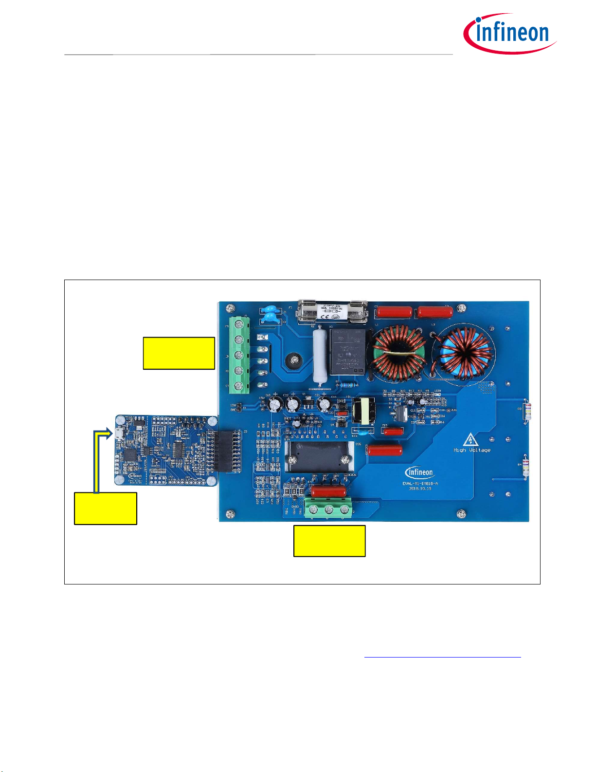
Figure 3 shows the system connection using EVAL-M1-IM818-A and control board (used control board EVALM1-101T for example).
Figure 3 System connection example using EVAL-M1-IM818-A and EVAL-M1-101T
1. Connect PC-USB connector on the on-board-debugger to the PC via USB cable.
2. Connect EVAL-M1-IM818-A’s MADK M1 20-pin interface connector (J3) to control board (see Figure 3).
3. Get the latest “IMC101T-T038 MCE Software Package” available on www.infineon.com/imotion-software
web page. (Infineon iMOTION™ control IC IMC101T-T038 is used for control board EVAL-M1-101T).
4. Connect motor phase outputs to the motor.
5. Use MCEWizard to enter the motor and evaluation board hardware parameters and click button “Export to
Designer file (.txt)” to system drive parameters file which will be used by MCEDesigner.
User Manual 10 <Revision 1.1>
<2019-04-02>
Page 11

Getting Started with EVAL
-M1-
IM818
-A
EVAL-M1-IM818-A User Manual
iMOTION™ Modular Application Design Kit
6. Connect AC power to power input connector (J1) and power on system.
7. Open MCEDesigner and open MCEDesigner default configuration file (.irc) for IMC101T devices
(IMC101T_xx.irc) by clicking “File” menu and select “Open” in the pull down list.
8. Import system drive parameters file (generated in step 5) into MCEDesigner by clicking “File” > “Import
Drive Parameters”. Select “Update All” radio button.
9. Program the MCE Firmware and system parameters into the internal Flash memory of iMOTION™ IC by
clicking “Tools > Programmer “in the pull down menu, and then clicking on the “Program Firmware and
Parameter” radio button. See chapter MCEDesigner setup overview setion 4.2.2 for more details. If the
latest version of MCE firmware is already programmed into the IMC101T-T038 IC, then programming
firmware can be skipped by selecting “Program Parameters” radio button option. Finally click “Start”
button to program firware and parameter (or parameters only when programming firmware was skipped).
10. Start the motor by clicking the green traffic light button in the control bar.
User Manual 11 <Revision 1.1>
<2019-04-02>
Page 12
EVAL-M1-IM818-A User Manual
iMOTION™ Modular Application Design Kit
Getting Started with EVAL-M1-IM818-A
4.2
The iMOTION™ Development Tool installers for MCEDesigner and MCEWizard are available for download via
Infineon iMOTION
software variants are listed there.
On-board debugger uses the SEGGER J-Link’s driver for UART communication with IMC101T-T038. J-Link
driver will be installed during the MCEDesigner installation. In case the driver is not installed properly, please
go to SEGGER J-Link website to download and install the latest J-Link “Software and Documentation pack
for Windows”.
4.2.1
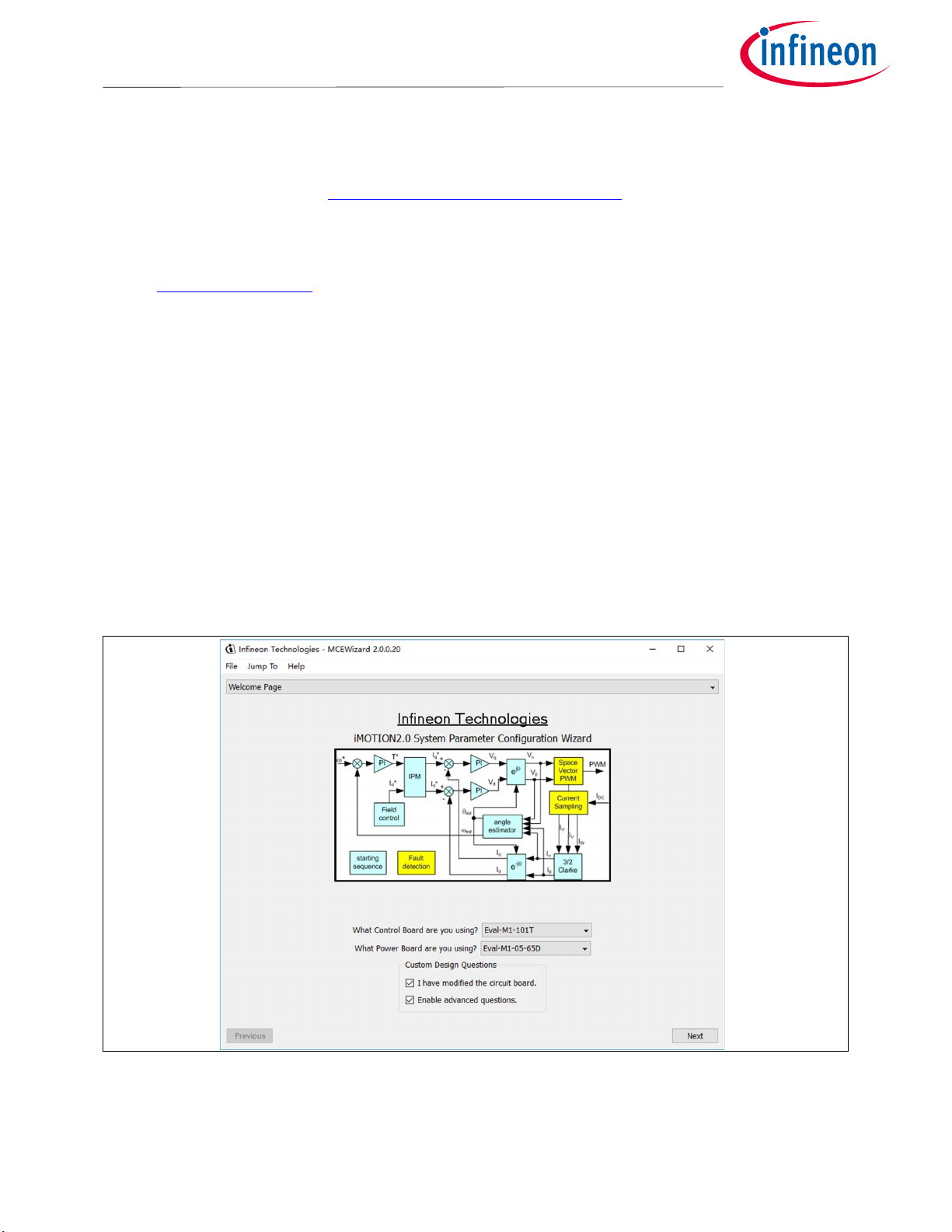
After installing the MCEWizard, the shortcut for MCEWizard appears on the Windows desktop. Double click
the shortcut to open the MCEWizard and configure the parameters for evaluation boards or motor. Figure 4
shows the “Welcome Page” for MCEWizard, where the MADK control board or power board can be selected
through the pull-down list. Infineon keeps releasing new MADK controller and power boards. Therefore, it
could happen that some of the newest power boards are not pre-configured in the MCEWizard tool and
cannot be selected through the pull-down menu. In that case, the user should select any other power board
(as similar as possible) and follow the MCEWizard setup steps by entering the parameter values which are
specific to the chosen board. Make sure both “I have modified the circuit board” and “Enable advanced
question” checkmarks are selected. Please refer to the User Manual of the corresponding power board for
additional information.
iMOTION™ development tools and software
TM
website (http://www.infineon.com/imotion-software). All the available tools and
MCEWizard setup overview
After selecting the MADK control and the power board, start the MCEWizard system setup procedure by
clicking the “Next” button in the right bottom corner as shown in Figure 4.
Figure 4 Welcome Page of MCEWizard
iMOTION™ MADK system enables users to easily test different combination of control and power board with
their motors. User should be familiar with the system level parameters which are related to the motor used.
User Manual 12 <Revision 1.1>
<2019-04-02>
Page 13
Gett
ing Started with EVAL
-M1-
IM818
-A
EVAL-M1-IM818-A User Manual
iMOTION™ Modular Application Design Kit
There are very limited numbers of parameters which are specific to the control board or power board
hardware.
Table 6 provides the MCEWizard setup overview for hardware related parameters specific to EVAL-M1IM818-A power board. Similar tables will be available in each control board’s User Manual. Combination of
this table and the corresponding table of the control board provides enough information to setup the MADKbased motor drive system in shortest time.
Table 6 MCEWizard setup overview table
Page Parameter Value Comment
Welcome Page Control Board selecting EVAL-M1-101T for example
Welcome Page Power Board selecting EVAL-M1-IM818-A If no, select similar
power board to modify
Options Page Motor 1 Shunt Configuration Leg shunt
Question 3 Controller Supply Voltage +3.3V VDD is 3.3V by default
Question 19 Max DC Bus Voltage 820V
Question 23 DC Bus Sensing High Resistor 5000 kΩ
Question 24 DC Bus Sensing Low Resistor Refer to the control board user
manual
Question 54 NTC Temperature Shutdown
value
Question 63 GateSense Low-Side Devices High is true
Question 64 GateSense High-Side Devices High is true
Question 69 Motor 1 Current Input Calculated in the corresponding
Refer to the control board user
manual
Section in control board user
manual
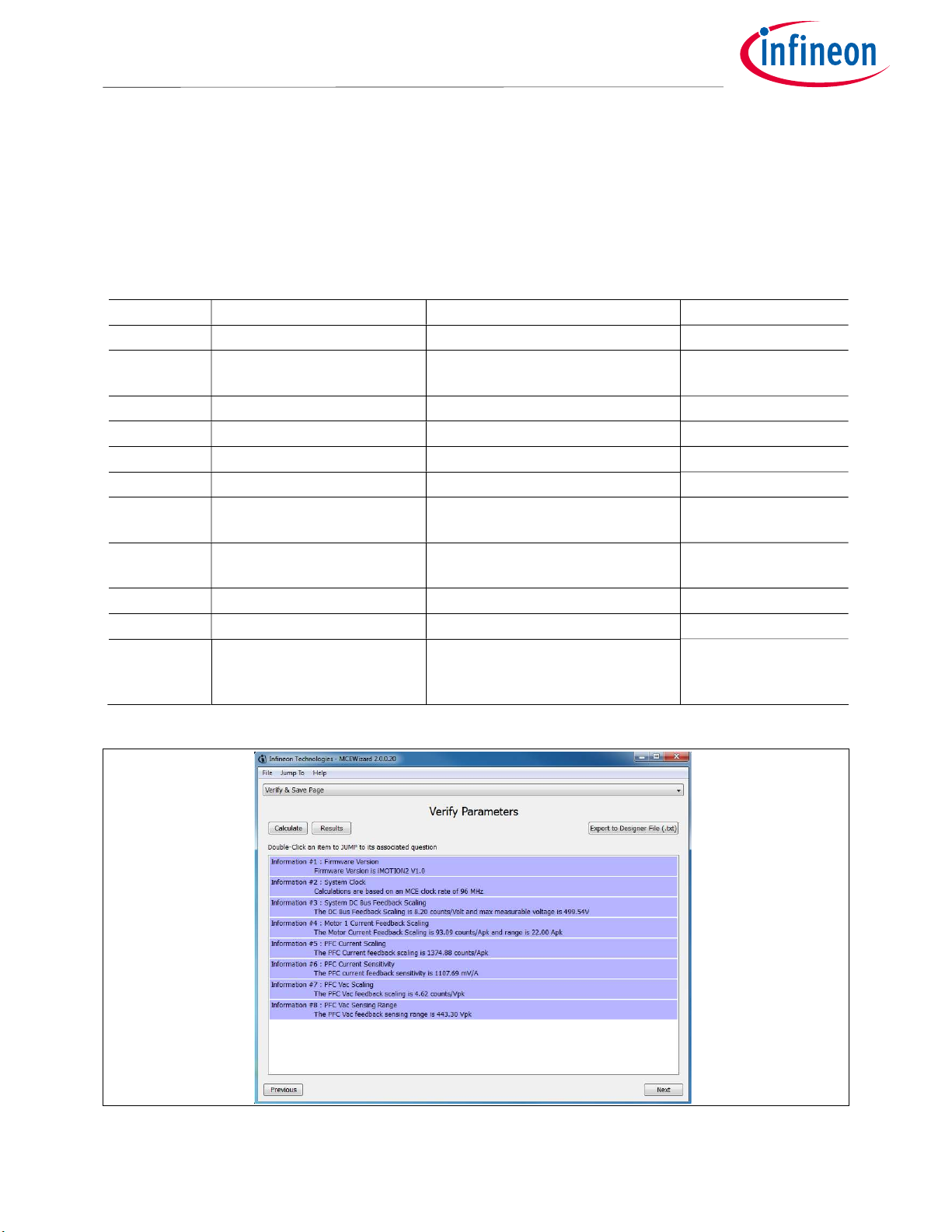
After all the MCEWizard questions are answered, the “Verify & Save Page” will be shown as in Figure 5
Figure 5 Verify and Save page for MCEWizard
User Manual 13 <Revision 1.1>
<2019-04-02>
Page 14

Getting Started with EVAL
-M1-
IM818
-A
EVAL-M1-IM818-A User Manual
iMOTION™ Modular Application Design Kit
Click “Calculate” button and “Export to Designer File (.txt)” button to save the parameter file which will be
used by the MCEDesigner in the next steps.
4.2.2 MCEDesigner setup overview
After installing MCEDesigner installer, there is a shortcut for MCEDesigner on Windows desktop. Double click
the shortcut to open MCEDesigner and then open “IMC101T_xx.irc” file as shown in Table 6.
Figure 6 MCEDesigner’s Main Display for EVAL-M1-101T
To program system drive parameters into IMC101T-T038, please click “Tools” menu and select
“Programmer” in the pull down list. The pop-up window “Program IMC controller” will show up as in Figure
7. Click on the “Program Parameters” radio button (this is the default option), and then select the Drive
System Parameter file created using MCEWizard by clicking on “Browse”. Finally, click on the “Start” button
to program the parameter file into the IMC101T-T038 IC.
Figure 7 “Program IMC Controller” pop-up window
User Manual 14 <Revision 1.1>
<2019-04-02>
Page 15

Getting Started with EVAL
-M1-
IM818
-A
EVAL-M1-IM818-A User Manual
iMOTION™ Modular Application Design Kit
After Drive System Parameter file has been programmed into IMC101 controller, and the motor drive system
is powered, the MCEDesigner can be used to start/stop the motor, display motor current traces, change the
motor speeds, modify drive parameters and many other functions. Please refer to the MCEDesigner
documentation for more details.
Note: On-board Debugger portion of EVAL-M1-101T is galvanically isolated from the controller portion and the
attached power board. In order to program the parameters or firmware to the IMC101T-T038 controller, the
3.3V DC voltage needs to be supplied to the controller portion of the EVAL-M1-101T. This voltage can either
be supplied by the power board (MADK power boards are designed to supply the 3.3V to the control board
through M1 connector) or by feeding the 3.3V DC voltage to the control board through some of the available
3.3V access/test points if the power board is not attached to the EVAL-M1-101T control board.
To program new firmware and Drive System Parameter into IMC101T-T038, please click “Tools” menu and
select “Programmer” in the pull down list. The pop-up window “Program IMC controller” will show up as in
Figure 8. Click on the “Program Firmware and Parameter” radio button, and select the Drive System
Parameter file created using MCEWizard by clicking on the “Browse” button on the row of “Program
Parameter File”, and then select the firmware file by clicking on the “Browse” button on the row of “Program
Firmware File”. Finally, click on the “Start” button to program the parameter file into the IMC101T-T038 IC.
Figure 8 Program Firmware and Parameter in “Program IMC Controller” pop-up window
All the latest firmware files for different types of iMOTIONTM motor control ICs are available for download via
Infineon iMOTION
TM
website (http://www.infineon.com/imotion-software).
User Manual 15 <Revision 1.1>
<2019-04-02>
Page 16

LED1
R11
1M
1M
R9
1M
EVAL-M1-IM818-A User Manual
iMOTION™ Modular Application Design Kit
Hardware description of EVAL-M1-IM818-A
5
To meet individual customer requirements and make the EVAL-M1-IM818-A evaluation board a basis for
development or modification, all necessary technical data like schematics, layout and components are
included in this chapter.
5.1
Pin 14 of connector J3 provides access to the DC-link voltage. Three possible feedback cases are associated
with this pin. Figure 9 provides the DC bus sense resistor details. By default, the resistor R8 is mounted on
EVAL-M1-IM818-A.
Hardware description of EVAL-M1-IM818-A
DC bus Measurement and MCEWizard configuration
+BUS
RED
R5
1M
1M
R8
DCBSENSE
1M
Figure 9 DC bus sense resistor on EVAL-M1-IM818-A evaluation board
The pull down resistor R8 of 1 MΩ referred to ground is inserted on the EVAL-M1-IM818-A evaluation board
to prevent the high BUS voltage +BUS directly connecting to the connector J3. And a pull down resistor of
13.3 Ω for EVAL-M1-101T or 4.87 Ω for EVAL-M1-183M must be inserted on the control board, and then the
DCBSENSE voltage results in the range of 0 to 3.3 V on the pin reflecting a DC bus voltage range of 0 to 400
V.
R10
R12
User Manual 16 <Revision 1.1>
<2019-04-02>
Page 17

Hardware description of EVAL
-M1-
IM818
-A
EVAL-M1-IM818-A User Manual
iMOTION™ Modular Application Design Kit
Figure 10 DC bus sensing configuration in MCEWizard
5.1.1 Motor External Current feedback configuration and calculation
The current input value is product of the shunt resistance in milliohms and gain of External current sense
amplifier for EVAL-M1-101T as shown in Figure 11.
Figure 11 Current shunt feedback and sample timing for EVAL-M1-101T
The external amplifier gain circuit can be found in the schematics or user manual for the control board (For
example, EVAL-M1-101T see Figure 12).
User Manual 17 <Revision 1.1>
<2019-04-02>
Page 18

Hardware description of EVAL
-M1-
IM818
-A
EVAL-M1-IM818-A User Manual
iMOTION™ Modular Application Design Kit
Figure 12 depicts IU+ current feedback sensing circuity on EVAL-M1-101T evaluation board. Please note that
the default external amplification gain is less than 1 for current sense in this evaluation board.
+3.3V
Current Shunt
Resistor on power board
1sh
R6
IU+
10k, 1%
R7 2k, 1% C15
V1 V2 6
R8 100RRsh
iMOTION
Controller
IU
220pF
Figure 12 The part of Current feedback on the EVAL-M1-101T evaluation board
Based on the principle of Kirchhoff's voltage law,
𝑉≈ 𝑉≈(𝑉− 𝐼∗ 𝑅
𝑅
∗
𝑅+ 𝑅
)
𝐶𝑢𝑟𝑟𝑒𝑛𝑡 𝑖𝑛𝑝𝑢𝑡 =
+ 𝐼∗ 𝑅=
𝑅
𝑅+ 𝑅
𝑅+ 𝑅
𝑅=
𝑅
𝑉+
5
𝑅
6
𝑅
𝑅+ 𝑅
𝑅∗ 𝐼
Based on this calculation, the current input for the MADK combination of EVAL-M1-101T and EVAL-M1-IM818-A
is 41.7 mV/A.
Please use same procedure to calculate the current input for other combinations of MADK boards and enter it
into MCEWizard as shown in Figure 13.
User Manual 18 <Revision 1.1>
<2019-04-02>
Page 19

Hardware description of EVAL
-M1-
IM818
-A
EVAL-M1-IM818-A User Manual
iMOTION™ Modular Application Design Kit
Figure 13 Current feedback configuration in MCEWizard for EVAL-M1-101T and EVAL-M1-IM818-A
User Manual 19 <Revision 1.1>
<2019-04-02>
Page 20

Hardware description of EVAL
-M1-
IM818
-A
EVAL-M1-IM818-A User Manual
iMOTION™ Modular Application Design Kit
5.2 EMI filter and soft power up circuit
Figure 14 depicts the schematic from the AC line input connector J1 to the rectified DC bus voltage. This
circuitry includes a passive EMI filter consisting of elements C1, C2, L1, L2 and a 40 A/1200 V rectifier block
DB, a fuse F1 for inrush current protection, and a relay K1 for soft powering up and reducing conduction
losses in steady state. Four electrolytic capacitors C6, C7, C8 and C9 are used for buffering the rectified DC
bus voltage DCP.
J1
5
4
3
2
1
CON7
DB1
2
A
3
GUO40-12NO1
5
P
15V
B
4
C
1
N
R2
100ohm 10W
R1
27R 0.5W
T9GV1L14-12
ZTPV-25 30A1000V
F1
K1
C1
2200pF 4kVC22200pF 4kV
C5
104 1000V
L1
1 2
2 mH, 10A
34
L2
220uH, 7.1A
C6
470uF, 450VC7470uF, 450V
C3
104 1000V
C8
470uF, 450VC9470uF, 450V
GND1
DCBUS
R3
270k 1W
R4
270k 1W
Figure 14 Schematic for EMI filter and AC/DC section of the EVAL-M1-IM818-A evaluation board
C4
104 1000V
User Manual 20 <Revision 1.1>
<2019-04-02>
Page 21
Hardware description of EVAL
-M1-
IM818
-A
EVAL-M1-IM818-A User Manual
iMOTION™ Modular Application Design Kit
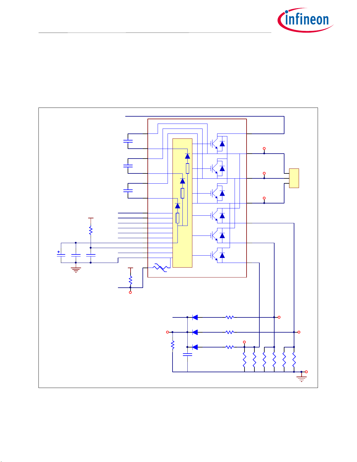
5.3 Inverter section using CIPOS™ Maxi IPM
The inverter section is implemented using the CIPOS™ Maxi IPM as sketched in Figure 15. The module
includes an optimized SOI gate driver and three phase inverter with 1200V TRENCHSTOP™ IGBTs and Emitter
Controlled diodes.
The three capacitors C10, C11 and C12 are used as bootstrap capacitors to provide the necessary floating
supply voltages V
BS1
, V
BS2
and V
respectively.
BS3
+BUS
M1
C23
47uF, 25V
15V
C17
10uF
3.3V
R20
100K
C30
4700p
C10
22uF 25V
C11
22uF 25V
C12
22uF 25V
PWMUH
PWMVH
PWMWH
PWMUL
PWMVL
PWMWL
GK
ITRIP
VTH
3.3V
VTH
R21
TBD
1
2
3
4
5
6
7
8
9
10
11
12
13
14
15
16
17
CIPOS MAXI
24
U
IW
U
J2
V
V
W
W
IV
3
2
1
CON3
IU
23
22
21
20
19
18
Figure 15 Schematic of the 3-phase inverter section using CIPOS™ Maxi IPM on EVAL-M1-IM818-A
User Manual 21 <Revision 1.1>
<2019-04-02>
ITRIP
ITRIP
R31
10K
C31 102 50V
D8
BAS3005A
D9
BAS3005A
D10
BAS3005A
R32
1K
R33
1K
R34
1K
RSW1
50mR
IW
RSW2
50mR
RSV1
50mR
RSV2
50mR
IV
IU
RSU2
50mR
GND3
RSU1
50mR
Page 22
Hardware description of EVAL
-M1-
IM818
-A
EVAL-M1-IM818-A User Manual
iMOTION™ Modular Application Design Kit
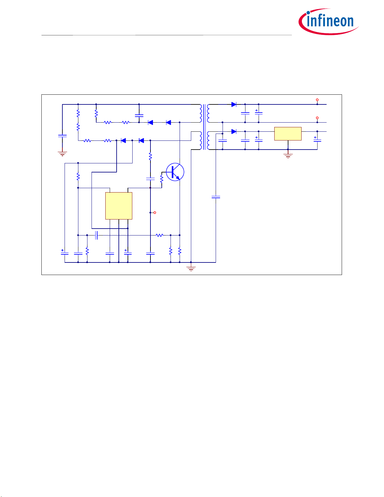
5.4 Auxiliary power supply
Figure 16 depicts the schematic of the auxiliary power supply available on the EVAL-M1-IM818-A board. The
circuit includes IRS2505L that is used to generate 15 V directly from the DC bus. VCC is connected to the gate
drivers inside the CIPOS™ IPM.
TB1
*
*
EF16
32
Q1
R39
4.3R
*
*
D4
10BQ100
104 63V
C19
102 1kV
D5
10BQ100
C20
10uF
C14
C16
10uF
C35
104 1000V
C34
10uF, 50V
+BUS
C37
102
R6
1M
R13
1M
R14
1M
R22
3.3K
R18
56K
C33 474
R23
1.2K
R19
56K
R15
1M
5
R17
56K
D3
BAV19
VBUS
CMP1COM2Vcc
C15
103
47uF, 50V
C13 223 630V
D2
BAV19
4
N1
IRS2505L
PFC
3
C32
D1
STTH112
C36
222
R16
1.5K
R7 24R
ZVS
R24
1.5K
C38
682
D6
STTH112
1
STP3N150
R38
4.3R
Figure 16 Power supply section of the EVAL-M1-IM818-A evaluation board
C18
470uF, 50V
0V
6V
1
0V
C21 470uF, 16V
15V 0.3A
Vin
U1 IFX1117ME V33
3
Vout
GND
2
15V
15V
GND2
3.3V
C22
470uF, 16V
The linear voltage regulator IFX1117ME V33 generates 3.3 V from 15 V power supply VCC. Both VCC and 3.3 V
are also present on the 20 pin interface connector J2 to power circuitry on the controller board
User Manual 22 <Revision 1.1>
<2019-04-02>
Page 23

Hardware description of EVAL
-M1-
IM818
-A
EVAL-M1-IM818-A User Manual
iMOTION™ Modular Application Design Kit
5.5 Schematic with EVAL-M1-IM818-A evaluation board
Figure 17 displays schematic with EVAL-M1-IM818-A board
J1
CON7
104 1000V
10uF, 50V
DB1
2
+BUS
C37
102
A
GUO40-12NO1
R6
1M
R13
1M
R141MR15
R22
3.3K
C33 474
R23
1.2K
3
B
4
R18
56K
R19
56K
1M
5
VBUS
CMP1COM2Vcc
C15
103
5
4
3
2
1
C35
C34
P
15V
C
N
R17
56K
D3
BAV19
47uF, 50V
5
R1
27R 0.5W
T9GV1L14-12
1
C13 223 630V
D2
BAV19
4
N1
IRS2505L
PFC
3
C32
R2
100ohm 10W
2200pF 4kVC22200pF 4kV
D1
STTH112
R16
1.5K
C36
222
R7 24R
ZVS
R24
1.5K
C38
682
K1
C1
D6
STTH112
1
STP3N150
R38
4.3R
F1
104 1000V
32
C5
R39
4.3R
Q1
TB1
*
***
EF16
L1
1 2
2 mH, 10A
10BQ100
104 63V
102 1kV
ZTPV-25 30A1000V
D4
C20
C19
34
10uF
D5
10BQ100
CON2
L2
220uH, 7.1A
470uF, 450VC7470uF, 450V
C3
104 1000V
470uF, 450VC9470uF, 450V
GND1
UH
VH
WH
UL
VL
WL
C14
C16
10uF
C21 470uF, 16V
J4
15V
2
0V
1
Go Fan Cooling
C6
C8
R8
DCBSENSE
1M
PWMUH
PWMVH
PWMWH
PWMUL
PWMVL
PWMWL
C18
470uF, 50V
0V
6V
1
Vin
U1 IFX1117ME V33
0V
2
J3
+15V
CON20
DCBUS
R3
270k 1W
R4
270k 1W
R10
R9
1M
1M
15V
C23
47uF, 25V
15V
15V
15V 0.3A
GND2
3
3.3V
Vout
GND
C22
470uF, 16V
PWMUH
1
UH
2
GND
PWMUL
3
UL
GND
4
GND
PWMVH
5
VH
6
VDD
PWMVL
7
VL
3.3V
8
VDD
PWMWH
9
WH
IU+
10
IU+
PWMWL
11
WL
IU-
12
IU-
GK
13
GK
DCBSENSE
14
DCB
VTH
15
VTH
IV+
16
IV+
IV-
17
IV-
IW+
18
IW+
IW-
19
IW-
15V
20
C4
104 1000V
C17
10uF
GND
3.3V
+BUS
R5
1M
R11
1M
R12
1M
3.3V
R20
100K
C30
4700p
3.3V
GK
LED1
RED
22uF 25V
22uF 25V
22uF 25V
C10
C11
C12
PWMUH
PWMVH
PWMWH
PWMUL
PWMVL
PWMWL
GK
ITRIP
VTH
VTH
R25
100R
R27
100R
R28
100R
M1
1
2
3
4
5
6
7
8
9
10
11
12
13
14
15
16
3.3V
17
R21
CIPOS MAXI
TBD
ITRIP
ITRIP
R31
10K
C31 102 50V
34
L3
C24
332
1 2
150uH
34
L4
C26
332
1 2
150uH
34
L5
C27
332
1 2
150uH
BAS3005A
BAS3005A
BAS3005A
C25
332
C28
332
C29
332
24
U
U
23
J2
3
V
V
22
21
20
19
IW
18
R32
D8
1K
R33
D9
1K
IW
R34
D10
1K
RSW1
50mR
RSW2
50mR
IU
R26
100R
IV
R29
100R
IW
R30
100R
RSV1
50mR
2
1
CON3
W
W
IU
IV
IV
IU
RSU2
50mR
GND3
RSV2
RSU1
50mR
50mR
Figure 17 Schematic on the EVAL-M1-IM818-A evaluation board
User Manual 23 <Revision 1.1>
<2019-04-02>
Page 24

Hardware description of EVAL
-M1-
IM818
-A
EVAL-M1-IM818-A User Manual
iMOTION™ Modular Application Design Kit
5.6 PCB Layout
The layout of this board can be used for different voltage or power classes. The PCB has two electrical layers
with 35µm copper by default and its size is 197 mm × 140 mm. The PCB board thickness is 1.6mm. Get in
contact with our technical support team to get more detailed information and the latest Gerber-files.
Figure 18 illustrates the top assembly print of the evaluation board.
Figure 18 Top assembly print of the EVAL-M1-IM818-A evaluation board
User Manual 24 <Revision 1.1>
<2019-04-02>
Page 25

Hardware description of EVAL
-M1-
IM818
-A
EVAL-M1-IM818-A User Manual
iMOTION™ Modular Application Design Kit
Figure 19 depicts the bottom assembly print of the evaluation board.
Figure 19 Bottom assembly print of the EVAL-M1-IM818-A evaluation board
User Manual 25 <Revision 1.1>
<2019-04-02>
Page 26

Hardware description of EVAL
-M1-
IM818
-A
EVAL-M1-IM818-A User Manual
iMOTION™ Modular Application Design Kit
The top layer routing of the PCB is provided in Figure 20.
Figure 20 Top layer routing of the EVAL-M1-IM818-A
User Manual 26 <Revision 1.1>
<2019-04-02>
Page 27

Hardware description of EVAL
-M1-
IM818
-A
EVAL-M1-IM818-A User Manual
iMOTION™ Modular Application Design Kit
Figure 21 illustrates the bottom layer routing of the PCB.
Figure 21 Bottom layer routing of the EVAL-M1-IM818-A
User Manual 27 <Revision 1.1>
<2019-04-02>
Page 28

Bill of Materials of EVAL
-M1-
IM818
-A
EVAL-M1-IM818-A User Manual
iMOTION™ Modular Application Design Kit
6 Bill of Materials of EVAL-M1-IM818-A
Table 7 provides the complete bill of materials of the evaluation board.
Table 7 Bill of materials
No. Qty Part description Designator Part number Manufacturer
1 2 CAP CER 2200PF 4KV X7R 2220 C1, C2 HV2220Y222JXVATHV Vishay Vitramon
2 4 CAP FILM 0.1UF 5% 1KVDC
RADIAL
3 4 CAP ALUM 470UF 20% 450V SNAP C6, C7, C8,
4 3 CAP CER 22UF 16V X5R 1206 C10, C11,
5 1 CAP CER 0.033μF 630V X7R C13 890303322005CS Wurth Electronics Inc.
6 3 CAP CER 10μF 25V X5R 0805 C14, C16,
7 1 CAP CER 0.01μF 50V X7R 0805 C15 885012207092 Wurth Electronics Inc.
8 1 CAP ALUM 470UF 20% 50V
RADIAL
9 1 CAP ALUM 47UF 20% 50V RADIAL C32 860020673013 Wurth Electronics Inc.
10 1 CAP CER 1000PF 1KV RADIAL C19 CK45-R3AD102K-NRA TDK Corporation
11 1 CAP FILM 0.1UF 10% 63VDC
RADIAL
13 2 CAP ALUM 470UF 20% 16V
RADIAL
14 1 CAP ALUM POLY 47UF 20% 25V
T/H
15 6 CAP CER 3300PF 50V C0G/NP0
0805
16 2 CAP CER 4700PF 50V C0G/NP0
0805
17 2 CAP CER 1000PF 50V C0G/NP0
0805
18 1 CAP CER 0.47UF 50V X7R 0805 C33 885012207102 Wurth Electronics Inc.
19 1 CAP ALUM 10UF 20% 25V RADIAL C34 860020472003 Wurth Electronics Inc.
20 1 CAP CER 2200PF 50V C0G/NP0
0805
21 2 DIODE GEN PURP 1.2KV 1A SMA D1, D6 STTH112A STMicroelectronics
22 2 DIODE GEN PURP 100V 200MA
SOD123
23 2 DIODE SCHOTTKY 100V 1A SMB
C3, C4, C5,
C35
C9
C12
C17
C18,
C20
C21, C22
C23
C24, C25,
C26, C27,
C28, C29
C30, C38
C31, C37
C36
D2, D3
D4, D5
B32653A0104K189 EPCOS (TDK)
861221486023 Wurth Electronics Inc.
885012108018 Wurth Electronics Inc.
C2012X5R1E106M125
AB
860020675022 Wurth Electronics Inc.
B32529C0104K189 TDK Corporation
860020374012 Wurth Electronics Inc.
870025574002 Wurth Electronics Inc.
885012007066 Wurth Electronics Inc.
885012007067 Wurth Electronics Inc.
885012007063 Wurth Electronics Inc.
885012007065 Wurth Electronics Inc.
BAV19W-7-F
10BQ100 Vishay
TDK Corporation
Diodes Incorporated
Semiconductor
Diodes Division
User Manual 28 <Revision 1.1>
<2019-04-02>
Page 29

Bill of Materials of EVAL
-M1-
IM818
-A
EVAL-M1-IM818-A User Manual
iMOTION™ Modular Application Design Kit
No. Qty Part description Designator Part number Manufacturer
24 1 3-PHASE BRIDGE RECT 1200V 40A DB GUO40-12NO1 IXYS
25 1 FUSE CERAMIC 32A 1000VDC F1 ZTPV-32 LKET
26 1 CONN TERM BLOCK 5POS 9.52MM
PCB
27 1 CONN TERM BLOCK 3POS 9.52MM
PCB
28 1 CONN RCPT .100" 20PS DL R/A
GOLD
29 1 CONN HEADER 2 POS 2.54 J4 61300211121 Wurth Electronics Inc.
30 1 RELAY GEN PURPOSE SPST 30A
12V
31 1 8103-RC L1 JWMILLER_8103 Bourns Inc.
32 1 220uH 7.1A L2 NPH130060 Poco Holding
33 3 WE-CNSW SMD Common Mode
Line Filter
34 1 LED RED CLEAR 0805 SMD LED1 150080RS75000 Wurth Electronics Inc.
35 7 MOSFET N-CH 1500V 2.5A TO-220 Q1 STP3N150 STMicroelectronics
36 1 RES 27 OHM 1/2W 5% AXIAL R1 CFR-50JB-52-27R Yageo
37 1 RES 100 OHM 10W 5% AXIAL R2 PNP10VJT-91-100R Yageo
38 2 RES 270K OHM 1W 5% AXIAL R3, R4 FMP100JR-52-270K Yageo
39 10
RES SMD 1M OHM 0.1% 1/8W
0805
40 1 RES SMD 24 OHM 5% 1/4W 1206 R7 RC1206JR-0724RL Yageo
41 2 RES SMD 1.5K OHM 1% 1/10W
0805
42 3 RES SMD 75K OHM 0.5% 1/4W
1206
43 1 RES SMD 100K OHM 1% 1/8W
0805
44 1 DNI R21 RC0603JR-07110KL Yageo
45 2 RES SMD 10K OHM 5% 1/8W 0805 R22, R31 RC0805JR-0710KL Yageo
46 1 RES SMD 3.9K OHM 0.1% 1/8W
0805
47 6
RES SMD 100 OHM 1% 1/8W 0805
48 3
RES SMD 1K OHM 1% 1/8W 0805
J1
J2
J3
K1
L3, L4, L5
R5, R6, R8,
R9, R10,
R11, R12,
R13, R14,
R15
R16, R24
R17, R18,
R19
R20
R23
R25, R26,
R27, R28,
R29, R30
R32, R33,
R34
691250910003
691250910002
691250910003 Wurth Electronics Inc.
613020243121 Wurth Electronics Inc.
T9GV1L14-12 TE Connectivity
744232101 Wurth Electronics Inc.
RG2012P-105-B-T5 Yageo
RT0805FRE071K5L Yageo
RT1206DRD0775KL Yageo
RC0805FR-07100KL Yageo
RT0805BRD073K9L Yageo
RC0805FR-07100RL Yageo
RC0805FR-071KL Yageo
Wurth Electronics Inc.
Potter & Brumfield
Relays
User Manual 29 <Revision 1.1>
<2019-04-02>
Page 30

Bill of Materials of EVAL
-M1-
IM818
-A
EVAL-M1-IM818-A User Manual
iMOTION™ Modular Application Design Kit
No. Qty Part description Designator Part number Manufacturer
49 2 RES SMD 4.3 OHM 1% 1/4W 1206 R38, R39 RC1206FR-074R3L Yageo
50 6
RES 0.05 OHM 1W 1812 WIDE
51 1 Transformer EE16-10P TB1 EE16-10P 52 22
TEST POINT PC MAXI .040""D RED
53 1 IC REG LINEAR 3.3V 1A SOT223-4 U1 IFX1117MEV33HTMA1 Infineon Technologies
RSU1,
RSU2, RSV1,
RSV2,
RSW1,
RSW2
3.3V, 15V,
DCBUS, GK,
GND1,
GND2,
GND3,
ITRIP, IU, IV,
IW, U, UH,
UL, V, VH,
VL, VTH, W,
WH, WL,
ZVS
RL1218JK-070R05L Yageo
5001 Keystone Electronics
54 3 DIODE SCHOTTKY 30V 500MA
SC79-2
55 1 1200 V, 3-phase Intelligent Power
Module
56 1 IC PFC MOSFET SOT-23-5 N1 IRS2505LTRPBF Infineon Technologies
D8, D9, D10 BAS3005A02VH6327X
TSA1
M1 IM818-MCC Infineon Technologies
Infineon Technologies
User Manual 30 <Revision 1.1>
<2019-04-02>
Page 31

Reference
EVAL-M1-IM818-A User Manual
iMOTION™ Modular Application Design Kit
7 Reference
[1] Datasheet of Infineon CIPOS™ Maxi IM818, is available for download on Infineon’s website
https://www.infineon.com/cms/en/product/power/intelligent-power-modules-ipm/cipos-maxi/
[2] Application Note AN2016-10 CIPOS Maxi Technical Description, is available for download on Infineon’s
website
Note: All listed reference materials are available for download on Infineon’s website
www.infineon.com/.
All the iMOTION MADK evaluation board’s User Manuals are available at
www.infineon.com/MADK
User Manual 31 <Revision 1.1>
<2019-04-02>
Page 32

EVAL-M1-IM818-A User Manual
iMOTION™ Modular Application Design Kit
Table of Contents
Revision History
Major changes since the last revision
Version number Revision Date Revision description
1.0 2018-11-15 First release
1.1 2019-04-02 Change output power to 1500W and Current to 2.35A.
Optimization schematic
User Manual 32 <Revision 1.1>
<2019-04-02>
Page 33

EasyPIM™,
ISOFACE™, IsoPACK™,
OptiMOS™, ORIGA™, POWERCODE™, PRIMARION™, PrimePACK™,
TEMPFET™,
Manual
technology,
prices please
ffice
Due to technical requirements products may contain
dangerous substances. For information on the types
contact your nearest Infineon
Except as otherwise explicitly approved by Infineon
Technologies in a written document signed by
authorized representatives of Infineon
Technologies, Infineon Technologies’ products may
applications where a failure of the
product or any consequences of the use thereof can
Trademarks of Infineon Technologies AG
AURIX™, C166™, CanPAK™, CIPOS™, CoolGaN™, CoolMOS™, CoolSET™, CoolSiC™, CORECONTROL™, CROSSAVE™, DAVE™, DI-POL™, DrBlade™,
EconoBRIDGE™, EconoDUAL™, EconoPACK™, EconoPIM™, EiceDRIVER™, eupec™, FCOS™, HITFET™, HybridPACK™, Infineon™,
i-Wafer™, MIPAQ™, ModSTACK™, my-d™, NovalithIC™, OmniTune™, OPTIGA™,
PrimeSTACK™, PROFET™, PRO-SIL™, RASIC™, REAL3™, ReverSave™, SatRIC™, SIEGET™, SIPMOS™, SmartLEWIS™, SOLID FLASH™, SPOC™,
thinQ!™, TRENCHSTOP™, TriCore™.
Trademarks updated August 2015
Other Trademarks
All referenced product or service names and trademarks are the property of their respective owners.
Edition <2019-04-02>
Published by
Infineon Technologies AG
81726 Munich, Germany
© 2019 Infineon Technologies AG.
All Rights Reserved.
Do you have a question about this
document?
Email: erratum@infineon.com
AN2018-35 EVAL-M1-IM818-A User
Document reference
IMPORTANT NOTICE
The information contained in this application note is
given as a hint for the implementation of the product
only and shall in no event be regarded as a
description or warranty of a certain functionality,
condition or quality of the product. Before
implementation of the product, the recipient of this
application note must verify any function and other
technical information given herein in the real
application. Infineon Technologies hereby disclaims
any and all warranties and liabilities of any kind
(including without limitation warranties of noninfringement of intellectual property rights of any
third party) with respect to any and all information
given in this application note.
The data contained in this document is exclusively
intended for technically trained staff. It is the
responsibility of customer’s technical departments
to evaluate the suitability of the product for the
intended application and the completeness of the
product information given in this document with
respect to such application.
For further information on the product,
delivery terms and conditions and
contact your nearest Infineon Technologies o
(www.infineon.com).
WARNINGS
in question please
Technologies office.
not be used in any
reasonably be expected to result in personal injury.
 Loading...