

Mark eting Informati on
D 721 S
C
±
ø3,5
A
Euro pean PowerSemicondu cto r and
Electronics Compan y
0,1
-
48
-0,2
75
Applikation: Freilau fdiode in Spannu ngszwisch enkreisumrich ter
bis V
D(DC )
= 2 0 00 V
VWK January

Schnelle Gleichrichterdiode
D 721 S 45 T
Elektrische Eigenschaften / Electrical properties
1)
1)
1)
Thermische Eigenschaften / Thermal properties
Mechanische Eigenschaften / Mechanical properties
Fast Diode
Höchstzulässige Werte / Maximum rated values
Periodische Spitzensperrspannung 3500 V, 4000V
repetitive peak reverse voltage tvj = -40°C...125°C V
RRM
Stoßspitzensperrspannung 3600 V, 4100V
non-repetitive peak reverse voltage tvj = +25°C...125°C V
Durchlaßstrom-Grenzeffektivwert / RMS forward current I
Dauergrenzstrom / mean forward current tC = 85°C I
RSM
FRMSM
FAVM
tC = 52°C 1080 A
Stoßstrom-Grenzwert
surge forward current
Grenzlastintegral t
t
= 25°C I
vj
FSM
tvj = 125°C 15000 A
= 25°C I²t 1,3x10⁶A²s
vj
I²t-value tvj = 125°C 1,13x10⁶A²s
Kritische periodische Ausschaltstromsteilheit t
= 125°C, IFM = 2000 A, VR = 3000 V (-di/dt)
vj
com
critical repetitive rate of fall of on - state C = 0,25 µF, R = 6 Ω
Charakteristische Werte / Characteristic values
Gleichsperrspannung / cont. direct reverse voltage tc = -40°C ... +85°C V
Durchlaßspannung / forward voltage tvj = 125°C iFM = 2500 A V
Schleusenspannung / threshold voltage tvj = 125°C V
Ersatzwiderstand / forward slope resistance tvj = 125°C r
Sperrstrom / reverse current tvj = 125°C, vR = 0,67 V
tvj = 125°C, vR = V
RRM
RRM
Rückstromspitze / peak reverse recovery current iFM = 1000 A, -diF/dt = 250 A/µs I
tvj = 125 °C; vR = 1000 V;
C = 0,25 µF; R = 6 Ω
Sperrverzögerungsladung iFM = 1000 A, -diF/dt = 250 A/µs Q
recovered charge tvj = 125 °C; vR = 1000 V;
C = 0,25 µF; R = 6 Ω
R(D)
F
(TO)
T
i
R
RM
rr
4500 V
4600 V
1700 A
720 A
16000 A
500 A/µs
typ. 2000V
3,5 V
1,7 V
0,69 mΩ
ca. 75 mA
140 mA
600 A
1700 µAs
Innerer Wärmewiderstand Kühlfläche / cooling surface R
thJC
thermal resistance, junction to case beidseitig / two-sided 0,018 K/W
Anoden / anode 0,033 K/W
Kathode / cathode 0,04 K/W
Übergangs-Wärmewiderstand Kühlfläche / cooling surface R
thCK
thermal resistance, case to heatsink beidseitig / two-sided 0,005 K/W
einseitig / single-sided 0,01 K/W
Höchstzul. Sperrschichttemp. / max. junction temperat. tvjmax 125 °C
Betriebstemperatur / operating temperature tc op -40...+125°C
Lagertemperatur / storage temperature t
stg
-40...+150°C
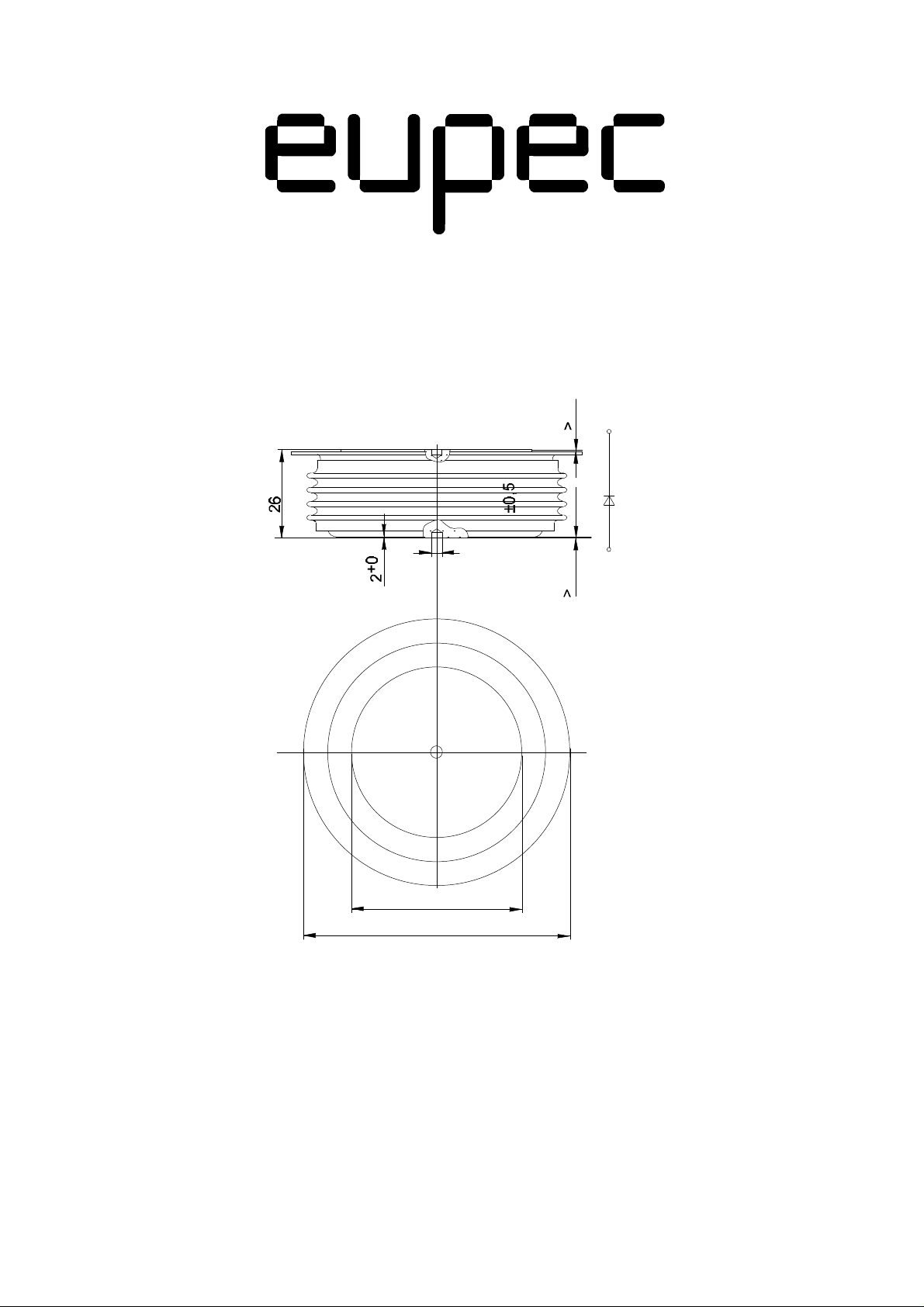
Gehäuse, siehe Anlage / case, see appendix Seite / page 1
Anpreßkraft /clamping force F 15...36 kN
Gewicht / weight G ca. 600 g
Luftstrecke / air distance ca. 20 mm
Kriechstrecke / creepage distance 30 mm
Feuchteklasse / humidity classification DIN 40040 C
Schwingfestigkeit / vibration resistance f = 50 Hz 50 m/s²
Mit dieser technischen Information werden Halbleiterbauelemente spezifiziert, jedoch keine Eigenschaften zugesichert. Sie gilt
in Verbindung mit den zugehörigen Technischen Erläuterungen.
This technical information specifies semiconductor devices but promises no characteristics. It is valid in combination with the
belonging technical notes.
1) Richtwert für obere Streubereichsgrenze / Upper limit of scatter range (standart value)
D 721 S
4000
i
F
[A]
3000
2000
1000
0
1,0 1,5 2,0 2,5 3,0 3,5 4,0 4, 5
vF [V]
D 721 S_01
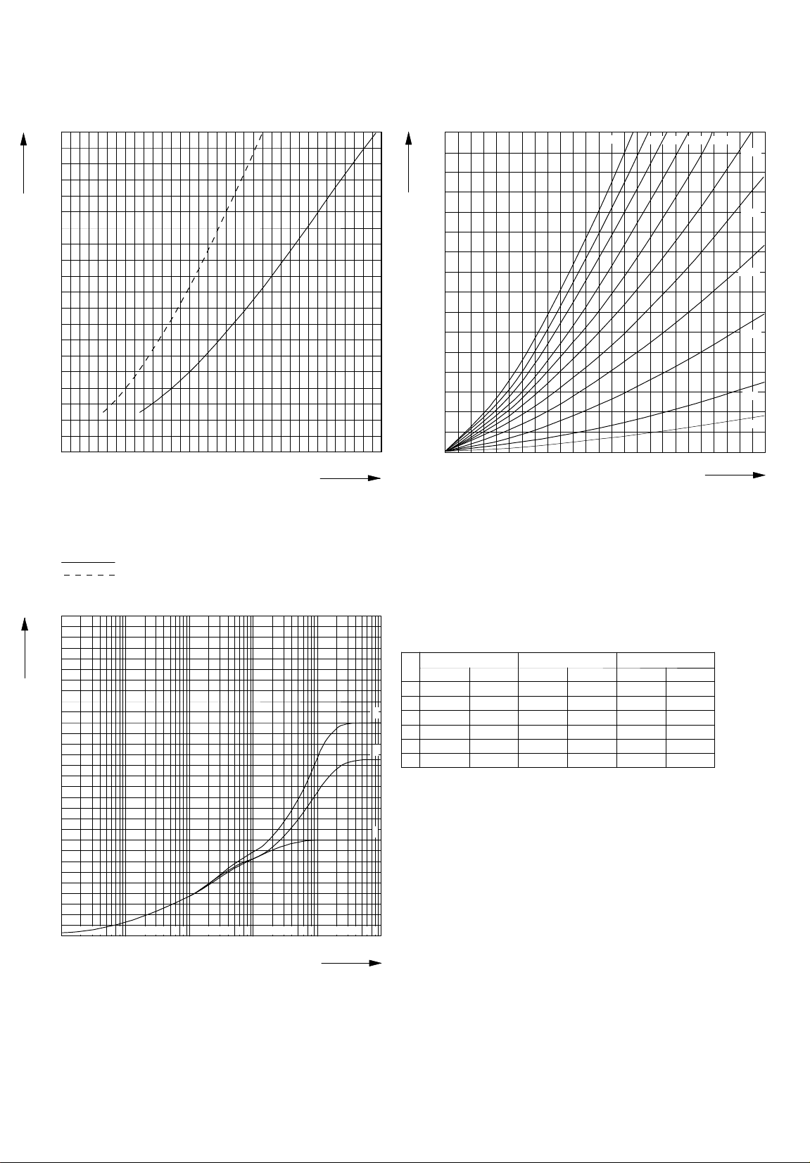
Fig. 1
On- state characteristic iF = f(VF)
tvj = 125°C
Upper limit of scatter range
Lower limit of scatter range
4000
3500
P
FAV
[W]
3000
2500
2000
1500
1000
500
0
D 721 S_02
500 1000 1500 2000 2500
Fig. 2
On-state losses (aver age values)
IF = f(P
tvj = 125 °C
FAV
90%80% 70%100% 60%
50%
40%
30%
20%
10%
5%
IF [A]
)
0,06
0,05
Z
thJC
[K/W]
0,04
0,03
0,02
0,01
2 3 4 6 8 2 3 4 6 8 2 3 4 6 8 2 3 4 6 8 2 3 4 6 8
0
0,001 0,01 0,1 1 10 100
t [s]
D 721 S_03
Fig. 3
Transient thermal impedance Z
1 - Two-sided cooling
= f(t), DC
thJC
2 - Anode-sided cooling
3 - Cathode-sided cooling
Analytical elements of transient ther mal impedance Z
1. Z
thJC
2. Z
thJC
r [K/W]τ [s] r [K/W]τ [s] r [K/W]τ [s]
1 0,00637 1,80000 0,02137 8,00000 0,02837 6, 80000
2 0,00904 0,14000 0,00904 0,14000 0,00904 0, 14000
3
3 0,00267 0,01410 0,00167 0,01410 0,00167 0, 01410
4 0,00080 0,00265 0,00080 0,00265 0,00080 0, 00265
5 0,00012 0,00067 0,00012 0,00067 0,00012 0, 00067
2
Σ
0,00180 - 0,03300 - 0,04000 -
Analytical function:
n
max
1
ZthJC = Σ R
n = 1
(1-EXP(-t/τn))
thn
3. Z
thJC
thJC
for DC

D 721 S
100
8
6
5
4
I
FSM
3
[kA]
2
10
8
6
5
4
3
2
1
0,1 1 1 10
1
T = Hz
50
Sine half wave 50Hz
5 6 8 2 3 4 5 6 842 3 4 5 6 8 2 3
tp [ms]
D 721 S_05
Fig. 4
Sur ge Current I
I
= f(tp)
FSM
= f(Sine half wave)
FSM
tvj = 125°C
VR = 0
0,008
0,007
∆
rth
[K/W]
f = 50Hz
f = 60Hz
0,006
0,005
0,004
f = 100Hz
0,003
I
FSM
tp
0,002
f = 200Hz
0,001
f = 500Hz
0
10 20 30 40 50 60 70 80 90 100
D 721 S_04
ED [ %]
λ [°el]
Fig. 5
∆ rth = f ( ED, Frequency)
Two-sided cooling
Current wave form: square wave
Parameter: frequency
1000
I
RM
[A]
100
10
9
7
5
4
3
2
9
7
5
4
3
2
3000A
2000A
1000A
600A
300A
100A
I
FM
-di/dt
Q
rr
I
RM
2 3 4 5 6 7 8 92 3 4 5 6 7 8 9
10 100 1000
-di/dt [A/µs]
D 721 S_06
Fig. 6
Reverse r ecovery current (upper-limit , ca. 98% values)
Application: GTO-freewheeling diode
Parameter: I
t
vj
R
FM
≤ 125°C; CS ≥ 4µF
= 0 Ω; V
> 2000 V ... 3000 V
S
R
1000
9
7
5
I
RM
4
[A]
3
2
100
9
7
5
4
3
2
V
R
10
3000A
2000A
1000A
600A
300A
100A
I
FM
-di/dt
Q
rr
V
I
RM
2 3 4 5 6 7 8 92 3 4 5 6 7 8 9
R
10 100 1000
-di/dt [A/µs]
D 721 S_07
Fig. 7
Reverse r ecovery current (lower-limit, ca. 2% values)
Application: G TO-freewheeling diode
Parameter: I
t
vj
R
FM
≤ 125°C; CS ≥ 4µF, Diode D291S
= 0 Ω; V
S
> 2000 V ... 3000 V
R

D 721 S
1000
9
7
5
4
Q
rr
[µAs]
100
10
3
2
9
7
5
4
3
2
2 3 4 5 6 7 8 9 2 3 4 5 6 7 8 9
IFM = 3000A
2000A
1000A
600A
300A
100A
I
FM
-di/dt
Q
rr
I
RM
10 100 1000
-di/dt [A/µs]
D 721 S_08
Fig. 8
Reverse r ecovery charge ( upper limit, ca. 98% values)
Application: GTO-fr eewheeling diode
Par ameter: I
tvj ≤ 125°C; CS ≥ 4µF
RS = 0 Ω; VR > 2000 V ... 3000 V
FM
1000
9
7
I
FM
5
Q
rr
[µAs]
100
V
R
-di/dt
4
3
2
9
7
5
4
3
2
10
Q
rr
V
I
RM
2 3 4 5 6 7 8 9 2 3 4 5 6 7 8 9
R
IFM = 3000A
2000A
1000A
600A
300A
100A
10 100 1000
-di/dt [A/µs]
D 721 S_09
Fig. 9
Reverse r ecovery charge ( lower limit, ca. 2% values)
Application: GTO-freewheeling diode
Par ameter: I
tvj ≤ 125°C; CS ≥ 4µF
RS = 0 Ω; VR > 2000 V ... 3000 V
FM
10
9
7
5
E
off
4
[Ws]
3
2
1
9
7
5
4
0,1
3
2
2 3 4 5 6 7 8 9 2 3 4 5 6 7 8 9
I
FM
-di/dt
Q
rr
I
RM
10 100 1000
-di/dt [A/µs]
D 721 S_13
Fig. 10
Turn-of f - losses E
diodes with VFmax
Application: GTO-freewheeling diode
Parameter:IFM; Snubber diode D 291 S
tvj = 125°C ; CS = 6 µF für vR ≤ V
CS = 36 µF für vR ≥ V
LS = 0,2 µH
= f(di/ dt)
off
RM
RM
V
V
R(Spr)
R(Spr)
= 3000 V
= 2000 V
3000A
1000A
600A
300A
100A
V
R(Spr)
V
R
10
E
off
[Ws]
0,1
9
7
5
4
3
2
1
9
7
5
4
3
2
2 3 4 5 6 7 8 9 2 3 4 5 6 7 8 9
I
FM
-di/dt
IFM = 3000A
Q
rr
I
RM
10 100 1000
-di/dt [A/µs]
D 721 S_11
Fig. 11
Turn-of f-losses E
diodes with VFmax
Application: G TO-freewheeling diode
Parameter:IFM; Snubber diode D 291 S
tvj = 125°C ; CS = 4 µF für vR ≤ V
CS = 24 µF für vR ≥ V
LS = 0,2 µH
= f(di/dt)
off
RM
RM
V
V
V
V
R(Spr)
R(Spr)
R(Spr)
R(Spr)
= 3000 V
= 3000 V
= 2000 V
= 2000 V
1000A
600A
300A
100A
V
R(Spr)
V
R

D 721 S
E
off
[Ws]
10
0,1
9
7
5
4
3
2
1
9
7
5
4
3
2
I
FM
-di/dt
IFM =
Q
rr
I
RM
2 3 4 5 6 7 8 92 3 4 5 6 7 8 9
10 100 1000
-di/dt [A/µs]
D 721 S_12
Fig. 12
Turn-of f - losses E
diodes with VFmax
Application: GTO-freewheeling diode
Parameter:IFM; Snubber diode D 291 S
tvj = 125°C ; CS = 4 µF für vR ≤ V
CS = 24 µF für vR ≥ V
LS = 0,2 µH
= f(di/ dt)
off
RM
RM
3000A
1000A
600A
300A
100A
V
R(Spr)
V
R
60
50
V
FRM
[V]
40
30
20
10
0
100 200 300 400 500 600 700 800
D 721 S_10
Fig. 13
Peak For ward Recovery Voltage
(typical values)
Parameter: t
vj
tvj = 125°C
tvj = 25°C
V
FRM
di/dt [A/µs]

Nutzungsbedingungen
Die in diesem Produktdatenblatt enthaltenen Daten sind ausschließlich für technisch geschultes Fachpersonal bestimmt. Die
Beurteilung der Geeignetheit dieses Produktes für die von Ihnen anvisierte Anwendung sowie die Beurteilung der Vollständigkeit der
bereitgestellten Produktdaten für diese Anwendung obliegt Ihnen bzw. Ihren technischen Abteilungen.
In diesem Produktdatenblatt werden diejenigen Merkmale beschrieben, für die wir eine liefervertragliche Gewährleistung
übernehmen. Eine solche Gewährleistung richtet sich ausschließlich nach Maßgabe der im jeweiligen Liefervertrag enthaltenen
Bestimmungen. Garantien jeglicher Art werden für das Produkt und dessen Eigenschaften keinesfalls übernommen.
Sollten Sie von uns Produktinformationen benötigen, die über den Inhalt dieses Produktdatenblatts hinausgehen und insbesondere
eine spezifische Verwendung und den Einsatz dieses Produktes betreffen, setzen Sie sich bitte mit dem für Sie zuständigen
Vertriebsbüro in Verbindung (siehe www.eupec.com, Vertrieb&Kontakt). Für Interessenten halten wir Application Notes bereit.
Aufgrund der technischen Anforderungen könnte unser Produkt gesundheitsgefährdende Substanzen enthalten. Bei Rückfragen zu
den in diesem Produkt jeweils enthaltenen Substanzen setzen Sie sich bitte ebenfalls mit dem für Sie zuständigen Vertriebsbüro in
Verbindung.
Sollten Sie beabsichtigen, das Produkt in Anwendungen der Luftfahrt, in gesundheits- oder lebensgefährdenden oder
lebenserhaltenden Anwendungsbereichen einzusetzen, bitten wir um Mitteilung. Wir weisen darauf hin, dass wir für diese Fälle
- die gemeinsame Durchführung eines Risiko- und Qualitätsassessments;
- den Abschluss von speziellen Qualitätssicherungsvereinbarungen;
- die gemeinsame Einführung von Maßnahmen zu einer laufenden Produktbeobachtung dringend
empfehlen und gegebenenfalls die Belieferung von der Umsetzung solcher Maßnahmen abhängig
machen.
Soweit erforderlich, bitten wir Sie, entsprechende Hinweise an Ihre Kunden zu geben.
Inhaltliche Änderungen dieses Produktdatenblatts bleiben vorbehalten.
Terms & Conditions of usage
The data contained in this product data sheet is exclusively intended for technically trained staff. You and your technical departments
will have to evaluate the suitability of the product for the intended application and the completeness of the product data with respect
to such application.
This product data sheet is describing the characteristics of this product for which a warranty is granted. Any such warranty is granted
exclusively pursuant the terms and conditions of the supply agreement. There will be no guarantee of any kind for the product and its
characteristics.
Should you require product information in excess of the data given in this product data sheet or which concerns the specific
application of our product, please contact the sales office, which is responsible for you (see www.eupec.com, sales&contact). For
those that are specifically interested we may provide application notes.
Due to technical requirements our product may contain dangerous substances. For information on the types in question please
contact the sales office, which is responsible for you.
Should you intend to use the Product in aviation applications, in health or live endangering or life support applications, please notify.
Please note, that for any such applications we urgently recommend
- to perform joint Risk and Quality Assessments;
- the conclusion of Quality Agreements;
- to establish joint measures of an ongoing product survey, and that we may make delivery depended on
the realization of any such measures.
If and to the extent necessary, please forward equivalent notices to your customers.
Changes of this product data sheet are reserved.
 Loading...