

Page 1
C
over Page
OPERATING MANUAL
3000 Micro GC
Gas Analyzer
PN 074-519-P1C
Page 2

Page 3

www.inficon.com reachus@inficon.com
©2013 INFICON
Title P
age
OPERATING MANUAL
3000 Micro GC
Gas Analyzer
PN 074-519-P1C
Page 4

Trademarks
The trademarks of the products mentioned in this manual are held by the companies that
produce them.
3000 Micro GC™, Bring the Lab to the Sample™, EZ IQ™ and INFICON® are trademarks of INFICON GmbH
Genie® (filter) is a registered trademark of A+ Corporation, LLC
Luer-Lok® is a registered trademarks of Becton Dickinson.
Stabilwax® is a registered trademark of Restek Corporation.
Swagelok® is a registered trademark of Swagelok Co.
Teflon® is a registered trademarks of E. I. du Pont de Nemours and Company or its affiliates.
Tygon® is a registered trademark of Saint-Gobain Performance Plastics.
Windows®, Microsoft® are registered trademarks of Microsoft Corporation.
All other brand and product names are trademarks or registered trademarks of their respective companies.
Disclaimer
The information contained in this manual is believed to be accurate and reliable. However, INFICON assumes
no responsibility for its use and shall not be liable for any special, incidental, or consequential damages related
to the use of this product.
Due to our continuing program of product improvements, specifications are subject to change without notice.
Copyright
©2013 All rights reserved.
Reproduction or adaptation of any part of this document without permission is unlawful.
Page 5

DECLARATION
OF
CONFORMITY
This is to certify that this equipment manufactured by:
INFICON Instruments ( Shanghai ) Co., Ltd
Section B, 1/F, No.11 Building, 201 Min Yi Road
Shanghai, 201612,
China
Design Control Authority
INFICON Inc.
Two Technology Place
East Syracuse, NY 13057
USA
Meets the essential safety requirements of the European Union and is placed on the market accordingly. It has
been constructed in accordance with good engineering practice in safety matters in force in the Community and
does not endanger the safety of persons, domestic animals or property when properly installed and maintained and
used in applications for which it was made.
In addition, this is to certify that this equipment has also been designed and manufactured; having regard to the
state of the art, to ensure complies with the Protection Requirements of EMC Directive 2004/108/EC.
A Technical Documentation File is also available for review by competent authorities and will be maintained for a
period of ten years after the date on which the equipment was last manufactured. In additional to this file,
technical, installation, maintenance and application information concerning this equipment can also be found in the
Operating Manual(s) for this product or product family.
Equipment Description: INFICON 3000 Micro Gas Chromatograph, INFICON 3000 Natural Gas Analyzer.
Including all standard options and accessories.
Applicable Directives: Low Voltage Directive 2006/95/EC
EMC Directive 2004/108/EC
Applicable Standards:
Safety: IEC 61010-1:2001 / EN 61010-1:2001
EMC: IEC 61326-1:2005 EN 61236-1:2006
Standard Limit
CISPR11:2003 EN55011:1998+A1:1999+A2:2002
CE Implementation Date: 17 November 2009
Authorized Representative: Jerry Wander Stephen Chabot
2)
1)
______________________________ ____________________________
INFICON Inc. INFICON Inc.
Business Line Manager, ISS Vice President, Operations
ANY QUESTIONS RELATIVE TO THIS DECLARATION OR TO THE SAFETY OF INFICON'S PRODUCTS SHOULD BE DIRECTED, IN
WRITING, TO THE QUALITY ASSURANCE DEPARTMENT AT THE ABOVE ADDRESS.
Revised 2010/06/17 (Rev A)
Page 6

Page 7

Warranty
WARRANTY AND LIABILITY - LIMITATION: Seller warrants the products
manufactured by it, or by an affiliated company and sold by it, and described on
the reverse hereof, to be, for the period of warranty coverage specified below, free
from defects of materials or workmanship under normal proper use and service.
The period of warranty coverage is specified for the respective products in the
respective Seller instruction manuals for those products but shall not be less than
two (2) years from the date of shipment thereof by Seller. Seller's liability under
this warranty is limited to such of the above products or parts thereof as are
returned, transportation prepaid, to Seller's plant, not later than thirty (30) days
after the expiration of the period of warranty coverage in respect thereof and are
found by Seller's examination to have failed to function properly because of
defective workmanship or materials and not because of improper installation or
misuse and is limited to, at Seller's election, either (a) repairing and returning the
product or part thereof, or (b) furnishing a replacement product or part thereof,
transportation prepaid by Seller in either case. In the event Buyer discovers or
learns that a product does not conform to warranty, Buyer shall immediately notify
Seller in writing of such non-conformity, specifying in reasonable detail the nature
of such non-conformity. If Seller is not provided with such written notification,
Seller shall not be liable for any further damages which could have been avoided if
Seller had been provided with immediate written notification.
THIS WARRANTY IS MADE AND ACCEPTED IN LIEU OF ALL OTHER
WARRANTIES, EXPRESS OR IMPLIED, WHETHER OF MERCHANTABILITY OR
OF FITNESS FOR A PARTICULAR PURPOSE OR OTHERWISE, AS BUYER'S
EXCLUSIVE REMEDY FOR ANY DEFECTS IN THE PRODUCTS TO BE SOLD
HEREUNDER. All other obligations and liabilities of Seller, whether in contract or
tort (including negligence) or otherwise, are expressly EXCLUDED. In no event
shall Seller be liable for any costs, expenses or damages, whether direct or
indirect, special, incidental, consequential, or other, on any claim of any defective
product, in excess of the price paid by Buyer for the product plus return
transportation charges prepaid.
No warranty is made by Seller of any Seller product which has been installed,
used or operated contrary to Seller's written instruction manual or which has been
subjected to misuse, negligence or accident or has been repaired or altered by
anyone other than Seller or which has been used in a manner or for a purpose for
which the Seller product was not designed nor against any defects due to plans or
instructions supplied to Seller by or for Buyer.
This manual is intended for private use by INFICON® Inc. and its customers.
Contact INFICON before reproducing its contents.
NOTE: These instructions do not provide for every contingency that may arise in
connection with the installation, operation or maintenance of this equipment.
Should you require further assistance, please contact INFICON.
www.inficon.com reachus@inficon.com
Page 8

Page 9

Chapter 1
1.1 About the Instrument . . . . . . . . . . . . . . . . . . . . . . . . . . . . . . . . . . . . . . . . . . 1-1
1.2 Definition of Notes, Warnings and Cautions. . . . . . . . . . . . . . . . . . . . . . . . . 1-3
1.3 Safety Overview . . . . . . . . . . . . . . . . . . . . . . . . . . . . . . . . . . . . . . . . . . . . . .1-4
1.3.1 Cleaning 3000 Micro GC . . . . . . . . . . . . . . . . . . . . . . . . . . . . . . . . . . . . . . . 1-6
1.4 Electromagnetic Compatibility . . . . . . . . . . . . . . . . . . . . . . . . . . . . . . . . . . . 1-7
1.5 Sound Emission Certification for
3000 Micro GC Operating Manual
Table Of Contents
Trademarks
Disclaimer
Copyright
Declaration Of Conformity
Warranty
Introduction
Federal Republic of Germany. . . . . . . . . . . . . . . . . . . . . . . . . . . . . . . . . . . .1-7
Chapter 2
Specifications
2.1 3000 Micro GC Specifications . . . . . . . . . . . . . . . . . . . . . . . . . . . . . . . . . . . 2-1
2.2 Environmental Conditions. . . . . . . . . . . . . . . . . . . . . . . . . . . . . . . . . . . . . . .2-2
2.3 Instrument Specifications . . . . . . . . . . . . . . . . . . . . . . . . . . . . . . . . . . . . . . . 2-2
2.3.1 Sample Inlet Specifications . . . . . . . . . . . . . . . . . . . . . . . . . . . . . . . . . . . . . 2-2
2.3.2 Sample Injector Specifications . . . . . . . . . . . . . . . . . . . . . . . . . . . . . . . . . . . 2-2
2.3.3 Column Heater Specification . . . . . . . . . . . . . . . . . . . . . . . . . . . . . . . . . . . . 2-2
2.3.4 TCD Specifications. . . . . . . . . . . . . . . . . . . . . . . . . . . . . . . . . . . . . . . . . . . .2-2
2.3.5 Repeatability. . . . . . . . . . . . . . . . . . . . . . . . . . . . . . . . . . . . . . . . . . . . . . . . . 2-3
PN 074-519-P1C
2.3.6 Carrier Gas Specifications . . . . . . . . . . . . . . . . . . . . . . . . . . . . . . . . . . . . . . 2-3
2.3.7 Portable 3000 Micro GC Carrier Gas Specifications . . . . . . . . . . . . . . . . . .2-3
2.3.8 External Input/Output . . . . . . . . . . . . . . . . . . . . . . . . . . . . . . . . . . . . . . . . . . 2-3
2.3.9 Portable 3000 Micro GC Onboard Battery . . . . . . . . . . . . . . . . . . . . . . . . . .2-3
2.3.10 Safety and Regulatory Standards. . . . . . . . . . . . . . . . . . . . . . . . . . . . . . . . . 2-4
Chapter 3
Overview
3.1 Overview of 3000 Micro GC Instrument and Accessories . . . . . . . . . . . . . . 3-1
3.2 3000 Micro GC Chassis . . . . . . . . . . . . . . . . . . . . . . . . . . . . . . . . . . . . . . . .3-2
3.2.1 1,2-Channel Chassis . . . . . . . . . . . . . . . . . . . . . . . . . . . . . . . . . . . . . . . . . . 3-2
TOC - 1
Page 10

3000 Micro GC Operating Manual
3.2.2 3,4-Channel Chassis . . . . . . . . . . . . . . . . . . . . . . . . . . . . . . . . . . . . . . . . . . 3-3
3.2.3 Portable Chassis . . . . . . . . . . . . . . . . . . . . . . . . . . . . . . . . . . . . . . . . . . . . . 3-4
3.3 The 3000 Micro GC Module . . . . . . . . . . . . . . . . . . . . . . . . . . . . . . . . . . . . . 3-5
3.3.1 Principle of 3000 Micro GC Module Operation. . . . . . . . . . . . . . . . . . . . . . . 3-5
3.3.2 Injector Flow Assembly . . . . . . . . . . . . . . . . . . . . . . . . . . . . . . . . . . . . . . . . 3-7
3.3.3 Injectors . . . . . . . . . . . . . . . . . . . . . . . . . . . . . . . . . . . . . . . . . . . . . . . . . . . . 3-8
3.3.3.1 Variable Injector (Timed) . . . . . . . . . . . . . . . . . . . . . . . . . . . . . . . . . . . . . . . 3-8
3.3.3.2 Variable Large Volume Injector (Timed). . . . . . . . . . . . . . . . . . . . . . . . . . . . 3-8
3.3.3.3 Fixed Injector . . . . . . . . . . . . . . . . . . . . . . . . . . . . . . . . . . . . . . . . . . . . . . . . 3-9
3.3.3.4 Backflush Injector . . . . . . . . . . . . . . . . . . . . . . . . . . . . . . . . . . . . . . . . . . . . 3-10
3.3.4 Columns . . . . . . . . . . . . . . . . . . . . . . . . . . . . . . . . . . . . . . . . . . . . . . . . . . . 3-11
3.3.5 Detector . . . . . . . . . . . . . . . . . . . . . . . . . . . . . . . . . . . . . . . . . . . . . . . . . . . 3-12
3.3.6 D-Board . . . . . . . . . . . . . . . . . . . . . . . . . . . . . . . . . . . . . . . . . . . . . . . . . . . 3-12
3.3.6.1 Enhanced D-Board. . . . . . . . . . . . . . . . . . . . . . . . . . . . . . . . . . . . . . . . . . . 3-12
3.3.6.2 Standard D-Board . . . . . . . . . . . . . . . . . . . . . . . . . . . . . . . . . . . . . . . . . . . 3-12
3.3.7 Module Cases . . . . . . . . . . . . . . . . . . . . . . . . . . . . . . . . . . . . . . . . . . . . . . 3-13
3.3.7.1 Standard Module Case. . . . . . . . . . . . . . . . . . . . . . . . . . . . . . . . . . . . . . . . 3-13
3.3.7.2 Modbox Module Case . . . . . . . . . . . . . . . . . . . . . . . . . . . . . . . . . . . . . . . . 3-13
3.4 3000 Micro GC Chassis Components . . . . . . . . . . . . . . . . . . . . . . . . . . . . 3-14
3.4.1 Inlet Tubing. . . . . . . . . . . . . . . . . . . . . . . . . . . . . . . . . . . . . . . . . . . . . . . . . 3-14
3.4.2 C-Board . . . . . . . . . . . . . . . . . . . . . . . . . . . . . . . . . . . . . . . . . . . . . . . . . . . 3-15
3.4.3 OBC Board. . . . . . . . . . . . . . . . . . . . . . . . . . . . . . . . . . . . . . . . . . . . . . . . . 3-15
3.4.4 Sample Pump. . . . . . . . . . . . . . . . . . . . . . . . . . . . . . . . . . . . . . . . . . . . . . . 3-16
3.4.5 Carrier Gas Weldment . . . . . . . . . . . . . . . . . . . . . . . . . . . . . . . . . . . . . . . . 3-17
3.4.6 Carrier Gas Inlet. . . . . . . . . . . . . . . . . . . . . . . . . . . . . . . . . . . . . . . . . . . . . 3-18
3.4.7 Vents . . . . . . . . . . . . . . . . . . . . . . . . . . . . . . . . . . . . . . . . . . . . . . . . . . . . . 3-19
3.4.8 Remote Control Module . . . . . . . . . . . . . . . . . . . . . . . . . . . . . . . . . . . . . . . 3-20
3.5 Sample Conditioners . . . . . . . . . . . . . . . . . . . . . . . . . . . . . . . . . . . . . . . . . 3-21
3.6 EZ IQ Chromatography Software . . . . . . . . . . . . . . . . . . . . . . . . . . . . . . . . 3-22
3.7 Product Identification . . . . . . . . . . . . . . . . . . . . . . . . . . . . . . . . . . . . . . . . . 3-23
3.7.1 1,2-Channel and Portable 3000 Micro GC Part Numbering . . . . . . . . . . . . 3-24
3.7.2 3,4-Channel 3000 Micro GC Part Numbering . . . . . . . . . . . . . . . . . . . . . . 3-25
3.7.3 Serial Number . . . . . . . . . . . . . . . . . . . . . . . . . . . . . . . . . . . . . . . . . . . . . . 3-25
3.7.4 Identification Number . . . . . . . . . . . . . . . . . . . . . . . . . . . . . . . . . . . . . . . . . 3-26
Chapter 4
4.1 Site Preparation . . . . . . . . . . . . . . . . . . . . . . . . . . . . . . . . . . . . . . . . . . . . . . 4-1
4.1.1 List of Required Tools . . . . . . . . . . . . . . . . . . . . . . . . . . . . . . . . . . . . . . . . . 4-1
4.1.2 Tubing and Fitting Requirements . . . . . . . . . . . . . . . . . . . . . . . . . . . . . . . . . 4-1
PN 074-519-P1C
Installation
TOC - 2
Page 11

3000 Micro GC Operating Manual
4.1.3 Site Requirements . . . . . . . . . . . . . . . . . . . . . . . . . . . . . . . . . . . . . . . . . . . .4-2
4.1.3.1 Electrical Requirements . . . . . . . . . . . . . . . . . . . . . . . . . . . . . . . . . . . . . . . . 4-2
4.1.3.2 Space and Venting Requirements . . . . . . . . . . . . . . . . . . . . . . . . . . . . . . . . 4-2
4.1.4 computer Requirements . . . . . . . . . . . . . . . . . . . . . . . . . . . . . . . . . . . . . . . .4-2
4.1.5 Gas and Regulator Requirements . . . . . . . . . . . . . . . . . . . . . . . . . . . . . . . . 4-3
4.1.5.1 Carrier Gas and Regulator Requirements . . . . . . . . . . . . . . . . . . . . . . . . . .4-3
4.1.5.2 Calibration Gas and Regulator Requirements . . . . . . . . . . . . . . . . . . . . . . . 4-3
4.2 Instrument Hardware Setup . . . . . . . . . . . . . . . . . . . . . . . . . . . . . . . . . . . . .4-4
4.2.1 Unpacking the Instrument. . . . . . . . . . . . . . . . . . . . . . . . . . . . . . . . . . . . . . . 4-4
4.2.2 Shipping Kit Contents. . . . . . . . . . . . . . . . . . . . . . . . . . . . . . . . . . . . . . . . . .4-4
4.2.2.1 Shipped with Every Instrument . . . . . . . . . . . . . . . . . . . . . . . . . . . . . . . . . . . 4-4
4.2.2.2 Configuration Dependent Parts . . . . . . . . . . . . . . . . . . . . . . . . . . . . . . . . . . 4-5
4.2.2.2.1 1,2-Channel and 3,4-Channel 3000 Micro GC Specific Parts . . . . . . . . . . . 4-5
4.2.2.2.2 Portable 3000 Micro GC Specific Parts . . . . . . . . . . . . . . . . . . . . . . . . . . . .4-5
4.2.2.2.3 Sample Inlet Parts . . . . . . . . . . . . . . . . . . . . . . . . . . . . . . . . . . . . . . . . . . . . 4-5
4.2.2.2.4 Gas Inlet Parts . . . . . . . . . . . . . . . . . . . . . . . . . . . . . . . . . . . . . . . . . . . . . . . 4-5
4.2.2.2.5 GC Module Parts . . . . . . . . . . . . . . . . . . . . . . . . . . . . . . . . . . . . . . . . . . . . .4-5
4.2.2.2.6 Power Cords - Country Dependent . . . . . . . . . . . . . . . . . . . . . . . . . . . . . . .4-5
4.2.3 Making Carrier Gas and Sample Inlet Connectors. . . . . . . . . . . . . . . . . . . . 4-6
4.2.4 Connecting the Carrier Gas . . . . . . . . . . . . . . . . . . . . . . . . . . . . . . . . . . . . . 4-8
4.2.4.1 Gas Safety . . . . . . . . . . . . . . . . . . . . . . . . . . . . . . . . . . . . . . . . . . . . . . . . . . 4-8
4.2.4.2 Connecting the Carrier Gas Particulate Filter. . . . . . . . . . . . . . . . . . . . . . . . 4-9
4.2.4.3 Setting the Gas Pressure . . . . . . . . . . . . . . . . . . . . . . . . . . . . . . . . . . . . . .4-10
4.2.4.4 Purge the Carrier Gas Line. . . . . . . . . . . . . . . . . . . . . . . . . . . . . . . . . . . . . 4-10
4.2.4.5 Connecting the Carrier Gas to the 3000 Micro GC. . . . . . . . . . . . . . . . . . . 4-11
4.2.4.6 Using the Onboard Carrier Gas Cylinder
(Portable 3000 Micro GC only) . . . . . . . . . . . . . . . . . . . . . . . . . . . . . . . . . . 4-11
4.2.5 Installing the Sample Inlet Filter . . . . . . . . . . . . . . . . . . . . . . . . . . . . . . . . . 4-12
PN 074-519-P1C
4.2.5.1 Sample Inlet Filter Parts List. . . . . . . . . . . . . . . . . . . . . . . . . . . . . . . . . . . . 4-12
4.2.5.2 Tools Required . . . . . . . . . . . . . . . . . . . . . . . . . . . . . . . . . . . . . . . . . . . . . . 4-13
4.2.5.3 Sample Inlet Filter Assembly Installation . . . . . . . . . . . . . . . . . . . . . . . . . . 4-13
4.2.6 Power and Communication Cable Setup . . . . . . . . . . . . . . . . . . . . . . . . . .4-14
4.3 Instrument Configuration Setup . . . . . . . . . . . . . . . . . . . . . . . . . . . . . . . . . 4-15
4.3.1 Turn on 3000 Micro GC . . . . . . . . . . . . . . . . . . . . . . . . . . . . . . . . . . . . . . .4-15
4.3.2 IP Address Configuration . . . . . . . . . . . . . . . . . . . . . . . . . . . . . . . . . . . . . . 4-16
4.3.3 Ping the Instrument . . . . . . . . . . . . . . . . . . . . . . . . . . . . . . . . . . . . . . . . . . 4-17
4.3.4 Carrier Gas Configuration. . . . . . . . . . . . . . . . . . . . . . . . . . . . . . . . . . . . . .4-17
4.4 Chromatography Software Installation . . . . . . . . . . . . . . . . . . . . . . . . . . . .4-18
TOC - 3
Page 12

3000 Micro GC Operating Manual
Chapter 5
Accessory Installation
5.1 Sample Conditioners . . . . . . . . . . . . . . . . . . . . . . . . . . . . . . . . . . . . . . . . . . 5-1
5.1.1 List of Sample Conditioners and IPNs . . . . . . . . . . . . . . . . . . . . . . . . . . . . . 5-1
5.1.2 Installing the 10 Micron Sample Inlet Filter . . . . . . . . . . . . . . . . . . . . . . . . . 5-3
5.1.3 Installing the Genie Filter Assembly. . . . . . . . . . . . . . . . . . . . . . . . . . . . . . . 5-3
5.1.3.1 Tools Required . . . . . . . . . . . . . . . . . . . . . . . . . . . . . . . . . . . . . . . . . . . . . . . 5-3
5.1.3.2 User Supplied Parts . . . . . . . . . . . . . . . . . . . . . . . . . . . . . . . . . . . . . . . . . . . 5-4
5.1.3.3 Installation Instructions for the Genie Filter Assembly . . . . . . . . . . . . . . . . . 5-4
5.1.4 Installing the Pressure Reducer . . . . . . . . . . . . . . . . . . . . . . . . . . . . . . . . . . 5-8
5.1.4.1 Tools Required . . . . . . . . . . . . . . . . . . . . . . . . . . . . . . . . . . . . . . . . . . . . . . . 5-8
5.1.4.2 User Supplied Parts . . . . . . . . . . . . . . . . . . . . . . . . . . . . . . . . . . . . . . . . . . . 5-8
5.1.4.3 Installation Instructions for the Pressure Reducer . . . . . . . . . . . . . . . . . . . . 5-9
5.1.5 Installing the Pressure Reducer and Genie Filter Assembly . . . . . . . . . . . 5-12
5.1.5.1 Tools Required . . . . . . . . . . . . . . . . . . . . . . . . . . . . . . . . . . . . . . . . . . . . . . 5-12
5.1.5.2 User Supplied Parts . . . . . . . . . . . . . . . . . . . . . . . . . . . . . . . . . . . . . . . . . . 5-12
5.1.5.3 Installation Instructions for the Pressure Reducer and
Genie Filter Assembly . . . . . . . . . . . . . . . . . . . . . . . . . . . . . . . . . . . . . . . . 5-13
5.1.6 Installing Heated Sample Introduction Accessories . . . . . . . . . . . . . . . . . . 5-17
5.1.6.1 Heated Regulator . . . . . . . . . . . . . . . . . . . . . . . . . . . . . . . . . . . . . . . . . . . . 5-18
5.1.6.1.1 Target Analytes . . . . . . . . . . . . . . . . . . . . . . . . . . . . . . . . . . . . . . . . . . . . . 5-19
5.1.6.1.2 Heated Regulator Accessory Contents . . . . . . . . . . . . . . . . . . . . . . . . . . . 5-19
5.1.6.2 Heated Vaporizer . . . . . . . . . . . . . . . . . . . . . . . . . . . . . . . . . . . . . . . . . . . . 5-20
5.1.6.2.1 Heated Vaporizer Accessory Contents . . . . . . . . . . . . . . . . . . . . . . . . . . . 5-21
5.1.6.3 Installation . . . . . . . . . . . . . . . . . . . . . . . . . . . . . . . . . . . . . . . . . . . . . . . . . 5-21
5.1.6.3.1 Tools and Supplies Required . . . . . . . . . . . . . . . . . . . . . . . . . . . . . . . . . . . 5-21
5.1.6.3.2 User Supplied Parts . . . . . . . . . . . . . . . . . . . . . . . . . . . . . . . . . . . . . . . . . . 5-22
5.1.6.3.3 Prepare the 3000 Micro GC and Sample Introduction Accessory . . . . . . . 5-22
5.1.6.3.4 Installing the Transfer Line . . . . . . . . . . . . . . . . . . . . . . . . . . . . . . . . . . . . . 5-23
5.1.6.3.5 Mounting the Heated Sample Conditioners . . . . . . . . . . . . . . . . . . . . . . . . 5-24
5.1.6.3.6 Install the Vent Tubing and Connect to Power . . . . . . . . . . . . . . . . . . . . . . 5-26
5.1.6.4 Installation for 3,4-Channel 3000 Micro GCs . . . . . . . . . . . . . . . . . . . . . . . 5-27
5.1.6.5 Heated Regulator/Vaporizer Part Numbers . . . . . . . . . . . . . . . . . . . . . . . . 5-28
5.2 The Remote Connector . . . . . . . . . . . . . . . . . . . . . . . . . . . . . . . . . . . . . . . 5-30
5.2.1 EZ IQ Operation to Activate Remote Start/Cancel Function . . . . . . . . . . . 5-32
5.3 Multi-Position Valve Installation and Setup . . . . . . . . . . . . . . . . . . . . . . . . 5-33
5.3.1 Valve Hardware/Software Requirements . . . . . . . . . . . . . . . . . . . . . . . . . . 5-33
5.3.2 Valve Hardware Connections. . . . . . . . . . . . . . . . . . . . . . . . . . . . . . . . . . . 5-34
5.3.3 Valve Configuration . . . . . . . . . . . . . . . . . . . . . . . . . . . . . . . . . . . . . . . . . . 5-34
PN 074-519-P1C
TOC - 4
Page 13

Chapter 6
6.1 Overview. . . . . . . . . . . . . . . . . . . . . . . . . . . . . . . . . . . . . . . . . . . . . . . . . . . . 6-1
6.1.1 Determine Basic 3000 Micro GC Configuration . . . . . . . . . . . . . . . . . . . . . .6-1
6.1.2 Determining 3000 Micro GC Advanced Configuration . . . . . . . . . . . . . . . . .6-3
6.2 Status . . . . . . . . . . . . . . . . . . . . . . . . . . . . . . . . . . . . . . . . . . . . . . . . . . . . . .6-6
6.2.1 Check GC Module Parameters. . . . . . . . . . . . . . . . . . . . . . . . . . . . . . . . . . .6-6
6.2.2 Check the Duty Cycle. . . . . . . . . . . . . . . . . . . . . . . . . . . . . . . . . . . . . . . . . .6-7
6.3 Utilities . . . . . . . . . . . . . . . . . . . . . . . . . . . . . . . . . . . . . . . . . . . . . . . . . . . . .6-7
6.3.1 Set Date/Time. . . . . . . . . . . . . . . . . . . . . . . . . . . . . . . . . . . . . . . . . . . . . . . . 6-7
6.3.2 Restart . . . . . . . . . . . . . . . . . . . . . . . . . . . . . . . . . . . . . . . . . . . . . . . . . . . . .6-8
6.3.3 Shutdown . . . . . . . . . . . . . . . . . . . . . . . . . . . . . . . . . . . . . . . . . . . . . . . . . . . 6-8
6.3.4 Support. . . . . . . . . . . . . . . . . . . . . . . . . . . . . . . . . . . . . . . . . . . . . . . . . . . . .6-8
6.3.5 Remove or Replace a GC Module . . . . . . . . . . . . . . . . . . . . . . . . . . . . . . . . 6-8
6.3.6 Change GC Module Address . . . . . . . . . . . . . . . . . . . . . . . . . . . . . . . . . . . .6-8
6.4 Change Carrier Gas Configuration . . . . . . . . . . . . . . . . . . . . . . . . . . . . . . . . 6-9
6.5 Change IP Address . . . . . . . . . . . . . . . . . . . . . . . . . . . . . . . . . . . . . . . . . .6-13
6.5.1 IP Configuration . . . . . . . . . . . . . . . . . . . . . . . . . . . . . . . . . . . . . . . . . . . . . 6-13
6.5.2 Access the Embedded Web Page Via a Fixed IP Address . . . . . . . . . . . . 6-16
3000 Micro GC Operating Manual
Instrument Setup Through
Embedded Web Page Operation
Chapter 7
Basic EZ IQ Operation
7.1 Introduction. . . . . . . . . . . . . . . . . . . . . . . . . . . . . . . . . . . . . . . . . . . . . . . . . . 7-1
7.2 Connecting EZ IQ with 3000 Micro GC . . . . . . . . . . . . . . . . . . . . . . . . . . . .7-1
7.3 Configuring EZ IQ to Use a Valco (VICI) Valve . . . . . . . . . . . . . . . . . . . . . . 7-4
7.3.1 Configuring a Valco (VICI) Switching Valve . . . . . . . . . . . . . . . . . . . . . . . . . 7-5
7.3.2 Configuring a Valco (VICI) Sampling Valve . . . . . . . . . . . . . . . . . . . . . . . . . 7-7
7.4 Navigating EZ IQ . . . . . . . . . . . . . . . . . . . . . . . . . . . . . . . . . . . . . . . . . . . . . 7-9
PN 074-519-P1C
7.5 EZ IQ Workflow . . . . . . . . . . . . . . . . . . . . . . . . . . . . . . . . . . . . . . . . . . . . .7-11
7.6 Basic Method Development . . . . . . . . . . . . . . . . . . . . . . . . . . . . . . . . . . . . 7-12
7.6.1 Creating a New Method . . . . . . . . . . . . . . . . . . . . . . . . . . . . . . . . . . . . . . . 7-13
7.6.2 Opening a Method . . . . . . . . . . . . . . . . . . . . . . . . . . . . . . . . . . . . . . . . . . .7-16
7.6.3 Downloading a Method. . . . . . . . . . . . . . . . . . . . . . . . . . . . . . . . . . . . . . . . 7-17
7.6.4 View Instrument Status. . . . . . . . . . . . . . . . . . . . . . . . . . . . . . . . . . . . . . . . 7-18
7.7 Run a Sample . . . . . . . . . . . . . . . . . . . . . . . . . . . . . . . . . . . . . . . . . . . . . . . 7-19
7.8 Basic Sequencing. . . . . . . . . . . . . . . . . . . . . . . . . . . . . . . . . . . . . . . . . . . . 7-20
7.9 Scheduling Runs . . . . . . . . . . . . . . . . . . . . . . . . . . . . . . . . . . . . . . . . . . . .7-20
7.10 Integrating the Chromatogram . . . . . . . . . . . . . . . . . . . . . . . . . . . . . . . . . . 7-21
7.10.1 About Integration Events . . . . . . . . . . . . . . . . . . . . . . . . . . . . . . . . . . . . . . 7-21
TOC - 5
Page 14

3000 Micro GC Operating Manual
7.10.2 Common Integration Events. . . . . . . . . . . . . . . . . . . . . . . . . . . . . . . . . . . . 7-22
7.10.2.1 Width . . . . . . . . . . . . . . . . . . . . . . . . . . . . . . . . . . . . . . . . . . . . . . . . . . . . . 7-22
7.10.2.2 Threshold . . . . . . . . . . . . . . . . . . . . . . . . . . . . . . . . . . . . . . . . . . . . . . . . . . 7-22
7.10.2.3 Integration Off. . . . . . . . . . . . . . . . . . . . . . . . . . . . . . . . . . . . . . . . . . . . . . . 7-23
7.10.3 Add or Edit Integration Events . . . . . . . . . . . . . . . . . . . . . . . . . . . . . . . . . . 7-23
7.10.3.1 Manually Add or Edit Integration Events . . . . . . . . . . . . . . . . . . . . . . . . . . 7-23
7.10.3.2 Graphically Programming Integration Events. . . . . . . . . . . . . . . . . . . . . . . 7-25
7.11 Qualify Peaks . . . . . . . . . . . . . . . . . . . . . . . . . . . . . . . . . . . . . . . . . . . . . . . 7-26
7.11.1 Annotate a Chromatogram . . . . . . . . . . . . . . . . . . . . . . . . . . . . . . . . . . . . . 7-26
7.11.2 Adding Peak and Group Information . . . . . . . . . . . . . . . . . . . . . . . . . . . . . 7-28
7.11.2.1 Manually Add Peak Information . . . . . . . . . . . . . . . . . . . . . . . . . . . . . . . . . 7-28
7.11.2.2 Define Peaks Graphically . . . . . . . . . . . . . . . . . . . . . . . . . . . . . . . . . . . . . . 7-29
7.11.2.3 Adding Groups . . . . . . . . . . . . . . . . . . . . . . . . . . . . . . . . . . . . . . . . . . . . . . 7-33
7.11.3 Adjust Peak Windows. . . . . . . . . . . . . . . . . . . . . . . . . . . . . . . . . . . . . . . . . 7-34
7.12 Calibration . . . . . . . . . . . . . . . . . . . . . . . . . . . . . . . . . . . . . . . . . . . . . . . . . 7-36
7.12.1 Obtain Preliminary Data for Calibration . . . . . . . . . . . . . . . . . . . . . . . . . . . 7-36
7.12.2 Enter Concentration Amounts in the Peaks/Groups Table. . . . . . . . . . . . . 7-36
7.12.3 Perform A Single Level Calibration . . . . . . . . . . . . . . . . . . . . . . . . . . . . . . 7-37
7.12.4 Perform a Multiple Level Calibration . . . . . . . . . . . . . . . . . . . . . . . . . . . . . 7-40
7.12.5 Review Calibration . . . . . . . . . . . . . . . . . . . . . . . . . . . . . . . . . . . . . . . . . . . 7-41
7.13 Generate Standard Reports . . . . . . . . . . . . . . . . . . . . . . . . . . . . . . . . . . . . 7-42
7.13.1 Method Reports . . . . . . . . . . . . . . . . . . . . . . . . . . . . . . . . . . . . . . . . . . . . . 7-42
7.13.1.1 Customize a Method Report. . . . . . . . . . . . . . . . . . . . . . . . . . . . . . . . . . . . 7-42
7.13.1.1.1 Custom Method Report Features . . . . . . . . . . . . . . . . . . . . . . . . . . . . . . . . 7-43
7.13.1.1.2 Importing a Template File. . . . . . . . . . . . . . . . . . . . . . . . . . . . . . . . . . . . . . 7-44
7.13.1.2 Save a Custom Method Report . . . . . . . . . . . . . . . . . . . . . . . . . . . . . . . . . 7-45
7.13.1.3 View or Print a Custom Method Report . . . . . . . . . . . . . . . . . . . . . . . . . . . 7-46
7.13.2 External Standard (ESTD) Reports . . . . . . . . . . . . . . . . . . . . . . . . . . . . . . 7-47
7.13.2.1 Customize an ESTD Report . . . . . . . . . . . . . . . . . . . . . . . . . . . . . . . . . . . . 7-47
7.13.2.2 Save a Customized ESTD Report . . . . . . . . . . . . . . . . . . . . . . . . . . . . . . . 7-47
7.13.2.3 View and Print an ESTD Report. . . . . . . . . . . . . . . . . . . . . . . . . . . . . . . . . 7-48
7.14 EZ IQ Operation to Activate Remote Start/Cancel Function . . . . . . . . . . . 7-49
7.15 Apply the Valco Valve Program to EZ IQ Method . . . . . . . . . . . . . . . . . . . 7-52
7.15.1 Valco Valve Setup in EZ IQ . . . . . . . . . . . . . . . . . . . . . . . . . . . . . . . . . . . . 7-52
7.15.2 Running a Sample with a Valco Valve . . . . . . . . . . . . . . . . . . . . . . . . . . . . 7-53
7.15.3 Running a Sequence with a Valco Valve . . . . . . . . . . . . . . . . . . . . . . . . . . 7-54
TOC - 6
PN 074-519-P1C
Page 15

3000 Micro GC Operating Manual
Chapter 8
Instrument Operations
8.1 Routine Operation . . . . . . . . . . . . . . . . . . . . . . . . . . . . . . . . . . . . . . . . . . . .8-1
8.1.1 System Bakeout . . . . . . . . . . . . . . . . . . . . . . . . . . . . . . . . . . . . . . . . . . . . . . 8-1
8.1.2 Shutdown/Restart. . . . . . . . . . . . . . . . . . . . . . . . . . . . . . . . . . . . . . . . . . . . .8-3
8.1.3 Standby . . . . . . . . . . . . . . . . . . . . . . . . . . . . . . . . . . . . . . . . . . . . . . . . . . . . 8-4
8.2 Remove and Replace a 3000 Micro GC Module . . . . . . . . . . . . . . . . . . . . .8-5
8.2.1 Types of Replacement Modules. . . . . . . . . . . . . . . . . . . . . . . . . . . . . . . . . . 8-5
8.2.2 Performance Enhanced GC Module vs. Standard GC Module . . . . . . . . . .8-5
8.2.3 Update the Instrument Firmware . . . . . . . . . . . . . . . . . . . . . . . . . . . . . . . . .8-6
8.2.4 Decommission a Standard GC Module . . . . . . . . . . . . . . . . . . . . . . . . . . . .8-7
8.2.5 Remove a GC Module . . . . . . . . . . . . . . . . . . . . . . . . . . . . . . . . . . . . . . . .8-11
8.2.6 Install a GC Module . . . . . . . . . . . . . . . . . . . . . . . . . . . . . . . . . . . . . . . . . .8-16
8.2.7 Commission a New Standard GC Module . . . . . . . . . . . . . . . . . . . . . . . . . 8-20
8.2.8 Enable the Instrument in EZ IQ . . . . . . . . . . . . . . . . . . . . . . . . . . . . . . . . . 8-22
8.3 Sample Conditioners . . . . . . . . . . . . . . . . . . . . . . . . . . . . . . . . . . . . . . . . . 8-23
8.3.1 Sample Conditioner Connections. . . . . . . . . . . . . . . . . . . . . . . . . . . . . . . . 8-23
8.3.1.1 Connections for Sample Inlet Filter (PN G2801-60900),
Pressure Reducer (PN G2815A),
Pressure Reducer and Genie Filter Assembly (PN G2816A), and
Genie Filter Assembly (PN G2817A) . . . . . . . . . . . . . . . . . . . . . . . . . . . . .8-23
8.3.1.2 Connections for the Heated Regulator
(PN G2818A-X/G2845A-X/G2857A-X). . . . . . . . . . . . . . . . . . . . . . . . . . . .8-23
8.3.1.3 Connections for the Heated Vaporizer
(PN G2819A-X/G2846A-X/G2858A-X). . . . . . . . . . . . . . . . . . . . . . . . . . . .8-23
8.3.2 Running a Low Pressure, Clean Gas Sample . . . . . . . . . . . . . . . . . . . . . . 8-24
8.3.3 Running a Low Pressure, Liquid/Particulate Containing Gas Sample . . . .8-25
8.3.4 Running a High Pressure Gas Sample without Liquids/Particulates . . . . . 8-26
8.3.5 Running a High Pressure Gas Sample with Liquids/Particulates . . . . . . . . 8-27
PN 074-519-P1C
8.3.6 Running a High Pressure Gas Sample Containing C6+ Components . . . . 8-28
8.3.6.1 Using a Sample Vessel . . . . . . . . . . . . . . . . . . . . . . . . . . . . . . . . . . . . . . .8-28
8.3.6.2 Using a Transfer Line or Other Continuous Sample Source . . . . . . . . . . . 8-30
8.3.7 Running a High Pressure Liquid Petroleum Gas Sample. . . . . . . . . . . . . .8-32
8.4 Consumable Replacement Procedures . . . . . . . . . . . . . . . . . . . . . . . . . . . 8-35
8.4.1 Replacing the External 10 Micron Sample Inlet Filter Disk. . . . . . . . . . . . .8-35
8.4.2 Replacing the 2 Micron Filter in the Heated Vaporizer
(PN G2819A-X/G2846A-X/G2858A-X). . . . . . . . . . . . . . . . . . . . . . . . . . . .8-36
8.4.3 Replacing the 7 Micron Filter in the Heated Regulator
(PN G2818A-X/G2845A/G2857A) . . . . . . . . . . . . . . . . . . . . . . . . . . . . . . . 8-37
8.5 Portable 3000 Micro GC Operation . . . . . . . . . . . . . . . . . . . . . . . . . . . . . . 8-38
8.5.1 General Information and Cautions of the Portable 3000 Micro GC . . . . . . 8-38
TOC - 7
Page 16

3000 Micro GC Operating Manual
8.5.2 Battery Usage Information . . . . . . . . . . . . . . . . . . . . . . . . . . . . . . . . . . . . . 8-38
8.5.2.1 To View the Battery Status. . . . . . . . . . . . . . . . . . . . . . . . . . . . . . . . . . . . . 8-39
8.5.2.2 Charging the Battery . . . . . . . . . . . . . . . . . . . . . . . . . . . . . . . . . . . . . . . . . 8-39
8.5.2.3 Replace the Battery . . . . . . . . . . . . . . . . . . . . . . . . . . . . . . . . . . . . . . . . . . 8-40
8.5.3 Onboard Carrier Gas Supply . . . . . . . . . . . . . . . . . . . . . . . . . . . . . . . . . . . 8-42
8.5.3.1 Refill Onboard Carrier Gas Cylinder. . . . . . . . . . . . . . . . . . . . . . . . . . . . . . 8-43
8.5.3.2 Before Turning Off the Carrier Gas . . . . . . . . . . . . . . . . . . . . . . . . . . . . . . 8-46
Chapter 9
Troubleshooting
9.1 Symptom, Cause, and Remedy Tables . . . . . . . . . . . . . . . . . . . . . . . . . . . . 9-1
9.1.1 Common Chromatographic Problems . . . . . . . . . . . . . . . . . . . . . . . . . . . . . 9-1
9.1.2 Common Software Problems . . . . . . . . . . . . . . . . . . . . . . . . . . . . . . . . . . . . 9-5
9.1.3 Common Connection Problems . . . . . . . . . . . . . . . . . . . . . . . . . . . . . . . . . . 9-8
9.1.4 Common Hardware Problems . . . . . . . . . . . . . . . . . . . . . . . . . . . . . . . . . . . 9-9
9.2 Common Chromatographic and Method Problems . . . . . . . . . . . . . . . . . . 9-10
9.2.1 Chromatographic Problems . . . . . . . . . . . . . . . . . . . . . . . . . . . . . . . . . . . . 9-10
9.2.1.1 Baseline Symptoms . . . . . . . . . . . . . . . . . . . . . . . . . . . . . . . . . . . . . . . . . . 9-10
9.2.1.1.1 Baseline Position . . . . . . . . . . . . . . . . . . . . . . . . . . . . . . . . . . . . . . . . . . . . 9-10
9.2.1.1.2 Baseline Wander and Drift . . . . . . . . . . . . . . . . . . . . . . . . . . . . . . . . . . . . . 9-11
9.2.1.1.3 Baseline Noise . . . . . . . . . . . . . . . . . . . . . . . . . . . . . . . . . . . . . . . . . . . . . . 9-12
9.2.1.1.4 Baseline Spiking. . . . . . . . . . . . . . . . . . . . . . . . . . . . . . . . . . . . . . . . . . . . . 9-12
9.2.1.2 Retention Time Symptoms . . . . . . . . . . . . . . . . . . . . . . . . . . . . . . . . . . . . . 9-13
9.2.1.2.1 Retention Time Drift . . . . . . . . . . . . . . . . . . . . . . . . . . . . . . . . . . . . . . . . . . 9-13
9.2.1.2.2 Retention Time Wander (Reproducibility) . . . . . . . . . . . . . . . . . . . . . . . . . 9-13
9.2.1.3 Peak Symptoms . . . . . . . . . . . . . . . . . . . . . . . . . . . . . . . . . . . . . . . . . . . . . 9-14
9.2.1.3.1 No Peaks . . . . . . . . . . . . . . . . . . . . . . . . . . . . . . . . . . . . . . . . . . . . . . . . . . 9-14
9.2.1.3.2 Inverted Peaks . . . . . . . . . . . . . . . . . . . . . . . . . . . . . . . . . . . . . . . . . . . . . . 9-14
9.2.1.3.3 Extra Peaks . . . . . . . . . . . . . . . . . . . . . . . . . . . . . . . . . . . . . . . . . . . . . . . . 9-15
9.2.1.4 Deformed peaks . . . . . . . . . . . . . . . . . . . . . . . . . . . . . . . . . . . . . . . . . . . . . 9-16
9.2.1.4.1 Peak Fronting . . . . . . . . . . . . . . . . . . . . . . . . . . . . . . . . . . . . . . . . . . . . . . . 9-16
9.2.1.4.2 Peak Tailing . . . . . . . . . . . . . . . . . . . . . . . . . . . . . . . . . . . . . . . . . . . . . . . . 9-16
9.2.1.4.3 Deformed Peak Apex . . . . . . . . . . . . . . . . . . . . . . . . . . . . . . . . . . . . . . . . . 9-17
9.2.1.4.4 Split Peak Apex . . . . . . . . . . . . . . . . . . . . . . . . . . . . . . . . . . . . . . . . . . . . . 9-17
9.2.2 Method Problems . . . . . . . . . . . . . . . . . . . . . . . . . . . . . . . . . . . . . . . . . . . . 9-18
9.2.2.1 Column and Detector Bakeout . . . . . . . . . . . . . . . . . . . . . . . . . . . . . . . . . . 9-18
9.2.2.2 Correcting Instrument Parameter Settings . . . . . . . . . . . . . . . . . . . . . . . . . 9-18
9.2.2.2.1 Adjusting Column Head Pressure . . . . . . . . . . . . . . . . . . . . . . . . . . . . . . . 9-18
9.2.2.2.2 Recalibrating . . . . . . . . . . . . . . . . . . . . . . . . . . . . . . . . . . . . . . . . . . . . . . . 9-18
PN 074-519-P1C
TOC - 8
Page 17

3000 Micro GC Operating Manual
Chapter 10
Service and Technical Support
10.1 How to Contact Customer Support. . . . . . . . . . . . . . . . . . . . . . . . . . . . . . . 10-1
10.2 Returning 3000 Micro GC to INFICON. . . . . . . . . . . . . . . . . . . . . . . . . . . . 10-1
10.3 Warranty Extension . . . . . . . . . . . . . . . . . . . . . . . . . . . . . . . . . . . . . . . . . . 10-1
10.4 Service Contract. . . . . . . . . . . . . . . . . . . . . . . . . . . . . . . . . . . . . . . . . . . . .10-2
Chapter 11
Replacement Parts and Gases
11.1 Power Cables and Converters . . . . . . . . . . . . . . . . . . . . . . . . . . . . . . . . . .11-1
11.2 GC Modules . . . . . . . . . . . . . . . . . . . . . . . . . . . . . . . . . . . . . . . . . . . . . . . . 11-3
11.2.1 Description of GC Module Numbers. . . . . . . . . . . . . . . . . . . . . . . . . . . . . . 11-3
11.2.1.1 Reference Number on Top of GC Module . . . . . . . . . . . . . . . . . . . . . . . . . 11-3
11.2.1.2 New Module Part Number . . . . . . . . . . . . . . . . . . . . . . . . . . . . . . . . . . . . . 11-3
11.2.1.3 Refurbished Module Part Number . . . . . . . . . . . . . . . . . . . . . . . . . . . . . . .11-3
11.2.1.4 New Module Replacement Part Number: . . . . . . . . . . . . . . . . . . . . . . . . . .11-3
11.2.2 Standard Modules . . . . . . . . . . . . . . . . . . . . . . . . . . . . . . . . . . . . . . . . . . .11-4
11.2.3 Standard Modules Table . . . . . . . . . . . . . . . . . . . . . . . . . . . . . . . . . . . . . .11-5
11.2.4 Performance Enhanced Modules . . . . . . . . . . . . . . . . . . . . . . . . . . . . . . . . 11-9
11.2.5 Performance Enhanced Modules Table . . . . . . . . . . . . . . . . . . . . . . . . . . 11-10
11.2.6 Discontinued Module Replacement IPNs . . . . . . . . . . . . . . . . . . . . . . . . .11-14
11.3 Sample Accessories and Filters . . . . . . . . . . . . . . . . . . . . . . . . . . . . . . . . 11-15
11.3.1 Sample Conditioners . . . . . . . . . . . . . . . . . . . . . . . . . . . . . . . . . . . . . . . . 11-15
11.3.2 Filters . . . . . . . . . . . . . . . . . . . . . . . . . . . . . . . . . . . . . . . . . . . . . . . . . . . . 11-16
11.3.3 Other Support Parts . . . . . . . . . . . . . . . . . . . . . . . . . . . . . . . . . . . . . . . . . 11-16
11.4 Checkout Gases. . . . . . . . . . . . . . . . . . . . . . . . . . . . . . . . . . . . . . . . . . . .11-17
11.4.1 Universal Checkout Gas . . . . . . . . . . . . . . . . . . . . . . . . . . . . . . . . . . . . . . 11-17
11.5 NGA Checkout Gas . . . . . . . . . . . . . . . . . . . . . . . . . . . . . . . . . . . . . . . . .11-18
11.5.1 RGA Checkout Gas . . . . . . . . . . . . . . . . . . . . . . . . . . . . . . . . . . . . . . . . .11-19
PN 074-519-P1C
TOC - 9
Page 18

3000 Micro GC Operating Manual
This page is intentionally blank.
TOC - 10
PN 074-519-P1C
Page 19

This operating manual describes the use and maintenance of the INFICON 3000
Micro Gas Chromatograph (GC).
3000 Micro GC can be used to analyze alternative fuels such as natural gas,
syngas, biogas, and landfill gas. Additional applications include: refinery gases,
mine gas, furnace gas, custody transfer, well logging, environmental screening,
storage tank analysis, scrubber analyses, and monitoring volatile organic
compounds (VOC).
3000 Micro GC in combination with EZ IQ data handling and instrument control
software provides a comprehensive, easy-to-use gas analysis system.
1.1 About the Instrument
3000 Micro GC self-contained GC modules consist of an injector using
Microelectromechanical Systems (MEMS) technology, analytical and reference
columns, electronic pressure control, and a thermal conductivity detector (TCD)
also using MEMS technology.
3000 Micro GC Operating Manual
Chapter 1
Introduction
NOTE: When installed in a 3000 Micro GC chassis, a module is referred to as a
channel. When standalone, it is referred to as a module.
Routine replacement of parts such as septa, ferrules, or columns is not required.
This eliminates the need for frequent leak testing.
®
Samples are introduced through a 1/16 in. Swagelok
3000 Micro GC front panel. This design eliminates the need for traditional
hypodermic syringe injection through septa. The inlet pressure can be nearly
atmospheric because an internal vacuum pump connected to the column exit
eliminates column back pressure. See Table 1-1 for a summary of external
PN 074-519-P1C
connections.
connection to inlet(s) on the
1 - 1
Page 20

3000 Micro GC Operating Manual
Table 1-1 Summary of connections
Connection Notes
Input fitting(s) 1/16 in. Swagelok
Input pressure range
Recommended range
0 to 172 kPa (0 to 25 PSI)
35 to 69 kPa (5 to 10 PSI)
Sample filtration External 10 micron particle trap standard (not used with
accessories G2816A, G2817A, G2818A, G2819A-X
G2845A-X
1
Where X is the country specific power cord number:
1
, or G2846A-X1, G2857A-X1, G2858A-X1)
1
,
1: China
2: Europe
3: US
4: Japan
5: UK/HK/SG/MY
6: Australia/NZ
7: Korea
Instrument control EZ IQ software
Carrier gas inlet fitting 1/8 in. Swagelok
Vent gas fitting 1/8 in. Luer-Lok
®
Only clean gases or vapors should be introduced to 3000 Micro GC. Avoid
aerosols, condensable vapors, liquids and solid particles. Install an appropriate
sample filter or conditioner. An external 10 micron filter (PN G2801-60900) is
shipped with every 3000 Micro GC. This filter must be used unless it is replaced by
another filter or sample conditioner. Contact INFICON for details on available
accessories.
1 - 2
3000 Micro GC can be controlled by a personal computer (computer) through a
standard RJ-45 connection, either directly from a computer using a cross-over
cable connection or through a Local Area Network (LAN) connection. EZ IQ
software controls all experimental settings, data collection, and data analysis.
PN 074-519-P1C
Page 21
3000 Micro GC Operating Manual
CAUTION
WARNING
WARNING - Risk Of Electric Shock
1.2 Definition of Notes, Warnings and Cautions
When using this manual, please pay attention to the Notes, Cautions, and
Warnings found throughout. For the purposes of this manual they are defined as
follows:
NOTE: Pertinent information that is useful in achieving maximum 3000 Micro GC
efficiency when followed.
Failure to heed these messages could result in
damage to 3000 Micro GC.
Failure to heed these messages could result in
personal injury.
Dangerous voltages are present which could result in
personal injury.
PN 074-519-P1C
1 - 3
Page 22
3000 Micro GC Operating Manual
WARNING
WARNING
WARNING
WARNING
WARNING
1.3 Safety Overview
3000 MicroGC meets IEC (International Electro-technical Commission)
classifications: Safety Class III, Transient Overvoltage Category II, Pollution
Degree 2.
3000 Micro GC has been designed and tested in
accordance with recognized safety standards and is
designed for indoor use.
If 3000 Micro GC is used in a manner not specified by the
manufacturer, the protection provided by 3000 Micro GC
may be impaired.
Whenever the safety protection of 3000 Micro GC has
been compromised, disconnect 3000 Micro GC from all
power sources and secure 3000 Micro GC against
unintended operation.
Refer servicing to qualified service personnel.
Substituting parts or performing any unauthorized
modification to the instrument may result in a safety
hazard.
PN 074-519-P1C
1 - 4
Page 23
3000 Micro GC Operating Manual
WARNING
WARNING
WARNING
WARNING - Risk Of Electric Shock
WARNING
WARNING
3000 Micro GC has inlets which can be heated to 140°C.
Touching the inlets once they are at operating
temperatures can result in injury. Extreme care should be
taken to avoid touching the inlets.
Do not operate in an explosive environment or in the
presence of flammable gases or fumes. Operation of any
electrical instrument in such environments constitutes a
safety hazard.
Use only the INFICON supplied power source. Use of any
other power supply could result in catastrophic failure of
the electrical system and may cause personal injury.
Always disconnect the power supply before replacing or
touching any components.
PN 074-519-P1C
Hot surfaces. Many parts of 3000 Micro GC operate at
temperatures high enough to cause serious burns. These
parts include, but are not limited to: the inlet port, the
inlet manifold, the GC module, the column nuts attaching
the module to an inlet or a vent. Extreme care should be
taken to avoid touching these heated surfaces.
Do not operate the instrument with the GC module
disassembled. Column temperatures can reach 180°C.
1 - 5
Page 24
3000 Micro GC Operating Manual
CAUTION - Static Sensitive Device
WARNING
WARNING
Electrostatic discharge (ESD) is a threat to electronics.
Electrostatic discharge can damage the circuit boards in
the instrument. Do not handle the circuit boards.
Hydrogen (H2) gas is flammable and can present an
explosion hazard. Leaks, when confined in an enclosed
space, may create an ignition or explosion hazard. In any
application using hydrogen, leak test all plumbing
connections before operating 3000 Micro GC. Always
turn off the hydrogen supply at its source and disconnect
the tubing before servicing the instrument. Do not flow
hydrogen through a disassembled GC module. Vent
exhaust gases safely.
Never fill the Portable 3000 Micro GC internal gas
cylinder with hydrogen. A hydrogen leak inside the
instrument can present an explosion hazard.
NOTE: The pressure in the Portable 3000 Micro GC internal carrier gas tank
should not exceed 12,405 kPa (1800 PSI). If this pressure is exceeded, the
relief valve on the Cylinder Recharge Kit will open. A loud startling noise
will commence and continue until the internal carrier pressure drops to
12,405 kPa (1800 PSI).
NOTE: The Portable 3000 Micro GC refillable carrier gas cylinder is United States
Department of Transportation rated at a 12,405 kPa (1800 PSI) maximum
with a five year Hydrostatic approval.
1.3.1 Cleaning 3000 Micro GC
To clean the exterior of 3000 Micro GC, disconnect the power and wipe down with
a slightly damp, lint-free cloth.
PN 074-519-P1C
1 - 6
Page 25

1.4 Electromagnetic Compatibility
3000 Micro GC complies with the requirements of CISPR 11 and EN 61326.
Operation is subject to the following conditions:
This device may not cause harmful interference
This device must accept any interference received, including interference that
may cause undesired operation
If 3000 Micro GC causes harmful interference to radio or television reception when
turned on or off, try one or more of the following measures:
Relocate the radio or television antenna
Move the device away from the radio or television
Plug the device into a different electrical outlet, so that the device and the radio
or television are on separate electrical circuits
Ensure all peripheral devices are also certified
Ensure appropriate cables are used to connect the device to peripheral
equipment
3000 Micro GC Operating Manual
If none of above measures reduce the interference, contact INFICON.
Changes or modifications not expressly approved by INFICON could void the
user’s authority to operate the equipment
This ISM device complies with Canadian ICES-001
1.5 Sound Emission Certification for Federal Republic of Germany
Sound pressure level Lp <65 dB(A)
During normal operation
PN 074-519-P1C
At the operator position
According to ISO 7779 (Type Test)
1 - 7
Page 26

3000 Micro GC Operating Manual
This page is intentionally blank.
1 - 8
PN 074-519-P1C
Page 27
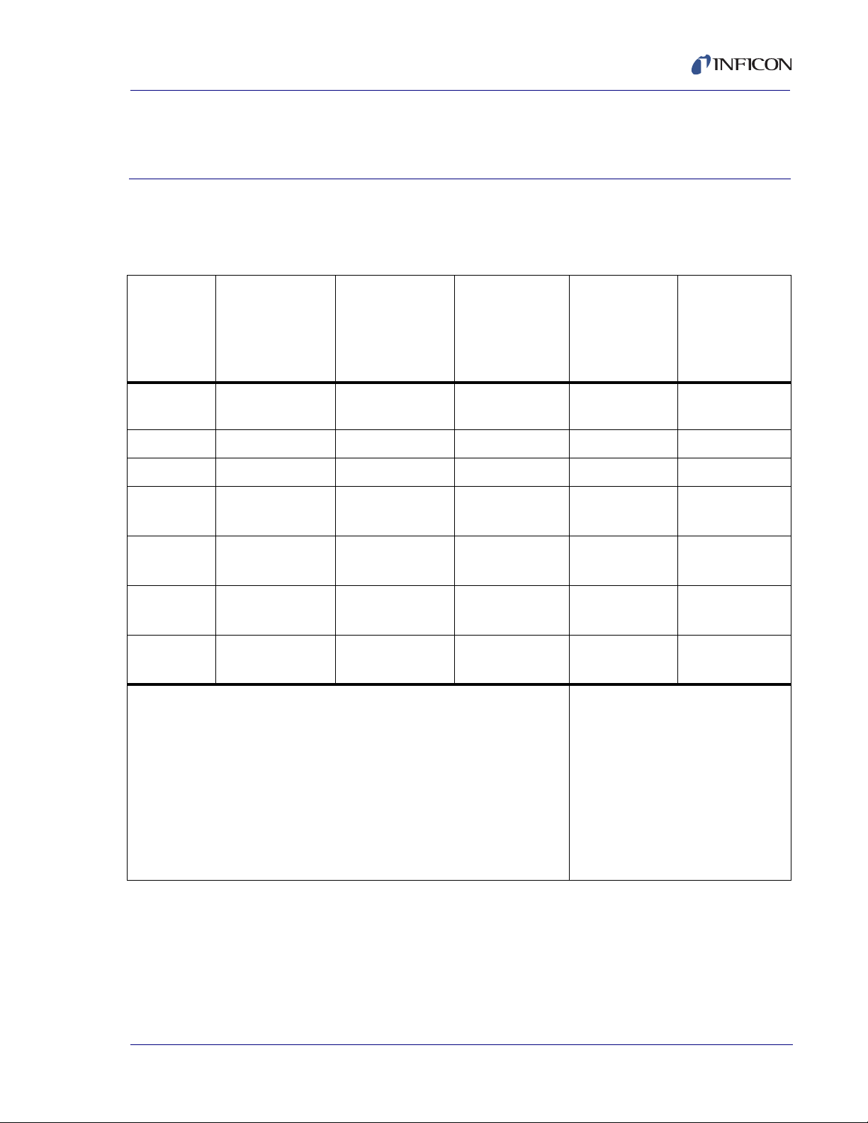
2.1 3000 Micro GC Specifications
Table 2-1 Specifications
3000 Micro GC Operating Manual
Chapter 2
Specifications
1 or 2-channel
3000 Micro GC
Main
voltage
Power 100 VA 130 VA 130 VA 1.2/0.6 A 1.2/0.6 A
Frequency 50-60 Hz 50-60 Hz 50-60 Hz 50-60 Hz 50-60 Hz
Height 15 cm
Width 25 cm
Depth 41 cm
Weight 8.2 kg
* Does not include mounting bracket
PN 074-519-P1C
100-240 V (ac) 100-240 V (ac) 100-240 V (ac) 115/230 V (ac) 115/230 V (ac)
(6 in.)
(10 in.)
(16.5 in.)
(18.0 lb.)
3 or 4-channel
3000 Micro GC
15.5 cm
(6.1 in.)
48 cm
(18.5 in.)
42 cm
(16.5 in.)
11.2 kg
(24.8 lb.)
Portable
3000 Micro GC
15.5 cm
(6.1 in.)
36.4 cm
(14.3 in.)
41.3 cm
(16.3 in.)
16.6 kg
(36.5 lb.)
Heated
Vaporizer
(PN G2819A-X
/ G2846A-X1/
G2857A-X
15 cm
(6 in.)
12.5 cm
(5 in.)
9 cm
(3.5 in.)
1.4 kg
(3.1 lb.)*
1
Where X is the country specific
power cord number:
1
1
)
1: China
2: Europe
3: US
4: Japan
5: UK/HK/SG/MY
6: Australia/NZ
7: Korea
Heated
Regulator
(PN G2818A-X
G2845A-X
G2858A-X
15 cm
(6 in.)
12.5 cm
(5 in.)
9 cm
(3.5 in.)
1.65 kg
(3.64 lb.)*
1
1
1
/
/
)
2 - 1
Page 28

3000 Micro GC Operating Manual
2.2 Environmental Conditions
The following specifications are applicable to the 3000 Micro GC Heated Regulator
and Heated Vaporizer sample conditioners.
Operating temperature range. . . . . . 0 to 50°C
Relative humidity . . . . . . . . . . . . . . . 5 to 95% (non-condensing)
Altitude . . . . . . . . . . . . . . . . . . . . . . . 4572 m (15000 ft.)
Usage location . . . . . . . . . . . . . . . . . Temperature controlled environment
2.3 Instrument Specifications
2.3.1 Sample Inlet Specifications
Sample type . . . . . . . . . . . . . . . . . . . Gas
Maximum sample pressure . . . . . . . <172 kPa (25 PSI)
Recommended sample pressure . . . Ambient to 69 kPa (ambient to 10 PSI)
2.3.2 Sample Injector Specifications
Injector types
Variable volume/timed, heated
Variable volume/large loop, heated
Fixed volume, heated
Backflush to vent, heated
Injection volume
1 to 10 μL for variable volume/timed
1 to 30 μL for variable volume/large loop
1 μL for fixed volume injector and backflush injector with fixed mode
2.3.3 Column Heater Specification
Isothermal Operation . . . . . . . . . . . . Ambient plus 15 to 180°C
2.3.4 TCD Specifications
PN 074-519-P1C
2 - 2
Internal Volume . . . . . . . . . . . . . . . . 240 nL
Detection Limit . . . . . . . . . . . . . . . . . Low ppm to 100%
6
Linear Dynamic Range. . . . . . . . . . . 10
±10%
Page 29

2.3.5 Repeatability
Typical results for Relative Standard Deviation (RSD) at constant temperature and
pressure (for C
3000 Micro GC Operating Manual
to C6 components at % level) are shown below for peak areas.
1
Injector Type
Peak Area Repeatability
Variable volume . . . . . . . . . . . . . . . . <1% RSD
Fixed volume . . . . . . . . . . . . . . . . . . <0.2% RSD
Backflush (timed mode) . . . . . . . . . . <1% RSD
Backflush (fixed mode). . . . . . . . . . . <0.5% RSD
2.3.6 Carrier Gas Specifications
Connection to 3000 Micro GC . . . . . 1/8 in. Swagelok fittings
External source . . . . . . . . . . . . . . . . Helium
Hydrogen
Nitrogen
Argon
Carrier gas purity . . . . . . . . . . . . . . . 99.995 to 99.9995%
Input pressure . . . . . . . . . . . . . . . . . 552 to 566 kPa (80 to 82 PSI)
2.3.7 Portable 3000 Micro GC Carrier Gas Specifications
Onboard cylinder source . . . . . . . . . Helium
Nitrogen
Argon
Onboard cylinder capacity . . . . . . . . 12,410 kPa (1800 PSI)
Onboard cylinder usage . . . . . . . . . . 35-40 hours, application dependent
2.3.8 External Input/Output
PN 074-519-P1C
RJ-45 based LAN
Power supply input connector
Remote start
2.3.9 Portable 3000 Micro GC Onboard Battery
The 3000 Micro GC onboard battery will operate the instrument up to two hours,
depending on the application.
2 - 3
Page 30

3000 Micro GC Operating Manual
2.3.10 Safety and Regulatory Standards
Conforms to the following safety standards:
CSA/National Recognized Test Laboratory (NRTL) UL61010-1
International Electrotechnical Commission (IEC) 61010-1
Canadian Standards Association (CSA) C22.2 No. 61010-1
EuroNorm (EN) 61010-1
Conforms to the following regulations on Electromagnetic Compatibility (EMC) and
Radio Frequency Interface (RFI):
CISPR I1/EN 55011 Group 1 Class A IEC/EN 61326
Declaration of Conformity available
2 - 4
PN 074-519-P1C
Page 31

3000 Micro GC Operating Manual
Chapter 3
Overview
3.1 Overview of 3000 Micro GC Instrument and Accessories
3000 Micro GC is a gas analyzer with applications ranging from fixed gases
(H
, O2, N2, CO, CO2, etc.) to light hydrocarbons (methane, ethane, ethylene,
2
propane, butanes, and pentanes) and volatile organic compounds (methanol,
ethanol, benzene, etc.). 3000 Micro GC contains from 1 to 4 channels that perform
analysis in seconds. For many applications, hydrocarbons between the C
boiling range can be detected at mid-to-high ppm concentrations.
NOTE: When installed in a 3000 Micro GC chassis, a module is referred to as a
channel. When standalone, it is referred to as a module.
®
Samples can be introduced manually by a gas tight syringe, Tedlar
sample cylinder such as a summa canister. Samples can also be interfaced to
3000 Micro GC with appropriate INFICON supplied sample conditioners to
facilitate on-line analysis from bench scale or pilot plant reactors, or directly from a
process line. See Chapter 5, Accessory Installation for information on sample
conditioners.
bag, or a
- C10
6
3000 Micro GC is a ready to use solution combining speed of analysis, simplicity,
and small size. Since 3000 Micro GC is a gas chromatographic instrument, all
principles of GC operation and calibration apply.
3000 Micro GC is used in combination with INFICON EZ IQ chromatography
software for instrument control and chromatography analysis.
PN 074-519-P1C
3 - 1
Page 32

3000 Micro GC Operating Manual
Sample Inlet
RS-232 Port
RJ-45 LAN Port
Power Supply Connector
Ven ts
3.2 3000 Micro GC Chassis
There are three types of 3000 Micro GC chassis that house GC modules:
1,2-Channel Chassis, see section 3.2.1 on page 3-2
3,4-Channel Chassis, see section 3.2.2 on page 3-3
Portable Chassis, see section 3.2.3 on page 3-4
3.2.1 1,2-Channel Chassis
The 1,2-channel chassis can accept one or two channels. The carrier gas and
power for a 1,2-channel system must be supplied externally. See Figure 3-1 and
Figure 3-2.
Figure 3-1 Front panel of the 1,2-channel 3000 Micro GC
Figure 3-2 Rear panel of the 1,2-channel 3000 Micro GC
PN 074-519-P1C
3 - 2
Page 33

3.2.2 3,4-Channel Chassis
Sample Inlet
RS-232 Port
RJ-45 LAN Port
Power Supply Connector
Vents
The 3,4-channel chassis can accept three or four channels. The carrier gas and
power for a 3,4-channel system must be supplied externally. See Figure 3-3 and
Figure 3-4.
Figure 3-3 Front panel of the 3,4-channel 3000 Micro GC
Figure 3-4 Rear panel of the 3,4-channel 3000 Micro GC
3000 Micro GC Operating Manual
PN 074-519-P1C
3 - 3
Page 34

3000 Micro GC Operating Manual
Sample Inlet
Onboard carrier
gas control knob
Vents
Power supply
connector
RS-232 Port
RJ-45 LAN Port
3.2.3 Portable Chassis
Portable 3000 Micro GC is a completely self-contained, miniaturized gas
chromatograph specifically designed for fast, accurate analysis in the field. Each
instrument contains one or two GC channels and an internal carrier gas cylinder.
Rechargeable battery packs and automobile power cable options are available for
alternative power sourcing. See Figure 3-5, Figure 3-6, and Figure 3-7.
Figure 3-5 Front panel of the Portable 3000 Micro GC
Figure 3-6 Rear panel of the Portable 3000 Micro GC
3 - 4
Figure 3-7 Onboard carrier gas cylinder (battery installed underneath)
Portable 3000 Micro GC has an internal, refillable carrier gas tank. When full, it can
support 35 to 40 hours of operation, application dependent.
Portable 3000 Micro GC also contains an optional internal, rechargeable lead-acid
battery pack that supports instrument operation without external power.
PN 074-519-P1C
Page 35

3.3 The 3000 Micro GC Module
Channel
A (1)
Channel
Channel
Channel
B (2)
C (3)
D (4)
3000 Micro GC utilizes a modular GC platform, which can simultaneously analyze
samples from one to four independent 3000 Micro GC channels. Each channel (or
module) is a self-contained GC that performs sample injection, separation, and
detection on a set of target components.
When installed in a 3000 Micro GC chassis, a module is referred to as a channel.
When standalone, it is referred to as a module.
Modules may be referred to as Channel A, B, C, D or 1, 2, 3, 4 from left to right.
See Figure 3-8.
Figure 3-8 Modules installed in a 4-channel 3000 Micro GC
3000 Micro GC Operating Manual
PN 074-519-P1C
3.3.1 Principle of 3000 Micro GC Module Operation
The major functions of the 3000 Micro GC module operation are: injection,
separation, and detection.
1 Injection: Gaseous sample is injected into 3000 Micro GC through the heated
inlet manifold. The manifold regulates the sample temperature and directs it
into the 3000 Micro GC injector flow assembly on a module. The sample is
drawn by vacuum pump through the injector sample loop and is released onto
the column.
3 - 5
Page 36

3000 Micro GC Operating Manual
Sample
Flow
Ref
Flow
E
R
V
V
S
i
vOut
rS
I
E
+
-
Sample
Flow
Ref
Flow
rR
2 Separation: As the sample gas enters the column, its component gases are
separated based on their retention or adsorption property with the column
stationary phase material. The longer the component gas is retained by the
column, the later it will elute from of the column for detection. Components may
be separated based on size, polarity, or boiling point, depending on the column.
3 Detection: After column separation, the sample gas enters the Thermal
Conductivity Detector (TCD). 3000 Micro GC employs a
Microelectromechanical systems (MEMS) TCD which operates on a
Wheatstone bridge circuit. The carrier gas enters the TCD via two pathways,
the reference path and the analytical path. The reference path contains only
carrier gas. The analytical path contains carrier gas and sample gas. The TCD
measures the difference in thermal conductivity between the carrier gas
reference and the sample gas components.
For example, the thermal conductivity of helium carrier gas at 300 K is
157 mW/m K. The thermal conductivity of methane sample gas at 300 K is
34 mW/m K.This difference is picked up by the Wheatstone bridge circuit,
generating signal response to the sample component eluted. See Figure 3-9.
Figure 3-9 Wheatstone bridge circuit
PN 074-519-P1C
3 - 6
Page 37

3.3.2 Injector Flow Assembly
The injector flow assembly (see Figure 3-10) consists of:
MEMS injector chip—micro-machined miniature chip that injects sample into
the GC column
Injector Pilot Solenoid Valve—on/off valve that directs carrier gas to drive
diaphragm valves within the MEMS injector chip
Electronic Pressure Control (EPC) Valve—regulates the column head
pressure
Sample Manifold Plate—provides interface between the EPC valve and the
Injector Pilot Solenoid valve to the MEMS injector
Figure 3-10 Injector flow assembly
3000 Micro GC Operating Manual
PN 074-519-P1C
3 - 7
Page 38

3000 Micro GC Operating Manual
3.3.3 Injectors
Depending on application requirements, 3000 Micro GC supports four different
types of injectors. These MEMS based injector “wafers” contain sample loops
etched into the wafer and micro-diaphragm valves used to direct sample and
carrier gas flow. The sample volume is controlled in EZ IQ by the Inject Time in
milliseconds (ms). The Injector Temperature can be set from 40-100
turned off.
3.3.3.1 Variable Injector (Timed)
The variable injector allows the injection volume to be changed by the user. An
inject time of 0 ms results in no injection.
Valid settings are between 10-100 ms. No significant difference in inject volume is
achieved after 100 ms.
The typical setpoint is 25 ms. Values less than 10 ms may result in repeatability
issues.
The higher the setting, the more sample is injected which results in higher
sensitivity. Actual injection volumes are on the order of a few microliters (µL) of gas.
°C or be
Variable injectors will show the matrix effect as the sample density varies with
compositional changes.
3.3.3.2 Variable Large Volume Injector (Timed)
Similar to the Variable Injector, the Large Volume Injector can be programmed to
inject a large volume. Variable Large Volume Injectors should only be used when
low sensitivity (1-10 ppm) is required. An Inject Time of 0 ms results in no injection.
Valid settings are between 10-400 ms. No significant difference in inject volume is
achieved after 400 ms.
Values less than 10 ms may result in repeatability issues.
PN 074-519-P1C
3 - 8
Page 39

3.3.3.3 Fixed Injector
Fixed Injectors are unique to 3000 Micro GC. Fixed Injectors provide the best
accuracy and precision for 0.2% levels and higher.
Valid settings are between 0-50 ms. An inject time of 0 ms results in no injection.
A typical setpoint is 30 ms. No significant difference in inject volume is achieved
from inject times between 15-50 ms. Values less than 15 ms may result in
repeatability issues.
Actual injection volumes are typically 1-2 µL of gas.
Fixed volume injectors should not be used for trace levels (<200 ppm).
Fixed injectors minimize any matrix effects as sample density varies with
compositional changes.
3000 Micro GC Operating Manual
PN 074-519-P1C
3 - 9
Page 40

3000 Micro GC Operating Manual
3.3.3.4 Backflush Injector
The backflush assembly consists of:
a backflush injector
a precolumn
an analytical capillary column
The precolumn is a short section of column, whereas the analytical column is
usually longer. The precolumn and analytical column are connected in series.
The precolumn functions to prevent contaminants from entering the analytical
column. The sample first travels through the precolumn and then through the
analytical column. After components of interest enter the analytical column, the
flow is reversed through the precolumn, flushing the unwanted components to vent.
This backflushing of the precolumn prevents these contaminants from entering the
analytical column and causing deactivation or ghost peaks.
The backflush injector has two method parameters in EZ IQ software: Backflush
Time (in seconds) and Inject Time (in milliseconds). The Backflush Time
parameter on the Instrument Setup window can be changed to suit analysis
needs. Valid settings for the Backflush Time are between 0-240 s. Recommended
settings for the Backflush Time are between 6-12 s. Valid settings for the Inject
Time are between 0-250 ms.
The backflush injector can also function in a semi-fixed mode. An Inject Time of
0 ms results in a fixed volume injected and is best used for component levels from
0.1% and higher. This will result in higher precision.
The backflush injector can function in a variable volume mode. An Inject Time
greater than 10 ms will result in a higher injection volume. This used for component
levels below 0.1%.
Actual inject volumes are typically a few microliters of gas. For better sensitivity, set
a higher Inject Time, however, accuracy and precision will be negatively impacted.
Backflush times vary with column and setpoints and must be optimized for every
3000 Micro GC module.
PN 074-519-P1C
3 - 10
Page 41

3.3.4 Columns
Porous Layer Open Tube
(PLOT)
Wall Coated Open Tube
(WCOT)
Open (Capillary)
3000 Micro GC utilizes capillary columns for separation. Two types of capillary
columns are used: Porous Layer Open Tubular (PLOT) and Wall Coated Open
Tubular (WCOT). The capillary columns are wound into a column can, which is
installed into a module and can be heated up to 180°C. Columns are connected to
the injector on one end and the TCD on the other end using small dead-volume
fittings. Typical column flow rates range from 0.4 to 4 mL/min (cc/min) depending
on column dimensions.
PLOT columns have small particles embedded on the surface of the column. See
Figure 3-11. PLOT column separation is based on gas-solid partitioning. The most
popular PLOT columns are Molecular Sieve 5A (MolSieve), PLOT Q, PLOT U and
Alumina. PLOT columns separate according to compound polarity. Typical lengths
are 4 to 30 m with an internal diameter of 0.32 mm.
WCOT columns have a chemical stationary phase bonded to the internal surface
of the column. (See Figure 3-11.) WCOT separation based on gas-liquid
partitioning. OV-1 is a commonly used WCOT column, which separates
compounds according to boiling point. Typical lengths are 4 to 14 m, with an
internal diameter of 0.15 mm. Stationary phase thicknesses of 1.2 or 2 µm are used
for the OV-1. Other columns are also used in 3000 Micro GC, such as Stabilwax
OV-1701, etc.
3000 Micro GC Operating Manual
®
,
Figure 3-11 PLOT and WCOT columns
PN 074-519-P1C
Separation may be optimized by varying the column coating type and thickness,
column length and diameter, and carrier gas type. EZ IQ can further optimize
separation by adjusting column head pressure and column temperature.
3 - 11
Page 42

3.3.5 Detector
3000 Micro GC uses a MEMS based TCD, which has a 240 nL internal cell volume.
(See Figure 3-12.) The small volume provides for excellent sensitivity. For some
components, a detection limit of 1 ppm can be achieved.
NOTE: TCD sensitivity is matrix, carrier gas, and component dependent.
The TCD uses a Wheatstone bridge design and has a sample and reference
channel. The TCD detects the difference in thermal conductivity of the gas traveling
through the reference side (pure carrier gas) versus the gas traveling through the
sample side (carrier gas plus the sample gas). When ON, the TCD filament is hot.
3000 Micro GC monitors the column pressure. If carrier gas flow is turned off, the
TCD will automatically turn off.
Figure 3-12 MEMS TCD detector
3000 Micro GC Operating Manual
3.3.6 D-Board
A Detector board, also known as a D-board, is attached to the side of each module.
The D-Board controls the module conditions and communicates module
information and setpoints to the Communications Board (C-Board, see section
3.4.2 on page 3-15). 3000 Micro GC supports two types of D-board: Enhanced and
Standard.
3.3.6.1 Enhanced D-Board
Enhanced D-Board circuitry significantly reduces solvent peak tailing, resulting in
better chromatography and improved sensitivity of peaks eluting after the solvent
peak (e.g., air). This feature is most useful for applications that involve low ppm
trace analysis in a solvent gas.
3.3.6.2 Standard D-Board
The Standard D-Board circuitry is for general purpose applications with a
mid-to-high ppm analysis requirement.
PN 074-519-P1C
3 - 12
Page 43

3.3.7 Module Cases
3000 Micro GC supports two types of module cases, a standard module case and
a Modbox module case.
3.3.7.1 Standard Module Case
The standard module case is used for most column types. MolSieve modules are
an exception. See Figure 3-13.
Figure 3-13 Standard module
3000 Micro GC Operating Manual
3.3.7.2 Modbox Module Case
The Modbox module allows the column to be wound in a larger diameter. The
MolSieve column benefits from this design because the column is vulnerable to
breakage when winding into a small diameter. See Figure 3-14.
Figure 3-14 Modbox module
PN 074-519-P1C
3 - 13
Page 44

3000 Micro GC Operating Manual
To c olum n
To column
Sample inlet
Sample inlet
3.4 3000 Micro GC Chassis Components
3000 Micro GC modules are installed into the 3000 Micro GC chassis. The
components that are integrated into the chassis are:
Inlet Tubing, see section 3.4.1 on page 3-14
C-Board, see section 3.4.2 on page 3-15
OBC Board, see section 3.4.3 on page 3-15
Sample Pump, see section 3.4.4 on page 3-16
Carrier Gas Weldment, see section 3.4.5 on page 3-17
Carrier Gas Inlet, see section 3.4.6 on page 3-18
Vents, see section 3.4.7 on page 3-19
Remote Control Module, see section 3.4.8 on page 3-20
3.4.1 Inlet Tubing
The inlet tubing is enclosed in a heated compartment which contains a short piece
of 1/16 in. OD tubing. One side of the tubing is connected to the sample fitting on
the front panel. The other side of the tubing connects to one or more modules.
Depending on instrument configuration, the tubing is split to each module.
Temperatures can be set from 45-140
The inlet temperature can also be turned off. The internal surface of the tubing is
deactivated to ensure the surfaces of the tubing are inert.
°C. Typical setpoints are between 80-100°C.
Figure 3-15 Inlet tubing of a 2-Channel 3000 Micro GC with two inlets
PN 074-519-P1C
3 - 14
Page 45

3.4.2 C-Board
The Communications Board, also known as the C-board is internally mounted on
the side of 3000 Micro GC. It controls the inlet zone heater and communicates with
the D-boards and onboard computer.
3.4.3 OBC Board
The onboard computer (OBC) is internally mounted on the back of 3000 Micro GC.
It is the main processor which communicates with the C-board and the external
control system. OBC has an internal flash memory which stores 3000 Micro GC
configuration information. See Figure 3-16.
Figure 3-16 Onboard computer (OBC)
3000 Micro GC Operating Manual
The OBC provides a RJ-45 based LAN interface. 3000 Micro GC can be connected
to a LAN network or directly to an external control system (i.e., EZ IQ software) via
a RJ-45 LAN connection.
Figure 3-17 LAN connection on rear side of 3000 Micro GC
PN 074-519-P1C
3 - 15
Page 46

3000 Micro GC Operating Manual
3.4.4 Sample Pump
One or two sample pumps are installed internally in 3000 Micro GC. There is no
flow through the sample path until the pump turns on. When the sample pump turns
on, the sample is drawn through the sample inlet tubing and the sample injectors
open for the time specified in the acquisition method. Set pump time at a minimum
of 20 seconds. If sufficient sample gas is available, increase the pump time to 60
seconds. The sample pump draws at a rate of 10 mL/min.
NOTE: For specific applications, there is a mode of operation called continuous
where the pumps can be turned off and sample gas flows continuously
through the internal tubing. Continuous operation can only be used with
variable and fixed volume injectors.
Backflush injectors cannot be used in continuous mode. In continuous
mode, the sample valve always remains on (open) and sample gas can
flush the sample inlet lines and injector.
Figure 3-18 Sample pump
3 - 16
PN 074-519-P1C
Page 47

3.4.5 Carrier Gas Weldment
Base plate
The carrier gas weldment connects the carrier gas to each module. It consists of a
base plate and stainless steel tubing. Base plates align to each module.
NOTE: See section 8.2, Remove and Replace a 3000 Micro GC Module, on page
8-5 for more information about how to align a module.
Figure 3-19 Carrier gas weldment
3000 Micro GC Operating Manual
PN 074-519-P1C
3 - 17
Page 48

3000 Micro GC Operating Manual
3.4.6 Carrier Gas Inlet
One or two carrier gases can be configured with the carrier gas inlets located on
the rear of 3000 Micro GC. See Figure 3-20, Figure 3-21, and Figure 3-22.
Figure 3-20 Carrier Gas inlet of a 1,2-Channel 3000 Micro GC
Figure 3-21 Carrier Gas inlet of a 3,4-Channel 3000 Micro GC
3 - 18
Figure 3-22 Carrier gas inlet of a Portable 3000 Micro GC
PN 074-519-P1C
Page 49

3.4.7 Vents
3000 Micro GC Operating Manual
Analytical vents expel sample gas and carrier gas mixture from the sample side
of the TCD. Reference vents expel carrier gas from the reference side of the TCD.
Sample vents expel sample gas when the sample pump is drawing sample gas into
sample loop or the sample is backflushed from pre-column out of 3000 Micro GC.
See Figure 3-23, Figure 3-24 and Figure 3-25.
Figure 3-23 Vent outlets for a 1,2-Channel 3000 Micro GC
Figure 3-24 Vent outlets for a 3,4-Channel 3000 Micro GC
Figure 3-25 Vent outlets for a Portable 3000 Micro GC
PN 074-519-P1C
3 - 19
Page 50

3000 Micro GC Operating Manual
3.4.8 Remote Control Module
The Remote Control Module allows an external control system to start
3000 Micro GC. The Remote Control Module port is located on the rear of
3000 Micro GC. See Figure 3-26.
Figure 3-26 Remote connector on the rear panel.
3 - 20
PN 074-519-P1C
Page 51

3.5 Sample Conditioners
CAUTION
3000 Micro GC is a gas-only analyzer!
Extreme caution must be taken to ensure that liquid and
solid particles are not introduced into 3000 Micro GC.
A 10 micron sample inlet filter (PN G2801-60900) is provided in the 3000 Micro GC
ship kit and must be connected to instrument sample inlet at installation. In
addition, a variety of sample conditioners are available to ensure sample entering
the instrument is in gas phase and that the sample gas pressure is below 25 PSI.
Available sample conditioners:
Genie Filter Assembly
Pressure Reducer
3000 Micro GC Operating Manual
Pressure Reducer and Genie Filter Assembly
Heated Regulator
Heated Vaporizer for Liquefied Petroleum Gas (LPG)
For more detailed description of each sample conditioner, see section 5.1, Sample
Conditioners, on page 5-1.
PN 074-519-P1C
3 - 21
Page 52

3000 Micro GC Operating Manual
3.6 EZ IQ Chromatography Software
EZ IQ is a powerful chromatography software running under the
Microsoft Windows
interface. EZ IQ supports three languages: English, Chinese, and Japanese. See
Figure 3-27.
Figure 3-27 EZ IQ software interface
®
operating system with an easy-to-use graphical user
3 - 22
PN 074-519-P1C
Page 53

3.7 Product Identification
Each 3000 Micro GC carries a configuration specific part number (PN:), serial
number (SN:) and identification number (ID:). When contacting INFICON regarding
a 3000 Micro GC, please have all three product identification numbers available.
See Figure 3-28.
Figure 3-28 3000 Micro GC product label.
3000 Micro GC Operating Manual
PN 074-519-P1C
3 - 23
Page 54

3000 Micro GC Operating Manual
3.7.1 1,2-Channel and Portable 3000 Micro GC Part Numbering
The 1,2-channel 3000 Micro GC chassis and the Portable 3000 Micro GC chassis
can be equipped with one or two channels (modules). Figure 3-29 shows how an
instrument part number is constructed for both types of chassis.
Figure 3-29 1,2-Channel and Portable 3000 Micro GC part number format
GC Prefix: a fixed two digit prefix and is same for every instrument
Chassis Type: a two digit number representing the chassis type, including
sample inlet, carrier gas and number of channels
Power Cord: a one digit number representing the country specific power cord
Number for Channel A: a two digit number that specifies a particular channel
equipped with an application specific injector type, column type, and length
Number for Channel B: a two digit number that specifies a particular channel
equipped with an application specific injector type, column type, and length
NOTE: At least one channel must be specified for each 1,2-channel or
Portable 3000 Micro GC. The number for Channel B is only specified when
Channel B is present.
PN 074-519-P1C
3 - 24
Page 55

3000 Micro GC Operating Manual
3.7.2 3,4-Channel 3000 Micro GC Part Numbering
The 3,4-channel 3000 Micro GC chassis can be equipped with three or four
channels (modules). Figure 3-30 shows how an instrument part number is
constructed for a 3,4-channel chassis.
Figure 3-30 3,4-Channel 3000 Micro GC part number format
GC Prefix: a fixed two digit prefix and is same for every instrument
Chassis Type: a two digit number representing the chassis type, including
sample inlet, carrier gas, and number of channels
Power Cord: a one digit number representing the country specific power cord
Number for Channel A: a two digit number that specifies a particular channel
equipped with an application specific injector type, column type, and length
Number for Channel B: a two digit number that specifies a particular channel
equipped with an application specific injector type, column type, and length
Number for Channel C: a two digit number that specifies a particular channel
equipped with an application specific injector type, column type, and length
PN 074-519-P1C
Number for Channel D: a two digit number that specifies a particular channel
equipped with an application specific injector type, column type, and length
NOTE: At least three channels must specified for a 3,4-channel 3000 Micro GC.
The number for Channel D is only specified when Channel D is present.
See Figure 3-31 on page 3-26 for an example of a 3000 Micro GC product label.
3.7.3 Serial Number
Each serial number (SN:) uniquely identifies an instrument. This number is stored
in the manufacturing database for traceability.
3 - 25
Page 56

3000 Micro GC Operating Manual
3.7.4 Identification Number
Each instrument is uniquely identified by an identification number (ID:).
See Figure 3-31.
Figure 3-31 3000 Micro GC identification number format
CN Prefix: a fixed two digit prefix and is the same for every instrument
Hardware Identification
0 indicates the module is equipped with Standard D-board
1 indicates the hardware is an instrument
2 indicates the module is equipped with Enhanced D-board
Manufacturing Year: a two digit year
For instance, 2014 is represented as 14
Manufacturing Week Number: is a two digit week number
For instance, the first week in January is represented as 01
Incremental Number: is based on Manufacturing Week and is a three digit
number
For instance, the first instrument manufactured in a week is
represented as 001.
PN 074-519-P1C
3 - 26
Page 57

4.1 Site Preparation
Before installation, make sure that the installation site is fully prepared. Contact
INFICON with any question regarding site preparation.
4.1.1 List of Required Tools
Adjustable wrench (small)
Adjustable wrench (large)
Two 7/16 in. open-ended wrenches
9/16 in. open-ended wrench
5/16 in. open-ended wrench
3000 Micro GC Operating Manual
Chapter 4
Installation
1/4 in. open-ended wrench
Tubing cutter
®
Te flo n
tape
4.1.2 Tubing and Fitting Requirements
Use pre-cleaned copper or stainless steel tubing, 1/8 in. OD, for carrier gas
connections between the tank regulator and 3000 Micro GC.
3000 Micro GC has a 1/8 in. Swagelok male carrier gas connection.
Pre-cleaned, GC grade copper tubing in 50 ft. lengths can be purchased
from various chromatography vendors. It is also included in the optional
PN 074-519-P1C
Swagelok 1/8 in. nuts, front ferrules, and back ferrules.
Install Kit for Micro GC (PN G2860A).
Do not clean the tubing with a solvent prior to use.
®
Do not use Teflon or Tygon
tubing for the carrier gas.
4 - 1
Page 58

3000 Micro GC Operating Manual
4.1.3 Site Requirements
4.1.3.1 Electrical Requirements
A standard 100 to 240 V(ac) electrical outlet is required. A
Universal/Uninterruptable Power Supply (UPS) or surge protector is
recommended.
4.1.3.2 Space and Venting Requirements
For optimum 3000 Micro GC performance and lifetime, allow unrestricted airflow
around 3000 Micro GC to dissipate heat.
Safely vent sample streams—potentially toxic, noxious, or flammable
gases—outside the instrument and away from the operating area. Vent toxic gases
to a hood, chemical trap, or reaction medium.
Avoid venting the instrument into drafty areas, such as in front of a heating/cooling
vent.
4.1.4 computer Requirements
Microsoft Operating Systems
Windows XP Pro with Service Pack 3 or Windows 7
.Net 3.0 or 3.5 Service Pack 1
Dual Core 2 Ghz CPU, 2 GB RAM, >10 GB free space
DVD Drive
Network card for Ethernet connection to 3000 Micro GC (TCP/IP)
PN 074-519-P1C
4 - 2
Page 59

3000 Micro GC Operating Manual
CAUTION
CAUTION
CAUTION
4.1.5 Gas and Regulator Requirements
4.1.5.1 Carrier Gas and Regulator Requirements
A continuous, controlled flow of carrier gas is required.
Use high purity grade gas specifically intended for chromatographic use. All carrier
gas types should be 99.995% to 99.9995% pure.
The carrier gas tank requires a dual stage regulator capable of delivering
80 to 82 PSI of gas pressure. The regulator outlet fitting must be adapted to
Swagelok in order to connect the tubing. Use 1/8 in. fittings or 1/8 in. adapters.
Exceeding 82 PSI for the carrier gas pressure may result
in instrument damage.
To protect 3000 Micro GC and to enhance performance,
carrier gas traps must be used to purify the carrier gas
before the carrier gas is introduced into 3000 Micro GC.
A hydrocarbon/moisture trap (PN G2870A-01) is usually
sufficient.
4.1.5.2 Calibration Gas and Regulator Requirements
Obtain an ample supply of a calibration gas, specific to the analysis needs, from a
commercial vendor.
For the most accurate measurements, use a calibration gas that closely resembles
the actual sample gas composition.
PN 074-519-P1C
A regulator specific to the calibration gas cylinder should be used. The regulator
should be capable of supplying output pressure from ambient to 25 PSI. The
regulator must be clean, grease free and non-venting.
Checkout gas mixtures supplied by INFICON are not
calibration gases. Checkout gas mixtures are only used
for instrument installation and start up.
4 - 3
Page 60

3000 Micro GC Operating Manual
4.2 Instrument Hardware Setup
4.2.1 Unpacking the Instrument
Verify the contents of the order, including software, sample conditioners, and
checkout gases, against the packing list. The contents of the shipping kit should
also be verified.
4.2.2 Shipping Kit Contents
A PN 074-542-P1 3000 Micro GC Shipping Kit Packing List is included with each
instrument package. This packing list will indicate which items are included for a
particular instrument configuration.
4.2.2.1 Shipped with Every Instrument
PN
Description Quantity
5183-0394 . . . . . 1/16 and 1/8 in. Nut and Ferrule Set, 2 pack . . . . . 1 pc
5183-4649 . . . . . Crossover Ethertwist Cable, 10 ft. . . . . . . . . . . . . . 1 pc
5183-4652 . . . . . 3000 Micro GC Replacement Filters, 5 Pack . . . . . 1 pc
G2890-90701 . . . Carrier Gas Label Ar/N
G2890-90702 . . . Carrier Gas Label He/N
. . . . . . . . . . . . . . . . . . . . . 2 pc
2
. . . . . . . . . . . . . . . . . . . . . 2 pc
2
0100-2375 . . . . . Male Luer x 1/16 in. ID Tube Bar . . . . . . . . . . . . . . 5 pc
0890-2183 . . . . . Tubing, 0.066 in. ID Polyurethane . . . . . . . . . . . . 100 cm
0100-2378 . . . . . Female Luer x 1/6 in. ID Tube Barb Panel . . . . . . . 5 pc
G2801-90200 . . . 3000 Micro GC Factory Info CD . . . . . . . . . . . . . . . 1 pc
G2801-90118 . . . 3000 Micro GC User Information CD . . . . . . . . . . . 1 pc
G2801-90108 . . . 3000 Micro GC Installation Poster . . . . . . . . . . . . . 1 pc
PN 074-519-P1C
4 - 4
Page 61

3000 Micro GC Operating Manual
4.2.2.2 Configuration Dependent Parts
4.2.2.2.1 1,2-Channel and 3,4-Channel 3000 Micro GC Specific Parts
PN
Description Quantity
G2801-60747 . . . 24 V (dc) AC/DC Power Supply . . . . . . . . . . . 1 pc
4.2.2.2.2 Portable 3000 Micro GC Specific Parts
PN
Description Quantity
PNU-2058. . . . . . Onboard Carrier Gas Refiller Apparatus. . . . . 1 pc
G2801-60748 . . . 15 V (dc) AC/DC Power Supply . . . . . . . . . . . 1 pc
4.2.2.2.3 Sample Inlet Parts
PN
Description # of Inlets Quantity
G2801-60900 . . . Sample Inlet Filter, stainless steel. . . . . . 1 or 2 . . . . 1 or 2 pc
5185-5817. . . . . . . Gas Sampling Tubing 1/16 in. SS with Fittings . .1 or 2 . . . . 1 or 2 pc
FRL-1269 . . . . . . Ferrule Dual End . . . . . . . . . . . . . . . . . . . 1 or 2 . . . . 1 or 2 pc
4.2.2.2.4 Gas Inlet Parts
PN
Description # of Carriers Quantity
3150-0602 . . . . . Carrier gas filter, CO2 Cryo . . . . . . . . . . .1 or 2 . . . . 1 or 2 pc
4.2.2.2.5 GC Module Parts
PN
Description # of GC Modules Quantity
G2801-00952 . . . Gang Block Keepers . . . . . . . . . . . . . . . . 1 to 4 . . . . 1 to 4 pc
4.2.2.2.6 Power Cords - Country Dependent
PN
Description Quantity
8121-0723 . . . . . Power Cord, China . . . . . . . . . . . . . . . . . . . 0 or 1 pc
PN 074-519-P1C
8120-1689 . . . . . Power Cord, Europe . . . . . . . . . . . . . . . . . . 0 or 1 pc
8120-1378 . . . . . Power Cord, US . . . . . . . . . . . . . . . . . . . . . 0 or 1 pc
8120-4753 . . . . . Power Cord, Japan . . . . . . . . . . . . . . . . . . . 0 or 1 pc
8120-8705 . . . . . Power Cord, GB/HK/SG/MY . . . . . . . . . . . . 0 or 1 pc
8120-1369 . . . . . Power Cord, Australia/NZ . . . . . . . . . . . . . . 0 or 1 pc
8121-1226 . . . . . Power Cord, Korea . . . . . . . . . . . . . . . . . . . 0 or 1 pc
4 - 5
Page 62

3000 Micro GC Operating Manual
Female fitting (1/8 in.)
Front ferrule (1/8 in.)
Back ferrule (1/8 in.)
Swagelok nut (1/8 in.)
Tubing (1/8 in.)
4.2.3 Making Carrier Gas and Sample Inlet Connectors
3000 Micro GC is equipped with a 1/8 in. carrier gas Swagelok connector on the
back of the instrument. This section demonstrates how to assemble 1/8 in. carrier
gas tubing with the instrument.
The following procedure reviews how to make Swagelok connections. This
procedure explains how to connect tubing to a fitting, such as the sample inlet(s),
carrier gas inlet(s), or the gas supply tank.
Materials Needed
1/8 in. OD pre-cleaned copper or stainless steel tubing
1/8 in. Swagelok nuts, and front and back ferrules
Two 7/16 in. wrenches for 1/8 in. tubing
Two 5/16 in. wrenches for 1/16 in. tubing
Procedure
1 Attach a 1/8 in. Swagelok nut, back ferrule and front ferrule to the tubing as
shown in Figure 4-1.
Figure 4-1 Swagelok nut and ferrules setup on tubing
2 Clamp a female fitting in a bench vise.
3 Push the tubing into the female fitting.
PN 074-519-P1C
4 - 6
Page 63

3000 Micro GC Operating Manual
Female fitting
in vise
Front ferrule, back ferrule, and nut
Pencil line
4 Ensure that the front ferrule makes contact with the female fitting, slide the
Swagelok nut over the ferrule, then finger tighten. See Figure 4-2.
Figure 4-2 Vise fitting assembly
5 Push the tube fully into the female fitting.
6 Mark the Swagelok fitting with a pencil line as shown in Figure 4-3.
Figure 4-3 Pencil line
7 Tighten the 1/8 in. fitting 3/4 of a turn, referenced to the pencil line, using one
7/16 in. wrench to hold the fitting steady, and the other 7/16 in. wrench to turn
the fitting. See Figure 4-4.
Figure 4-4 Using wrenches to tighten Swagelok fittings
PN 074-519-P1C
8 Unscrew the nut. Connect the tubing with the swaged ferrules to the pencil
marked location. Tighten the nut 1/4 turn past finger tight.
3000 Micro GC is equipped with a 1/16 in. sample inlet Swagelok connector on the
faceplate. Connecting sample inlet tubing is the same procedure as described for
carrier gas inlet tubing.
4 - 7
Page 64

3000 Micro GC Operating Manual
WARNING
WARNING
WARNING
4.2.4 Connecting the Carrier Gas
4.2.4.1 Gas Safety
Gas cylinders present a hazard when not secured
properly. Securely fasten all compressed gas cylinders to
an immovable structure or permanent wall. Store and
handle compressed gases in accordance with safety
procedures.
Gas cylinders may present a hazard under extreme
temperature conditions. Do not store gas cylinders in the
path of heated oven exhausts or other sources of heat.
Do not expose cylinders to extreme cold or heat. It is
recommended to store or place cylinders in a
temperature controlled environment.
Wear eye protection when using compressed gas.
PN 074-519-P1C
4 - 8
Page 65

3000 Micro GC Operating Manual
Particulate Filter
(3150-0602)
Arrow points to
3000 Micro GC
Cutoff valve (not provided)
15 cm (6 in.)
4.2.4.2 Connecting the Carrier Gas Particulate Filter
1 Remove any shipping caps on 3000 Micro GC.
2 Install one carrier gas particulate filter (PN 3150-0602) on the carrier gas
supply tubing for each carrier gas used (see Figure 4-5). Do not connect the
tubing to 3000 Micro GC at this time.
Figure 4-5 Carrier gas particulate filter setup
Install the carrier gas filter within 15 cm (6 in.) of the 3000 Micro GC fitting
to maximize its effectiveness.
Use a cutoff valve (not provided) as shown in Figure 4-5 for ease of
maintenance. The valve should be "packless" (sealed to atmosphere) and
grease free. Common industrial or home-supply ball valves should not be
used.
Chemical traps on the carrier gas line may be used to protect the column.
PN 074-519-P1C
4 - 9
Page 66

3000 Micro GC Operating Manual
WARNING
CAUTION
CAUTION
4.2.4.3 Setting the Gas Pressure
Set the carrier gas regulator as shown in Table 4-1.
Table 4-1 Carrier gas input pressure
Carrier Gas Required Delivery Pressure
helium*
hydrogen*
argon
nitrogen
* Required for checkout
Never fill the Portable 3000 Micro GC internal gas
cylinder with hydrogen. A hydrogen leak inside the
instrument can present an explosion hazard.
Exceeding 82 PSI for the carrier gas pressure may result
in damage to 3000 Micro GC.
552 +/- 14 kPa (80 +/- 2 PSI)
552 +/- 14 kPa (80 +/- 2 PSI)
552 +/- 14 kPa (80 +/- 2 PSI)
552 +/- 14 kPa (80 +/- 2 PSI)
Carrier gas pressure below 78 PSI will negatively affect
3000 Micro GC operation.
4.2.4.4 Purge the Carrier Gas Line
Ensure the gas line is not connected to the instrument. Purge carrier gas supply
lines to remove air by opening the tank and letting the carrier gas flow for
five to ten seconds.
4 - 10
PN 074-519-P1C
Page 67

3000 Micro GC Operating Manual
WARNING
CAUTION
4.2.4.5 Connecting the Carrier Gas to the 3000 Micro GC
1 Connect the carrier gases to the instrument via the 1/8 in. Swagelok fitting(s)
located on the back of the instrument. See section 4.2.3 on page 4-6.
If a hazardous sample is used, the sample exhaust must
be vented to a fume hood or other designated area for
hazardous waste disposal.
Do not use leak detection fluids.
4.2.4.6 Using the Onboard Carrier Gas Cylinder (Portable 3000 Micro GC only)
For information on refilling the internal carrier gas cylinder, see section 8.5.3.1,
Refill Onboard Carrier Gas Cylinder, on page 8-43.
1 Remove the shipping caps.
2 Ensure the carrier gas knob on the front of the instrument is set to OFF.
See Figure 4-6.
Figure 4-6 Carrier gas knob
PN 074-519-P1C
3 Connect the CARRIER OUT port to the CARRIER IN port with the carrier
jumper tube as show in Figure 4-7. Use CARRIER IN port 1 if 3000 Micro GC
has two ports available.
4 - 11
Page 68

3000 Micro GC Operating Manual
WARNING
Analytical column vents
Reference column vents
Sample pump vents
CARRIER OUT port
Carrier jumper tube
CARRIER IN ports
for onboard cylinder
Figure 4-7 Portable 3000 Micro GC, back view
4.2.5 Installing the Sample Inlet Filter
4.2.5.1 Sample Inlet Filter Parts List
4 Set the carrier switch on the front of Portable 3000 Micro GC to ON.
5 Connect sample gases.
If a hazardous sample is used, the sample exhaust must
be vented to a fume hood or other designated area for
hazardous waste disposal.
3000 Micro GC is shipped with an external 10 micron sample inlet filter assembly,
one dual-ended ferrule per sample inlet, and extra replacement filter disks.
Table 4-2 Sample inlet filter parts list
Description PN
Sample Inlet Filter Assembly G2801-60900
PN 074-519-P1C
4 - 12
Dual-Ended Ferrule FRL-1269
Replacement Filter Disks (5/pk) 5183-4652
Page 69

4.2.5.2 Tools Required
CAUTION
Part B
Part A
Filter disk
Dual-ended ferrule
To GC
Two 7/16 in. wrenches, for the sample inlet filter assembly
One 5/16 in. wrench, for user sample line to sample inlet filter
4.2.5.3 Sample Inlet Filter Assembly Installation
1 Shut off any sample flow to 3000 Micro GC.
2 Allow the sample inlet to cool.
3 Disconnect the sample line to the 3000 Micro GC input fitting using the 5/16 in.
wrench, while holding the sample inlet filter with a 7/16 in. wrench.
4 Inspect the sample inlet filter assembly and verify that the filter disk is in place.
If not, place a filter disk between parts A and B of the filter body and thread the
parts together until finger-tight. See Figure 4-8.
Figure 4-8 Exploded view of sample inlet filter assembly G2801-60900
3000 Micro GC Operating Manual
5 Install the sample inlet filter assembly on the 3000 Micro GC inlet using the
dual-ended ferrule. Use the two 7/16 in. wrenches to tighten the filter halves
until snug.
5a Tighten sample inlet filter assembly to 3000 Micro GC inlet an additional
1/4 turn using 7/16 in. wrench on filter Part A.
6 Connect the sample line to the male portion of filter Part B, shown in Figure 4-8,
while stabilizing the sample inlet filter assembly Part B using a 7/16 in. wrench.
PN 074-519-P1C
Do not overtighten the sample inlet filter assembly to
3000 Micro GC. This will damage the dual-ended ferrule.
4 - 13
Page 70

3000 Micro GC Operating Manual
Crossover cable
(PN 5183-4649)
Standalone Installation
Power cord and converter
Remote start/stop
cable (PN G2801-60618)
Crossover cable
(PN 5183-4649)
4.2.6 Power and Communication Cable Setup
1 Connect the crossover cable (PN 5183-4649) between the computer and
3000 Micro GC.
NOTE: If a LAN connection through a hub is required, consult an IT specialist
to configure the setup.
2 Connect the power cable to the AC/DC converter supplied in the Shipping Kit.
3 If desired, connect the remote start cable (PN G2801-60618) to
3000 Micro GC. See section 5.2, The Remote Connector, on page 5-30 for
remote start cable pinout details.
4 If a customized checkout is necessary or no checkout is required, reconfigure
carrier gas type as needed by following the instructions in section 6.4, Change
Carrier Gas Configuration, on page 6-9.
Figure 4-9 Power and communication connections
4 - 14
PN 074-519-P1C
Page 71

3000 Micro GC Operating Manual
Channel B inlet
Channel A inlet
On/off switch
4.3 Instrument Configuration Setup
3000 Micro GC can be connected directly to the computer on a LAN using a
crossover cable (PN 5183-4649, supplied in the Shipping Kit). Use a crossover
cable to establish the initial connection.
4.3.1 Turn on 3000 Micro GC
To turn on 3000 Micro GC, set the switch on the front of the instrument to the on
position. The switch will illuminate green to indicate that 3000 Micro GC is on.
Figure 4-10 INFICON 3000 Micro GC (2-channel, two inlet instrument shown)
PN 074-519-P1C
4 - 15
Page 72

3000 Micro GC Operating Manual
4.3.2 IP Address Configuration
The IP address on the computer must be changed in order to communicate with
3000 Micro GC. Set the IP address as follows, assuming the computer is running
Windows XP operation system:
1 Click Start >> Connect To >> Show All Connections.
2 Click Local Area Connection on the Network Connections window.
3 Click the General tab and click Properties.
4 Highlight Internet Protocol (TCP/IP) and click Properties.
NOTE: If 3000 Micro GC will be set up on a LAN, record all of the computer’s
current IP address settings. It is recommended that an IT specialist be
consulted when any IP addresses are configured on a LAN.
5 Click Use the following IP address.
6 For a direct connection via the crossover cable, the IP address must be set to
10.1.1.100. The subnet mask must be set to 255.255.255.0. The Default
gateway and DNS server can remain blank for a direct connection. See Figure
4-11.
Figure 4-11 IP address TCP/IP
PN 074-519-P1C
4 - 16
7 Click OK in the Internet Protocol (TCP/IP) Properties window and
subsequent window to make the entered IP address effective.
Page 73

4.3.3 Ping the Instrument
Ensure that the instrument is turned on and is fully booted up. On the computer,
click Start >> Run and type ping 10.1.1.101. Ensure data packets are being
received, as shown in Figure 4-12. If data packets are not being received, check
the IP settings or consult the troubleshooting table in section 9.1.3, Common
Connection Problems, on page 9-8.
NOTE: At the factory, the instrument IP address was set to 10.1.1.101.
Figure 4-12 Command prompt showing successful ping
3000 Micro GC Operating Manual
4.3.4 Carrier Gas Configuration
At the factory, 3000 Micro GC is configured to use helium carrier gas to verify
instrument quality. If the checkout gas was ordered from INFICON and it will be
used for the instrument checkout, do not change the carrier gas software setup at
PN 074-519-P1C
this point.
If a customized checkout gas is necessary or no checkout is required, reconfigure
the carrier gas type as needed by following the instructions in section 6.4, Change
Carrier Gas Configuration, on page 6-9.
4 - 17
Page 74

3000 Micro GC Operating Manual
4.4 Chromatography Software Installation
For an in-depth guide on installing and configuring EZ IQ, refer to the 074-537 EZ
IQ Installation Guide.
4 - 18
PN 074-519-P1C
Page 75

3000 Micro GC Operating Manual
5.1 Sample Conditioners
3000 Micro GC can be damaged by contaminants, especially particulates and
condensing aerosols. Use an appropriate filter or sample conditioner at all times.
Table 5-1 lists the typical usage and filtration capabilities of the standard filter and
available accessories.
5.1.1 List of Sample Conditioners and IPNs
Table 5-1 List of sample conditioners, inlet pressures, and IPNs
Chapter 5
Accessory Installation
Type Input Pressure
to Accessory
Standard external
sample inlet filter, or
direct connection
Genie Filter
Assembly
Pressure Reducer 345 to 6895 kPa
Pressure Reducer
and Genie Filter
Assembly
PN 074-519-P1C
0 to 172 kPa
(0 to 25 PSI)
70 to 345 kPa
(10 to 50 PSI)
(Ambient to
1000 PSI)
<3477 kPa
(<500 PSI)
Sample
Container/delivery
All Relatively clean
All Entrained liquids
All C6+ components
All Entrained liquids
Sample Matrix Particle
filtration
(microns)
10 G2801-60900
and dry
- G2817A
and particles
- G2815A
<0.5 mole%
and particles,
C6+ components
<0.5 mole%
PN
G2816A
5 - 1
Page 76

3000 Micro GC Operating Manual
Table 5-1 List of sample conditioners, inlet pressures, and IPNs
Type Input Pressure
to Accessory
Sample
Container/delivery
Sample Matrix Particle
filtration
PN
(microns)
Heated Regulator
for Sampling
Heated Vaporizer for
LPG Sampling
14 to 5516 kPa
(2 to 800 PSI)
1379 to 5516 kPa
(00 to 800 PSI)
Transfer line or
high-pressure
vessel
High-pressure
vessel
C6+ components
>0.5 mole%
Liquefied
Petroleum Gas
(LPG)
7 G2818A-X,
G2845A-X, or
G2857A-X
2 G2819A-X,
G2846A-X, or
G2858A-X
NOTE: For online sampling, install the 10 micron sample inlet filter on the sampling line.
NOTE: The Heated Regulator and Heated Vaporizer come equipped with a separate power cord. The
part number shows the power cord option with an X, where X is a country specific power cord
number:
1: China
2: Europe
3: US
4: Japan
5: UK/HK/SG/MY
6: Australia/NZ
7: Korea
5 - 2
PN 074-519-P1C
Page 77

3000 Micro GC Operating Manual
Replacement membrane filters
Outlet tube
Gas sampling tube, 1/16 in.
5.1.2 Installing the 10 Micron Sample Inlet Filter
For instruction on installing the 10 micron sample inlet filter (PN G2801-60900),
refer to section 4.2.5.3, Sample Inlet Filter Assembly Installation, on page 4-13.
5.1.3 Installing the Genie Filter Assembly
The Genie Filter Assembly Kit (PN G2817A) provides gas-liquid separation
function through a Genie Membrane Separator. It is not compatible with other
sample conditioners mounted on the 3000 Micro GC front panel. See Table 5-2
and Figure 5-1 for G2817A kit contents.
Table 5-2 Genie filter assembly kit contents
Description Quantity
Outlet tube 1 ea
Genie filter assembly 1 ea
1/4 in. male nut and ferrule set 1 ea
Replacement membrane filters (5/pk) 1 ea
5/16 in. female nut and ferrule set 1 ea
Gas sampling tubing, 1/16 in. 1 ea
Figure 5-1 G2817A kit contents
PN 074-519-P1C
5.1.3.1 Tools Required
5/16 in. open-ended wrench
7/16 in. open-ended wrench
1/4 in. open-ended wrench
5 - 3
Page 78

3000 Micro GC Operating Manual
WARNING
1/4 in. male nut
Back ferrule
Front ferrule
5/16 in. female nut
Back ferrule
Front ferrule
5/16 in. female nut
5.1.3.2 User Supplied Parts
Fittings for vent tubing, if used
Sample input tubing and fittings
5.1.3.3 Installation Instructions for the Genie Filter Assembly
1 Turn off 3000 Micro GC and allow the sample inlet fitting to cool.
3000 Micro GC has inlets which can be heated to 140°C.
Touching the inlets at operating temperatures can result
in injury. Extreme care should be taken to avoid touching
the heated inlets.
2 Move the 3000 Micro GC handle fully away from the front cover.
3 Remove any fittings or hardware currently installed on the 3000 Micro GC
sample fitting.
4 Place a 1/4 in. male nut, a back ferrule, and front ferrule on the outlet tube.
Use the longer outlet tube on the portable models. See Figure 5-2 for ferrule
orientation.
5 Loosely install a 5/16 in. nut, back ferrule, and front ferrule onto the
3000 Micro GC sample inlet fitting. Do not tighten. Tubing will be installed into
this fitting later.
Figure 5-2 Installing ferrules
PN 074-519-P1C
5 - 4
Page 79

3000 Micro GC Operating Manual
Install sample outlet tube here
Venting tube
G2817A Shown
Sample inlet fitting
Align groove in bracket
with the edge of the
front molding
6 Install the sample outlet tube into the output fitting on the Genie Filter
Assembly. See Figure 5-3. Tighten 1/2 turn past finger tight using a 1/4 in.
open-ended wrench, then loosen 1/4 turn, so that the tube is loose but will not
disengage.
Figure 5-3 Installing the sample outlet tube
7 Align the Genie Filter Assembly bracket horizontally the 3000 Micro GC face so
that the end of the outlet tubing is near the inlet fitting. Then, place the lower lip
of the mounting bracket under the bottom front panel as shown in Figure 5-4.
The edge of the 3000 Micro GC front molding fits into the groove in the bracket.
Figure 5-4 Installing the Genie filter assembly
PN 074-519-P1C
5 - 5
Page 80

3000 Micro GC Operating Manual
Inlet fitting
Sample outlet tube installed
G2817A on a 2-channel 3000 Micro GC shown
8 While maintaining the alignment of the outlet tubing to the inlet fitting, tilt the
bracket up and snap it onto the front of the instrument. When properly mounted,
the bracket should be flat against the 3000 Micro GC frame. Insert the outlet
tubing into the 3000 Micro GC inlet fitting. See Figure 5-5.
Figure 5-5 Genie filter assembly, installed
NOTE: The outlet tubing should insert easily into the 3000 Micro GC sample
inlet fitting. If not, slide the accessory along the 3000 Micro GC frame
until the outlet tubing is unstressed.
9 Tighten the 1/4 in. nut on the top of the Genie Filter Assembly.
10 Tighten the 5/16 in. nut on the 3000 Micro GC sample inlet fitting using the
appropriate size wrenches.
PN 074-519-P1C
5 - 6
Page 81

3000 Micro GC Operating Manual
WARNING
Sample outlet tubing
Sample inlet tubing
Vent tubing
Genie filter assembly
G2817A on a 2-channel 3000 Micro GC shown
11 Install one end of the sample inlet tubing, 1/4 in. nut, and front and back ferrules
provided in the kit onto the sample input fitting on the bottom of the filter as
shown in Figure 5-6. Connect the open end of the sample inlet tube to the
sample.
Figure 5-6 Installing the sample tube
PN 074-519-P1C
If a hazardous sample is used, the sample exhaust must
be vented to a fume hood or other designated area for
hazardous waste disposal.
12 Uncoil the vent tubing. Run the exhaust to a fume hood or other designated
area for hazardous waste disposal.
Figure 5-7 shows the Genie Filter Assembly mounted on 3000 Micro GC.
Figure 5-7 Genie filter assembly mounted on 3000 Micro GC
5 - 7
Page 82

3000 Micro GC Operating Manual
1/16 in. female nut
and ferrule set
Outlet tube
Pressure reducer
PN G2815A
5.1.4 Installing the Pressure Reducer
The Pressure Reducer (PN G2815A) provides a pressure reducing function. It is
not compatible with other sample conditioners mounted on the 3000 Micro GC
front panel.
Table 5-3 Pressure reducer kit contents.
Description Quantity
Outlet tube 1 ea
Flow controller 1 ea
1/16 in. nut and ferrule set 1 ea
Figure 5-8 Pressure reducer kit
5.1.4.1 Tools Required
5.1.4.2 User Supplied Parts
5 - 8
5/16 in. open-ended wrench
7/16 in. open-ended wrench
1/4 in. open-ended wrench
Vent tubing, if used
Fittings for vent tubing, if used
Sample input tubing and fittings
PN 074-519-P1C
Page 83

3000 Micro GC Operating Manual
WARNING
Back ferrule
Front ferrule
5/16 in. female nut
Sample in
Vent out
Install outlet
tube here
5.1.4.3 Installation Instructions for the Pressure Reducer
1 Turn off 3000 Micro GC and allow the sample inlet fitting to cool.
3000 Micro GC has inlets which can be heated to 140°C.
Touching the inlets at operating temperatures can result
in injury. Extreme care should be taken to avoid touching
the heated inlets.
2 Move the 3000 Micro GC handle fully away from the front cover.
3 Remove any fittings or hardware currently installed on the 3000 Micro GC
sample fitting.
NOTE: The external 10 micron sample inlet filter may be left in place. Refer to
section 5.1.2 on page 5-3.
4 Loosely install a 5/16 in. female nut, back ferrule, and front ferrule onto the
sample inlet fitting or the 10 micron sample inlet filter. See Figure 5-9. Do not
tighten. The outlet tube will be installed into this fitting later.
Figure 5-9 Installing ferrules
5 Insert the outlet tube into the top 1/16 in. fitting on the flow controller (see Figure
5-10). Tighten 1/2 turn past finger tight using the 1/4 in. open-ended wrench,
then loosen 1/4 turn, so that the tube is loose but will not disengage.
Figure 5-10 Installing the sample outlet tube
PN 074-519-P1C
5 - 9
Page 84

3000 Micro GC Operating Manual
PN G2815A on a 2-channel
3000 Micro GC
Outlet tube installed
PN G2815A on a
2-channel
3000 Micro GC
6 Align the Pressure Reducer bracket horizontally on the face of the
3000 Micro GC so that the end of the outlet tubing is near the inlet fitting.
Place the lower lip of the mounting bracket under the bottom front panel as
shown in Figure 5-11. The edge of the 3000 Micro GC front molding will fit into
the groove in the bracket.
Figure 5-11 Installing the bracket onto the 3000 Micro GC
7 While maintaining the alignment of the outlet tubing and the inlet fitting
(or 10 micro sample inlet filter), tilt the bracket up and snap it onto the front of
the 3000 Micro GC. When properly mounted, the bracket should be flat against
the 3000 Micro GC frame. Insert the outlet tubing into the sample inlet fitting (or
10 micron sample inlet filter). See Figure 5-12.
Figure 5-12 Pressure reducer, installed
8 The sample outlet tubing should insert easily into the 3000 Micro GC inlet
fitting. If not, slide the accessory along the 3000 Micro GC frame until the
sample outlet tubing is unstressed.
PN 074-519-P1C
5 - 10
9 Tighten the 5/16 in. nut to the sample inlet fitting using the 5/16 in. open-ended
wrench.
Page 85

3000 Micro GC Operating Manual
WARNING
Install sample input line here
Install vent line here
PN G2815A on a 2-channel
3000 Micro GC
10 Install 1/8 in. sample input line to the top right Swagelok fitting on the accessory.
See Figure 5-13.
Figure 5-13 Installing sample input and vent lines
If a hazardous sample is used, the sample exhaust must
be vented to a fume hood or other designated area for
hazardous waste disposal.
11 Connect a vent line to the vent fitting using standard 1/8 in. fittings. Run the
exhaust to a fume hood or other designated area for hazardous waste disposal.
Installation is now complete.
Figure 5-14 shows the Pressure Reducer mounted on 3000 Micro GC.
Figure 5-14 Pressure reducer mounted on a 3000 Micro GC
PN 074-519-P1C
5 - 11
Page 86

3000 Micro GC Operating Manual
Replacement membrane
filters
Nut and ferrule sets
PN G2816A
Genie filter
Pressure reducer
5.1.5 Installing the Pressure Reducer and Genie Filter Assembly
The Pressure Reducer and Genie Filter Assembly (G2816A) provides a pressure
reducing function and a gas-liquid separation through a Genie filter. It is not
compatible with other sample conditioners mounted on the 3000 Micro GC front
panel. See Table 5-4 and Figure 5-15 for G2816A kit content.
Table 5-4 Pressure reducer and Genie filter assembly kit contents.
Description Quantity
Outlet tube 1 ea
Genie filter assembly 1 ea
1/4 in. male nut and ferrule set 1 ea
5/16 in. female nut and ferrule set 1 ea
Replacement membrane filters (5/pk) 1 ea
Figure 5-15 Pressure reducer and Genie filter assembly kit
5.1.5.1 Tools Required
5.1.5.2 User Supplied Parts
5 - 12
5/16 in. open-ended wrench
7/16 in. open-ended wrench
1/4 in. open-ended wrench
Vent tubing, if used
Fittings for vent tubing, if used
1/8 in. female national pipe thread (NPT) fitting
Sample input tubing and fittings
PN 074-519-P1C
Page 87

3000 Micro GC Operating Manual
WARNING
1/4 in. male nut
Back ferrule
Front ferrule
Back ferrule
Front ferrule
5/16 in. female nut
5.1.5.3 Installation Instructions for the Pressure Reducer and Genie Filter Assembly
1 Turn off 3000 Micro GC and wait for the sample inlet fitting to cool.
3000 Micro GC has inlets which can be heated to 140°C.
Touching the inlets at operating temperatures can result
in injury. Extreme care should be taken to avoid touching
the heated inlets.
2 Move the 3000 Micro GC handle fully away from the front cover.
3 Remove any fittings or hardware currently installed on the 3000 Micro GC
sample fitting.
4 Place a 1/4 in. male nut, back ferrule, and front ferrule onto one end of the outlet
tube provided. See Figure 5-16 for ferrule orientation. See Figure 5-17 for outlet
tube orientation.
5 Loosely install a 5/16 in. nut, back ferrule, and front ferrule onto the sample inlet
fitting. Do not tighten. The outlet tube will be installed into this fitting later.
Figure 5-16 Installing ferrules
PN 074-519-P1C
5 - 13
Page 88

3000 Micro GC Operating Manual
Insert outlet tube here
Flow adjustment knob
Remove cap
PN G2816A
G2816A
6 Insert the outlet tube into the outlet fitting on the Genie Filter Assembly. See
Figure 5-17. Tighten 1/2 turn past finger tight using the 1/4 in. open-ended
wrench, then loosen 1/4 turn so that the tube is loose but will not disengage.
Figure 5-17 Installing the sample outlet tube (PN G2816A shown)
7 Align the Pressure Reducer and Genie Filter Assembly bracket horizontally on
the 3000 Micro GC face so that the end of the outlet tubing is near the inlet
fitting. Then, place the lower lip of the mounting bracket under the bottom front
panel as shown in Figure 5-18. The edge of the 3000 Micro GC front molding
will fit into the groove in the bracket.
Figure 5-18 Installing the pressure reducer and Genie filter assembly
PN 074-519-P1C
5 - 14
Page 89

3000 Micro GC Operating Manual
G2816A on a 2-channel 3000 Micro GC
8 When maintaining the alignment of the outlet tubing and the inlet fitting, tilt the
bracket up and snap it onto the front of the 3000 Micro GC. When properly
mounted, the bracket should be flat against the 3000 Micro GC frame. Insert
the outlet tubing into the sample inlet fitting. See Figure 5-19.
Figure 5-19 Installed pressure reducer and Genie filter assembly
9 The sample outlet tubing should insert easily into the sample inlet fitting. If not,
slide the accessory along the 3000 Micro GC frame until the tubing is
unstressed.
10 Tighten the 1/4 in. nut on top of the Genie Filter Assembly.
11 Tighten the 5/16 in. nut on the 3000 Micro GC sample inlet fitting with the
appropriately sized open-ended wrenches.
PN 074-519-P1C
5 - 15
Page 90

3000 Micro GC Operating Manual
WARNING
PN G2816A
Tighten
Tighten
Flow adjustment knob
Remove blue cap
from NPT fitting and
install sample line
Install vent tube here
PN G2816A
12 Remove the blue cap from the 1/8 in. NPT male input fitting and install a
user-provided 1/8 in. female NPT fitting and sample line. See Figure 5-20.
Figure 5-20 Installing the sample line
If a hazardous sample is used, the sample exhaust must
be vented to a fume hood or other designated area for
hazardous waste disposal.
13 Connect a vent line to the vent fitting using standard 1/8 in. fittings. Run the
exhaust to a fume hood or other designated area for hazardous waste disposal.
Figure 5-21 Installing the vent tubing
PN 074-519-P1C
5 - 16
Page 91

3000 Micro GC Operating Manual
G2816A on a 2-channel 3000 Micro GC
Figure 5-22 shows the Pressure Reducer and Genie Filter Assembly mounted
on 3000 Micro GC.
Figure 5-22 Pressure reducer and Genie filter assembly mounted on 3000 Micro GC
5.1.6 Installing Heated Sample Introduction Accessories
Heated sample introduction accessories are separately powered sample
conditioners for the 3000 Micro GC. See Table 5-5.
Table 5-5 Heated sample introduction accessory types
Model PN Description Source Pressure
G2818A-X/G2845
A-X/G2857A-X
G2819A-X/G2846
A-X/G2858A-X
NOTE: G2818A-X and G2819A-X are heated sample introduction accessories designed for a
1,2-channel 3000 Micro GC.
PN 074-519-P1C
NOTE: G2845A-X and G2857A-X are heated sample introduction accessories designed for a
3,4-channel 3000 Micro GC.
NOTE: G2857A-X and G2858A-X are heated sample introduction accessories designed for a
Portable 3000 Micro GC.
NOTE: The Heated Regulator and Heated Vaporizer come equipped with a separate power
cord. The PN reflects the power cord option with an X, where X is a number representing
one of the following countries:
1: China
2: Europe
3: US
4: Japan
5: UK/HK/SG/MY
6: Australia/NZ
7: Korea
Heated Regulator for natural gas at
variable pressure
Heated Vaporizer for liquefied
petroleum gas under high pressure
14 to 5516 kPa (2 to 800 PSI)
1379 to 5516 kPa (200 to 800 PSI)
5 - 17
Page 92

3000 Micro GC Operating Manual
Sample vessel
stopcock
Sample
vessel
Stainless steel tubing (user provided)
Quick disconnect fitting
To ve n t
Low pressure vent tubing
High pressure vent tubing
To ve n t
Relief valve
5.1.6.1 Heated Regulator
The Heated Regulator for natural gas (PN G2818A-X/G2845A-X/G2857A-X) is a
separately powered accessory that reduces the pressure of a gas sample for
introduction into 3000 Micro GC while maintaining the sample in a non-condensed
gas phase. This device is designed for use with natural gas samples introduced
through sample vessels or through sample lines connected to wellheads or transfer
points. The sample gas pressure must be 14 to 5516 kPa (2 to 800 PSI) with
thermal properties of up to 112 kJ/m
The sample enters the system through a quick disconnect fitting where it passes
through the particle filter and into a Heated Regulator. The sample pressure is
reduced to a range of 69 to 103 kPa (10 to 15 PSI) before it enters the
3000 Micro GC inlet.
A 7 micron sintered stainless steel particle filter reduces the risk of damage to
3000 Micro GC by particulate matter. The entire sample pathway, from the quick
connect fitting through the 3000 Micro GC sample transfer line, is heated to a
minimum temperature of 60°C.
Figure 5-23 Sample vessel connected to PN G2818A-X/G2845A-X/G2857A-X heated regulator and
3
(3,000 BTU) as an ideal gas.1
3000 Micro GC via quick disconnect fitting (2-channel 3000 Micro GC shown)
2
5 - 18
1.Gas Processors Association (GPA) Standard 2145–00, Revision 1, “Table of Physical Constants for Hydrocarbons and Other Compounds of Interest to the Natural Gas Industry.”
2.Gas Processors Association (GPA) Standard 2172–96, “Calculation of Gross Heating Value, Relative Density and Compressibility Factor for Natural Gas Mixtures from Compositional Analysis.” Joint standard with
the American Petroleum Institute, API MPMS 14.5.
PN 074-519-P1C
Page 93

5.1.6.1.1 Target Analytes
G2818A-X/G2845A-X/G2857A-X
Heated regulator
Power cable (varies by country)
Copper coil
Power supply
Insulation (2)
Transfer line (2)
with front and
back ferrules
(installed at factory)
Quick disconnect coupling
1/4 in. female nut
Natural gas typically consists of methane and a wide distribution of other
hydrocarbons and fixed gases. The Heated Regulator is designed for the broadest
range of sample compositions that are in the gas phase at ambient temperature
and pressure.
NOTE: The Heated Regulator is not intended for use with
natural gas liquid (NGL) samples.
5.1.6.1.2 Heated Regulator Accessory Contents
Table 5-6 Heated regulator accessory kit contents
(PN G2818A-X/G2845A-X/G2857A-X)
Description Quantity
Heated Regulator assembly, with copper coil extension installed 1 ea
Power supply and cable 1 ea
3000 Micro GC Operating Manual
Transfer line kit (two each transfer lines, insulation, 1/16 in. ID front
1 ea
and back ferrules, and 1/4 in. female nuts)
Quick disconnect coupling 1 ea
Figure 5-24 Heated regulator accessory kit
PN 074-519-P1C
5 - 19
Page 94

3000 Micro GC Operating Manual
5.1.6.2 Heated Vaporizer
The Heated Vaporizer (PN G2819A-X/G2846A-X/G2858A-X) is used for high
pressure liquefied petroleum gas (LPG). This sample enters a pressure regulator
in the vaporizer where it expands, reducing the pressure to 52 ±17 kPa
(7.5 ±2.5 PSI). The sample is introduced into the injector through the transfer line
at a flow rate of approximately 40 mL/min. To prevent sample condensation, the
vaporizer temperature is regulated at 100 ±5°C.
This accessory is optimized for analyzing relatively clean and dry C
and C4
3
sample streams. The sample must be completely vaporous at 100°C and
52 ±17 kPa (7.5 ±2.5 PSI). Although a two micron particle filter is provided to
remove particulates that could lodge in the injector and damage the instrument,
using very dirty samples should be avoided.
NOTE: Samples with excessive water content will exhibit large water peaks.
Several analytes detectable with the Heated Vaporizer and 3000 Micro GC are
shown in Table 5-7.
Table 5-7 Selected target analytes and comments
Target Analyte Comments
C
(methane) N/A
1
C
(ethane) N/A
2
C
(propane, propene) Optimized for detecting C3 and C4 streams
3
C
, IC4 (butane, isobutane, butene) Optimized for detecting C3 and C4 streams
4
C
, IC5 (pentane, isopentane) Detectable in trace amounts in propane, provided
5
that the concentration is low enough that the
C
/IC5 is completely vaporous in the sample. In
5
larger concentrations, C
instrument and in the low pressure vent line.
/IC5 condenses in the
5
5 - 20
C
, IC6 (hexane, isohexane) Detectable in trace amounts in propane, provided
6
that the concentration is low enough that the
C
/IC6 is completely vaporous in the sample. In
6
larger concentrations, C
/IC6 condenses in the
6
instrument and in the low pressure vent line.
PN 074-519-P1C
Page 95

5.1.6.2.1 Heated Vaporizer Accessory Contents
Copper coil
PN G2819A-X
Heated Vaporizer
Power cable
(varies by country)
Power supply
Tygon low pressure
vent tube
Filter disconnect
assembly
Copper high pressure vent tubing
Insulation (2)
Transfer line (2)
with front and
back ferrules
(installed at factory)
14 in. female nut
PN G2846A-X
PN G2858A-X
Table 5-8 Heated vaporizer accessory contents
(PN G2819A-X/G2846A-X/G2858A-X)
Description Quantity
3000 Micro GC Operating Manual
Heated Vaporizer assembly, with
1 ea
copper coil extension installed
Copper high pressure vent tubing 1 ea
Tygon low pressure vent tubing 1 ea
Power supply and cable 1 ea
Filter disconnect assembly (includes inline filter and
1 ea
disconnect fitting)
Transfer line kit (two each transfer lines, insulation,
1 ea
1/16 in. nut with front and back ferrules, and 1/4 in.
female nuts with front and back ferrules)
Figure 5-25 Heated vaporizer accessory kit
PN 074-519-P1C
5.1.6.3 Installation
The heated sample introduction accessory can be installed on any 3000 Micro GC
that has a heated injector.
5.1.6.3.1 Tools and Supplies Required
A power source rated for 100 to 240 V (ac), 50/60 Hz, 2 A
5/16 in. open-end wrench
5 - 21
Page 96

3000 Micro GC Operating Manual
WARNING
Remove
screw
2-channel 3000 Micro GC
Sample input fitting
Channel A
Loosen
screws
5.1.6.3.2 User Supplied Parts
T20 Torx screwdriver
1/16 in. stainless steel tubing for low pressure venting
1/8 in. copper tubing for high pressure venting (rated for the maximum supply
pressure)
5.1.6.3.3 Prepare the 3000 Micro GC and Sample Introduction Accessory
1 Turn off 3000 Micro GC and allow the sample inlet fitting to cool.
3000 Micro GC has inlets which can be heated to 140°C.
Touching the inlets at operating temperatures can result
in injury. Extreme care should be taken to avoid touching
the heated inlet surfaces.
2 Move the 3000 Micro GC handle fully away from the front cover.
3 Remove any fittings or hardware currently installed on the 3000 Micro GC
sample fitting.
4 Remove the upper left cover screw and loosen the two right-most screws so
that the heated sample introduction accessory mounting plate will slide
beneath them. See Figure 5-26.
Figure 5-26 Preparing to mount the accessory (2-channel 3000 Micro GC shown)
PN 074-519-P1C
5 - 22
Page 97

5.1.6.3.4 Installing the Transfer Line
Quick disconnect fitting
Sample outlet fitting
Back view of heated sample conditioners
(bracket for 2-channel 3000 Micro GC)
1 The sample outlet fitting on the heated sample introduction accessory contains
a nut and ferrule set and should be ready for transfer line installation. See
Figure 5-27.
Figure 5-27 Sample outlet fitting nut
2 Before mounting the heated sample introduction accessory, the transfer line
must be inserted into the sample outlet fitting. Verify that the transfer line can
slide into the nut and ferrule set. Loosen the nut if necessary.
3 Insert the transfer line into the sample outlet fitting as far as possible, then back
it out about 1 mm.
3000 Micro GC Operating Manual
4 Finger-tighten the nut, then make an additional 1/8 turn with the 5/16 in.
open-ended wrench. See Figure 5-28.
Figure 5-28 Transfer line installed on a heated regulator
PN 074-519-P1C
5 - 23
Page 98

3000 Micro GC Operating Manual
Female nut
Accessory
sample outlet
Transfer line
Copper coil
1/16 in. back ferrule
3000 Micro GC
sample inlet
1/16 in. front ferrule
Copper coil and
nut installed
3000 Micro GC
Loosen
screws
5.1.6.3.5 Mounting the Heated Sample Conditioners
1 Add female nut, front ferrules and back ferrules to the transfer line as shown in
Figure 5-29.
Figure 5-29 Installing female nut, back, and front ferrules onto transfer line
Figure 5-30 Accessory with copper coil and nut installed
5 - 24
2 Hold the heated sample introduction accessory at an angle to the instrument
and slide the right side screw slots under the loosened 3000 Micro GC cover
screws. See Figure 5-31 and Figure 5-32.
Figure 5-31 Installing the mounting plate onto the 3000 Micro GC
(2-Channel 3000 Micro GC shown, top view)
PN 074-519-P1C
Page 99

3000 Micro GC Operating Manual
Sample inlet fitting
Transfer line
Trim 1 mm of
transfer line
Transfer line
Figure 5-32 Installing the heated sample instroduction accessory on 3000 Micro GC
3 Tighten the 3000 Micro GC cover screws.
4 Insert the transfer line into the 3000 Micro GC sample inlet fitting as far as
possible, then back it out about 1 mm.
5 Finger tighten the female nut, then tighten an additional 1/8 turn with the
5/16 in. open-ended wrench.
6 If the transfer line is kinked, remove the sample introduction accessory and trim
about 1 mm off the end of the transfer line. Make the cut square and
perpendicular. Reassemble. See Figure 5-33.
Figure 5-33 Trimming the transfer line
7 Install and tighten the upper left cover mounting screw using T20 Torx
screwdriver.
8 Tighten the remaining cover screws with a T20 Torx screwdriver.
9 Wrap one of the two pieces of insulation around the transfer line. Retain the
remaining transfer line, insulation and extra mounting hardware as spares.
PN 074-519-P1C
5 - 25
Page 100

3000 Micro GC Operating Manual
CAUTION
WARNING
Attach low pressure vent tubing
G2819A-X on a 2-channel 3000 Micro GC
Attach high pressure vent tubing
Relief valve
5.1.6.3.6 Install the Vent Tubing and Connect to Power
Never connect low and high pressure vent lines together.
3000 Micro GC will be damaged by back pressure.
1 Attach low pressure vent tubing to the low pressure vent on the heated sample
introduction accessory. See Figure 5-34.
For the Heated Vaporizer accessory
(PN G2819A-X/G2846A-X/G2858A-X),
use the clear tubing included in the kit
For the Heated Regulator accessory
(PN G2818A-X/G2845A-X/G2857A-X),
use 1/16 in. stainless steel tubing (not provided)
Figure 5-34 Attaching the vent tubing
2 Attach the copper high pressure vent tubing to the high pressure vent. For the
Heated Vaporizer accessory (PN G2819A-X/G2846A-X/G2858A-X),
use the 1/8 in. copper vent tubing included in the kit.
If desired, install a flow meter inline from the low pressure vent tubing
to check flow rates.
5 - 26
PN 074-519-P1C
If a hazardous sample is used, the sample exhaust must
be vented to a fume hood or other designated area for
hazardous waste disposal.
 Loading...