

Page 1
Page 2

Warning: Limitation of Liability
The ultimate responsibility of the consequences of use of toxic compounds
rests with the user. INFICON’s role is as a supplier of instrumentation to
assist in the early detection of hazardous conditions involving such
compounds.
It is vitally important to ensure that the 2020ppbPRO is maintained in
accordance with INFICON’s instructions and that proper calibration is
regularly performed.
As with any complex device, the 2020ppbPRO is subject to failure and, while
INFICON has taken, and continues to take, all possible precautions to (a)
reduce the possibility of failure, and (b) warn the user in the event of failure,
circumstances may occasionally occur in which there is a failure despite
such precautions on INFICON’s part. INFICON regrets that it cannot accept
liability for damages of any kind caused as a result of either failure of the
user to follow instructions or of the 2020ppbPRO to perform.
Customer Support
INFICON Inc.
2 Technology Place
East Syracuse, NY 13057-9714, U.S.A.
(315) 434-1100
www.inficon.com
reachus@inficon.com
Notices
The information contained in this manual is believed to be accurate and reliable. However,
INFICON assumes no responsibility for its use and shall not be liable for any special,
incidental, or consequential damages related to the use of this product.
Due to our continuing program of product improvements, specifications are subject to
change without notice.
Copyright Information
Copyright © 2012 INFICON Inc.
Reproduction or adaptation of any part of this document without permission is unlawful.
Trademarks
The trademarks of the products mentioned in this manual are held by the companies that
produce them.
INFICON® is a trademark of INFICON
All other brand and product names are trademarks or registered trademarks of their
respective companies.
ii ISP-074-576-P1D
Page 3

Contents
Contents ....................................................................................... iii
Figures ......................................................................................... vi
Tables ......................................................................................... vii
Notices and Warnings ................................................................. 2
FCC Warning ............................................................................... 3
The 2020ppbPRO Intrinsic Safety (I/S) Notice ............................ 3
ATEX Directive and EMC Directive ............................................. 8
EM Warnhinweis ........................................................................ 10
Hinweis zur Eigensicherheit (I/S) des 2020ppbPRO ................. 10
The 2020ppbPRO Intrinsic Safety (I/S) Notice .......................... 13
Avertissement Compatibilité électromagnétique ....................... 20
2020ppbPRO - Note de sécurité intrinsèque ............................. 20
Advertencia FCC ....................................................................... 24
Información sobre la seguridad intrínseca (I/S)
del 2020ppbPRO ....................................................................... 24
FCC Avvertenze ........................................................................ 27
The 2020ppbPRO Intrinsic Safety (I/S) Notice .......................... 27
Introduction ................................................................................ 29
About this Manual ...................................................................... 29
Warnings and Safety Practices .................................................. 31
Approved Models of the 2020ppbPRO ...................................... 31
Excessive Heat and Cold ........................................................... 31
2020ppbPRO Overview ............................................................. 32
General Operation ..................................................................... 33
Photoionization Detector ............................................................ 34
Unpacking Instrument ................................................................ 35
Support Equipment and Consumables ...................................... 35
Calibration ........................................................................... 35
Field Operation ................................................................... 36
Computer ............................................................................. 36
Using the 2020ppbPRO ............................................................. 37
................................................................................................... 38
Battery Charging ........................................................................ 38
Removing and Replacing the Battery Pack .................... 38
Charging the Battery Pack ................................................. 39
Sample Intake Conditioner Tube ............................................... 40
Display ....................................................................................... 40
Graphic Display .................................................................. 40
ISP-074-576-P1D iii
Page 4

Keys ........................................................................................... 43
Fixed Keys ........................................................................... 43
Soft Keys ............................................................................. 43
Beginning Operation .................................................................. 43
Turning the 2020ppbPRO On ............................................ 43
Operational Displays .......................................................... 43
Tube Life Time Display ...................................................... 45
Numeric Value, Duration, Time and Date Entry ............... 45
System Alerts and Alarms ................................................. 46
User Interface – Basic Menu ..................................................... 47
Operation Modes ....................................................................... 47
Logging Off Mode ............................................................... 47
Tag Mode ............................................................................. 47
Interval Mode ...................................................................... 48
Short-Term Exposure Limit (STEL) Mode ........................ 48
Time-Weighted Average (TWA) Mode .............................. 48
PEAK Mode ......................................................................... 49
Datalogger ................................................................................. 49
Interval Operation ............................................................... 49
Unit Setup Functions ................................................................. 51
Pump .................................................................................... 52
Backlight .............................................................................. 53
User Mode ........................................................................... 53
Date Format ......................................................................... 55
Language ............................................................................. 55
Units ..................................................................................... 55
Sample Collection Mode .................................................... 55
Response Factor Library ........................................................... 56
Response Factors and Memory Slots .............................. 57
Calibration Technical Description .............................................. 58
Calibrating the 2020ppbPRO ..................................................... 59
Calibration Introduction .............................................................. 59
Compressed Gases ............................................................ 60
Regulators for Compressed Gases .................................. 61
Calibration Gas ................................................................... 61
Calibration Using the Flow-Match Regulator ............................. 61
Connecting the Flow-Match Regulator to the Cylinder .. 61
Calibrating the 2020ppbPRO with the
Flow-Match Regulator ....................................................... 62
Calibration Using a Gas Bag ..................................................... 63
Preparing the Calibration Gas Bag and the
Zero Air Bag ........................................................................ 63
Calibrating the 2020ppbPRO with a Gas Bag .................. 64
Preparing for Field Operation .................................................... 65
Field Check List .................................................................. 65
Operational Check List ...................................................... 66
Connecting Accessories ........................................................... 67
Computer ................................................................................... 67
Pre-filter Tube Holder ................................................................ 69
Pre-filters and Sample Collection Tubes ................................... 70
iv ISP-074-576-P1D
Page 5

Sample Line ............................................................................... 70
Wrist Strap ................................................................................. 70
DC Power Cord .......................................................................... 71
Belt Clip Holster ......................................................................... 71
11.7 eV UV Lamp ...................................................................... 71
General Information ........................................................... 71
Limitations of Lithium Fluoride Lamp Window ............... 71
Using the 11.7 eV UV Lamp ............................................... 72
Off-Line Charger ........................................................................ 73
General Information ........................................................... 73
Charging from an AC Source ............................................ 73
Charging from a DC Source .............................................. 74
Routine Maintenance ................................................................. 75
Battery Charging ........................................................................ 75
Battery Pack Care ............................................................... 76
Maintenance of the UV Lamp .................................................... 77
Removing and Replacing the UV Lamp ........................... 77
Cleaning the Lithium Fluoride Window ............................ 80
Replacing the Sample Inlet Filter ............................................... 80
Troubleshooting ......................................................................... 82
General Information ................................................................... 82
Troubleshooting ......................................................................... 83
General Questions ..................................................................... 85
Appendices ................................................................................. 88
Specifications ............................................................................. 89
Warranty .................................................................................... 91
Contacting INFICON .................................................................. 92
Installing Alternate AC Plug on the Battery Charger ................. 93
Calibration Gas Supplier ............................................................ 93
Using the Gas Bag ..................................................................... 93
Presets and Response Factors ................................................. 94
References ................................................................................. 97
Index ............................................................................................ 98
ISP-074-576-P1D v
Page 6

Figures
Figure 1. The 2020ppbPRO Instrument ........................................... 32
Figure 2. The 2020ppbPRO Block Diagram ................................... 33
Figure 3. Photoionization Detector ................................................... 34
Figure 4. Battery Pack Removal and Replacement ...................... 39
Figure 5. The 2020ppbPRO Display ................................................ 41
Figure 6. User Menu – Unit Setup .................................................... 42
Figure 7. User Menu – Data Log Options ....................................... 42
Figure 8. User Menu – Memory Slots .............................................. 43
Figure 9. Logging Off Mode Display ................................................ 44
Figure 11. Interval Mode Display ...................................................... 45
Figure 12. Interval time adjustment ................................ .................. 50
Figure 13. Unit Setup Map ................................................................ 52
Figure 14. Setting the Time .............................................................. 54
Figure 15. Sample Collection Mode ................................................. 56
Figure 16. Response Factor and Memory Slots ............................ 57
Figure 17. Calibration with Flow-Match ........................................... 62
Figure 18. Gas Bag Adapter ............................................................. 64
Figure 19. Tube Holder ..................................................................... 69
Figure 20. Dräger Pre-filter Tubes .................................................. 70
Figure 21. Removing the UV Lamp ................................ .................. 78
Figure 22. Replacing the Inlet Filter ................................................. 81
Figure 22. Using the Gas Bag........................................................... 94
vi ISP-074-576-P1D
Page 7

Tables
Table 1. System Alerts ........................................................................ 46
Table 2. Averaging Intervals and Period STEL, TWA,
and PEAK Operation ................................................................... 50
Table 3. Check List for Field Operation ........................................... 65
Table 4. Additional Field Items ......................................................... 65
Table 5. Contact Information ............................................................. 92
Table 6. Library Entries ...................................................................... 95
ISP-074-576-P1D vii
Page 8

Notices and Warnings
1
2 ISP-074-576-P1D
Page 9
FCC Warning
This equipment has been tested and found to comply with the limits for a Class B
Digital Device, pursuant to Subpart B, Class B of Part 15 of the FCC rules. These
limits are designed to provide reasonable protection against harmful interference
when the equipment is operated in a commercial environment. This equipment
generates, uses and can radiate radio frequency energy and if not installed and
used in accordance with the instruction manual, may cause harmful interference to
radio communications. Operation of this equipment in a residential area is likely to
cause harmful interference in which case the user will be required to correct the
interference at their expense.
The 2020ppbPRO Intrinsic Safety (I/S) Notice
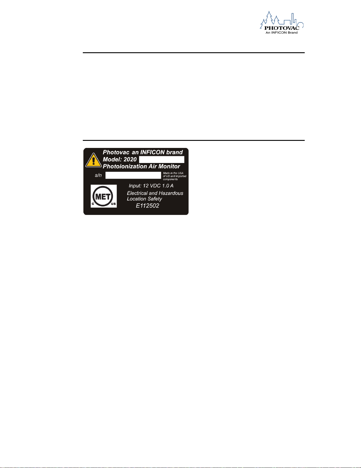
THE 2020ppbPRO IS CLASSIFIED FOR USE IN CLASS I, DIVISION 1, GROUPS
A, B, C, D HAZARDOUS LOCATIONS. T4 (135°C) RATING.
It has been listed by MET Laboratories, Inc., to comply with Underwriters
Laboratories® Inc. UL® 913 Standard for Intrinsically Safe Apparatus and
Associated Apparatus for use in Class I, Division 1, Groups A, B, C, D Hazardous
(Classified) Locations, Sixth Edition when powered by MX700010 or MX700011
Battery Pack. THE 2020ppbPRO IS NOT INTENDED TO DETECT COMBUSTIBLE
LEVELS OF GASES. THE 2020ppbPRO IS CLASSIFIED FOR USE IN
ATMOSPHERES CONTAINING COMBUSTIBLE LEVELS OF GASES.
These accessories are for use with the 2020ppbPRO in a hazardous location:
MX350006 Calibration Regulator
MX350007 Wrist Strap
MX750011 Belt-Clip Holster
MX700260 Carrying Case
M1760148 User’s Reference Card
MX380305 Long Sample Probe
MX395001 Short Sample Probe
A1790500 Tube Holder
F1760160 Dräger Tube, Carbon filter
F1760162 Dräger Tube, Intake sample conditioner
Do not use any other accessories with the 2020ppbPRO in a hazardous location.
Substitution of components may affect safety rating.
ISP-074-576-P1D 3
Page 10

WARNING
To reduce the risk of fire or injury to persons, read and
follow these instructions:
1. All calibration, maintenance and servicing of this
device, including battery charging, must be
performed in a safe area away from hazardous
locations. Disconnect all power before servicing.
2. There are no operator replaceable parts inside
the 2020ppbPRO except the battery pack, UV
lamp and sample inlet filter.
3. There are no operator serviceable parts inside
the 2020ppbPRO.
Do not use any other accessories with the 2020ppbPRO in a hazardous location.
Substitution of components may affect safety rating.
4 ISP-074-576-P1D
Page 11

CAUTION
1. For replacement battery pack use only Part No.
MX700010 or MX700011.
2. Do not dispose of the battery pack in a fire. The
cells may explode. The battery pack must be
disposed of properly. Check with local codes for
possible special disposal instructions.
3. Do not open or mutilate the battery pack. If the
2020ppbPRO is used in a manner not
specified, the protection provided by the
2020ppbPRO may be impaired.
4. Exercise care in handling battery packs in order
not to short the terminals with conducting
materials such as rings, bracelets and keys. The
battery or conductor may overheat and cause
burns.
5. Do not defeat proper polarity orientation
between the battery pack and battery
charger.
6. Charging the battery is only to be done in a nonhazardous area.
7. Charge the battery pack using the AC adapter
provided with or identified for use with this
product only in accordance with the instructions
and limitations specified in this manual. For AC
adapter use only Part No. MX350002 (115 Volts
AC), MX396013 (220 Volts AC). When using the
AC adapter do not block access to AC outlet in
use with adapter. AC adapter is not to be used
in a hazardous area.
ISP-074-576-P1D 5
Page 12

ATTENTION
Pour réduire le risque de feu ou blessures, lisez
attentivement ces directive:
1. Tout étalonnage et entretien, incluant le
chargement de la batterie, doit être fait dans un
endroit sécuritaire et non-explosif. L’alimentation
électrique doit être mis hors-service.
2. Aucune pièce ne peut être changée par
l’utilisateur à part la batterie.
3. Aucun entretien ne peut être fait par l’utilisateur.
ATTENTION
2020ppbPRO EST CLASSIFIÉ POUR USAGE DANS LES EMPLACEMENTS
DANGEREUX DE CLASSE I, DIVISION 1, GROUPES A, B, C, D. ÉVALUATION T4
(135ºC).
2020ppbPRO est conforme à la norme des Underwriters Laboratories Inc. UL 913
Standard for Intrinsically Safe Apparatus and Associated Apparatus for use in Class
I, Division 1, Groups A, B, C, D Hazardous (Classified) Locations. Quatrième
édition.
2020ppbPRO est conforme à la norme de CSA E79-0:1995 & CAS E79-11:1995:
Intrinsically Safe Equipment.
2020ppbPRO EST NE PAS INTENDER POUR DÉTECTER DES NIVEAUX DE
COMBUSTION DES GAZ. CET APPAREIL EST CLASSIFIÉ POUR USAGE DANS
DES ATMOSPHÈRES CONTENANT DES NIVEAUX DE COMBUSTION DES GAZ.
Les accessoires suivants peuvent également être utilisés avec l’appareil dans un
emplacement dangereux:
MX350006 Régulateur de calibration
MX350007 Sangle de poignet
MX750011 Étui de ceinture
MX700260 Étui de transport
M1760148 Carte de référence
MX380305 Gamme d’échantillons
MX395001 Petite Gamme d’échantillons
A1790500 Tube Holder
F1760160 Dräger Tube, Carbon filter
F1760162 Dräger Tube, Intake sample conditioner
Ne pas utiliser d’autres accessoires avec cet appareil dans un emplacement
dangereux. La substitution des composantes peut nuire à la sécurité d’emploi.
6 ISP-074-576-P1D
Page 13

ATTENTION
1. Utilisez seulement des batteries rechargeables de
type nickel cadmium avec un chargeur 12 Volts
DC (Pièce # MX700010 ou MX700011).
2. Ne jetez pas les batteries dans le feu. Elles
pourraient exploser Vérifiez avec la
réglementation locale avant d’en disposer.
3. Ne pas ouvrir ou briser la batterie. La protection
offerte par le 2020ppbPRO sera alors inutile.
4. La manutention de la batterie nécessite d’éviter
les produits conducteurs comme des anneaux,
bracelets ou clés pour éviter tout court- circuit La
batterie pourrait surchauffer et causer des
brûlures.
6. Ne pas modifier la polarité entre la batterie et le
chargeur.
7. Utilisez seulement l’adaptateur AC spécifié dans
le manuel. (Pièces # MX350002 (115 Volts AC),
MX396013 (220 Volts AC)). Ne pas bloquer la
sortie de l’adaptateur AC.
ISP-074-576-P1D 7
Page 14

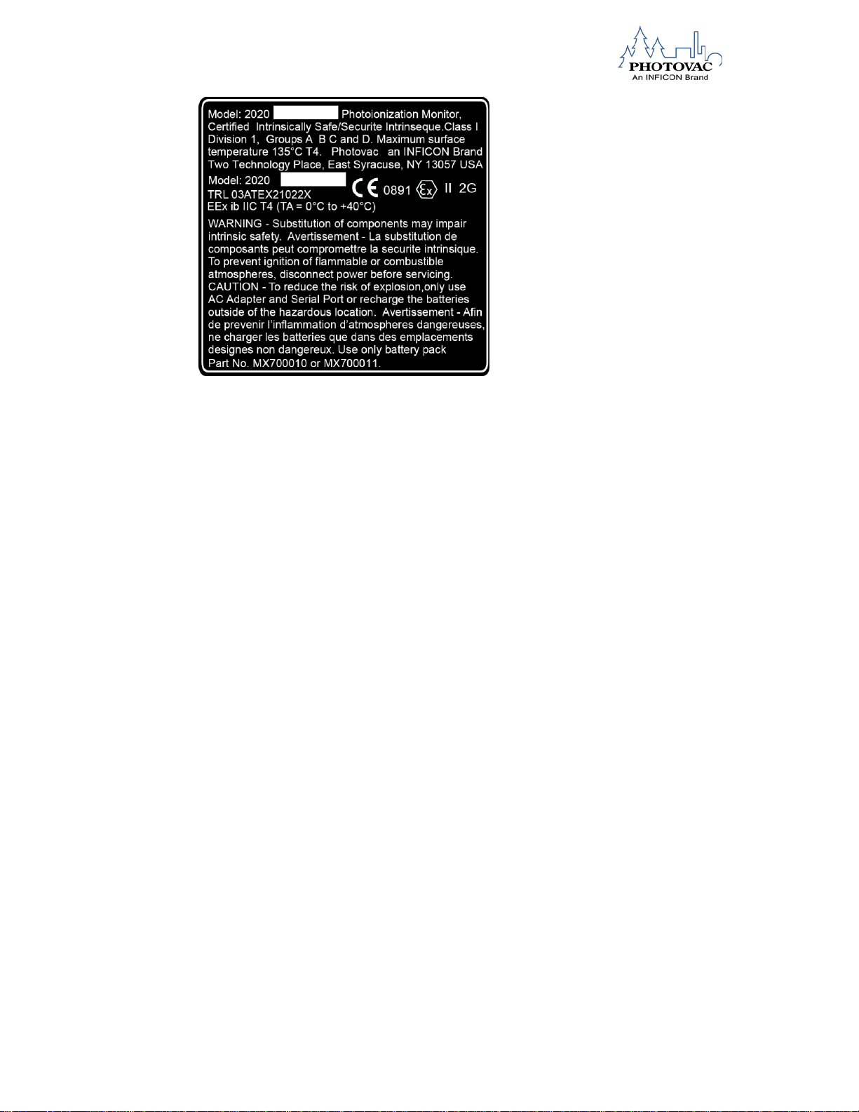
ATEX Directive and EMC Directive
We INFICON, Inc.
2 Technology Place
East Syracuse, NY 13057 USA
declare that: Equipment: Photoionization Monitor
Model names: 2020PRO, 2020PROPlus, 2020ppbPRO,
2020gasPRO, and 2020ComboPRO
In accordance with the following directives:
94/9/EEC: ATEX Directive
2006/95/EC: Low Voltage Directive
2004/108/EC: The Electromagnetic Compatibility Directive
Has been designed and manufactured to the following standards:
Safety: EN61010-1:2004
EMC: EN61326-1:2006
Explosive Atmosphere: EN50014:1997/A2:1999 EN50020:2002
EC Type Examination Certificate #: TRL03ATEX21022X
II 2G EEx ib IIC T4, Tamb= 0ºC to +40ºC
ATEX Certified by TRaC Global Ltd. of Unit 1, Pendle Place, Skelmersdale,
West Lancashire, WN8 9PN, UK
I hereby declare that the equipment named above has been designed to
comply with the relevant sections of the above referenced standards and all
essential requirements of the Directives.
Signed by:
Name: Stephen Chabot
Title: Vice President of Operations and Quality
Done at East Syracuse, NY USA
On 1 May 2012
8 ISP-074-576-P1D
Page 15
WARNING
1. All calibration, maintenance and servicing of this device, including battery
charging, must be performed in a safe area away from hazardous locations.
2. Disconnect all power before servicing.
3. Do not open UV Lamp Cap when unit is energized.
4. Only use the AC Adapter in a safe area away from hazardous locations
5. Only use the Serial Port in a safe area away from hazardous locations.
CAUTION
To reduce the risk of fire or injury to persons, read and follow these instructions:
1. There are no operator replaceable parts inside the 2020ppbPRO except the
battery pack, UV lamp and sample inlet filter.
2. For replacement battery pack use only Part No. MX700010 or MX700011.
3. There are no operator serviceable parts inside the 2020ppbPRO.
4. Do not dispose of the battery pack in a fire. The cells may explode. The battery
pack must be disposed of properly. Check with local codes for possible special
disposal instructions.
5. Do not open or mutilate the battery pack. If the 2020ppbPRO is used in a
manner not specified, the protection provided by the 2020ppbPRO may be
impaired.
6. Exercise care in handling battery packs in order not to short the terminals with
conducting materials such as rings, bracelets and keys. The battery or
conductor may overheat and cause burns.
7. Do not defeat proper polarity orientation between the battery pack and battery
charger.
8. Charge the battery pack using the AC adapter provided with or identified for use
with this product only in accordance with the instructions and limitations
specified in this manual. For AC adapter use only Part No. MX350002 (115
Volts AC), MX396013 (220 Volts AC). When using the AC adapter do not block
access to AC outlet in use with adapter. AC adapter is not to be used in a
hazardous area.
ISP-074-576-P1D 9
Page 16

These optional accessories may be used with the 2020ppbPRO in a hazardous
location:
MX350006 Calibration Regulator
MX350007 Wrist Strap
MX750011 Belt-Clip Holster
MX700260 Carrying Case
M1760148 User’s Reference Card
MX380305 Long Sample Probe
MX395001 Short Sample Probe
A1790500 Tube Holder
F1760160 Dräger Tube, Carbon filter
F1760162 Dräger Tube, Intake sample conditioner
Do not use any other accessories with the 2020ppbPRO in a hazardous location.
EM Warnhinweis
Dieses Gerät wurde geprüft und die Einhaltung der Grenzwerte hinsichtlich der
Aussendung von elektromagnetischen Wellen für ein digitales Gerät der Klasse B
nach Subpart B, Klasse B von Teil 15 der EMV Richtlinie bestätigt. Diese
Grenzwerte sind so festgelegt, dass bei Verwendung des Geräts in einer IndustrieUmgebung Störungen weitestgehend ausgeschlossen sein sollten. Dieses Gerät
erzeugt und arbeitet mit Radiowellen und kann diese auch emittieren und somit
Störungen des Funkverkehrs hervorrufen, wenn es nicht gemäß der
Betriebsanleitung eingebaut und verwendet wird. In Wohngebieten können jedoch
Störungen durch den Betrieb dieses Gerätes nicht ausgeschlossen werden. In
diesem Fall liegt es in der Verantwortung des Anwenders diese Störungen auf seine
Kosten zu beseitigen.
Hinweis zur Eigensicherheit (I/S) des 2020ppbPRO
Das 2020ppbPRO IST KLASSIFIZIERT ZUR VERWENDUNG IN
ARBEITSBEREICHEN MIT EXPLOSIBLER ATMOSPHÄRE (=EX-ZONEN) DER
KLASSE I, ABSCHNITT 1, GRUPPEN A, B, C, D KlasseT4 (Zündtemperatur bis
135°C).
Es entspricht der Norm für zugelassene Geräte zur Verwendung in Ex-Zonen der
Klasse 1, Abschnitt 1, Gruppen A, B, C, D (Standard for Intrinsically Safe Apparatus
and Associated Apparatus for use in Class I, Division 1, Groups A, B, C, D
Hazardous (Classified) Locations) der Underwriters Laboratories® Inc. UL® 913, 6.
Ausgabe.
Das 2020ppbPRO IST NICHT ZUR MESSUNG VON BRENNBAREN GASEN
VORGESEHEN, SONDERN FÜR DEN EINSATZ IN UMGEBUNGEN, DIE BRENNBARE GASE ENTHALTEN KÖNNEN.
10 ISP-074-576-P1D
Page 17

Das nachfolgend aufgeführte Zubehör kann für das 2020ppbPRO in
VORSICHT
Um das Brandrisiko oder das Verletzungsrisiko für Personen zu
verringern, sind die folgenden Anweisungen aufmerksam zu
lesen und zu befolgen:
1. Jede Kalibrierung, Wartung und Instandhaltung dieses
Geräts, sowie das Laden des Akkus muss an einem
sicheren Ort außerhalb von explosionsgefährdeten
Bereichen (Ex-Zonen) ausgeführt werden. Vor und
während einer Wartung ist die Verbindung des Gerätes
zur Stromversorgung zu unterbrechen.
2. Die vom Anwender des 2020ppbPRO auszutauschenden Teile beschränken sich auf:
- den Akku, - die UV-Lampe und
- das Probenahmefilterplättchen.
3. Im Inneren 2020ppbPRO befinden sich keine Teile, die
vom Endanwender zu warten sind..
explosionsgefährdeten Bereichen (Ex-Zonen) verwendet werden:
MX350006 Kalibriergasdruckminderer (Kalibriergasregler)
MX350007 Handgelenksschlaufe
MX700260 Gürtelholster
MX700260 Gerätetragekoffer
M1760148 Karte mit Kurzbedienungsanleitung
MX395001 Probenahmesonde
In explosionsgefährdeten Bereichen (Ex-Zonen) darf keinesfalls anderes Zubehör
des 2020ppbPRO eingesetzt werden.
Der Austausch von Bauteilen kann Ihre Sicherheit beeinträchtigen.
ISP-074-576-P1D 11
Page 18

WARNUNG
1. Als Ersatz-Akku nur das Originalersatzteil (Ni/Cd- Akku mit der TeileNr. MX700010 oder MX700011 ) verwenden.
2. Den Akku nicht in offenes Feuer werfen. Die Zelle kann explodieren.
Der Akku muss ordnungsgemäß entsorgt werden. Vor Ort nach den
Regelungen zur Entsorgung erkundigen
3. Den Akkupack nicht öffnen und nicht verändern. Manipulationen am
Akku haben den Verlust der Ex-Zulassung und erhebliche
Sicherheits-Risiken zur Folge.
4. Vorsichtig mit dem Akku umgehen und sicherstellen, dass die
Batteriekontakte nicht mit leitenden Materialien wie Ringen,
Armbändern oder Schlüsseln in Berührung kommen. Der Akku kann
überhitzen und Verbrennungen verursachen.
6. Auf richtige Zuordnung der Polarität zwischen Akku und Ladegerät
achten.
7. Den Akku mit dem mitgelieferten Netzgerät nur gemäß den in dieser
Betriebsanleitung spezifizierten Anweisungen und Einschränkungen
laden. Nur Original-Netzgerät (Teile-Nr:MX396013) verwenden. Bei
Verwendung des Netzgeräts, den Zugang zur Wechselstromsteckdose nicht versperren.
8. Der Akku darf nur außerhalb von explosionsgefährdeten Bereichen
geladen werden.
WARNUNG
1. Jede Kalibrierung, Wartung und Instandhaltung dieses Geräts, sowie
das Laden des Akkus muss an einem sicheren Ort außerhalb von
explosionsgefährdeten Bereichen (Ex-Zonen) ausgeführt werden.
Vor der Wartung sind alle elektrischen Verbindungen zu trennen.
Keinesfalls den Zugang zur UV Lampe öffnen, während das Gerät
aufgeladen wird.
Das Netzgerät nur außerhalb von explosionsgefährdeten Bereichen (Ex-
Zonen) einsetzen.
2. Die serielle Schnittstelle (RS232C) nur außerhalb von
explosionsgefährdeten Bereichen (Ex-Zonen) verwenden.
12 ISP-074-576-P1D
Page 19

VORSICHT
Um die Gefahr eines Brandes oder die Verletzung von Personen zu
reduzieren, lesen und befolgen Sie die folgenden Anweisungen:
1. Die vom Anwender des 2020ppbPRO auszutauschenden Teile
beschränken sich auf:
- den Akku, - die UV-Lampe und
- das Probenahmefilterplättchen.
2. Als Ersatz-Akku nur das Originalersatzteil (Ni/Cd- Akku mit der
Teile-Nr. MX700010 oder MX700011) verwenden
3. Den Akku nicht in offenes Feuer werfen. Die Zelle kann
explodieren. Der Akku muss ordnungsgemäß entsorgt werden. Vor
Ort nach den Regelungen zur Entsorgung erkundigen
4. Den Akkupack nicht öffnen und nicht verändern. Manipulationen am
Akku haben den Verlust der Ex-Zulassung und erhebliche
Sicherheits-Risiken zur Folge.
5. Vorsichtig mit dem Akku umgehen und sicherstellen, dass die
Batteriekontakte nicht mit leitenden Materialien wie Ringen,
Armbändern oder Schlüsseln in Berührung kommen. Der Akku
kann überhitzen und Verbrennungen verursachen.
6. Auf richtige Zuordnung der Polarität zwischen Akku und Ladegerät
achten.
7. Den Akku mit dem mitgelieferten Netzgerät nur gemäß den in
dieser Betriebsanleitung spezifizierten Anweisungen und Einschränkungen laden. Nur Original-Netzgerät (Teile-Nr. MX396013)
verwenden. Bei Verwendung des Netzgeräts, den Zugang zur
Wechselstromsteckdose nicht versperren.
Das nachfolgend aufgeführte Zubehör für das 2020ppbPRO kann in
explosionsgefährdeten Bereichen (Ex-Zonen) verwendet werden
MX350006 Kalibriergasdruckminderer (Kalibriergasregler)
MX350007 Handgelenksschlaufe
MX700260 Gürtelholster
MX700260 Gerätekoffer
M1760148 Karte mit Kurzbedienungsanleitung
MX395001 Probenahmesonde
MX395001 Probenahmeschlauch
Verwenden Sie für das 2020ppbPRO kein anderes Zubehör in explosions
gefährdeten Bereichen.
The 2020ppbPRO Intrinsic Safety (I/S) Notice
THE 2020ppbPRO IS CLASSIFIED FOR USE IN CLASS I, DIVISION 1, GROUPS
A, B, C, D HAZARDOUS LOCATIONS. T4 (135°C) RATING.
It has been listed by MET® to comply with Underwriters Laboratories® Inc. UL® 913
Standard for Intrinsically Safe Apparatus and Associated Apparatus for use in Class
I, Division 1, Groups A, B, C, D Hazardous (Classified) Locations, Sixth Edition
when powered by MX700010 or MX700011 Battery Pack. THE 2020ppbPRO IS
NOT INTENDED TO DETECT COMBUSTIBLE LEVELS OF GASES. THE
2020ppbPRO IS CLASSIFIED FOR USE IN ATMOSPHERES CONTAINING
COMBUSTIBLE LEVELS OF GASES.
ISP-074-576-P1D 13
Page 20

BEMÆRK
For minimering af risiko for brand samt skade på personer læs
og følg denne instruktion:
1. Kalibrering, vedligeholdelse, service, batteriskift og
opladning af batterier må ikke foretages i EXklassificeret område.
2. Det er kun batteripakke, UV lampe og sample filter,
som skiftes af burger.
3. Der er indvendig i 2020ppbPRO ikke udskiftelige
servicedele for bruger.
Dette tilbehør må anvendes med 2020ppbPRO i EX- klassificeret område i henhold
til ovenfor beskrevet:
MX350006 Kalibreringsgas Regulator
MX350007 Håndrem
MX700260 Bæltetaske
MX700260 Field kit taske.
M1760148 Bruger reference kort
MX395001 Kort sampleprobe
Anvend ikke andet tilbehør til 2020ppbPRO i EX-klassificeret område.
Anvendes ikke originale komponenter kan det påvirke
sikkerhedsklassificeringen.
14 ISP-074-576-P1D
Page 21

ADVARSEL
1. For erstatnings batteripakke anvend kun Part Nr.
MX700010 eller MX700011
2. Følge den lokale ordning for afskaffelse af batterier.
Batterier kan eksplodere ved brand.
3. Åben eller beskadig ikke batteripakken. Hvis
2020ppbPRO ikke anvendes som specificeret
bliver sikkerheden forringet.
4. Udøv forsigtighed med batteripakken. Pas på med
ringe, armbånd, nøgler m.m. disse ting kan
kortslutte batteripakken og overophede denne,
således den bryder i brand.
5. Forhindre ikke korrekt polarisering mellem
batteripakken og oplader.
6. Opladning må ikke ske i Ex-klassificeret område.
7. Opladning af instruments batteripakke eller brug af
220V AC oplader skal ske i overensstemmelse
med instruktion og begrænsninger, som beskrevet i
denne manual. Anvend kun oplader MX396013
(220V AC). Oplader må ikke anvendes i Exklassificeret område.
ADVARSEL
1. Al kalibrering, vedligeholdelse og service af instrument,
dette inkludere opladning, må ske i ikke Ex-klassificeret
område.
2. Service må ikke foretages under opladning eller med
startet/tændt instrument.
3. Fjern ikke dæksel til uV-lampe mens denne er tændt.
4. Opladning må kun ske udenfor Ex-klassificeret område..
5. Anvend kun instruments serielle udgang udenfor Exklassificeret område.
BEMÆRK
For minimering af risiko for brand samt skade på personer læs og følg denne
instruktion:
1. Det er kun batteripakke, UV lampe og sample filter, som skiftes af burger.
2. For erstatnings batteripakke anvend kun Part Nr. MX700010 eller MX700011
3. Der er indvendig i 2020ppbPRO s ikke udskiftelige servicedele for bruger.
ISP-074-576-P1D 15
Page 22

4. Følge den lokale ordning for afskaffelse af batterier. Batterier kan eksplodere
ved brand.
5. Åben eller beskadig ikke batteripakken. Hvis 2020ppbPRO ikke anvendes som
specificeret bliver sikkerheden forringet.
6. Udøv forsigtighed med batteripakken. Pas på med ringe, armbånd, nøgler m.m.
disse ting kan kortslutte batteripakken og overophede denne, således den bryder i
brand.
7. Forhindre ikke korrekt polarisering mellem batteripakken og oplader
8. Opladning af instruments batteripakke eller brug af 220V AC oplader skal ske i
overensstemmelse med instruktion og begrænsninger, som beskrevet i denne
manual. Anvend kun oplader MX396013 (220V AC). Oplader må ikke anvendes i
Ex-klassificeret områd.e
Dette tilbehør må anvendes med 2020ppbPRO i EX- klassificeret område i henhold
til ovenfor beskrevet:
MX350006 Kalibrerings Regulator
MX350007 Håndrem
MX700260 Bæltetaske
MX700260 Field kit taske.
M1760148 Bruger reference kort
MX395001 Kort sampleprobe
16 ISP-074-576-P1D
Page 23

FCC Waarschuwing
VOORZICHTIG Lees en volg deze instructies op om het risico op brand of
verwonding van personen te reduceren: 1. Alle kalibratie, onderhoud en
servicewerkzaamheden aan dit apparaat, inclusief het opladen van de
batterij, moet altijd plaats vinden in een veilige zone, uit de buurt van
explosiegevaarlijke gebieden. Ontkoppel alle voeding voordat u
servicewerkzaamheden uitvoert. 2. Er zijn geen onderdelen in de
2020ppbPRO die door de operator vervangen kunnen worden, behalve
het batterij
Deze apparatuur is getest en er is geconcludeerd dat deze voldoet aan de
grenswaarden voor een Class B Digital Device, conform Subpart B, Class B van
Part 15 van de FCC regels. Deze grenswaarden zijn bedoeld om een redelijke
bescherming te bieden tegen schadelijke interferentie wanneer deze apparatuur
wordt gebruikt in een commerciële omgeving. Deze apparatuur, genereert, gebruikt
en kan radiofrequentie-energie uitstralen. Indien niet juist geïnstalleerd en gebruikt
in overeenstemming met de gebruikershandleiding, kan dit leiden tot schadelijke
interferentie met radiocommunicatie. Bediening van deze apparatuur in een
woonwijk kan leiden tot schadelijke interferentie, in welk geval de gebruiker de
interferentie op eigen kosten moet verhelpen.
De 2020ppbPRO intrinsiekveilig (I/S) mededeling
DE 2020ppbPRO IS GOEDGEKEURD VOOR GEBRUIK IN CLASS I, DIVISION 1,
GROUPS A, B, C, D EXPLOSIEGEVAARLIJKE GEBIEDEN. T4 (135°C)
CLASSIFICATIE. Het is geregistreerd door MET® als instrument dat voldoet aan de
Standard for Intrinsically Safe Apparatus and Associated Apparatus for use in Class
I, Division 1, Groups A, B, C, D Hazardous (Classified) Locations, Sixth Edition van
Underwriters Laboratories® Inc. UL® 913 indien gevoed door een MX700010 or
MX700011 batterij-pack. DE 2020ppbPRO IS NIET BEDOELD VOOR DETECTIE
VAN ONTBRANDBARE GASNIVEAUS.DE 2020ppbPRO IS GECLASSIFICEERD
VOOR GEBRUIK IN ATMOSFEREN DIE ONTBRANDBARE GASNIVEAUS
BEVATTEN.
Deze accessoires zijn bedoeld voor gebruik met de 2020ppbPRO in een
explosiegevaarlijk gebied::
MX350006 Kalibratieregelaar
MX350007 Polsband
MX700260 Riem clip-holster
MX700260 Draagkoffer
M1760148 Gebruikers referentiekaart
MX395001 Korte monsternameslang
Gebruik geen andere accessoires in combinatie met de 2020ppbPRO in een
explosiegevaarlijke locatie. Vervanging van componenten kan invloed hebben op de
veiligheidsclassificatie.
ISP-074-576-P1D 17
Page 24

WAAR-SCHUWING
1. Gebruik als vervangend batterij-pack uitsluitend artikelnr.Part No.
MX700010 of MX700011.
2. Gooi het batterij-pack niet in een vuur. De cellen kunnen exploderen. Het
batterij-pack moet correct worden afgevoerd. Verifieer de lokale regelgeving voor
instructies voor de afvoer van dergelijk afval.
3. Open of beschadig het batterij-pack niet. Wanneer de 2020ppbPRO wordt
gebruikt op een wijze die niet is gespecificeerd, dan kan de bescherming die wordt
geboden door de 2020ppbPRO gevaar lopen.
4. Wees voorzichtig met het omgaan met batterij-pack. Let er op dat de
contacten niet kortsluiten met geleidende materialen zoals ringen, armbanden en
sleutels. De batterij of geleider kan oververhit raken en brandwonden veroorzaken.
5. Let op de juiste polariteit tussen het batterij-pack en de lader.
6. De batterij mag uitsluitend worden geladen in een niet explosiegevaarlijk
gebied.
7. Laad het batterij-pack met de meegeleverde AC-adapter, of speciaal voor
dit product aangewezen adapter, uitsluitend conform de instructies en beperkingen
die worden gespecificeerd in deze handleiding. Gebruik voor AC-adapter uitsluitend
artikelnr.. MX396013 (220 Volt AC). bij het gebruik van de AC-adapter niet de
toegang tot de AC wandcontactdoos die wordt gebruikt voor de adapter. De ACadapter mag niet worden gebruikt in een explosiegevaarlijk gebied.
Waarschuwing
1. Alle kalibratie, onderhoud en servicewerkzaamheden aan dit apparaat,
inclusief het opladen van de batterij, moet altijd plaats vinden in een veilige zone, uit
de buurt van explosiegevaarlijke gebieden.
2. Ontkoppel alle voeding voordat u servicewerkzaamheden uitvoert.
3. Open de UV Lamp kap niet wanneer de eenheid is ingeschakeld.
4. Gebruik de AC-adapter uitsluitend in een veilig gebied, uit de buurt van
explosiegevaarlijke gebieden.
5. Gebruik de Seriële poort uitsluitend in een veilig gebied, uit de buurt van
explosiegevaarlijke gebieden.
Voorzichtig
Lees en volg deze instructies op om het risico op brand of verwonding van personen
te reduceren:
1. Er zijn geen onderdelen in de 2020ppbPRO die door de operator vervangen
kunnen worden, behalve het batterij-pack, de UV lamp en monsterinlaatfilter.
Gebruik als vervangend batterij-pack uitsluitend artikelnr. MX700010 of
MX700011.
18 ISP-074-576-P1D
Page 25

2. Er zijn geen onderdelen binnenin de 2020ppbPRO s die door de operator kunnen
worden onderhouden.
3. Gooi het batterij-pack niet in een vuur. De cellen kunnen exploderen. Het batterij-
pack moet correct worden afgevoerd. Verificeer de lokale regelgeving voor
instructies voor de afvoer van dergelijk afval.
4. Open of beschadig het batterij-pack niet. Wanneer de 2020ppbPRO wordt
gebruikt op een wijze die niet is gespecificeerd, kan de bescherming die wordt
geboden door de 2020ppbPRO gevaar lopen.
5. Wees voorzichtig met het omgaan met batterij-pack. Let er op dat de contacten
niet kortsluiten met geleidende materialen zoals ringen, armbanden en
sleutels. De batterij of geleider kan oververhit raken en brandwonden
veroorzaken.
6. Let op de juiste polariteit tussen het batterij-pack en de lader.
7. Laad het batterij-pack met de meegeleverde AC-adapter, of speciaal voor dit
product aangewezen adapter, uitsluitend conform de instructies en
beperkingen die worden gespecificeerd in deze handleiding. Gebruik voor ACadapter uitsluitend artikelnr, MX396013 (220 Volt AC). Blokkeer, bij het gebruik
van de AC-adapter niet de toegang tot de AC wandcontactdoos die wordt
gebruikt voor de adapter. De AC-adapter mag niet worden gebruikt in een
explosiegevaarlijk gebied.
Deze accessoires zijn bedoeld voor gebruik met de 2020ppbPRO in een
explosiegevaarlijk gebied::
MX350006 Kalibratieregelaar
MX350007 Polsband
MX700260 Riem clip-holster
MX700260 Draagkoffer
M1760148 Gebruikers referentiekaart
MX395001 Korte monsternameslang
Gebruik geen andere accessoires in combinatie met de 2020ppbPRO in een
explosiegevaarlijke locatie. Vervanging van componenten kan invloed hebben op de
veiligheidsclassificatie.
ISP-074-576-P1D 19
Page 26

Avertissement Compatibilité électromagnétique
Cet équipement a été testé et reconnu conforme aux limitations de la Classe B des
équipements numériques, conformément au sous-paragraphe B, Classe B du
paragraphe 15 des règles FCC. Ces limites sont conçues pour fournir une protection
raisonnable à l’encontre des interférences nuisibles lorsque l’équipement est utilisé
dans un environnement industriel.
Cet équipement génère, utilise et peut émettre de l’énergie sous forme de
fréquences radio et, si non installé et utilisé en conformité avec les instructions de
ce manuel, peut entraîner des interférences nuisibles aux communications radio.
L’utilisation de cet appareil dans une zone résidentielle peut entraîner des
interférences nuisibles auquel cas, l’utilisateur sera obligé de corriger les
interférences à ses propres frais.
2020ppbPRO - Note de sécurité intrinsèque
LE 2020ppbPRO EST CLASSIFIE POUR UN USAGE EN ZONES DANGEREUSES
DE CLASSE I, DIVISION I, GROUPES A, B, C, D. T4 EVALUTATION (135 °C).
Le 2020ppbPRO est conforme à la norme des Underwriters Laboratories Inc. UL
913 Standard for Intrinsically Safe Apparatus and Associated for use in Class I,
Division I, Groups A, B, C, D Hazardous (Classified) Locations. Quatrième édition.
Le 2020ppbPRO est conforme à la norme CSA E79-0:1995 & CAS E79-11:1995:
Intrinsically Safe Equipment.
LE 2020ppbPRO N’EST PAS PREVU POUR DETECTER DES NIVEAUX DE
COMBUSTION DE GAZ. LE 2020ppbPRO EST CLASSE POUR ETRE UTILISE EN
ATMOSPHERES CONTENANT DES NIVEAUX DE COMBUSTION DE GAZ.
Les accessoires suivants peuvent également être utilisés avec le 2020ppbPRO en
zone dangereuse :
MX350006 Régulateur d’étalonnage.
MX350007 Dragonne.
MX700260 Etui de ceinture
MX700260 Valise de transport
M1760148 Carte de référence utilisateur
MX395001 Sonde d’échantillonnage courte
N’utilisez aucun autre accessoire avec le 2020ppbPRO en zone dangereuse.
L’échange de composants peut altérer le niveau de sécurité.
AVERTISSEMENT
Pour réduire le risque d’incendie ou de blessure aux personnes, lisez et suivez les
instructions ci-dessous.
1. Tout étalonnage, maintenance ou entretien de cet équipement, y compris la
recharge des batteries, doit être réalisé dans une zone de sécurité et éloignée
de toutes zones dangereuses. Déconnecter toute source d’alimentation avant
toute intervention de maintenance.
2. Exceptés la batterie, la lampe UV et le filtre d’entrée d’échantillonnage, aucune
autre pièce du 2020ppbPRO ne peut être remplacée par l’opérateur.
3. Le2020ppbPRO ne contient aucune pièce réparable par l’utilisateur.
20 ISP-074-576-P1D
Page 27

ATTENTION
1. Pour le remplacement de la batterie, n’utilisez que la batterie référence
MX700010 ou MX700011.
2. Ne jetez pas le bloc batterie au feu. Les cellules peuvent exploser. Le bloc
batterie doit être jeté conformément à la réglementation locale. Vérifiez la
présence de contraintes locales spécifiques éventuelles.
3. N’ouvrez ni ne désagrégez la batterie. Si le 2020ppbPRO est utilisé d’une
façon non prévue, la protection fournie par le2020ppbPRO peut être altérée.
4. Soyez prudent lors de la manipulation des blocs batterie de manière à ne pas
court-circuiter les bornes avec des objets tels que bague, bracelets ou clefs. La
batterie ou le conducteur peut surchauffer et engendrer des brûlures.
5. Ne pas inverser les polarités entre la batterie et son chargeur.
6. La recharge de la batterie ne devra être effectuée que dans une zone non
dangereuse.
7. Chargez le bloc batterie en utilisant l’adaptateur pour courant alternatif fourni
ou identifié pour l’utilisation pour ce produit uniquement, en conformité avec les
instructions et limitations spécifiées dans ce manuel. Pour l’adaptateur pour
courant alternatif, n’utiliser que le produit référencé MX396013 (220 V AC).
Lors de l’utilisation de l’adaptateur pour courant alternatif, ne pas bloquer
l’accès à la sortie alternative en utilisation avec l’adaptateur. L’adaptateur pour
courant alternatif ne peut pas être utilisé dans une zone dangereuse.
ATTENTION
1. Tout étalonnage, maintenance et entretien de cet équipement, y compris la
recharge du bloc batterie, doit être réalisé dans une zone de sécurité
éloignée de toutes zones dangereuses.
2. Déconnecter toute source d’alimentation avant d’effectuer l’entretien.
3. Ne pas ouvrir le cache de la lampe UV avant d’avoir débrancher l’appareil.
4. N’utiliser un adaptateur pour courant alternatif que dans une zone de
sécurité éloignée de toutes zones dangereuses.
5. N’utiliser le port série que dans une zone de sécurité éloignée de toutes
zones dangereuses.
ISP-074-576-P1D 21
Page 28

ATTENTION
2020ppbPRO EST CLASSIFIÉ POUR USAGE DANS LES
EMPLACEMENTS DANGEREUX DE CLASSE I, DIVISION 1,
GROUPES A, B, C, D. ÉVALUATION T4 (135ºC).
2020ppbPRO est conforme à la norme des Underwriters
Laboratories Inc. UL 913 Standard for Intrinsically Safe
Apparatus and Associated Apparatus for use in Class I,
Division 1, Groups A, B, C, D Hazardous (Classified)
Locations. Quatrième édition.
2020ppbPRO est conforme à la norme de CSA E79-0:1995 &
CAS E79-11:1995: Intrinsically Safe Equipment.
2020ppbPRO EST NE PAS INTENDER POUR DÉTECTER
DES NIVEAUX DE COMBUSTION DES GAZ. CET
APPAREIL EST CLASSIFIÉ POUR USAGE DANS DES
ATMOSPHÈRES CONTENANT DES NIVEAUX DE
COMBUSTION DES GAZ.
Les accessoires suivants peuvent également être utilisés avec
l’appareil dans un emplacement dangereux:
MX350006 Régulateur de calibration
MX350007 Sangle de poignet
MX700260 Étui de ceinture
MX700260 Étui de transport
M1760148 Carte de référence
MX395001 Petite Gamme d’échantillons
Ne pas utiliser d’autres accessoires avec cet appareil dans un
emplacement dangereux.
La substitution des composantes peut nuire à la sécurité
d’emploi.
ATTENTION
Pour réduire le risque de feu ou blessures, lisez attentivement ces directive:
1. Tout étalonnage et entretien, incluant le chargement de la batterie, doit
être fait dans un endroit sécuritaire et non-explosif. L’alimentation électrique
doit être mis hors-service.
2. Aucune pièce ne peut être changée par l’utilisateur à part la batterie.
3. Aucun entretien ne peut être fait par l’utilisateur.
ATTENTION
1. Utilisez seulement des batteries rechargeables de type nickel cadmium
avec un chargeur 12 Volts DC (Pièce # MX700010 ou MX700011).
2. Ne jetez pas les batteries dans le feu. Elles pourraient exploser Vérifiez
avec la réglementation locale avant d’en disposer.
3. Ne pas ouvrir ou briser la batterie. La protection offerte par le 2020ppbPRO
sera alors inutile.
22 ISP-074-576-P1D
Page 29

4. La manutention de la batterie nécessite d’éviter les produits conducteurs
comme des anneaux, bracelets ou clés pour éviter tout court- circuit La
batterie pourrait surchauffer et causer des brûlures.
5. Ne pas modifier la polarité entre la batterie et le chargeur.
6. Utilisez seulement l’adaptateur AC spécifié dans le manuel. (Pièces #
MX396013 (220 Volts AC)). Ne pas bloquer la sortie de l’adaptateur AC.
ISP-074-576-P1D 23
Page 30

Advertencia FCC
Este equipo ha sido probado y se ha comprobado que cumple con los límites para
la clase B de los equipos digitales, en conformidad con la sub-parte B, clase B de la
parte 15 de las reglas FCC. Estos límites han sido determinados para proveer una
protección razonable contra interferencias cuando el equipo es operado en una
zona comercial. Este equipo genera, usa y puede radiar energía de radio frecuencia
y si no es usado de acuerdo con las instrucciones de este manual puede causar
interferencia para una radio de comunicación. La operación de este equipo en una
zona residencial probablemente causará interferencias que deben ser eliminadas
por cuenta del usuario.
Información sobre la seguridad intrínseca (I/S) del 2020ppbPRO
El 2020ppbPRO 2 ESTA CLASIFICADO PARA SER USADO EN ZONAS
PELIGROSAS DE LA CLASE I, DIVISIÓN 1, GRUPOS A, B, C, D. CLASE T4
(135°C).
Ha sido probado por MET® para cumplir con los estándares de seguridad de
Underwriters Laboratories® Inc. UL® 913 para aparatos intrínsicamente seguros y
aparatos asociados para su utilización en zonas (clasificadas ) de peligro en la
clase I, División 1, Grupos A, B, C, D, Sexta Edición cuando sea alimentado por un
paquete de baterías MX700010 o MX700011. EL 2020ppbPRO NO ESTA
DISEÑADO PARA DETECTAR NIVELES COMBUSTIBLES DE GASES. EL
2020ppbPRO ESTA CLASIFICADO PARA UTILIZARLO EN ATMÓSFERAS QUE
CONTENGA NIVELES COMBUSTIBLES DE GASES.
Los siguientes accesorios son utilizados con el 2020ppbPRO en zonas
clasificadas:
MX350006 Regulador de calibración
MX350007 Correa de mano
MX700260 Funda con clip para correa
MX700260 Maleta
M1760148 Tarjeta de referencia del usuario
MX395001 Sonda de toma de muestras.
No usar otros accesorios con el 2020ppbPRO en zonas peligrosas
La sustitución de componentes puede afectar el grado de seguridad.
CUIDADO
Para reducir el riesgo de incendios y daños personales, leer y seguir las siguientes
instrucciones:
1. La calibración, mantenimiento y servicio de este aparato, incluyendo el
cambio de baterías deben ser realizados en un área segura lejos de la zona de
peligro. Desconectar la alimentación de energía antes de empezar con los
trabajos de mantenimiento.
2. El 2020ppbPRO no cuenta con partes que deben ser reemplazadas por el
operador a excepción del paquete de baterías, la lámpara UV y el filtro de
entrada de la muestra.
3. El 2020ppbPRO 2 no cuenta con partes que deben ser mantenidas
directamente por el operador.
24 ISP-074-576-P1D
Page 31

ADVERTENCIA
1. Para reemplazar el paquete de baterías usar sólo la pieza nº. MX700010 o
MX700011.
2. No tirar el paquete de baterías en el fuego. Estas pueden explotar. El paquete
de baterías debe ser desechado adecuadamente. Averiguar si existen instrucciones
locales especiales como residuos.
3. No abrir o mutilar el paquete de baterías. Si el 2020ppbPRO se utiliza de una
manera no especificada, puede afectar la protección provista para el 2020ppbPRO.
4. Manipular el paquete de baterías con cuidado y asegúrese que los terminales
de ésta no entren en contacto con materiales conductores tales como anillos,
brazaletes y llaves. La batería o el conductor se pueden sobrecalentar y causar un
incendio.
5. No confundir la polaridad apropiada entre el paquete de baterías y el cargador.
6. La carga de la batería sólo debe realizarse en un área no peligrosa.
7. Cargar el paquete de baterías usando el adaptador AC suministrado o
señalado para ser usado sólo con este producto de acuerdo con las instrucciones y
limitaciones especificadas en este manual. Para el adaptador AC usar sólo la pieza
Nº. MX396013 (220 Voltios AC). Cuando se use el adaptador AC no bloquear el
acceso de la salida AC en uso con el adaptador. No usar el adaptador AC en áreas
peligrosas.
ADVERTENCIA
8. La calibración, mantenimiento y servicio de este aparato incluyendo el
cambio de baterías deben ser realizados en un área segura lejos de la zona
de peligro.
9. Desconectar la alimentación de energía antes de empezar con los trabajos
de mantenimiento.No abrir la cubierta de la lámpara UV cuando la unidad
está conectada a la alimentación de energía.
10. Utilizar el adaptador AC sólo en una zona segura lejos de zona peligrosas.
11. Utilizar el puerto serie sólo en una zona segura lejos de zonas peligrosas.
CUIDADO
Para reducir el riesgo de incendios y daños personales, leer y seguir las siguientes
instrucciones:
12. El 2020ppbPRO no cuenta con partes que puedan ser reemplazadas por el
operador a excepción del paquete de baterías, la lámpara UV y el filtro de
entrada de muestras.
13. Para reemplazar el paquete de baterías usar sólo la pieza original
nº. MX700010 o MX700011.
14. El 2020ppbPRO no cuenta con partes que deben ser reparadas
directamente por el operador.
15. No colocar el paquete de baterías en el fuego. Estas pueden explotar. El
paquete de baterías debe ser desechado adecuadamente. Averiguar si
existen instrucciones locales especiales como residuos.
ISP-074-576-P1D 25
Page 32

16. No abrir o mutilar el paquete de baterías. Si el 2020ppbPRO s es utilizado
de una manera no especificada la protección provista para el 2020ppbPRO
puede dañarse.
17. Manipular el paquete de baterías con cuidado y asegúrese que los
terminales de ésta no entren en contacto con materiales conductores
tales como anillos, brazaletes y llaves. La batería o el conductor se puede
sobrecalentar y causar un incendio.
18. No confundir la polaridad apropiada entre el paquete de baterías y el
cargador. Cargar el paquete de baterías usando el adaptador AC
suministrado o señalado para ser usado sólo con este producto de
acuerdo con las instrucciones y limitaciones especificadas en este
manual. Para el adaptador AC usar sólo la pieza Nº. MX396013 (220
Voltios AC). Cuando se use el adaptador AC no bloquear el acceso de la
salida AC en uso con el adaptador. No usar el adaptador AC en áreas
peligrosas.
Los siguientes accesorios son utilizados con el 2020ppbPRO en zonas
clasificadas:
MX350006 Regulador de calibración
MX350007 Correa de mano
MX700260 Funda con clip para correa
MX700260 Maleta
M1760148 Tarjeta de referencia del usuario
MX395001 Sonda de toma de muestras.
No usar otros accesorios con el 2020ppbPRO en zonas peligrosas
La sustitución de componentes puede afectar el grado de seguridad.
26 ISP-074-576-P1D
Page 33

FCC Avvertenze
FCC avverte che questa apparecchiatura è stata esaminata ed è idonea per
aderire ai limiti per un dispositivo del codice categoria B Digital, conforme a Subpart
B, codice categoria B della parte 15 delle regole del FCC. Questi limiti sono destinati
ad assicurare la protezione minima contro interferenza nociva quando
l'apparecchiatura è utilizzata in un ambiente commerciale. Questa apparecchiatura
genera, e può irradiare energia di frequenza radiofonica e se non usata in
conformità con il manuale d'istruzione, può causare interferenze alle comunicazioni
radio. L'impiego di queste attrezzature in una zona residenziale può causare
interferenze ed i relativi danni causati saranno totalmente a carico dell’utilizzatore .
The 2020ppbPRO Intrinsic Safety (I/S) Notice
Il 2020ppbPRO è certificato per usi in classe I, divisione 1, gruppi A, B, C, D luoghi
con rischio di esplosione . T4 (135°C).
È stato elencato da MET® per aderire al campione dei Underwriters Laboratories®
Inc. UL® 913 per l'apparecchio di per sè sicuro e l'apparecchio associato per uso
nel codice categoria I, divisione 1, gruppi A, B, C, posizioni (classificate) pericolose
di D, sesta edizione una volta alimentato dal pacco batteria.
IL 2020ppbPRO NON È INTESO PER RILEVARE I LIVELLI COMBUSTIBILI DEI
GAS.
IL 2020ppbPRO È CLASSIFICATO PER USO IN ATMOSFERA CHE
CONTENGONO I LIVELLI COMBUSTIBILI DEI GAS.
Questi accessori possono essere usati con il 2020ppbPRO in zona pericolosa:
MX350006 Adattatore di calibrazione
MX350007 Wrist Strap
MX700260 Cinghia - Clip
MX700260 Valigetta di trasporto
M1760148 Reference Card
MX395001 Sonda di campionamento
Non usare altri accessori con il 2020ppbPRO in zone pericolose . La sostituzione
dei componenti può avere effetti negativi sull’utilizzo dello stesso in completa
sicurezza.
CAUTELA
Per ridurre il rischio di infortuni e incidenti , leggere e seguire le seguenti istruzioni:
1. Tutti le calibrazioni, mantenimento ed assistenza di questo dispositivo, compreso
la verifica della batteria carica/ scarica , devono essere effettuati in una zona sicura.
Durante qualsiasi manutenzione lo strumento non deve essere alimentato.
2. Non ci sono parti sostituibili dell'operatore all'interno del 2020ppbPRO tranne il
pacchetto della batteria, la lampada UV ed il filtro all'ingresso del campione.
3. Non ci sono parti utili dell'operatore all'interno del 2020ppbPRO.
ISP-074-576-P1D 27
Page 34

Avvertenze
1. Per cambiare il pacco batteria usare solo il part number MX700010 o MX700011.
2. Non mettere il pacco batteria sul fuoco. Le celle possono esplodere. Le batterie
devono essere rottamate . Controllare I codici locali di rottamazione per possible
speciali istruzioni.
3. Non aprire o mutilare il pacco batteria . Un uso non corretto può alterare la
sicurezza dello strumento.
4. Prestare attenzione nel maneggiare la batteria al fine di non mettere in corto i
contatti . La batteria può scaldarsi toccare con cautela.
5. Non invertire le polarità della batteria .
6. Caricare le batterie solo in zone sicure .
7. Caricare la batteria solo con l’alimentatore in dotazione o utilizzare alimentatori
che rispettino i dati indicati sul manuale d’istruzione. Usare part number MX396013
( 220 Volts AC ). L’alimentatore non deve essere usate in zone pericolose.
28 ISP-074-576-P1D
Page 35

Introduction
2
ISP-074-576-P1D 29
Page 36

WARNING
A warning indicates an operation that could cause personal injury if
precautions are not followed.
CAUTION
A caution indicates an operation that could cause instrument
damage if precautions are not followed.
About this Manual
This manual provides detailed instructions for setup, operation and maintenance of
the 2020ppbPRO Portable Photoionization Monitor.
Before unpacking the instrument, please read Warnings and Safety Practices on
pages 4 and 5. This section describes possible hazards that might injure the user,
damage the instrument or compromise its operation. Some general safety
information is also provided.
To help you learn to use the 2020ppbPRO quickly, this manual is organized by tasks
beginning with:
Using the 2020ppbPRO in Chapter 3
Calibrating the 2020ppbPRO in Chapter 4
Accessories are covered in Chapter 5
Routine maintenance is covered in Chapter 6
Troubleshooting techniques are covered in Chapter 7
The 2020ppbPRO manual uses a few conventions for key names on the keypad and
for text that is shown on the display.
UPPERCASE Fixed key names are denoted by uppercase text.
“Display Text” Text that appears on the 2020ppbPRO status display is
in quotation marks.
Soft key names are also shown in quotation marks.
In the text you will find various warnings and notes.
NOTE: A note indicates significant information.
30 ISP-074-576-P1D
Page 37

Warnings and Safety Practices
WARNING
If the 2020ppbPRO you are using is not specifically identified as
intrinsically safe with a label on the 2020ppbPRO, do not use it in a
location where flammable concentrations of gases and vapors may
exist.
Please read the Notices and Warnings section of this user’s manual before
operating the 2020ppbPRO.
Approved Models of the 2020ppbPRO
This manual provides operational information for all models of the 2020ppbPRO.
The 2020ppbPRO is intrinsically safe and approved for use in hazardous locations.
Refer to the Notices and Warnings section of this manual for details of each
approval.
Throughout the manual, notes are provided to inform you of any limitations of usage
for the 2020ppbPRO models.
Excessive Heat and Cold
Do not expose the instrument to intense sunlight for prolonged periods.
Exposure to excessive heat or cold may result in erroneous readings.
ISP-074-576-P1D 31
Page 38

2020ppbPRO Overview
Figure 1. The 2020ppbPRO Instrument
The 2020ppbPRO measures the concentration of airborne gases and vapors that
can be ionized by a photoionization detector. The 2020ppbPRO automatically
displays and can record these concentrations. The 2020ppbPRO does not
distinguish between individual compounds. The reading displayed represents
the total concentration of all photoionizable chemicals present in the sample. The
2020ppbPRO displays concentrations in units of ppb as well as ppm and Mg/M3.
The 2020ppbPRO operates automatically. The 2020ppbPRO display updates itself
once per second. You can read concentrations directly from the display.
The 2020ppbPRO will perform short-term exposure limit (STEL), time-weighted
average (TWA) and PEAK calculations when it is in INTERVAL mode. You can view
any of these results in INTERVAL mode.
The 2020ppbPRO has two datalogging options, Tag and Interval mode. Tag mode
allows the user to manually tag and store readings during a walkthrough. Interval
mode allows the user to datalog at selectable intervals of 1 second to 999 seconds.
In Interval mode, the STEL, PEAK and TWA are calculated. If you select Interval
mode, these values are automatically recorded in the 2020ppbPRO’s memory. The
2020ppbPRO can log up to 12,000 entries.
32 ISP-074-576-P1D
Page 39

In Tag mode operation, the 2020ppbPRO prompts you to locate a site and then to
Inlet
Filter
Photoionization
Detector
Sample In
Sample Out
Display and
I/O Connector
Keypad
Microprocessor
Power
Supply
Electrical Connections
Gas Connections
Pump
record a background and sample readings for the site. You can record up to 12,000
manual entries. There is no averaging of data in Tag mode.
Recorded data can be reviewed on the display or downloaded to a computer. Data
are recorded by date and time.
The 2020ppbPRO has 5 keys for instrument operation. The keys are used to set up
and calibrate the 2020ppbPRO. All information entered with the keys and stored in
the 2020ppbPRO’s memory is retained when the instrument is switched off. The
clock and calendar continue to operate and do not need to be reset when the
2020ppbPRO is turned on.
General Operation
The 2020ppbPRO is a microprocessor-controlled air monitor for measuring the
presence of photoionizable compounds in air at parts-per-billion levels. The block
diagram in Figure 2 shows the main components of the 2020ppbPRO.
Figure 2. The 2020ppbPRO Block Diagram
The microprocessor controls the components of the instrument and interprets and
records the signal generated by the photoionization detector (PID). Recorded data
and setup information entered into the microprocessor’s memory are retained when
the 2020ppbPRO is turned off.
A pump continuously pulls the air under test through the 2020ppbPRO’s PID. The
PID converts the concentration of photoionizable compounds in the sample into an
electrical signal. The microprocessor subtracts any background from the signal and
divides this signal by a sensitivity obtained by calibrating with a standard gas of
known concentration. This concentration appears on the 2020ppbPRO’s display
and, depending on the values entered through the 2020ppbPRO’s keypad, an alarm
status may be displayed and an audio signal may be heard.
The 2020ppbPRO can detect thousands of different types of airborne gases and
vapors and its response depends on the characteristics as well as the concentration
of each compound.
The 2020ppbPRO does not distinguish one type of compound from another,
but displays a number indicating the total concentration of all photoionizable
compounds in the sample.
ISP-074-576-P1D 33
Page 40

M
M
M
M
M
M
e
+
-
++h
Lamp Power
Supply
Lamp Driver
Circuit
Microprocessor
Light Sensor
Electrometer
+125 Volts
Sample In
Detector Cell
UV Lamp
Lampholder
High Voltage
Plates
Sample Out
UV Lamp
UV Light
Sample
Ionized Molecule
Collector Electrode
Repeller Electrode
A standard of isobutylene at a known concentration may be used for setting the
sensitivity. If the 2020ppbPRO is calibrated with isobutylene, it displays
concentrations in units equivalent to ppm of isobutylene. If isobutylene were the only
photoionizable chemical in the sample, then the 2020ppbPRO would display its
concentration directly.
The 2020ppbPRO responds more or less readily to other chemicals than it does to
isobutylene. Because it has a medium sensitivity to isobutylene, this gas has been
chosen as a reliable means of reporting an average concentration of total ionizable
compounds present.
Gases other than isobutylene can be used to calibrate the 2020ppbPRO. However,
all response factors are based on an isobutylene calibration.
Photoionization Detector
The 2020ppbPRO’s PID is shown in Figure 3. The PID measures the concentration
of photoionizable chemicals in the gas stream from the sample inlet and produces
an electrical signal for the microprocessor.
A UV lamp generates photons which ionize specific molecules in the gas stream.
The permanent air gases (argon, carbon dioxide, nitrogen, oxygen, water vapor,
etc.) require a relatively high energy for ionization, and are not ionized by the UV
photons. Many of the compounds considered pollutants, including most
hydrocarbons, are ionized.
The gas stream is directed into the PID through a small port at the center of the UV
lamp window and through a series of larger ports around the perimeter of the lamp
window. This arrangement permits a high sample flow rate and short response time.
Figure 3. Photoionization Detector
The ionized molecules in the detector cell are subjected to a continuous electric field
between the repeller electrode and the collector electrode. The ions move in the
electric field, generating a current which is proportional to the concentration of the
34 ISP-074-576-P1D
Page 41

ionized molecules in the detector cell. An electrometer circuit converts the current to
a voltage which is then fed to the microprocessor.
The UV lamp is operated by a high voltage lamp driver circuit which delivers high
voltage energy to the lamp through plates in the lamp holder. The lamp driver power
supply is controlled by the microprocessor based on a feedback signal from a light
sensor on the driver circuit board.
Unpacking Instrument
Remove the 2020ppbPRO from its shipping box. The following accessories are
included with the 2020ppbPRO:
1. Sample Probe
2. Instrument Manual (on CD)
3. Multi-Tool
4. AC Adapter or AC Adapter with AC Line Cord
5. Replacement Sample Inlet Filters (10 pieces)
6. Reference Card
7. Water-trap Filter
8. INFICON filter tube holder
9. Intake sample conditioner tubes
Ensure that all of these accessories have been included with the instrument. If any
items are missing or damaged, contact INFICON immediately.
Support Equipment and Consumables
Calibration
For normal operation these items are required:
1. Calibration Gas Regulator (Part No. MX350006).
2. Calibration gas containing 10 ppm isobutylene (Part No. MX350025).
Other concentrations of the calibration gas may be required. This will
depend on your application.
3. Zero air (clean dry air without any organic impurities)
There are several alternatives for clean or zero air calibration: you can
use a bottle of clean air (certified as having not more than 0.1 ppm total
hydrocarbons) connected directly to the instrument; the clean air can be
transferred to a Tedlar bag which can then be connected to the
instrument; clean, ambient air without detectable contamination; or,
ambient air run through the charcoal filter (F1760160).
If you will be using large tanks of gas, specify a single stage, high purity
regulator with a CGA 590 connection at the inlet. The regulator should
also have a 1/8” parallel, compression fitting with which to connect the
regulator to the gas bag adapter. The delivery pressure must be
adjustable to between 5 psig (34.5 kPa). You may require a gas bag
and gas bag adapter (Part No. MX380014).
ISP-074-576-P1D 35
Page 42

4. If compound threshold limit values (TLVs) are exceeded, you should use
a gas bag for sampling and calibration.
To determine the TLV of the compounds contained in the calibration gas,
refer to the Material Safety Data Sheet (MSDS) supplied with your
calibration gas cylinder.
If you will be using a gas bag for calibration, see Calibration Using a
Gas Bag on page 63 for instructions.
Field Operation
For field operation, the 2020PRO series Field Kit (Part No. MX750080) is available.
The field kit includes a cable kit, a carrying case and a calibration regulator, and a
spare battery pack.
Refer to the check list in on page 65 to ensure you have all the necessary accessories
and equipment before beginning field operation.
Computer
The 2020ppbPRO may also be connected to a computer. The computer must be a
Windows-based PC. Use the cable kit (Part No. MX750120) to connect the
2020ppbPRO to the computer.
NOTE: The 2020ppbPRO is not classified for use in hazardous locations when connected to
a computer.
36 ISP-074-576-P1D
Page 43

Using the
2020ppbPRO
3
ISP-074-576-P1D 37
Page 44

Battery Charging
Before beginning operation of the 2020ppbPRO, the battery pack must be charged.
You can also remove the battery pack and replace it with a fully charged spare
battery pack (Part No. MX700010 or MX700011).
NOTE: You must use the 220 V battery charger (Part No. MX396013) in order to comply
with the requirements of the applicable Council Directives.
Removing and Replacing the
Battery Pack
NOTE: Do not remove or recharge the battery pack in a hazardous location.
To remove the battery pack:
1. If the 2020ppbPRO has been turned on, turn it off by pressing the
ON/OFF key for five seconds and then releasing it.
NOTE: If you do not turn the 2020ppbPRO off before removing the battery pack, you will
reset the instrument and you will lose all logged data and setup parameters.
2. Locate the battery hatch on the back of the instrument. See Figure 4.
3. Loosen the two Phillips screws in the top of the battery hatch.
4. The battery hatch can now be removed.
5. Lift the battery pack out of the case and carefully disconnect the battery
pack connector from the 2020ppbPRO.
6. Attach the connector from the charged battery pack to the
2020ppbPRO.
NOTE: The connector is polarized. It will only fit one way. Do not force the connection.
7. Place the battery pack in the 2020ppbPRO case. Ensure the battery
wires are not pinched or strained.
8. Ensure the wrist strap ring is in proper position. This ring holds the wrist
strap in place.
9. Replace the battery hatch and then replace the two screws. Do not
over-tighten the screws as you will damage the case.
38 ISP-074-576-P1D
Page 45

Charging the Battery Pack
NOTE: Only use the AC adapter specified for use with the 2020ppbPRO. Using another AC
adapter will result in damage to the battery pack, the 2020ppbPRO or the adapter
itself.
To charge the battery pack:
1. Plug the AC adapter into the jack located on the bottom of the
2020ppbPRO.
2. Plug the AC adapter into an AC outlet. If you are using the European AC
adapter, ensure the correct plug is installed on the line cord . If it is not
correct for the wall outlet in your area, then it must be replaced.
3. The Charge LED on the 2020ppbPRO indicates the charge state. Red
indicates the battery is being charged. Green indicates the battery is
fully charged and ready for use.
It is normal for a fully charged battery to indicate it is charging (red light)
when first plugged in. The Charge LED will turn green within a few
minutes to indicate the battery is fully charged.
4. When the battery pack is fully charged, remove the AC adapter first
from the wall outlet and then from the 2020ppbPRO.
Figure 4. Battery Pack Removal and Replacement
Charging a fully discharged battery pack will take approximately 4 hours.
Optionally you can use the off line charger (Part No. MX350019) to charge the
battery pack when not installed in the 2020ppbPRO.
If you are charging the battery pack in the instrument you can use all the features of
the 2020ppbPRO while the battery pack is being charged.
ISP-074-576-P1D 39
Page 46

Leaving the AC adapter connected to the 2020ppbPRO will not harm the battery or
the AC adapter in any way. If the 2020ppbPRO is to be left unused for an extended
period of time, leave it connected to the AC adapter so that the battery will be fully
charged and ready for operation.
On average a fully charged battery pack will provide 6 hours of continuous
operation. Battery life is shorter if the instrument is turned off and then on again
repeatedly, or if the backlighting is turned on.
Sample Intake Conditioner Tube
The 2020ppbPRO is an extremely sensitive instrument designed to measure very
low concentrations of VOCs. The instrument anticipates that the user will be
measuring VOCs principally in the range of 10ppb to 10ppm, with single ppb
precision.
To achieve this critical sensitivity the instrument utilizes INFICON’s Gas Analysis
System developed in partnership with Dräger Safety AG & Co. All intake to the
instrument is passed through a sample intake conditioner tube (F1760162) which is
attached to the instrument with the INFICON Tube Holder (A1790500).
The tube provides a filtered dry sample which supports stability and precision of
detector response during calibration and sampling.
Display
The 2020ppbPRO has a graphic display for reporting detected concentration and to
guide you through configuration options. All functions of the 2020ppbPRO will be
reported on the display.
Graphic Display
The 2020ppbPRO uses an 8 line graphic display. The display will always be used for
reporting detected concentration. The 2020ppbPRO will display readings in parts per
billion (ppb) ranging from 10ppb to 40000 ppb with a resolution of 1 ppb.
40 ISP-074-576-P1D
Page 47

Figure 5. The 2020ppbPRO Display
The display reports instantaneous concentration at all times when the pump is on. In
Interval mode, the display will report instantaneous concentrations as well as PEAK,
STEL or TWA.
The 2020ppbPRO is designed for ease of use with a logically organized internal
menu structure/user interface.
The 2020ppbPRO User Menu is shown in Figures 6, 7, and 8.
The 2020ppbPRO has three soft keys under the graphic LCD display, which always
show the available functions of the soft keys in any screen.
ISP-074-576-P1D 41
Page 48

Figure 6. User Menu – Unit Setup
Figure 7. User Menu – Data Log Options
42 ISP-074-576-P1D
Page 49

Figure 8. User Menu – Memory Slots
Keys
Fixed Keys
The 2020ppbPRO has two fixed keys. The first fixed key is the ON/OFF key. The
second fixed key is the dedicated calibration key. Pressing the CAL key will start
calibration in almost any mode.
The ON/OFF key is used to both turn power on to the 2020ppbPRO as well as the
turn the power off. To turn on the 2020ppbPRO, press the ON/OFF key. To turn the
power off, press the ON/OFF key and hold it down for 5 seconds, and then release
it. This is done to prevent accidental power off.
Soft Keys
The three soft keys on the 2020ppbPRO are located directly below the display. Each
key has varying functions for configuring the 2020ppbPRO, editing the data, and
controlling the display. Since only three soft keys are available, each function is
broken down into a path. Maps, showing each path and the resulting functions, are
shown in Figures 6, 7, and 8.
Beginning Operation
Turning the 2020ppbPRO On
1. Turn the 2020ppbPRO on by pressing the ON/OFF key. See Figure 1
for the location of the ON/OFF key.
2. The 2020ppbPRO will display the instrument’s software version number.
Next the 2020ppbPRO will proceed to the mode display.
3. The 2020ppbPRO has an instant-on lamp. For maximum accuracy and
stability, allow the 2020ppbPRO to warm-up for 10 minutes prior to
calibration.
Operational Displays
When the instrument is turned on the display shows the last mode the 2020ppbPRO
used. The display can show readings either in ppb, ppm, or Mg/M3 units of
ISP-074-576-P1D 43
Page 50

measure. The resolution is 10ppb. The meter will display concentrations from 10
ppb up to 40,000 ppb.
The 2020ppbPRO can power up in Logging Off, Tag, or Interval mode depending on
the mode that was set by the previous user. The current mode is shown in the
upper right-hand corner of the display.
Figure 9. Logging Off Mode Display
Figure 10. Tag Mode Display
44 ISP-074-576-P1D
Page 51

Figure 11. Interval Mode Display
Tube Life Time Display
Also, when the instrument is turned on the Tube Life Time status will be displayed in
the lower right portion of the display screen. If the time status is greater than zero,
the instrument is ready for use. If the time status is equal to zero, a prompt will be
displayed requesting the user to replace the expired sample intake conditioner tube
with a fresh tube (F1760162) and select the operating range for the instrument (e.g.,
High, Medium, or Low depending on ambient humidity).
NOTE: Following the selection of the operating range, the instrument will monitor the
amount of time the instrument has been in use and will prompt the user to replace
the tube when the time limit has been reached..
Numeric Value, Duration, Time and Date Entry
In cases where the system requires the user to enter a number, duration, time, or
date, the following mechanism is used. The number of digits to be entered depends
on the type of value being entered. Upon entering a value entry screen, a bar icon
below the left most digit highlights it as the active digit. The up (middle soft button)
and down (left soft button) arrows are used to increase/ decrease the digit. The bar
icon is moved to the next digit to the right using the right soft button. Once the user
has finished entering the value they use the right soft button to move the bar icon to
the far right to highlight the check mark. When the bar is under the check mark, the
left soft button changes to ‘done’. The user is then able to input the value. Pressing
the right soft button while the check mark is highlighted will return the bar icon to the
left most digit.
In some cases, units may be specified (e.g., ppm or hh:mm); in others there may be
no units.
No cancel option is available to the user. A value must be input.
ISP-074-576-P1D 45
Page 52

2020ppbPRO
Display
Description
Zero Air Error
Zero gas too high
Span Gas Error
Span gas too low
Pump Error
Pump fault
UV Lamp Error
UV lamp fault
Blocked Filter
Blocked sample inlet filter
Low Battery Icon
Low battery
Data Log Full
Data memory full
The Unit is
Communicating with
the PC
Instrument communicating with PC
Instrument Over
Range
Sample concentration over instrument
operating range
Alarm + R Icon
Real time concentration alarm
Alarm + T Icon
TWA concentration alarm
Alarm + S Icon
STEL concentration alarm
Instrument Status
The instrument status is shown on the left of the first line of the status display. Each
status has a priority assigned to it. If more than one status is in effect, then the
status with the highest priority is displayed until the condition is corrected or until the
option is turned off. Table 1 is a list of the possible system alerts.
Table 1. System Alerts
System Alerts and Alarms
While operating the instrument, system alerts can occur. To accurately identify the
source of the alarm, each type of alarm has been given a unique status.
In addition to the status, the 2020ppbPRO also has an audio alarm and an alarm
LED. To conserve power, the 2020ppbPRO alternates between the LED and audio.
Different alarms are identified by the frequency at which the 2020ppbPRO alternates
between the audio and LED; Peak alarm is 5 times per second, STEL alarm is 2.5
times per second, and TWA alarm is 1.25 times per second.
46 ISP-074-576-P1D
Page 53

A soft key is used for acknowledging alarms and is named “Accept”. If no alarm
exists, then the “Accept” key is not shown. To clear the alarm, press the “Accept”
key. Once acknowledged, the alarm indicators are cleared. The alarm status will
remain until the alarm condition clears.
The 2020ppbPRO updates the instantaneous concentration once every second.
Following every update, the instantaneous concentration is compared to the peak
alarm level, and if exceeded, an alarm is triggered.
In Interval mode, if a 15-minute average exceeds the STEL, a STEL alarm is
generated. The TWA alarm is generated when the current average of
concentration, since the TWA was last cleared, has exceeded the TWA exposure
limit.
During calibration, all alarms are disabled. Once the calibration is complete, the
alarms are re-enabled.
User Interface – Basic Menu
The 2020ppbPRO is designed for ease of use with a logically organized internal
menu structure/user interface. The 2020ppbPRO User Menu is shown in Figures 6,
7, and 8.
The 2020ppbPRO has three soft keys under the graphic LCD display which always
show the available functions of the soft keys in any screen.
Operation Modes
Logging Off Mode
Logging Off mode is identified by the word “LOG” with a diagonal line through the
word “LOG” in the upper right corner of the 2020ppbPRO display. Logging Off will
continuously display the concentration of total volatile compounds present that the
2020ppbPRO can ionize. The reading is updated approximately once per second. In
Logging Off mode, the only soft key displayed is MENU.
MENU selects the 2020ppbPRO’s internal menu for the instrument setup by the
user.
Tag Mode
Tag mode is identified by the word “TAG” in the upper right-hand corner of the
2020ppbPRO display. Tag mode will continuously display the instantaneous
concentration of total volatile compounds. Tag mode also allows the user to
manually tag and datalog readings. Tag mode allows the user to datalog a
background reading, a sample reading and assign Site Codes to readings. Site
Codes are set using the 2020ppbPRO Comm software. See Chapter 4, Connecting
Accessories, for more information on how to use the 2020ppbPRO Comm software.
In Tag mode, the soft keys are VIEW, TAG and MENU.
ISP-074-576-P1D 47
Page 54

VIEW selects datalogger review.
TAG selects “No Label”, “Background”, or “Sample”.
MENU selects the 2020ppbPRO’s internal menu for the 2020ppbPRO setup by the
user.
Interval Mode
Interval displays the instantaneous readings as well as STEL, TWA, and PEAK
readings. Interval mode is identified by the letters “INT” in the upper right-hand
corner of the 2020ppbPRO display. Interval automatically calculates and updates
STEL, TWA, and PEAK readings. Interval mode also automatically stores these
readings in the 2020ppbPRO’s memory at a preset interval selected by the user. In
Interval mode, the soft keys are VIEW, CLEAR and MENU.
VIEW selects datalogger review.
CLEAR selects clearing the values for “TWA”, “PEAK”, “ALL”.
MENU selects the2020ppbPRO’s internal menu for the 2020ppbPRO setup
by the user.
Short-Term Exposure Limit (STEL) Mode
The Short-Term Exposure Limit (STEL) mode displays the concentration as a 15minute moving average. The 2020ppbPRO maintains 15 samples, each
representing a one-minute averaging interval.
Once every minute, the oldest of the 15 samples is replaced with a new one-minute
average. This moving average provides a 15-minute average of the last 15 minutes
with a one-minute update rate. Since the average is calculated using 15 one-minute
averages, the meter display will only update once every minute.
STEL is set to zero each time the instrument is turned on. Since STEL is a 15minute moving average, there is no need to clear or reset the STEL.
STEL calculations are always being performed by the 2020ppbPRO. You can
display the results of the calculations by selecting Interval Mode.
Time-Weighted Average (TWA) Mode
The TWA accumulator sums concentrations every second until 8 hours of data have
been combined. If this value exceeds the TWA alarm setting, a TWA alarm is
generated. The TWA is not calculated using a moving average. Once 8 hours of
data have been summed, the accumulation stops. In order to reset the TWA
accumulator, press the “Clear” key, then select “TWA” using the “Down Arrow” key,
then press “Clear”.
This sum will only be complete after 8 hours, so the meter displays the current sum
divided by 8 hours.
TWA calculations are always being performed by the 2020ppbPRO. You can display
the results of the calculations by selecting Interval mode.
48 ISP-074-576-P1D
Page 55

PEAK Mode
The PEAK mode displays the current detected concentration. The reading is
updated once a second. In the background, the 2020ppbPRO datalogger is
sampling the concentration and measuring minimum, maximum, and average
concentrations for the selected averaging interval. At the end of every interval, one
entry is placed in the datalogger until the datalogger is full.
In order to reset the PEAK reading, press the “Clear” key then select “PEAK” using
the “Down Arrow” key then press “Clear”.
Datalogger
Interval Operation
The microprocessor accumulates all readings in an averaging interval that you
select, and determines the minimum, average and maximum readings. It stores
these numbers along with the highest priority instrument status and the most recent
time and date.
These recorded data can now be reviewed and edited. Recorded data can also be
printed using the PC. For each averaging interval, the 2020ppbPRO prints the
minimum of all the minima, the average of all the readings for the interval and the
maximum of all the maxima.
In PEAK mode, the reading is updated once a second. In the background, the
2020ppbPRO datalogger is sampling the concentration and measuring min, max,
and average concentrations for the selected averaging interval. At the end of every
interval, one entry is placed in the datalogger until the datalogger is full.
In STEL mode, 15 samples are combined to form a 15-minute average. Once every
minute, the oldest of the 15 samples is replaced with a new one-minute average.
This moving average provides a 15-minute average with a one-minute update rate
so the meter display will only update once every minute. STEL is set to zero each
time the instrument is turned on.
STEL calculations are always being performed by the 2020ppbPRO. You can
display the results of the calculations by selecting STEL as the Display mode.
TWA mode sums concentrations every second until 8 hours of data have been
accumulated. Once 8 hours of data have been summed, the accumulation stops.
This sum will only be complete after 8 hours, so the meter displays the current sum
divided by 8 hours. While you are in TWA mode, the time on the status display will
show the number of minutes and hours of data that TWA has accumulated. When
this reaches 8 hours, the 2020ppbPRO stops accumulating data and the TWA is
complete.
TWA calculations are always being performed by the 2020ppbPRO. You can display
the results of the calculations by selecting TWA as the Display mode.
Interval mode logs readings at user-selected intervals of 1 second to 999 seconds.
ISP-074-576-P1D 49
Page 56

Averaging
Interval
(example)
Hours of Operation to
Fill the Datalogger
15 s
50
1 m
200
2 m
400
5 m
1000
15 m
3000
Figure 12. Interval time adjustment
Interval simultaneously displays the STEL, TWA, and PEAK reading along with the
instantaneous reading. The 2020ppbPRO’s datalogger can store up to 200 hours of
1 minute sample entries. The interval you select will determine the period of
operation. At the end of the period, the datalogger will be full and you will see the
“Data Log Full” status.
Table 2. Averaging Intervals and Period
STEL, TWA, and PEAK Operation
The 2020ppbPRO’s display can show four values in Interval mode: STEL, TWA, and
PEAK, plus the instantaneous reading.
Erasing or Downloading Data
There are two options for data manipulation under the “Erase/Download” Data
selection.
NOTE: Deleted information cannot be recovered. You should play back and print or
50 ISP-074-576-P1D
“Clear Data Log” deletes all readings in the 2020ppbPRO memory.
download the contents of the datalogger before deleting any information.
Page 57

To empty the data logger in the 2020ppbPRO:
1. Press the MENU key.
2. Use the DOWN ARROW key to choose “Data Logger Options”, and then
press the SELECT key.
3. Choose “Clear Data Log”, and then press the SELECT key.
4. Press either the YES or NO key in response to “Are you sure you want to
clear all data?”.
“Download to PC” begins download of stored data from the 2020ppbPRO to the PC.
The 2020ppbPRO computer cable, MX750120, must be connected between the
2020ppbPRO and the PC before beginning the data download. The 2020ppbPRO
software package, the 2020ppbPRO Comm, must be installed and running on the
PC prior to download.
To download data:
1. Press the MENU key.
2. Use the DOWN ARROW key to choose “Data Log Options” the press the
SELECT key.
3. Use the DOWN ARROW key to choose “Download to PC”, then press the
SELECT key.
4. Press the NEXT key at the “Connect Instrument to PC” prompt.
5. The display will show “Downloading Data” and data will now download to
the PC. Press the DONE key to stop the download at any time.
Unit Setup Functions
Unit setup functions are used to select the 2020ppbPRO features. There are nine
functions which can be set on the 2020ppbPRO; Pump, Backlight, User Mode,
Clock, Date Format, Language, Units of Measure, and Sample Mode. Figure
13 shows a menu detailing the User Setup functions. Press the MENU key in any
operating mode to access “Unit Setup”.
ISP-074-576-P1D 51
Page 58

Figure 13. Unit Setup Map
Pump
The Pump function turns the pump on and off.
The detector is turned off when you turn the pump off. This prevents the detector
from being damaged when there is no sample flowing through the detector.
When the pump and the detector are off, the meter display will continue to read
normally but the instantaneous reading is at 0.0. Turn the pump and detector off
when concentration measurements are not necessary, and the 2020ppbPRO will
only be used for setup or reviewing data. By operating the instrument with the pump
and detector off when you do not need them, you will conserve the battery and
ultraviolet (UV) lamp.
To turn the pump on:
1. Press the MENU soft key, “Unit Setup”, press SELECT, “Pump”, press
SELECT, “On”, then press SELECT.
52 ISP-074-576-P1D
Page 59

To turn the pump off:
2. Press the MENU soft key, “Unit Setup”, press SELECT, “Pump”, press
SELECT, “Off”, then press SELECT.
Backlight
The backlight function is used to switch the backlighting on and off when there is
insufficient light to read the display.
To switch the backlighting on and off:
1. Press the MENU soft key and select “Unit Setup”.
2. Select BACKLIGHT and then press the SELECT soft key. Press the
DOWN ARROW soft key to either turn the backlight on or off.
3. Press SELECT soft key to return to the main display.
To extend the operating life of the battery pack, turn the backlighting off when it is
not required.
User Mode
User mode selects one of the three logging modes. The three logging modes are
Logging Off, Tag and Interval mode.
Logging Off mode displays instantaneous readings only. The display is updated
continuously and readings are not datalogged.
Tag mode displays instantaneous readings. The user has the option to manually
store the instantaneous reading as either a data point without a tag, a background
reading, or a sample reading.
Interval mode displays the instantaneous reading, STEL, TWA and PEAK readings.
In interval mode data is logged at a user selected interval value between 1 second
and 999 seconds.
Clock
The Clock function is used to set both the current date and time.
Entering Numbers with the Soft Keys to Set the
Clock
For all information that you must enter, the left, center and right soft keys
correspond to the up, down, and right arrow. See Figure 14.
The up and down arrows are used to change the character highlighted by the
cursor. The right arrow is used to advance the cursor to the next character on the
right. When the cursor is advanced pa
wraps around to the first character again. To accept the changes, press the DONE
soft key when the checkmark is highlighted.
ISP-074-576-P1D 53
Page 60

Figure 14. Setting the Time
The soft keys are defined on the bottom line of the display.
To set the time and date:
1. Press the MENU soft key.
2. With “Unit Setup” highlighted, press the SELECT soft key.
3. Using the DOWN ARROW soft key, highlight “Clock”. Press the
SELECT soft key.
The up and down arrow soft keys are used to change the character
underlined by the cursor. The right arrow is used to advance the cursor
to the next character on the right. When the cursor is advanced past the
right most character, it wraps around to the first character again.
Formatting characters, such as the colon (:) in the time, the decimal (.)
in a concentration, and the slash (/) in date are skipped when advancing
the cursor.
4. Use the “arrow keys” to enter the correct time. The time is formatted as
Hour:Minute.
5. Use the RIGHT ARROW soft key until the “Checkmark” on the display is
highlighted. Press the DONE soft key to confirm the time and move to
the date option.
6. When setting the date, the 2020ppbPRO prompts you for the current
date formatted as Month/Day/Year. Use the ARROW KEYS to enter the
correct date.
7. Press the DONE soft key to confirm the date and the display will return
to the main screen.
54 ISP-074-576-P1D
Page 61

Date Format
The date format can be expressed either as MM/DD/YYYY, or as DD/MM/YYYY.
Choose either option via the SELECT soft key.
Language
The information on the 2020ppbPRO display screen can be presented in five
languages: English, French, German, Spanish, and/or Italian. On selecting
Language from the MENU, the five languages will appear as a list. Using the center
soft key, highlight the desired language and use the SELECT soft key to set the
language.
Units
The 2020ppbPRO can display readings in three units of measure: PPM (parts per
million), PPB (parts per billion), or mg/M3 (milligrams per cubic meter). On selecting
Units from the MENU, the three choices will appear as a list. Using the center soft
key, highlight the desired Units of Measure and use the SELECT soft key to set the
choice.
NOTE: To utilize the mg/M3 unit of measure, the instrument must be configured and
operated with a compound chosen from the 2020ppbPRO’s Preset RF library
because a molecular weight value is needed for the mg/M3 calculation. If you wish
to use the mg/M3 unit of measure while doing TVOC work, you should use a
memory slot with Isobutylene selected from the Preset RF library. Refer to Section:
Response Factors and Memory Slots for further information.
Sample Collection Mode
The 2020ppbPRO can be used to collect samples for further analysis at another
location with another instrument (e.g., back at a laboratory using a GC). Sample
collection is conducted utilizing the optional INFICON Tube Holder (A1790500) and
sample collection tubes. On selection of SAMPLE MODE from the UNIT SET UP
menu, the pump will shut off and the user will be instructed to attach the TUBE
HOLDER and fresh SAMPLE TUBE. The SAMPLE soft key will activate the pump
for a short period of time drawing ambient air into the SAMPLE TUBE. When
finished, the user will be prompted to either continue sampling or return the
2020ppbPRO to normal operating mode.
ISP-074-576-P1D 55
Page 62

Figure 15. Sample Collection Mode
Response Factor Library
The response of a PID to a compound is dependent on its ionization potential. In
certain situations when the user is confident that only a single specific compound
exists, they can set up the 2020ppbPRO using an isobutylene calibration to mimic
the 2020ppbPRO response as if the 2020ppbPRO was calibrated using that specific
single compound.
General Information
In situations where only a single pure compound is present in air, the 2020ppbPRO
should be calibrated with a standard of that specific compound as span gas. The
2020ppbPRO’s 15 memory slots can be used to store calibration information for 15
different span gases.
The 2020ppbPRO will always detect all ionizable compounds present in a sample
regardless of the response factor (RF) selected.
NOTE: Even if the 2020ppbPRO has been calibrated with a specific compound, its
response is not specific and the presence of another ionizable impurity may render
the numerical result invalid.
It is often impractical to carry a range of different standards into the field.
Approximate results can be obtained by calibrating the 2020ppbPRO with the
recommended span gas and entering the appropriate response factor. The
response factor is based on the ratio of the response of the specific compound to
the response of the span gas. The response factor multiplies the 2020ppbPRO’s
reading, then displays and records it.
56 ISP-074-576-P1D
Page 63

WARNING
The 2020ppbPRO is a total VOC instrument and will ALWAYS respond
to all ionizable compounds present in a sample. The 2020ppbPRO will
NEVER respond only to a specific compound if an RF is programmed.
It is the responsibility of the user to be aware of the limitations of PID
instruments.
Response Factors and Memory Slots
Figure 16. Response Factor and Memory Slots
Response factors built into the 2020ppbPRO are used to correct for the response of
the PID to a specific compound. These correction factors are often called response
factors (RF). The 2020ppbPRO has 15 memory slots. Each memory slot can store
one preset RF. Library/RF selections simplify Memory Slot programming and
provide standard response factors for approximately 100 compounds. CHOOSE
FROM PRESETS allows you to select an entry from a pre-programmed Library. The
name, response factor and three alarm levels are all set from the library.
To select a preset to program the selected Memory Slot:
1. Press MENU, choose “Memory Slots”, and then use the DOWN ARROW
soft key to highlight “Memory Slots”, then press the SELECT soft key.
To select a memory slot:
Press the DOWN ARROW key until the memory slot you wish to use is
highlighted. Press the SELECT key.
The memory slot compound, RF, TWA, STEL, and Peak alarm value
are displayed. Press the DONE key to return to the main menu.
To edit a memory slot:
1. Press MENU, then the DOWN ARROW key to highlight “Memory Slot”, then
press SELECT.
2. Press the SELECT key to view the “Memory Slot” content and then press
the DONE key to return to the Main Menu.
3. Press the EDIT key to change the value for the Response Factor (RF) or the
PEAK, STEL and TWA alarms.
4. Press the EDIT soft key, highlight Name, RF, STEL, TWA, or PEAK using
the DOWN ARROW key, then press the SELECT soft key.
ISP-074-576-P1D 57
Page 64

5. Use the up, down and right arrows soft keys to enter the desired number.
6. Highlight the and press the DONE soft key.
7. Press the DONE soft key to return to the main display or press the SELECT
soft key to edit another value.
8. To return to the Main Menu, press SELECT then DONE.
To select a pre-programmed compound stored in the 2020ppbPRO’s Preset RF
library:
1. Press the MENU key.
2. Choose “Memory Slots”, then press the SELECT key.
3. Press the EDIT key.
4. Press the PRESET key.
5. Use the DOWN ARROW key to choose the alpha range of the compound of
interest, then press the SELECT key.
6. Choose the compound of interest using the DOWN ARROW key and press
the SELECT key.
7. Press the SELECT key to accept the choice or press EDIT to modify the
preset values for STEL, TWA and PEAK alarm as shown above.
Calibration Technical Description
Periodic calibration is required to compensate for the 2020ppbPRO output changes
due to inlet filter restriction, ionization chamber contamination, lamp cleanliness,
pump wear and other factors.
During calibration, the 2020ppbPRO is first exposed to zero air. A small (zero) signal
is generated. This zero signal is stored by the microprocessor.
The 2020ppbPRO is next exposed to span gas. This span gas signal is stored by
the microprocessor. The microprocessor subtracts the zero signal from the span gas
signal and divides the difference by the user-entered span gas concentration. The
resulting sensitivity is stored in the selected Memory Slots with the zero signal and
the alarm levels. This number is then multiplied by the response factor and
displayed.
The 2020ppbPRO readings are always relative to the calibration gas. After
calibration with isobutylene, the 2020ppbPRO will respond directly in units
equivalent to isobutylene. Most volatile organic compounds will be detected by the
2020ppbPRO. It cannot distinguish between isobutylene and other ionizable
compounds. A reading of 10 ppm indicates all ionizable compounds that are present
have generated an ion current proportional to 10 ppm of isobutylene. The reading is
actually 10 ppm isobutylene equivalent units. The 2020ppbPRO readings give an
indication of the total ionizables present and their concentration relative to the
calibration gas.
58 ISP-074-576-P1D
Page 65

Calibrating the
2020ppbPRO
4
ISP-074-576-P1D 59
Page 66

Calibration Introduction
The 2020ppbPRO must be calibrated in order to display concentration in ppm units
equivalent to the calibration gas. First, zero air, which should not contain any
ionizable gases or vapors, is used to set the 2020ppbPRO’s zero point. Then, a
calibration gas, containing a known concentration of a photoionizable gas or vapor,
is used to set the sensitivity.
Due to the 2020ppbPRO’s sensitivity, outdoor air is usually unsuitable for calibration
unless the intake sample conditioner tube (F1760162) and filter tube holder
(A1790500) is used.
NOTE: Ultra Zero air (99.999 % free of VOCs) may also be used for zero calibration in
combination with the intake sample conditioner tube (F1760162) and filter tube
holder (A1790500).
The same tube should be used for conditioning the calibration gas. Once calibration
is done, the tube is discarded and a new tube is used for sampling purposes.
If compound threshold limit values (TLVs) are exceeded, you should use a gas bag
for sampling and calibration.
To determine the TLV of the compounds contained in the calibration gas, refer to the
Material Safety Data Sheet (MSDS) supplied with your calibration gas cylinder.
If you will be using a gas bag for span gas calibration, see Calibration Using a Gas
Bag on page 63 for instructions.
NOTE: Disconnect the 2020ppbPRO from the AC adapter before beginning calibration.
Compressed Gases
Cylinders of compressed gas, such as calibration gas, must be handled with
extreme care. For safety, the calibration gas cylinders must be secured before use.
Please observe the following handling procedures:
Mark each new regulator with its intended gas service and never use a regulator
for more than one service. To ensure safety and avoid contamination, regulators
should be dedicated to one service. Do not change gas service or adapt
equipment without consulting your gas supplier.
Do not heat or expose cylinders or regulators to temperatures above 52°C
(125°F). The cylinders may rupture at high temperatures.
Use only the specified regulator for the calibration gas. Confirm regulator type
and material with your specialty gas supplier.
Always secure cylinders before removing the cylinder valve protection cap.
Do not drag or roll cylinders. Large cylinders should only be moved on carts
designed for compressed gas cylinders. Do not move cylinders without the valve
protection cap in place.
Wear safety glasses when working with compressed gases.
Do not store cylinders in a hazardous location. Store cylinders in an upright
position away from possible sources of heat or sparks.
Never plug, obstruct or tamper with safety relief devices.
60 ISP-074-576-P1D
Page 67

Regulators for Compressed Gases
WARNING
Observe proper handling procedure for all gases!
When connecting a regulator to a large cylinder:
Ensure cylinder valve and regulator connection match.
Ensure regulator construction materials are compatible with the gas, and that
the cylinder pressure gauge will withstand the cylinder pressure.
Never use the regulator as a shut-off valve. Close the cylinder when it is not in
use.
Do not subject the regulator to an inlet pressure greater than recommended.
Do not move or detach the regulator when it is pressurized or when it is in use.
Before connection, ensure the gas cylinder valve and the regulator CGA
connection are clean.
Turn the pressure control valve on the cylinder all the way off (close the
cylinder). Turn the regulator outlet to off. Open the gas cylinder valve slowly and
check for leaks. Adjust the delivery pressure and then open the regulator outlet
valve.
Calibration Gas
Adequate ventilation must be provided when the 2020ppbPRO is being calibrated.
If compound threshold limit values (TLV) are exceeded, you should use a gas bag
for sampling and calibration.
To determine the TLV of the compounds contained in the calibration gas, refer to the
Material Safety Data Sheet (MSDS) supplied with your calibration gas cylinder. See
Calibration Using a Gas Bag on page 63 for more details.
Calibration Using the Flow-Match Regulator
Connecting the Flow-Match Regulator to the
Cylinder
To connect the flow-match regulator to the gas cylinder:
1. Connect the regulator to the calibration gas cylinder.
2. If you are using a portable tank of calibration gas (Part No. MX350025),
connect the regulator (Part No. MX350006) directly to the tank.
3. When the regulator is connected properly, you can read the cylinder
contents from the regulator gauge.
4. Connect the adapter tubing to the regulator.
ISP-074-576-P1D 61
Page 68

Figure 17. Calibration with Flow-Match
Calibrating the 2020ppbPRO with the
Flow-Match Regulator
1. Ensure that the short sample probe is connected to the 2020ppbPRO
filter tube holder inlet.
NOTE: Ensure the sample probe is free of any contamination, as this will affect the
calibration.
2. Press the CAL key.
3. Follow the instructions on the display and connect the intake sample
conditioner tube (F1760162) and filter tube holder (A1790500).
NOTE: If using Ultra Zero air, connect the air tank to the tube holder inlet using a suitable
regulator.
Then press the “Next” key. The 2020ppbPRO will take 60-90 seconds to
set the zero point for calibration.
4. The 2020ppbPRO display will show “Zero air calibrated. Continue
calibration?” Press the “Next” key.
5. Enter the span gas concentration if the concentration displayed on the
2020ppbPRO is different than the concentration of the span gas
cylinder. Press the “New” key and follow the display prompts. For
further information, see page 43 for numeric value, duration, time, and
date entry. If the span concentration matches the span gas cylinder
concentration, press the “Next” key. To exit calibration, press the
“Cancel” key.
6. Ensure the calibration gas cylinder is upright and open the regulator by
turning the valve counter clockwise. Open the regulator until the ball is
1/8” from its rest position.
62 ISP-074-576-P1D
Page 69

7. Connect the span gas to the 2020ppbPRO tube holder inlet.
WARNING
Observe proper handling techniques for all gases!
8. The 2020ppbPRO will take 60-90 seconds to set the span set point.
When finished with the calibration, the 2020ppbPRO will display
“Calibration complete”.
9. When the calibration procedure is finished, the display will show the
lamp condition assessment (i.e., GOOD, REPLACE SOON, BAD).
10. Replace the filter tube used during calibration with a fresh tube and the
instrument will be ready for sampling use.
NOTE: If you are not using the INFICON Flow-Match Regulator, ensure that the inlet
pressure is less than 5 psi when calibrating.
NOTE: While the Cal status is active, all alarms are deactivated
Calibration Using a Gas Bag
Preparing the Calibration Gas Bag and the Zero
Air Bag
1. Connect the regulator to the calibration gas cylinder.
If you are using a portable tank of calibration gas, connect the regulator
directly to the tank.
If you are using a large cylinder of calibration gas, you must obtain a
high purity regulator. Isobutylene in air is usually supplied with a
standard CGA 590 cylinder valve outlet. Obtain a regulator with the
matching fitting. Connect the regulator to the tank of calibration gas.
Tighten the regulator onto the tank with a wrench. Do not over-tighten.
NOTE: Do not force the connection.
Do not use Teflon® tape with CGA fittings. In general, these fittings are designed for
metal-to-metal sealing.
Do not use adapters to connect one CGA fitting to another type of CGA fitting. If the
regulator does not match the outlet on your calibration tank, contact your specialty
gas supplier.
2. Attach the knurled nut on the gas bag adapter to the regulator. Fingertighten the fitting.
ISP-074-576-P1D 63
Page 70

1/8" to 3/16"
Union
1/8" Nut
Insert Gas
Bag Tube Stub
1/8" Adapter
Tubing
To Regulator
or 2020
Teflon
Ferrules
Front
Back
To Regulator
or the
Figure 18.
Gas Bag
Adapter
3.
Loosen the
knurled nut
on the
reducing union of the gas bag adapter.
NOTE: Do not remove the nut from the union, as the Teflon ferrules contained inside the nut
may be lost.
4. Insert the tube stub from the gas bag into the knurled nut. Tighten the
knurled nut and ensure the tube stub is secure. If the gas bag is not
secure, ensure you have inserted the tube stub far enough into the
knurled nut. Do not over-tighten the fitting.
NOTE: Over-tightening the Teflon ferrules will result in damage to the ferrules!
5. The union should be connected to the gas bag adapter. If it is not, then
tighten the nut on the adapter tube to the union.
6. Flush and fill the gas bag. Remove the knurled nut on the adapter tube
from the regulator.
8. Repeat this procedure, if necessary, to prepare a bag of zero air.
NOTE: Do not use the same gas bag or for the bag of zero air. You will contaminate the bag
of zero air.
Calibrating the 2020ppbPRO with a Gas Bag
1. Ensure the short sample probe is connected to the 2020ppbPRO tube
holder inlet. If you are using the long probe for sampling, then ensure the
long probe is connected to the 2020ppbPRO tube holder inlet.
NOTE: Ensure the sample probe is free of any contamination as this will affect the
calibration
2. Press the CAL key.
3. Follow the instructions on the display connect the intake sample conditioner
tube (F1760162) and filter tube holder (A1790500).
NOTE: If using Ultra Zero air, connect the bag of UZ air to the tube.
4. Then press the “Next” key. The 2020ppbPRO will take 60-90 seconds to set
the zero point for calibration.
5. The 2020ppbPRO display will show “Zero air calibrated. Continue
calibration?” Press the “Next” key.
64 ISP-074-576-P1D
Page 71

6. Enter the span gas concentration if the concentration displayed on the
2020ppbPRO is different than the concentration of the span gas cylinder.
Press the “New” key and follow the display prompts. For further information,
see page 45 for numeric value, duration, time, and date entry. If the span
concentration matches the span gas cylinder concentration, press the “Next”
key.
7. Connect the span gas to the 2020ppbPRO tube holder inlet. The
2020ppbPRO will take 60-90 seconds to set the span set point. When
finished with the calibration, the 2020ppbPRO will display “Calibration
complete”.
8. When the calibration procedure is finished, the display will show the lamp
condition assessment (i.e., GOOD, REPLACE SOON, BAD).
9. Replace the filter tube used during calibration with a fresh tube and the
instrument will be ready for sampling use.
NOTE: While the Cal status is active, all alarms are deactivated.
Preparing for Field Operation
Field Check List
When using the 2020ppbPRO for field operation, the following items should be
carried into the field to reduce or eliminate down time of the instrument.
If you are going to be in the field for a single 8-10 hour day, then you should include
the following accessories:
Table 3. Check List for Field Operation
Spare battery pack (Part No. MX700010 or MX700011)
Spare 10.6eV lamp (Part No. F1760150)
2020ppbPRO multi-tool (Part No. MX396012)
Water trap kit (Part No. A1790510)
Short sample probe (Part No. MX395001)
Calibration regulator (Part No. MX35006)
Tank(s) of calibration gas (Part No. MX350025)
Spare inlet filters (Part No. MX750100)
Carrying case (Part No. MX700260)
DC power cord (Part No. MX350004)
A1790500 Tube Holder
F1760162 Dräger Tube, Intake sample conditioner
Quick Reference Guide (M1760148)
If you will be in the field for more than one day, you should include the following
additional items:
Table 4. Additional Field Items
ISP-074-576-P1D 65
Page 72

AC adapter (Part No. MX350002 or MX396013)
Cable kit (Part No. MX750120)
Computer and associated cables
Drager sample collection tubes; e.g., Activated Charcoal Type B
(F1760164), Silica Gel Type B (F1760167) or Silica Gel Type G
(F1760168)
Operational Check List
Before beginning field work, set up and calibrate the 2020ppbPRO for your
particular application.
To ensure the instrument is in working order before heading into the field:
1. Ensure the battery pack is fully charged. If you are unsure about the
status of the battery, replace the battery pack with one that is fully
charged. See battery charging on page 38.
2. After calibration is complete, sample the calibration gas and the bag of
zero air to ensure the 2020ppbPRO has been calibrated correctly.
3. Select the correct operating mode. See Section regarding Operation
Modes page 47.
66 ISP-074-576-P1D
Page 73

Connecting
Accessories
5
ISP-074-576-P1D 67
Page 74

Computer
The 2020ppbPRO will download information stored in its datalogger to a Windows®
based computer. This option may be used if you need to prepare reports based on
the 2020ppbPRO’s recorded data. This feature may also be used if you need the
recorded data in a format that can be imported into a spreadsheet or database for
further calculations.
NOTE: The 2020ppbPRO is not classified for use in hazardous locations when connected to
any computer.
The instructions below will provide you with the basic information for using the
2020ppbPRO with the 2020ppbPRO communications software, the 2020ppbPRO
Comm. In order to use these instructions, you must be familiar with Microsoft
Windows and it must be installed and running on your computer.
To initiate communications between the 2020ppbPRO and a PC:
1. Turn the 2020ppbPRO off.
NOTE: You must turn the instrument off before connecting or disconnecting the computer
cable.
2. The 2020ppbPRO must be connected to a serial port. Use the computer
cable (Part No. MX750120) to connect the 2020ppbPRO to one of the
computer’s serial ports. Remember which serial port you are using as you
will need this information when you set up the 2020ppbPRO
Communications software. Normally you will use Com1 or Com2.
3. If the 2020ppbPROprinter cable plugs directly into the port on the computer
without the gender changer or the 9 to 25-pin adapter, you are most
probably connected to a parallel port. You will need at least one of the
adapter cables to connect the 2020ppbPRO to a serial port. Once all
connections have been made, turn on the 2020ppbPRO instrument.
4. Start the 2020ppbPRO Comm software as you would any Windows
program. The 2020ppbPRO Comm splash screen will appear on the PC.
Once the 2020ppbPRO Comm software is running, the PC is ready to
receive data from the 2020ppbPRO.
®
5. On the 2020ppbPRO, the number of data bits has been fixed at 8, stop bits
has been fixed at 1. Parity has been set at None and the Flow control is
Xon/Xoff. These values are set automatically by the 2020ppbPRO Comm
software.
6. On the 2020ppbPRO, press the MENU key, choose “Data Log Options”,
then press the SELECT key.
7. Choose the “Download to PC” option using the DOWN ARROW key and
press the SELECT key.
8. Follow the 2020ppbPRO prompts to start the data download.
NOTE: A DB-25, female connector is sometimes a parallel port. Do not connect the serial
port of the converter to a parallel port.
68 ISP-074-576-P1D
Page 75

Pre-filter Tube Holder
INFICON’s optional pre-filter Tube Holder (A1790500) is shown in figure 19 below.
The holder will accept the sample intake conditioner tube (F1760162), and the
optional sample collection tubes (e.g., Activated Charcoal Type B, Silicagel Type B
or G).
The tube holder attaches to the 2020ppbPRO on the inlet nozzle replacing the
standard inlet nozzle cap. It is a simple twist lock application.
Figure 19. Tube Holder
To insert a pre-filter tube into the tube holder:
1. Unscrew the top part of the tube holder immediately above the tube
window.
2. Break off each end of the glass tube by inserting the end into the
opening as shown.
3. Insert tube into holder.
4. Re-screw on the top part of the tube holder (note: the tube holder is
designed to compensate for any minor irregularities in the tube that
result from the breaking off of each end).
To remove a pre-filter tube from the tube holder:
1. Unscrew the top part of the tube holder immediately above the tube
window.
2. Lift the pre-filter tube from the tube holder.
3. Either insert another tube or re-attach the top part of the tube holder.
ISP-074-576-P1D 69
Page 76

Pre-filters and Sample Collection Tubes
INFICON provides a variety of pre-filter tubes for the2020ppbPRO. The tubes are
custom developed for INFICON by Dräger Safety AG & Co., and address clean air
calibration and sample intake conditioning to facilitate more accurate sampling.
The optional sample collection tubes are standard Dräger tubes used for collecting
VOC samples for analysis later in a lab or other analytic facility.
Figure 20. Dräger Pre-filter Tubes
Sample Line
A 3-meter (9’) sample line (Part No. MX380305) may be connected to the
2020ppbPRO for remote sampling. Connect the sample line to the 2020ppbPRO
inlet using the fittings supplied with the sample line.
NOTE: When using the sample line, be especially careful not to aspirate liquids or solids as
they will damage the 2020ppbPRO.
Wrist Strap
To use the wrist strap:
1. Turn off the 2020ppbPRO and then remove the battery cover. See
Removing and Replacing the
Battery Pack on page 39.
2. Place the metal ring of the wrist strap in the circular notch located on the
battery door.
3. Replace the battery cover.
4. Adjust the strap length as necessary.
70 ISP-074-576-P1D
Page 77

DC Power Cord
The 2020ppbPRO can be connected to a car battery through the cigarette lighter
with the DC power cord. While the 2020ppbPRO is connected to the car battery, the
2020ppbPRO battery is being charged.
NOTE: The 2020ppbPRO is not classified for use in hazardous locations with a DC power
cord.
To connect the 2020ppbPRO to a DC power supply:
1. Turn the instrument off by pressing the ON/OFF key for five seconds.
2. Connect the DC power cord (Part No.MX350004) to the 2020ppbPRO
AC adapter jack on the rear of the instrument.
3. Connect the other end of the DC power cord to the cigarette lighter in
the car.
4. Turn the instrument on again by pressing the ON/OFF key.
If the vehicle is running, ensure the engine exhaust does not contaminate your
samples.
Belt Clip Holster
Use the belt clip holster (Part No. MX750011) to protect the instrument and to mount
the instrument to a belt.
11.7 eV UV Lamp
General Information
The 2020ppbPRO is equipped with the standard 10.6 eV high performance UV
lamp. An optional 11.7 eV UV lamp (Part No. MX390024) is available for special
applications.
Install this lamp as outlined in Removing and Replacing the UV Lamp on page 77.
When you install a UV lamp other than the 10.6 eV high performance UV lamp, all
the response factors become invalid. You must set the response factor for the
current cal memory to 1. Contact INFICON’s Applications Department for further
information.
Limitations of Lithium Fluoride Lamp Window
This lamp is intended for special applications only. It is not suitable for normal
operation, due to limitations of the lamp window material.
The 11.7 eV lamp window material is lithium fluoride (LiF). LiF is composed of two
light elements which are easily disrupted within the crystal lattice by the UV light
generated by the lamp. This process is called solarization and it is evidenced by the
crystal gradually becoming opaque. Lamp performance declines as this happens.
ISP-074-576-P1D 71
Page 78

Also, unlike other UV lamp windows, LiF readily absorbs water from atmospheric
humidity. When contaminated by moisture, the window loses its ability to transmit
UV light.
NOTE: Do not touch the lamp window or handle it near water.
Using the 11.7 eV UV Lamp
With an 11.7 eV lamp installed, your instrument functions as a detector responding
to compounds which ionize at 11.7 eV or less. The 11.7 eV lamp may be useful for
detecting compounds not ionized by the standard 10.6 eV lamp.
Due to the lamp window limitations, the lifetime of the 11.7 eV lamp is restricted and
it must be used sparingly according to the following instructions.
To use the 11.7 eV lamp in your the 2020ppbPRO:
1. Remove the 11.7 eV lamp from the supplied desiccant bottle and install
the lamp as outlined in Removing and Replacing the UV Lamp on page 7.
NOTE: Do not remove or replace any detector lamp in a hazardous location.
2. Turn the instrument on and wait for the ready status. If the lamp cannot
be started, contact INFICON’s Technical Support Department.
3. Calibrate the 2020ppbPRO. See Calibration Using the Flow-Match
Regulator on page 61.
4. All response factors are invalid when an 11.7 eV lamp is installed. The
response factor must be set to 1.
5. Every hour of operation, switch off the instrument, remove the lamp and
examine the window for yellowing. If the window is yellow, then
regenerate the window according to the procedure in
6. Cleaning the Lithium Fluoride Window on page 80.
7. After use, remove the lamp and store it in the supplied desiccant bottle.
Do not leave the 11.7 eV lamp in the instrument when you turn it off. Always remove
the 11.7 eV lamp and store it in the supplied desiccant bottle.
72 ISP-074-576-P1D
Page 79

Off-Line Charger
General Information
The off-line charger (Part No. MX350019) allows you to charge a battery pack
independently of the 2020ppbPRO. To charge a battery pack without removing it
from the 2020ppbPRO, see Battery Charging on page 39.
The off-line charger requires one of the following the 2020ppbPRO accessories for
operation:
AC Adapter (Part No. MX350002 - North America)
AC Adapter (Part No. MX396013 - Europe)
DC Power Cord (Part No. MX350004)
Use only the AC adapter specified for use with the 2020ppbPRO. Using another AC
adapter will result in damage to the battery pack, the off-line charger, or the adapter.
Charging from an AC Source
NOTE: Do not charge the battery pack in a hazardous location.
To re-charge your battery pack:
1. Remove the battery pack as outlined in Battery Charging on page 38.
2. Attach the connector from the battery pack to the socket on the off line
charger.
NOTE: The connector is polarized. It will only fit one way. Do not force the connection.
3. Plug the AC adapter into the jack on the opposite face of the off-line
charger.
4. Plug the AC adapter into an AC outlet. If you are using the European
AC adapter, ensure the correct plug is installed on the line cord. If it is
not correct for the wall outlet in your area, then it must be replaced.
5. The LED on the upper face of the off-line charger indicates the charge
state of the battery pack. Red indicates the battery is being charged.
Green indicates the battery is fully charged.
6. Charging a fully discharged battery pack will take approximately four
hours.
7. It is normal for a fully charged battery pack to indicate it is charging (red
light) when first plugged in. The LED will turn green within a few minutes
to indicate the battery is fully charged.
ISP-074-576-P1D 73
Page 80

8. When the battery pack is fully charged, remove the AC adapter, first
from the wall outlet, then from the off line charger.
9. Remove the battery pack connector from the socket on the off-line
charger.
10. Replace the battery pack in the 2020ppbPRO as outlined in Removing
and Replacing the Battery Pack on page 38.
You can keep the battery pack fully charged indefinitely, without overcharging it, by
leaving it connected to the off-line charger while the charger is operating.
Charging from a DC Source
To re-charge your battery pack:
1. Remove the battery pack as outlined in Removing and Replacing the
Battery Pack on page 38.
2. Attach the connector from the battery pack to the socket on the off-line
charger.
NOTE: The connector is polarized. It will only fit one way. Do not force the connection.
3. Plug the DC power cord into the jack on the opposite face of the off-line
charger.
4. Plug the DC power cord into a vehicle auxiliary 12 VDC or cigarette
lighter socket.
5. The LED on the upper face of the off line charger indicates the charge
state of the battery pack. Red indicates the battery is being charged.
Green indicates the battery is fully charged.
6. Charging a fully discharged battery pack will take approximately 6
hours.
7. It is normal for a fully charged battery pack to indicate it is charging (red
light) when first plugged in. The LED will turn green within a few minutes
to indicate the battery is fully charged.
8. When the battery pack is fully charged, remove the DC power cord, first
from the vehicle auxiliary 12 VDC or cigarette lighter socket, then from
the off-line charger.
9. Remove the battery pack connector from the socket on the off-line
charger.
10. Replace the battery pack in the 2020ppbPRO as outlined in Battery
Charging on page 39.
You can keep the battery pack fully charged indefinitely, without overcharging it, by
leaving it connected to the off line charger while the charger is operating.
74 ISP-074-576-P1D
Page 81

Routine
Maintenance
6
ISP-074-576-P1D 75
Page 82

WARNING
Do not remove or recharge the battery pack in a hazardous location.
WARNING
The 2020ppbPRO is not intrinsically safe when connected to an AC adapter.
Battery Charging
A fully charged battery pack powers the 2020ppbPRO for approximately 8 hours. If
the instrument is to be used for more than 8 hours, carry a spare battery pack (Part
No. MX700010 or MX700011). When the first one has been discharged, replace it
with the spare.
NOTE: If you do not turn the 2020ppbPRO off before removing the battery pack, you will
reset the instrument and you will lose all logged data and setup parameters.
When the 2020ppbPRO displays the low battery symbol, the battery pack requires
charging. When the low battery symbol is displayed, you have 30 minutes of
operation left. The 2020ppbPRO will turn itself off before the battery pack becomes
critically low.
Upon return from field work, charge the battery packs as outlined in Battery
Charging on page 39. Use only the AC adapter specified for use with the
2020ppbPRO. Optionally you can use the off-line charger to charge the battery pack
independently of the instrument. See Off-Line Charger on page 73.
NOTE: You must use the 220 V battery charger (Part No. MX396013) in order to comply
with the requirements of the applicable Council Directives.
If you do not require portable operation, you can use the 2020ppbPRO while it is
connected to the AC adapter.
The AC adapter automatically charges at a high charge rate until the battery pack is
fully charged. It then maintains the full charge with a low continuous charge rate
indefinitely so there is no danger of over-charging.
When the Charge LED on the top of the 2020ppbPRO is red, the battery is charging.
When the Charge LED turns green, the battery is fully charged.
Battery Pack Care
Leaving the 2020ppbPRO for more than 3 months without charging the batteries
may result in the loss of recorded data and setup parameters. If the 2020ppbPRO is
76 ISP-074-576-P1D
not used for long periods of time, recharge the battery for a few hours every 30 days
Page 83

to avoid loss of data. See Battery Charging on page 38 for instructions on charging
WARNING
You must turn the instrument off before removing the lamp cover.
WARNING
Do not touch the wire grid inside the detector cell. Any dust or dirt in the
detector cell can be blown out with a gentle jet of compressed air.
Do not insert any object, other than the UV lamp, into the lamp holder.
the battery.
Please observe the following:
For replacement battery pack use only Part No. MX700010 or MX700011.
Do not dispose of the battery pack in a fire. The cell may explode.
The battery pack is 24% cadmium (Cd) by weight. This battery pack must be
disposed of properly. Check with local codes for special disposal instructions.
Do not open or mutilate the battery pack.
Exercise care in handling battery packs in order not to short the terminals with
conducting materials such as rings, bracelets and keys. The battery or
conductor may overheat and cause burns.
Charge the battery pack using the AC adapter provided with or identified for use
with this product only in accordance with the instructions and limitations
specified in this manual. For AC adapter use only Part No. MX350002 (North
America) or MX396013 (Europe).
Maintenance of the UV Lamp
Removing and Replacing the UV Lamp
NOTE: Do not remove or replace the UV lamp in a hazardous location.
To remove the UV lamp from your instrument:
1. Ensure the instrument is turned off.
2. Remove the lamp housing cover.
3. Tilt the 2020ppbPRO slightly and remove the UV lamp.
4. Without touching the lamp window, place the new lamp into the
ISP-074-576-P1D 77
2020ppbPRO lamp holder, window first. See Figure 21.
Page 84

WARNING
Do not remove the UV lamp in a hazardous location.
Figure 21. Removing the UV Lamp
NOTE: Do not force the lamp into the lamp holder.
5. Replace the lamp housing cover. Tighten the cover down. Do not over
tighten.
6. Calibrate the 2020ppbPRO and then continue normal operation.
Cleaning the UV Lamp Window
During the course of normal operation, a film builds up on the window of the UV
lamp. The rate at which the film develops depends on the type and concentration of
the gases and vapors being sampled and results from the UV light interacting with
them.
Hot gases and vapors may contribute to a decrease in sensitivity because they may
condense on the lamp window. Condensation may eventually evaporate off the
window, but it will usually leave a residue that must be removed by cleaning the
lamp window.
Since some UV inhibiting deposits are invisible to the eye, regular cleaning of the
lamp window is strongly recommended. Clean the lamp frequently to prevent a
heavy buildup of deposits that may be difficult to remove.
78 ISP-074-576-P1D
Page 85

The UV lamp cleaning kit (Part No. MX380336) includes aluminum oxide powder
WARNING
Never touch the UV lamp window with your fingers.
WARNING
Do not use methanol to clean the 11.7 eV lamp window.
(3.0-micron powder) and cotton swabs. Additionally, you will require approximately
10 mL of methanol. When ordering methanol, specify purge and trap grade.
The instructions provided below are for 10.6 eV lamps. Refer to
Cleaning the Lithium Fluoride Window for special instructions to clean the 11.7 eV
lamp window.
To clean the UV lamp:
1. Remove the lamp as outlined in Removing and Replacing the UV Lamp on
page 77.
2. Allow the lamp to cool to room temperature to avoid thermal shock,
which could crack the window.
3. Dampen a cotton swab in methanol and dab it into the cleaning
compound. Allow a small amount of the cleaning compound to adhere
to the cotton tip.
4. Using small circular motions, rub the cleaning compound onto the lamp
window. Do not exert excessive force onto the window, since the
window can be permanently damaged by misuse.
5. Continue cleaning for approximately one minute.
6. Dampen a new cotton swab with methanol and remove any trace
amounts of the cleaning compound from the lamp window.
7. Wipe the window and the lamp with a dry, lint free tissue to remove any
trace amounts of the cleaning compound and methanol. All traces of
cleaning compound must be removed.
8. If you removed an O-ring from the lamp, replace it now. Ensure your
hands are clean and dry.
9. Without touching the lamp window, replace the lamp as outlined in
ISP-074-576-P1D 79
Removing and Replacing the UV Lamp on page 77.
Page 86

WARNING
Do not replace the inlet filter in a hazardous location.
Cleaning the Lithium Fluoride Window
To clean the 11.7 eV lamp window:
1. Clean the lamp window with dry aluminum oxide powder on a dry cotton
swab. Do not use methanol or water.
2. Wipe the window and the lamp with a dry, lint free tissue to remove any
trace amounts of the cleaning compound and methanol. All traces of
cleaning compound must be removed.
NOTE: You may not be able to fully clean the 11.7 eV lamp window. The solarizaton effect
cannot be cleaned and will require replacement of the lamp (anticipated life is 1 - 3
months depending on amount of use).
Replacing the Sample Inlet Filter
The 2020ppbPRO is equipped with a combined dust and water filter to reduce
detector contamination. As the filter collects dust, the 2020ppbPRO’s inlet flow rate
and sensitivity decrease. The filter will not allow water to pass through, but the filter
will not stop all solvents.
NOTE: Do not aspirate liquid samples with the 2020ppbPRO!
Replace the filter on a weekly basis, or more frequently if the 2020ppbPRO is used
in a dusty or wet environment. You must replace the filter if the 2020ppbPRO has
been exposed to water. If you are sampling hot gases or vapors, condensation in
the sample line may also affect the filter.
To replace the inlet filter:
1. Turn the instrument off. Unscrew the filter housing from the detector
housing. Be careful not to lose the O-ring seal.
2. Remove the Teflon/Polypropylene filter and install the new filter (Part
No. MX750100). Place the filter so that the Teflon side is facing down in
the filter housing and the mesh side is facing the 2020ppbPRO.
80 ISP-074-576-P1D
Page 87

Figure 22. Replacing the Inlet Filter
Handle the filter disk only by the edges. The mesh may be damaged or
contaminated by excessive handling. Use forceps if possible.
3. Replace the filter housing.
4. Recalibrate and then continue normal operation.
ISP-074-576-P1D 81
Page 88

Troubleshooting
7
82 ISP-074-576-P1D
Page 89

General Information
WARNING
Do not service the 2020ppbPRO in a hazardous location.
Situation
Cause
Action
Zero Air Error
Contamination of sample
lines, sample probe, inlet
filter or fittings before the
detector
Clean or replace contaminated
item
Span gas and zero air are
mixed up.
Ensure that clean air is used to
zero the 2020ppbPRO. If you
are using gas bags, mark the
zero air and span gas bags
clearly.
Ambient air is
contaminated.
If you are not sure of the
cleanliness of the ambient air,
use a commercial zero grade
air to zero the 2020ppbPRO.
Span Gas
Error
Span gas and zero air are
mixed up.
Ensure that clean air is used to
zero the 2020ppbPRO. If you
are using gas bags, mark the
zero air and span gas bags
clearly.
Span gas concentration is
too low.
Ensure that cal gas
concentration is accurate.
If you have a service-related question about the 2020ppbPRO, consult this manual
first. If you cannot find the answer in this documentation, contact INFICON’s
Technical Support Department.
When you call, please have the following information ready:
1. A description of what happened and what you were doing when the
problem occurred.
2. Any corrective action that you have tried.
3. The exact wording of any messages that appeared on the display.
Troubleshooting
ISP-074-576-P1D 83
Page 90

UV lamp window is dirty.
Clean the lamp window.
See page 80.
UV lamp is failing.
Install a new lamp. See
Removing and Replacing the UV
Lamp on page 77.
The concentration and
sample gas are not compatible with the
2020ppbPRO.
Contact INFICON.
UV Lamp
Error
UV lamp has not started
immediately.
This fault may occur
momentarily when the
2020ppbPRO is first turned on.
Allow 60 seconds for UV lamp
to start and fault to clear.
Turn the 2020ppbPROoff then
on again. Wait 60 seconds for
UV lamp to start.
UV lamp is not installed
Install UV lamp. See
Removing and Replacing the UV
Lamp on page 77
Incorrect lamp is installed.
Use only INFICON’s high
performance 10.6eV lamp
(MX1760150)
Electronic problem
Contact INFICON for
assistance.
Pump Error
If the pump sounds
labored, the pump is
operating outside its
normal operating range.
Check for obstructions in the
sample line.
Verify that the sample line,
sample probe and inlet filter
are not blocked.
Ensure that the sample outlet
is not blocked.
The 2020ppbPRO has
aspirated a liquid.
Contact INFICON.
The pump has failed.
Contact INFICON.
Blocked Filter
Replace the inlet filter
INFICON Part No. MX750100.
84 ISP-074-576-P1D
Page 91

Instrument
over range
High concentrations of
gases will saturate the
detector and electronics.
Wait until the display returns to
normal. PIDs are designed to
detect relatively low levels of
gases.
The detector has become
saturated.
Move the 2020ppbPRO to a
location where it can sample
clean air. Sample clean air
until the readings stabilize at a
low level.
Detector has been shortcircuited by foreign matter
in the cell.
Contact INFICON.
Very low or no
instrument
response
detected, yet
compounds are
known to be
present
The 2020ppbPRO has not
been properly calibrated.
Verify the concentration of the
span gas. Calibrate the
2020ppbPRO. See page 60.
Memory slots are not set
up correctly.
Program the memory slots.
See page 57.
Response Factor has
been set to zero.
Set Response Factor to 1.0 or
refer to Table 6 for correct
response factor.
Detector is leaking.
Ensure the UV lamp is
correctly installed.
Ensure the lamp cover is tight.
Do not over tighten.
Ensure the O-ring seal on the
lamp cover is positioned
correctly.
UV lamp is the incorrect
size.
Use only F1760150
Sampling environment is
extremely humid or it is
raining.
Water vapor is not ionized by
the PID. Water vapor does
scatter and absorb light that
causes a higher or lower
reading. The 2020ppbPRO
has been designed to work in
a humid environment but you
General Questions
ISP-074-576-P1D 85
Page 92

may notice a decreased
response.
UV lamp is failing.
Install a new UV lamp. See
page 77.
High concentrations of
non-ionizable compounds.
Chemical compounds with an
ionization potential higher than
10.6 eV or 11.7 eV scatter and
absorb UV light. Sensitivity
may be decreased. Contact
INFICON for more information.
Erroneous high
readings
Sampling environment is
very humid.
Water vapor may contain
mineral salts which carry a
charge. The water vapor
becomes an electrolytic
solution which becomes
ionized when it enters the
detector.
The 2020ppbPRO is not
properly calibrated.
Ensure that the calibration gas
is the correct concentration
and calibrate the 2020ppbPRO
as described on page 59.
Memory Slots have not
been properly
programmed.
Program the memory slots.
See page 57.
Detector has been shortcircuited by foreign
material.
Contact INFICON
Date and time
setting are not
retained
The battery pack was
removed before the
2020ppbPRO was turned
off.
Replace the battery pack and
reset the time and date. See
page 37 & 52.
The 2020ppbPRO has not
been used for 3 months or
more.
Connect the 2020ppbPRO to
the battery charger and
recharge the battery. Reset
the date and time.
Display is blank
Battery pack is critically
low.
Recharge or replace the
battery pack.
The battery pack is not
connected to the
2020ppbPRO properly.
Ensure the battery pack
connector is securely attached
to the 2020ppbPRO.
Sample flow is
less than 300
ml/min/
Inlet filter is plugged.
Replace the inlet filter. See
page 80.
Inlet filter is incorrectly
installed.
Ensure the inlet filter is
installed correctly.
86 ISP-074-576-P1D
Page 93

See page 78.
Sample outlet is blocked.
Clear blockage from sample
outlet.
Pump has been damaged.
Contact INFICON.
Liquid has been
aspirated.
The 2020ppbPRO has
been exposed to a solvent
that can pass through the
inlet filter.
Contact INFICON.
Very corrosive
gases have been
sampled.
Contact INFICON.
Cannot download
data or
communicate
with PC.
Cable is not connected.
Connect the 2020ppbPRO to
the PC. See page 35.
.
.
ISP-074-576-P1D 87
Page 94

Appendices
8
88 ISP-074-576-P1D
Page 95

Specifications
Size: 9” (228.6 mm) long x 3” (76.2 mm) deep x 4.25”
Weight: 1.9 pounds (0.86 kg)
Detector: Instant on photoionization detector with high
Keypad: 5 keys with tactile feedback.
Display: 8 line LCD display for alphanumeric readouts
Datalogger
memory: 200 hours at 1 minute sample interval
Serial output: RS-232, 9600 baud, 8 data bits with no parity,
Audio output: 85 decibels on Alarm
Inlet connection: 1/8” (3.175 mm) fitting
(107.9 mm) wide at display tapering to 2.6” (66.6
mm) at handle
performance 10.6eV UV lamp, optional 11.7 eV
lamp available
and soft key display
for connection to a Windows compatible
computer
Battery type: MX700010: Nickel cadmium rechargeable cell
with intelligent charger. The battery pack is 24%
cadmium (Cd) by weight.
MX700011: NIMH rechargeable cell with
intelligent charger. Contains no cadmium.
Charge/discharge
time: 4 hr/6 hr
Input Power: 12 VDC, 1.0 A
Battery charger: Automatically charges and maintains full charge
in battery pack.
U.S. and Canada – INFICON Part No.
MX350002
Input: 120VAC 60 Hz 21W
Output: +12VDC 1000mA
Regulatory Approvals: CSA, UL
All other Countries – INFICON Part No.
MX396013
Input: 100-250VAC 50-60 Hz 0.5-0.3A
Output: +12VDC 2.08A
Regulatory Approvals: ATEX, UL
Materials in Stainless steel, Teflon,
sample stream: Viton®, polypropylene, nitrile-chorobutadiene
rubber, nickel.
ISP-074-576-P1D 89
Page 96

Inlet filter: Replaceable Teflon/Polypropylene
Inlet flow rate: Greater than 300 mL/min
Operating
temperature
range: 0 to 50°C (32 to 122°F)
I/S Certified
Temperature
Range: 0 to 400C (32 to 1050F)
Operating 0 to 95% relative humidity
humidity range: (non-condensing)
Operating 0 to 100% relative humidity
humidity range (non-condensing)
with optional
humidity prefilter tube
Operating
altitude
range: Up to 10,000 ft (3000 m)
Storage
temperature
range: -10 to 65°C (14 to 149°F)
Storage
humidity range: 0 to 100% relative humidity (non-condensing)
Storage
altitude
range: Up to 15,000 ft (4570 m)
Operating
concentration
range: 10 ppb to 40 ppm, isobutylene
Accuracy: +/-10% or +/-2 ppm, whichever is greater
Precision: 1% of calibration (calibrated with 10 ppm
isobutylene)
Response time: Less than 3 seconds to 90%
LDL: 10 ppb isobutylene
NOTE: Specifications subject to change without notice.
90 ISP-074-576-P1D
Page 97

Warranty
The 2020ppbPRO has a one year Warranty against defects in materials and
workmanship.
INFICON warranties that its manufactured product will be free from defects in
materials and workmanship for a period of one (1) year from the date of receipt by
the Customer. This may be voided if, in the opinion of INFICON, the product has
been abused or treated in a negligent manner so as to cause damage or failure.
Negligent use includes, but is not limited to, exposure of the internal parts of the
equipment to water. Damage caused thereby is expressly excluded from this
Warranty.
Consumable supplies and parts routinely replaced are not included in the warrantee.
INFICON and its vendors disclaim any implied warranty of merchantability or fitness
for a particular purpose. INFICON and its vendors will not be liable for any indirect,
special, incidental, or consequential damages, irrespective of whether INFICON or
the vendor has advance notice of the possibility of such damages.
INFICON’s sole liability under this warranty is limited to the repair or replacement of
the product at INFICON’s discretion at its Service/Repair facility and return to the
Customer.
When INFICON is made aware of a problem that would be eligible for remedy under
Warranty, it will issue a Return Material Authorization number to the customer. No
return will be accepted unless such authorization has been obtained. The customer
is responsible for insurance and shipping to the designated INFICON Service/Repair
facility.
ISP-074-576-P1D 91
Page 98

To place an order,
check the status of an
order, obtain current
pricing and availability
315-434-1100
Service and repair of
your instrument
315-434-1100
Technical Support
Department
315-434-1100
Customer Service
315-434-1100
Worldwide:
INFICON
2 Technology Place
East Syracuse, NY 13057 USA
Tel.: 315-434-1100
Fax: 315-437-3803
www.inficon.com
mailto:reachus@inficon.com
Contacting INFICON
Table 5. Contact Information
92 ISP-074-576-P1D
Page 99

Installing Alternate AC Plug on the Battery
Charger
In most cases the 2020ppbPRO will be shipped with an AC line cord that will fit the
AC wall outlet in your area. If this cannot be done, you may need to obtain an AC
line cord suitable for the AC receptacle in your area.
The AC line cord, attached plug and receptacle must be marked with your country’s
certification mark and the cord must have a Harmonization (HAR) mark.
The line cord must be rated for either 100 to 120 VAC at 60 Hz or 220 to 240 VAC at
50 Hz. The voltage rating will depend on the voltage in your area.
Contact your INFICON representative to obtain more information.
Calibration Gas Supplier
The recommended span gas is isobutylene in air. 100 ppm isobutylene in air may be
obtained from INFICON.
The exact concentration will be determined by your application. Other
concentrations and other gases may be obtained from your local gas supplier. If you
cannot locate a local gas supplier, contact INFICON’s Technical Support
Department.
Using the Gas Bag
To fill gas bag:
1. Turn the knurled plastic knob counter clockwise to unlock it. Use the
knurled collar on the valve tube to gently push the valve tube down,
toward the bag.
2. Turn the knurled plastic knob clockwise to lock the valve tube in place.
3. Turn the regulator knob counter clockwise about half a turn to start the
flow of gas. Fill the gas bag about half full and then close the regulator.
4. Open the syringe port and empty the bag. Flush the bag a few times
with the calibration gas and then fill it.
5. To close the gas bag valve, turn the knurled plastic knob counterclockwise to unlock it. Gently pull the valve tube up to close the valve.
Turn the knurled plastic knob clockwise to tighten it against the valve
tube.
Once the bag has been filled, use the bag and sample as soon as possible.
NOTE: Do not use gas bags to sample unstable or highly reactive compounds. Do not use
Tedlar® bags for storage of hazardous materials.
ISP-074-576-P1D 93
Page 100

Response Factor =
Actual Concentration
2020ppbPRO Response
Locking Ring
Tube Stub
Gas BagValve
Injection Port
Septum Retainer
Replacing the Septum
Remove retainerand
replace silicone septum.
Place septumwith
Teflonside down.
Replace retainer
Do notovertighten.
Overtightening mayresult
in needleblocakge
Replace septumafter
5-10 injections.To replace
septum, turnretainer counter-
clockwise. For replacement
septa orderTeflon bonded to
Silcone, diameter= .375" (9.5 mm)
Figure 22. Using the Gas Bag
Presets and Response Factors
Presets simplify Memory Slot programming, and provide standard response factors
and alarm levels for approximately 100 compounds. The name, response factor and
three alarm levels are all set from the preset.
You can change any of the values entered in the Memory Slots. Changes made to
the library information that has been loaded into a Preset will have no effect on the
original library entry.
The response factors were determined over the range 5 - 500 ppm, based on a 100ppm isobutylene calibration. Isobutylene RF = 1.0. The following formula is used for
calculation of response factors:
A response factor less than 1.0 indicates a compound response better than that of
isobutylene. A response factor greater than 1.0 indicates a lower response than that
NOTE: It does not matter which response factor is entered. The 2020ppbPRO’s response is
of isobutylene.
not specific to any one compound. The displayed reading represents the total
concentration of all ionizable compounds in the sample.
94 ISP-074-576-P1D
 Loading...