

Page 1

0473
Patient Warming Systems
Service Manual
Inditherm Medical
Houndhill Park
Bolton Road
Rotherham
S63 7LG
Tel: +44 (0) 1709 761000
Fax: +44 (0) 1709 761066
e-mail: info@indithermplc.com
www.inditherm.com/medical
©Inditherm plc 2007
Page 2

Inditherm Service Manual
Contents:
Page
Warnings 3
Introduction 4
Product Range 5
System Description 6
Fault Finding 8
Repairs 11
Mattress/Blanket
Mattress/Blanket connector 11
Control cable
Control cable connectors 11
Control Unit 14
Clamp assembly 14
Display PCB 14
Case upper half 14
Output fuse 15
Control PCB assembly 15
Transformer assembly 15
Power on/off switch 16
Mains power cable 16
Control Cable 17
Case lower half 19
Testing
Control Unit 20
Mattress/Blanket 21
System Test 22
Spare Parts List 23
Technical Specification 25
© Inditherm plc, 2007
Copyright: All rights reserved. No part of this handbook may be reproduced, stored in a retrieval system
or transmitted in any form or by any means electronic, mechanical, photocopying, recording or otherwise,
without the prior permission of Inditherm plc.
Patient Warming Systems Page 2 of 25 Rev 1.5; 21-09-07
Page 3

Inditherm Service Manual
WARNINGS:
Any person carrying out repairs or service should have received adequate
training and be competent to carry out the work.
The control unit should be disconnected from the mains supply before the
covers are removed.
All work should be carried out with the equipment disconnected from the
mains supply wherever possible.
This Service Manual should be read in conjunction with the Operating
Instructions for the system.
It is recommended that the unit is cleaned and decontaminated prior to
handling, unless a decontamination certificate or statement that the system is
free of hazard is supplied.
Patient Warming Systems Page 3 of 25 Rev 1.5; 21-09-07
Page 4

Inditherm Service Manual
INTRODUCTION:
This Service Manual is for use by qualified engineers and technicians only. Servicing carried out
by any person other than authorised Inditherm engineers will invalidate any warranty on the system.
The Inditherm Patient Warming Systems are designed for use in the operating room, recovery room,
anaesthetic room and accident & emergency department. They provide safe and controlled
warming to assist patients to maintain normal body temperature. The warming medium is available
as:
• A mattress for use under a patient
• A recovery blanket or operating room blanket to be placed over a patient on a bed or trolley.
Different sizes and models of mattress and blanket are available for various procedures and
situations. Mattresses are sealed to prevent ingress of fluids and allow cleaning. Integral straps are
provided to ensure mattresses can be securely fastened to the operating table or trolley.
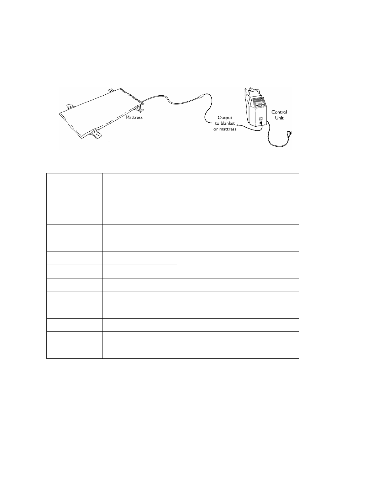
The system is powered and controlled by an electronic control unit. The mattresses and blankets
are powered at low voltage, ensuring safety for patients and operators. The temperature is
controlled automatically to user-selected level. An over-temperature safety cut-out is integrated
into each mattress and blanket.
The control unit is powered from a standard mains supply input and produces a nominal working
output of 24Vac to the mattress or blanket. The system has 4 pre-set operating temperatures of 37,
38, 39 and 40°C and is designed to be operated continuously, maintaining a uniform heat under the
patient.
Patient Warming Systems Page 4 of 25 Rev 1.5; 21-09-07
Page 5
Inditherm Service Manual
PRODUCT RANGE:
Note: Any mattress or blanket can be used with any control unit, but is limited to only one mattress
or blanket per unit.
Model
Size Description
OTM1 1900 x 585 x 40 mm
Operating Room Mattress, Full Length
OTM1-N 1900 x 535 x 40 mm
OTM2 1200 x 585 x 40 mm
Operating Room Mattress, ¾ Length
OTM2-N 1200 x 535 x 40 mm
GTM1 1070 x 585 x 40 mm
Operating Room Gynaecology Mattress
GTM1-N 1070 x 535 x 40 mm
PTM1 560 x 500 x 40 mm Operating Room Paediatric Mattress
OTB1 500 x 1070 x 40 mm Operating Room Blanket
OTB2 500 x 870 x 40 mm Operating Room Blanket
RB1 1660 x 800 x 40 mm Recovery Room Blanket
RB2 1660 x 1200 x 40 mm Recovery Room Blanket
MECU1 160 x 240 x 230 mm Electronic Control Unit
Patient Warming Systems Page 5 of 25 Rev 1.5; 21-09-07
Page 6
Inditherm Service Manual
SYSTEM DESCRIPTION:
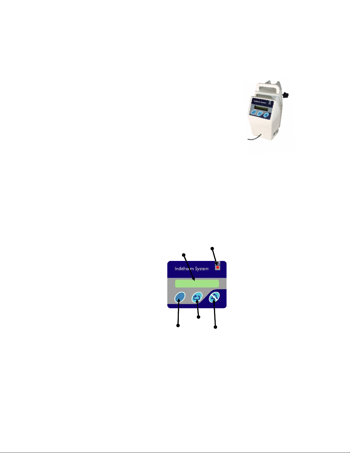
Control Unit
The control unit is a precision temperature controller to be
used in conjunction with an Inditherm warming mattress or
blanket.
The control unit comprises a single case, with integral clamp,
containing mains power inlet, mains fuse, transformer,
control PCB, display and controls.
On the front of the unit is a display and control panel from
which all the functions can be accessed, there are three
control buttons, and an LCD display. A captive cable for
connection to the mattress or blanket is hard wired through
the front face of the unit.
The control unit provides a 24Vac supply to the mattress or blanket and receives temperature
information back. The control unit output is protected by a 1600mA fuse, which is accessible from
the base of the unit. The controller automatically adjusts to the type of mattress or blanket
connected.
The control unit takes signals from the temperature sensor in the mattress or blanket and the
readings are used to control the power output and alert the user to over and under temperature
faults.
Control panel layout is
as shown. For function
of controls, and display
parameters, please see
Operating Instructions
LCD Screen
LCD Screen
Enable Button
Enable Button
Warning Indicator
Warning Indicator
Scroll Button
Scroll Button
Alarm Cancel /
Alarm Cancel /
Reset Button
Reset Button
Patient Warming Systems Page 6 of 25 Rev 1.5; 21-09-07
Page 7
Inditherm Service Manual
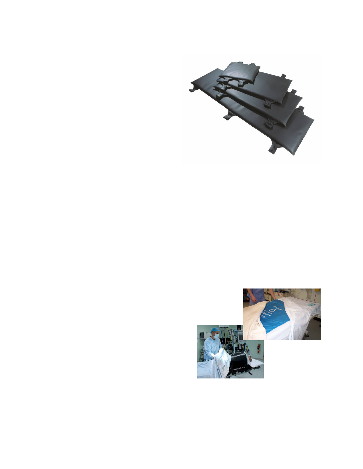
Mattresses
Mattresses are available in various sizes
and are only designed to operate under the
patient. The mattress provides an even
temperature over the whole surface and is
extremely flexible.
The basic construction of the mattresses
remains the same throughout the range.
The mattresses are water and solvent
resistant and have been tested for biocompatibility to allow skin contact during
use. All seams are fully sealed by RF
welding.
The internal patented Inditherm carbon
polymer material provides the heat source,
and internal temperature sensor provides the
output to the control unit for temperature
control. The mattress has a thermal cut-out
that will not allow the mattress to overheat.
A pressure relief pad is integrated into the mattress, underneath the flexible warming surface. This
prevents pressure sores without any attenuation of the warming performance.
Straps are used to retain the mattress in-situ and it is important that the mattress is securely fastened
to the operating table or trolley.
Blankets
Blankets are designed to operate over the
patient. There are two types of blanket
available, one for the operating room and the
other for areas such as recovery room,
intensive care unit, etc. The operating room
blankets are constructed in the same manner as
the mattresses, but without the pressure relief
pad. The recovery blanket has lighter outer
material and stitched seams.
Patient Warming Systems Page 7 of 25 Rev 1.5; 21-09-07
Page 8

Inditherm Service Manual
FAULT FINDING:
General Performance
On initial start up, if the ambient temperature is low, the mattress/blanket will take longer to achieve
the desired temperature. If the desired temperature is not achieved within 40 minutes the alarm will
sound. Should this happen select the reset/alarm button and the unit will restart and the system will
allow another 20 minutes for the desired temperature to be achieved.
The control unit will power the mattress/blanket and monitor temperature performance. Once the
mattress/blanket reaches the desired temperature the control unit will adjust power input to ensure
the desired temperature is maintained. If the maximum allowed temperature is achieved the over
temperature alarm will sound. If the alarm is activated select reset/alarm button and the unit will
restart. An internal safety cut-out temperature management system will ensure the mattress/blanket
will never achieve a temperature greater than 43°C under any fault condition.
When the system is powered on it should follow the cycle below. In case of any error messages or
other faults, refer to the Fault Finding chart.
Display Screen Readout
Bleep will be heard on switch on
Inditherm
V2.03E
English UK
>>>> to change language
Language
English UK
Bleep will be heard
System Check
Bleep will be heard
System OK
Bleep will be heard
Alarm Check
Bleep will be heard
Alarm OK
Bleep will be heard
∧∧∧∧ 37 °C ∧∧∧∧
>>>> 37 °C <<<<
∨∨∨∨ 37 °C ∨∨∨∨
Action Required
None
Option to change Language
See Control Instructions
Bleep will be heard
None Screen Indicates Language
None Automatic system test
None
None Automatic test of alarm sound
None User indication that alarm ok
User can change temperature set
User can change temperature set
User can change temperature set
Information
First screen indicating initialisation
started
For UK users, take no action and
system will automatically continue
User indication that system is OK
Display showing temperature setting.
Arrows will point upwards whilst
heating up to set temperature.
Display showing temperature setting.
Arrows point horizontal to indicate
that set temperature is reached.
Display showing temperature setting.
Arrows will point downwards to
indicate cooling to set temperature.
Patient Warming Systems Page 8 of 25 Rev 1.5; 21-09-07
Page 9

Inditherm Service Manual
Fault Finding / Troubleshooting
Fault or Error Message
General Procedure:
Alarm & Error Message:
“Connect mattress/blanket”
Alarm & Error Message:
“Mattress Fault” (A number will
show after message, this is for
Inditherm indication only)
Diagnostic Checks
• In most cases the fastest fault diagnosis is achieved by carrying out
substitution tests as follows:
- Replace mattress/blanket from faulty system with known working
mattress/blanket
- Replace control unit from faulty system with known working
control unit
- When faulty component is identified, substitute it back and check
it is still not working, then proceed as described in Repair section
• Check mattress is plugged in correctly. Verify that orientation of
plugs/sockets are correct
• Check for any visible damage to cable and connectors
• Unplug connectors and check that pins on plugs show no sign of
being damaged or bent
• If none of the above are applicable call supplier for advice
• Check 6.3A fuse on Control PCB has not blown (see diagram in
Repairs section)
• If fuse is intact, return mattress to supplier
• Ensure none of the control buttons is stuck, by pressing each button
in turn and checking that there is a positive tactile feel and that a
click is heard
Mattress/Blanket warms up but
does not reach temperature set
“Low Temperature Detected”
• Ensure the fault does not only occur when the mattress does not
have a patient on. The system may not reach target temperature if
the mattress is uncovered and the ambient temperature is low
• Place the mattress/blanket on a flat surface that is not cold and
cover upper surface with a standard blanket. Turn on the system
and check that temperature is reached within 15 minutes. If this
works then system is functioning normally and fault is due to local
operating conditions, such as ambient temperature or cold surface
• Reduce set temperature to 37°C, cover mattress with a blanket and
check that temperature is reached within 15 minutes. Increase
temperature setting to required level and check temperature is
reached. If this works then system is functioning normally and
fault is due to local operating conditions, such as ambient
temperature or cold surface
• Run unit in Test mode (see section Testing the System) and check
that the temperature is increasing
• If problems persist, contact supplier and advise operating
conditions, including ambient temperature from Test Mode
Patient Warming Systems Page 9 of 25 Rev 1.5; 21-09-07
Page 10

Inditherm Service Manual
Fault Finding / Troubleshooting
Fault or Error Message
Mattress/Blanket does not warm
up at all
Control Unit display is blank
Diagnostic Checks
• Check control unit is on and there are no error messages
• Disconnect the mattress/blanket from the control unit and check
there is an output of 23Vac ±6% from inside the control unit
between the two black wires (0V & 24Vac) on the transformer
connector to the PCB. (see diagram in Repair section).
• If there is no 23V output, check cable as described in Repair
section.
• If cable is not faulty carry out diagnostic checks as described below
for “Control Unit display is blank”
• Run unit in Test mode (see section Testing the System) and check
that the temperature is increasing.
• If problems persist, contact supplier and advise operating
conditions, including ambient temperature from Test mode
• Check control unit switch is set to On and is illuminated. If switch
not illuminated check fuse in mains plug (if fitted). If fuse not
blown check mains input wiring as described in Repair section
• Check 1600mA external fuse on bottom of unit (see diagram in
Repairs section)
• Check transformer connector is correctly installed onto Control
PCB (see diagram in Repairs section)
• Check output voltage of transformer is 23Vac ±6%. If output is
correct check input to transformer is at mains voltage.
• Check transformer connector is correctly fitted onto Control PCB
• Check ribbon cable connector is correctly fitted onto Control PCB
• Ensure none of the control buttons is stuck, by pressing each button
in turn and checking that there is a positive tactile feel and that a
click is heard
Patient Warming Systems Page 10 of 25 Rev 1.5; 21-09-07
Page 11

Inditherm Service Manual
REPAIRS:
Mattress/Blanket Plug (PS3):
3
Please follow sequence shown for assembling socket
2
once wires have been connected as per Diagram 1.
1
Note: individual cable insulation is numbered.
Front face
Diagram 1: Connections for PS3
Study how the connector is assembled before attempting to replace it. Diagram 3 shows how the
connector parts are assembled.
Each connector has multiple components to it, thus making it imperative that each piece is
correctly put together. Failure to do so may cause damage to the mattress/blanket or control unit.
Due to improvements in design, not all systems are the same. Identify the build type of your system
to ascertain which of these instructions are applicable.
Connector Socket (PS5)
3
Please follow sequence below for assembling socket
once wires have been connected as per Diagram 2.
2
Note: individual cable insulation is numbered.
1
Rear view
Diagram 2: Connections for PS5
Study how the connector is assembled before attempting to replace it. Diagram 4 shows how the
connector parts are assembled.
Each connector has multiple components to it, thus making it imperative that each piece is
correctly put together. Failure to do so may cause damage to the mattress/blanket or control unit.
4
5
6
Rear view
4
5
6
Front face
3
2
1
3
2
1
Patient Warming Systems Page 11 of 25 Rev 1.5; 21-09-07
Page 12

hand tight.
grip up to the plug insert.
cable.
plug to be assembled correctly.
casing.
up to the grey cable grip.
Ensure all the parts are assembled in the
correct order as shown above.
Screw
The cable grip has a locating pin which
should be sat in the top grove of the plug
insert. The keyed part of the plug should
be at the bottom, meaning the locating
pin and screw are in line with each
other. Tighten the screw to grip the
Keyed part of plug
to bottom
Once the insert is inside
the housing, slide the
blue ring down the cable
Screw the collet to the
plug housing until
Inditherm Service Manual
Diagram 3: Assembly for PS3
Once the 5 wires are soldered &
insulated correctly, slide the grey cable
Locating Pin
Slide the grey
washer ring up to
the blue ring.
Tighten up using
the collet spanner.
White Arrows
The screw and the locating pin should
be in line with the white arrows on the
plug housing. Push the plug insert into
the housing until a “click” is heard.
This means it is in place correctly. This
must stay in place for the rest of the
Grey Cable Grip
Screw
Locating Pin
Slide the collet up
to meet the black
The plug is now
complete
Patient Warming Systems Page 12 of 25 Rev 1.5; 21-09-07
Page 13

of the socket is underne
ath.
down the cable.
the grey cable grip.
and screw into housing.
the blue ring.
housing.
Please note correct order of
parts for complete assembly.
Tighten the
screw so the
cable is gripped
tight.
Next slide the grey
washer up to the blue
ring.
Using a multipurpose
silicon lubricant,
lightly spray around
Inditherm Service Manual
Diagram 4: Assembly for PS5
Once the wires
are soldered and
insulated
correctly, slide
the grey piece
Notch
Inlet
Place the socket insert
into the outer shell
housing, fit the housing
so that the small notch
fits into the inlet as
shown.
Ensuring all parts are held
together slide over the collet
Now slide the outer
case over the blue ring
and screw to the front
Screw
Cut out
Ensure the grey cable grip is
pushed up to the socket insert
and that no wires are visible.
Ensure the screw is facing
upwards and the cut out part
Holding all parts together
slide the blue ring up to
Once hand tight use the
collet spanner to tighten.
The socket is now
complete, if required
tighten outer casing with
a suitable sized spanner.
Patient Warming Systems Page 13 of 25 Rev 1.5; 21-09-07
Page 14

Inditherm Service Manual
plate
Control unit repairs
Ensure power is switched off & unplugged before opening the case
Open the case by removing five cross-head
(Pozidriv) screws on underside of case as shown.
Lift upper half of case upwards to separate from
lower half. Remove connector that connects
Case
securing
screws
ribbon cable from Display PCB (located in upper
case half) to Control PCB (in lower case half) at
the left side of the Control PCB. This separates the
upper and lower case halves.
Disconnect
ribbon cable
connector
Note: of the five screws, the top screw as pointed out
above is shorter than the other four and requires a long
nose screw drive (Pozidriv)
Replacing Clamp (MA4):
Clamp
mechanism
When the upper case half has been removed, the
clamp mechanism may simply be lifted out from the
upper case housing. When replacing the upper or
lower case half, the clamp mounting plate must also
be removed.
Replacing Display PCB Assembly (EA4):
Remove the four screws retaining the Display PCB into
the case upper half. Observing anti-static precautions
when handling the circuit board, remove it from the case.
Replace by reversing the above procedure.
Retaining
screws
Replacing Case Upper Half (MA2):
To replace the case upper half, remove clamp, clamp
mounting plate, unscrew handle and Display PCB as
described above, and re-fit components to new case.
Short screw
Case
securing
screws
Clamp
mounting
Patient Warming Systems Page 14 of 25 Rev 1.5; 21-09-07
Page 15

Inditherm Service Manual
Replacing Control Board Output Fuse (FU1):
The output fuse, FU1, can be replaced without removing
the Control PCB from the case lower half. Remove the
fuse from the plastic holder and replace with same rating.
Replacing Control PCB Assembly (EA3):
Disconnect the transformer and the output cable from the
PCB by un-plugging the two connectors. Observing antistatic precautions when handling the circuit board, slide it
upwards in the guide slots to remove it from the case.
Replace by reversing the above procedure.
Replacing Transformer Assembly (TR1):
Disconnect the transformer from the Control PCB by
removing the transformer connector as shown above.
Remove the four retaining screws, noting the position and
orientation of the mounting insulators under the lower rear
side of the transformer for later re-assembly.
Lift the transformer from its mountings and place carefully
beside the case, ensuring there is no strain on the
connecting wires, as shown.
Remove the cable loom plastic spiral binding, after noting
how the cables are retained for later re-assembly.
Remove the transformer input connections from the mains
on/off switch by pulling the crimp connectors off, taking
note of the cable orientation.
Replace by reversing the above procedure, taking care to
ensure connection orientations are correct, the cable loom
binding is replaced and the mounting insulators are
correctly positioned.
Fuse
holder
Transformer
connector
Output cable
connector
Mounting
insulators
Retaining
screws
Mounting
insulators
Mains switch
connections
Patient Warming Systems Page 15 of 25 Rev 1.5; 21-09-07
Page 16

Inditherm Service Manual
Replacing Power On/Off Switch (SW1):
Remove the transformer as described above.
Remove the remaining connections from the mains on/off switch by pulling the crimp connectors
off, taking note of the cable orientation.
Press down and hold the retaining tab on the top of the switch and push the switch outward through
the case.
Replace by reversing the above procedure, taking care to ensure connection orientations are correct.
Replacing Mains Power Cable (EA1):
Remove the transformer as described above.
Remove the input connections from the mains on/off
switch and the fuse holder by pulling the crimp connectors
off, taking note of the cable connections.
Cable
retention
Cable entry
Cut off the crimp terminals and lift the cable from the
retention slots to allow the cable to be pulled out through
the cable entry. Remove the cable.
Pass the new cable through the entry in the bottom of the
case. Strip back the outer insulation and prepare the wires.
Note that the system is double insulated and patient
isolated Type BF, therefore the earth connector is not used
and should be cut off flush with the outer insulation.
Crimp on the terminals and attach them in the same
locations as the removed cable. Pull any excess cable
back through the entry and retain the cable in the slots
provided, as shown.
Fuse holder
Patient Warming Systems Page 16 of 25 Rev 1.5; 21-09-07
Page 17

Inditherm Service Manual
Replacing Control Cable (EA6):
Open the case by removing the 5 screws underneath the control unit
as per Control Unit Repairs Section.
Remove the top half of the case by disconnecting the display
board ribbon cable from the main printed circuit board (PCB).
Remove the transformer by removing the 4 screws as per
Replacing the Transformer Section.
Slide out the PCB and remove it from the bottom half of the
case completely.
Using a pair of sharp side cutters, cut off the end of the hardwire
cable inside the case, so that the plastic housing is removed.
Make sure the plastic housing is discarded as this will be
replaced with a new one accompanied with the hardwire kit.
Patient Warming Systems Page 17 of 25 Rev 1.5; 21-09-07
Page 18

Inditherm Service Manual
Using a pair of long nose pliers, squeeze together the side tabs
on the inside of the plastic insert as shown.
This will enable the insert to “pop” out, thus enabling the rest of
the hardwire cable to be pulled through, and out of the case.
Pull the entire cable out of the case.
Using the new moulded insert from the kit, push into the front
of the case until flush with the front of the case, and the 2
prongs have clicked into position inside the case so it cannot be
pushed out.
Shown on the right is the correct way of how the insert should
look once inserted.
PULL
PUSH
INSERT LEGS IN PLACE
Patient Warming Systems Page 18 of 25 Rev 1.5; 21-09-07
Page 19

Inditherm Service Manual
plate
Once the insert is pushed in correctly, push the new hard wire
cable through the hole and route the wire left, around the
internal fuse as shown.
Each individual core (numbered 1-4 and earth) will need to be
pushed through the hole separately in order for the whole cable
to fit through.
Pull the cable through so that the start of the sheathing can touch
the back of the case.
Holding the plug housing, lip faced down; push the wires in
through the back slots from left to right, numbered 2, 1, 4, 3 and
earth in that order left to right respectively.
Once they are inserted, the one way barb should stop the crimp
being able to be pulled back out. This is fitted correctly.
Slide the PCB back into the case groves and connect the hard
wire plug housing to the board, lip face down.
NB. Make sure the plug housing is lined up correctly with the
pins on the PCB.
Wire 2 should be on HTR1, wire 1 on HTR2, then 4 on NTC1
and 3 on NTC2. The earth wire should be on the RB pin.
The installation of the hard wire kit is now complete.
The unit can be reassembled and tested to make sure that it
works correctly.
Once tested as being correct, screw the unit back together and
place back into service for use.
Replacing Case Lower Half (MA3):
To replace the case lower half, remove transformer,
Control PCB, Power on/off switch, output connector and
mains power cable as described above. Remove fuse
holder and clamp mounting plate and re-fit components to
new case.
Clamp
mounting
Patient Warming Systems Page 19 of 25 Rev 1.5; 21-09-07
Page 20

Inditherm Service Manual
TESTING THE SYSTEM:
Control Unit Tests:
Equipment required:
Inditherm mattress or blanket that is known to be working correctly.
Control cable (units without integral cable only).
Test Procedure:
Inspect the outside of the case, power cable and mains plug for any sign of damage. If any damage
is found, replace parts as appropriate.
With NO mattress or blanket connected, turn on the control unit. Check that the following occur:
• Power switch illuminates
• Display illuminates and a short beep sounds
• Display shows: “INDITHERM Vx.xxn” where “x.xxn” must be “2.03E” or later
• Unit cycles through checks (see Fault Finding section for details)
• Unit halts displaying “Connect Mattress/Blanket”
• Red alarm indicator illuminates
• A constant beep sounds
Connect a mattress or blanket that is known to be working. Check that the following occur:
• Message “Connect Mattress/Blanket” disappears
• Alarm indicator is no longer illuminated
• Continuous beep stops sounding
• Unit completes check cycle (see Fault Finding section for details)
• Display shows last temperature set with ^ to indicate warming up (e.g. ^ 40 C ^)
Press and hold Enable and Scroll buttons together and whilst holding press and release Alarm
Cancel/Reset button. The unit will re-start in Test Mode.
Allow the unit to cycle through the test sequence to the main menu.
Remove the mattress/blanket connector. Check the following occur:
• Unit halts displaying “Connect Mattress/Blanket”
• Red alarm indicator illuminates
• A constant beep sounds
Reconnect the mattress/blanket and check that the following occur:
• Message “Connect Mattress/Blanket” disappears
• Alarm indicator is no longer illuminated
• Continuous beep stops sounding
Patient Warming Systems Page 20 of 25 Rev 1.5; 21-09-07
Page 21

Inditherm Service Manual
Mattress/Blanket Test:
This testing procedure will establish that the mattress/blanket is functioning correctly. It is not
possible for the user to make accurate temperature measurements by any other means than the
procedure below, as these relate to the heating surface itself, which is sealed inside the
mattress/blanket. This accurate heating surface measurement is checked during manufacture and at
any time the mattress is serviced by Inditherm.
Test Procedure:
Press and hold Enable and Scroll buttons together and whilst holding press and release Alarm
Cancel/Reset button. The unit will re-start in Test Mode.
Ensure that Page 1 (Temperature Data) of Test Mode is selected; there are four pages as follows:
• Page 1 Temperature Data (This is the only page relevant for temperature testing)
• Page 2 Bad Data
• Page 3 Rail Data
• Page 4 Safety Timers
To move to the correct page if the unit has not defaulted to Page 1; whilst holding Enable button,
press and hold Scroll button until the page changes, continue until Page 1 Temperature Data is
shown.
Set Temperature
Actual Temperature
To check the actual temperature of the mattress / blanket against the temperature set there will be
two temperatures shown on the screen as follows:
• Top right hand corner is the set temperature
• Bottom right hand corner is the actual temperature of the mattress / blanket
Check that the temperature reading at the bottom right hand corner increases steadily until set
temperature has been achieved with a tolerance of ±1ºC.
Please Note: Whilst in Test Mode, when selecting set temperature, if scroll button is held for too
long the Test Mode page will change to Page 2, if this happens follow instructions above to return
to Page 1. Also when Test Mode is first selected the temperature will default to the lowest within
the range, to change the temperature press and hold enable button and select scroll button in the
normal way.
Patient Warming Systems Page 21 of 25 Rev 1.5; 21-09-07
Page 22

Inditherm Service Manual
System Test:
Connect mattress or blanket to control unit. Turn control unit power switch to On. Check that the
system performs start up checks correctly (see Fault Finding section).
Disconnect mattress or blanket and check error message is displayed and alarm sounds.
Re-connect mattress or blanket and check alarm stops sounding, error message is removed and
display shows temperature setting.
Perform an insulation breakdown and enclosure leakage (touch current) test and ensure results meet
regulation for Class II equipment.
Patient Warming Systems Page 22 of 25 Rev 1.5; 21-09-07
Page 23

Spares - Patient Warming Range
Product Description
Spares for Medical Control Unit & Cable
Case assembly, complete MA1
Case assembly, Top MA2
Case assembly, Bottom MA3
Clamp assembly MA4
Handle assembly MA6
Cable, mains power – United Kingdom EA1 (UK)
Cable, mains power – United States EA1(US)
Cable, mains power - Australia EA1(AU)
Cable, mains power – Japan EA1(JP)
Cable, mains power - Europe EA1(EU)
Inditherm Service Manual
Product
Code
Control cable assembly, complete EA2
Control PCB assembly EA3
Display PCB assembly EA4
Black connector & captive cable, hard wire kit EA6
Black connector for control cable PS5
Fuse Holder, mains power PS8
Power switch SW1
Fuse, T6.3A, control board FU1
Fuse, T1600mA, mains power FU2
Transformer assembly TR1
MECU1 front label LA1
Fuse label LA4
Serial Number / Address / CE label LA5
Power switch label LA6
Spares for Operating Room Warming Mattresses
Connector black plug for mattress PS3
Factory re-cover of OTM1 mattress SV1
Factory re-cover of OTM2 or GTM1 mattress SV2
Factory re-cover of PTM1 mattress SV3
Spares for Operating Room & Recovery Blankets
Connector black plug for blanket PS3
Factory re-cover of RB1 blanket SV4
Patient Warming Systems Page 23 of 25 Rev 1.5; 21-09-07
Page 24

Inditherm Service Manual
label)
EA1(UK)
MA6
EA1(JP)
(Power
EA1(US)
(Power
EA1(AU)
New Zealand)
EA1(EU)
LA
4
(Fuse
LA
6
MA2 (Case assembly, Top)
MA1 (Case assembly, complete)
MA3 (Case assembly, Bottom)
LA1
(Front
(Handle
EA3 (Control PCB assembly)
MA4 (Clamp assembly)
TR1 (Transformer assembly)
EA4 (Display PCB assembly)
(Power
switch label)
PS8 (Fuse holder)
EA6 (Hard wire kit)
SW1 (Power switch)
Cable - UK)
(Power
PS3 (Connector, plug)
PS5 (Connector, socket)
(Power
Cable – USA /
Canada)
Cable - Australia /
Cable - Japan)
(Power)
Cable - Europe)
Patient Warming Systems Page 24 of 25 Rev 1.5; 21-09-07
Page 25

Technical Specification:
Inditherm Service Manual
Mattress Construction:
Temperature Range:
Power: Control Unit:
Mattresses & Blankets:
Dimensions: Control Unit:
Mattresses & Blankets:
Cable Length:
Compliance:
Environmental:
Ambient Temperature (Operating):
Ambient Temperature (Storage):
Relative Humidity:
Inditherm® flexible polymer heating sheet, with 18mm viscoelastic
foam pressure relief pad under and 205g.m-2 expanded polyester
comfort lining over.
Encapsulated in latex-free, nylon fabric cover, with non-microporous
polyurethane coating, fully sealed with RF welded seams.
In-built temperature sensor and over-temperature thermal cut-out.
Connection cable, 20 cm long, with strain relief, fully sealed entry
grommet and IP61 rated waterproof connector.
Sensors and cables let into pressure relief pad for patient comfort.
37°C to 40°C (99°F to 104°F) in steps of 1°C (2°F)
Over-temperature safety cut-out at 43°C (109°F)
230 Vac, ±6%, 50Hz, or 110 Vac, ±6%, 60Hz
75 W
24 Vac (nom.)
25 W to 65 W, depending on size
160 x 240 x 230 mm
Type
OTM1
OTM2
GTM1
PTM1
OTB
RB1
Standard
1900 x 585 x 40 mm
1200 x 585 x 40 mm
1070 x 585 x 40 mm
560 x 500 x 40 mm
1070 x 500 x 40 mm
1660 x 800 x 40 mm
Narrow
1900 x 535 x 40 mm
1200 x 535 x 40 mm
1070 x 535 x 40 mm
Other dimensions available on request
4 m
EN60601-1, Class IIa, Type BF
EN60601-2
93/42/EEC, EEC Medical Devices Directive
73/23/EEC, EEC Low Voltage Devices Directive
15°C to 40°C (59°F to 104°F)
-10°C to 55°C (14°F to 131°F)
30% to 70%
Patient Warming Systems Page 25 of 25 Rev 1.5; 21-09-07
 Loading...