

G
B
All the parts included in this document are the property of Indesit Company S.p.A.
All rights reserved. This document and the information it contains are supplied without liability for possi-
ble errors or omissions; no part of this document can be reproduced, used or copied without written
permission or without being authorised by the terms of a contract clause.
Service Manual
New Electronic Cold Platform 2005
Edition
2005.03.25
Language
English
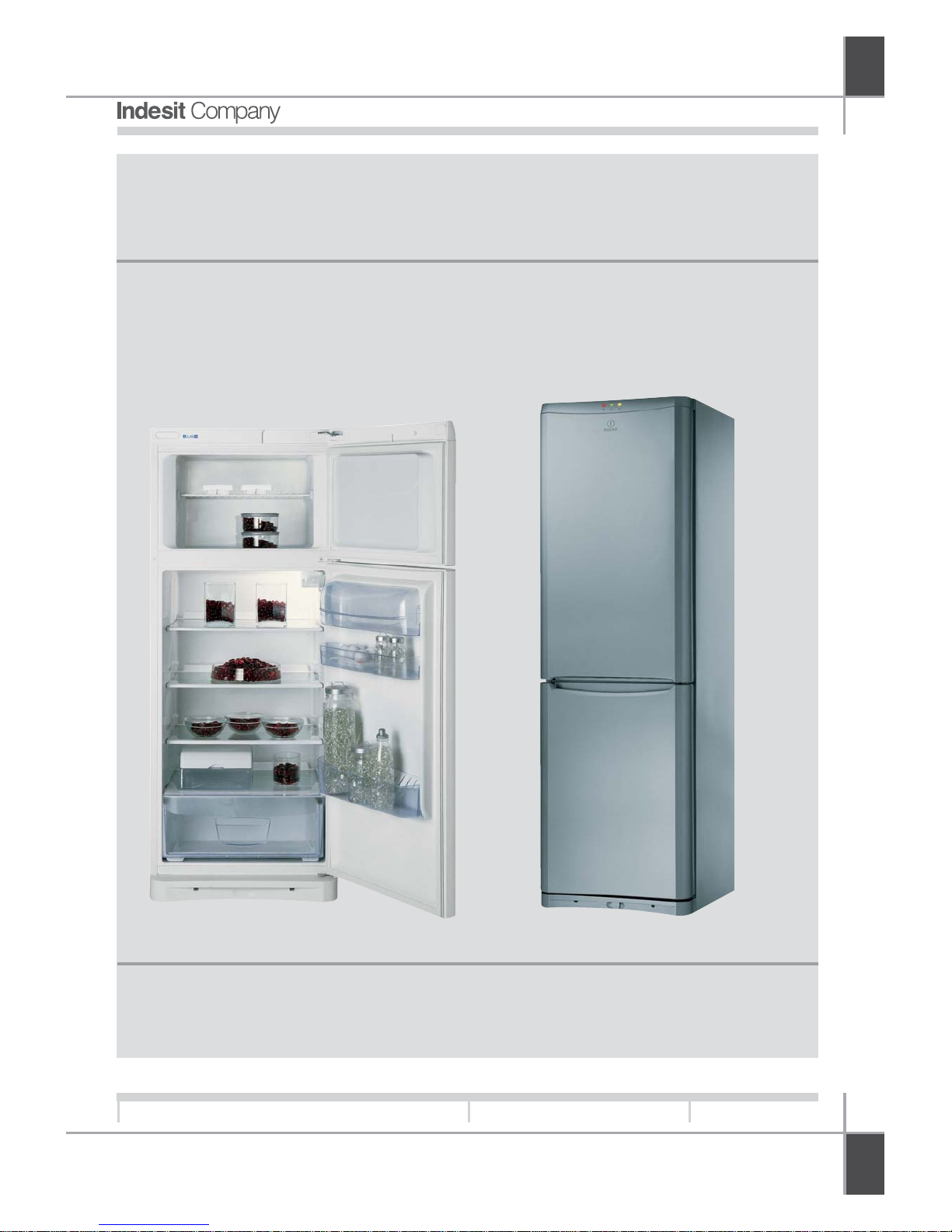
SERVICE MANUAL
New Electronic Cold
Platform 2005.
SERVICE MANUAL
New Electronic Cold
Platform 2005.

G
B
2
Service Manual
New Electronic Cold Platform 2005
Edition
2005.03.25
Language
English
CONTENTS OF THE MANUAL: NOTE FOR THE ENGINEER
This manual is a supporting document for technical personnel. It contains a description of the various
product types, the general operating principle, and indications concerning assistance.
Technical personnel should anyway consult the specific model on
(www.servicenet.indesitcompany.com) to access data and updates of electrical diagrams, techni-
cal bulletins, and spare parts.
G
B
3
Service Manual
New Electronic Cold Platform 2005
Edition
2005.03.25
Language
English
CONTENTS
1. PRODUCT TYPE 4-6
Key 4
nterface 4
Energy Label 6
2. OPERATING LOGIC 7-29
Instructions for settings and operation 7-25
Thermodynamics 26-29
3. COMPONENTS 30-38
4. WIRING DIAGRAMS 39-47
Main PCB circuit diagram 39-41
Sensors diagram 42-46
Freezer wiring diagram 47
5. ASSISTANCE 48-63
Demo Mode 48
Auto Test (Testing / Running-in) 48
Faults and solutions 50-52
Troubleshooting 53
Removing No Frost Electronic Thermostat 54-60
Disassembling the Standard or Evolution Electronic Static Fridge-Freezer 61-63
6. EXPLODED VIEWS 64-72
7. APPENDICES73
Table of Sensors (Temperature / Impedance) 73
Table of Compressors 73
T
YPE
G
B
4
Service Manual
New Electronic Cold Platform 2005
Edition
2005.03.25
Language
English
FRIDGE-FREEZER:
B Bottom freezer
B - A - AA - AAA Efficiency class
N New Platform
1st number 1= 1 compressor
2= 2 compressors
3= 1 compressor + Solenoid Valve or 1 compressor + Electronics
2nd number Height (0 =150, 2 =175, 3 =187, 4 =200)
3rd number only for 4-drawer freezer
4 levels in freezer
V Ventilated (also DGT for electronic models)
T Colour Teak
S Colour Silver
X Colour Stainless Steel
I Isobutane Gas (for classes A , B , C )
NF Full no frost
W Grilles
P Playzone
L Lock
G Graffiti
Final letters (EU,F, etc..) Intended markets
1. PRODUCT TYPE:
1.1. KEY TO INDESIT PRODUCTS:
DOBLE DOOR:
T Top freezer
B - A - AA - AAA Efficiency class
1st number only for NF Type NF ( 1= mechanical , 3= electronic)
number ( 2 - 25 - 3 - 4 ) Height (2 =150, 25 =167, 3 =175, 4 =187)
N New Platform
T Colour Teak
S Colour Silver
X Colour Stainless Steel
I Isobutane Gas (for classes A , B , C )
NF Full no frost
W Grilles
P Playzone
L Lock
V Ventilated
G Graffiti
Final letters (EU,F, etc..) Intended markets
T
YPE
G
B
5
Service Manual
New Electronic Cold Platform 2005
Edition
2005.03.25
Language
English
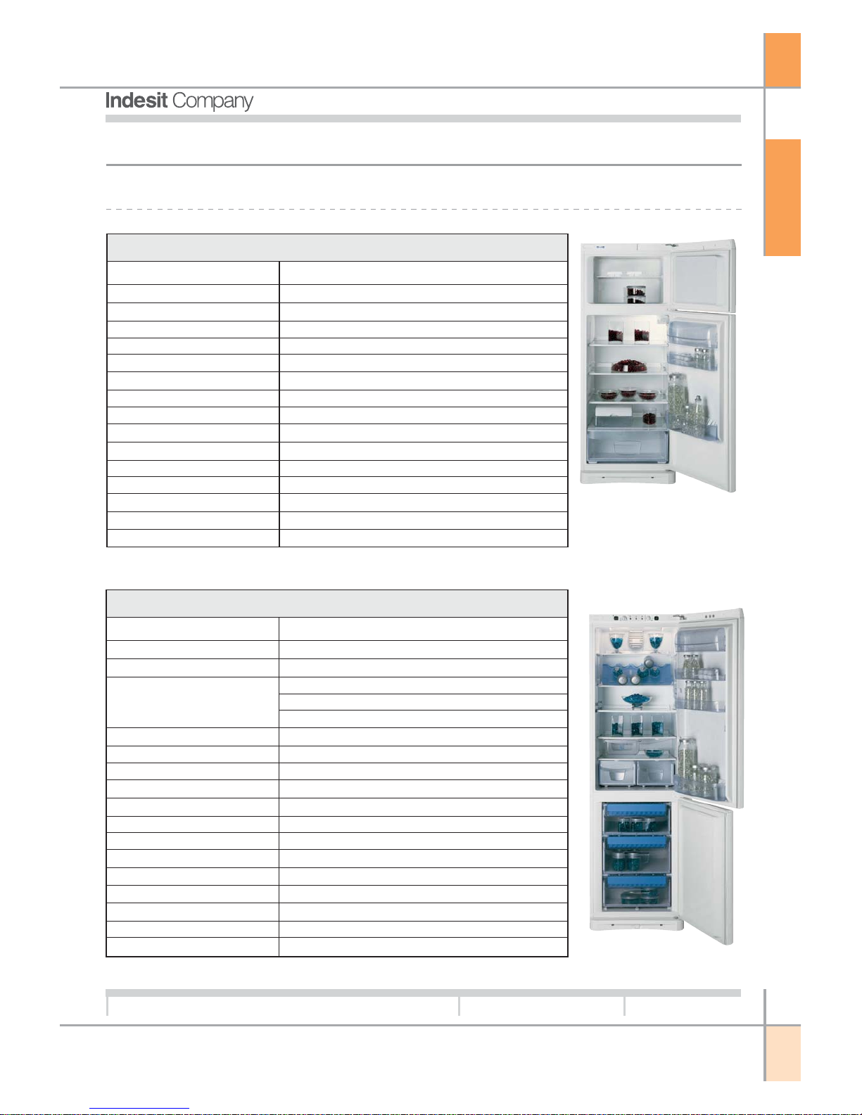
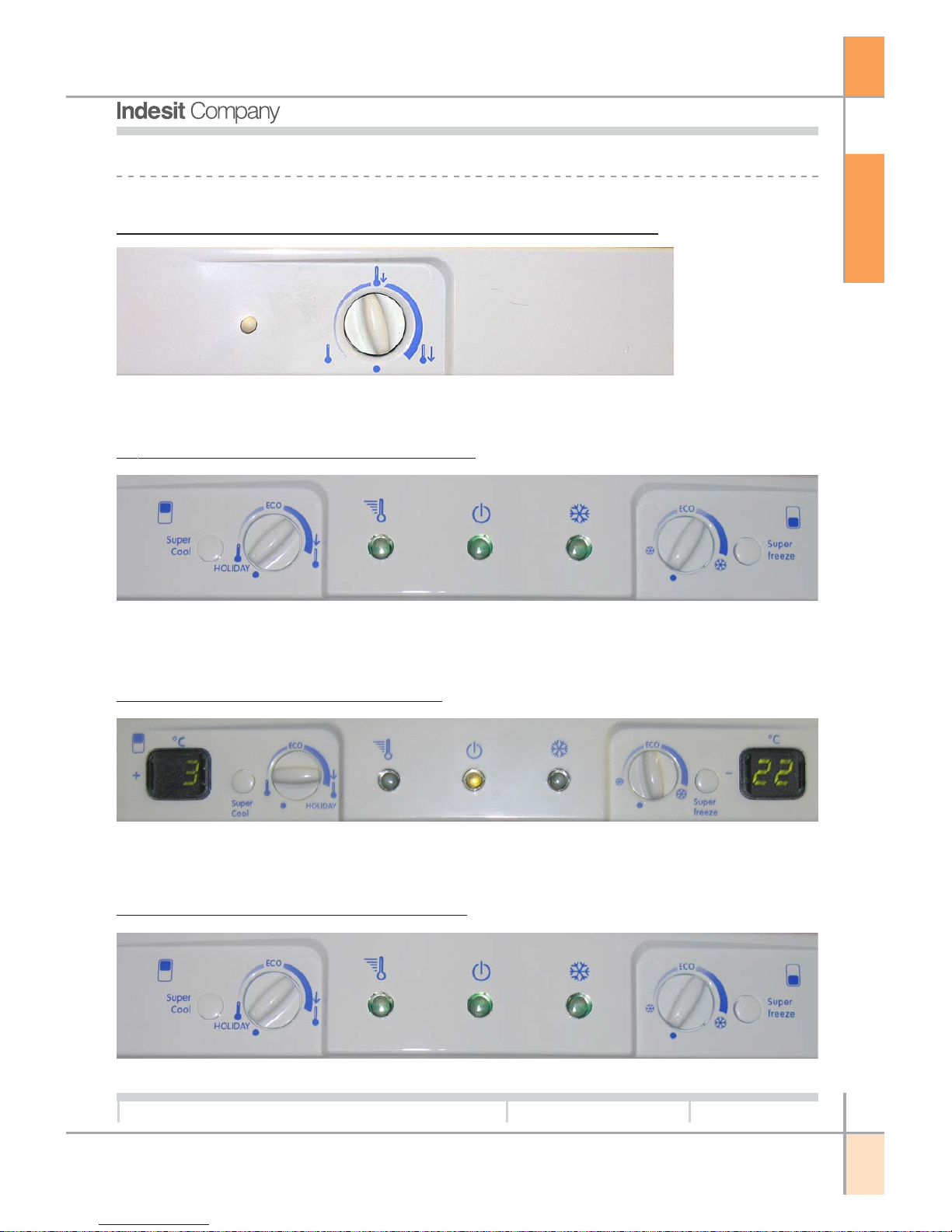
1.2. INTERFACE:
No Frost Fridge-freezer and Electronic Thermostat Double Door.
Basic Electronic Static Fridge-Freezer.
Evolution Electronic Static Fridge-Freezer.
Basic Electronic No Frost Fridge-Freezer.
T
YPE
G
B
6
Service Manual
New Electronic Cold Platform 2005
Edition
2005.03.25
Language
English
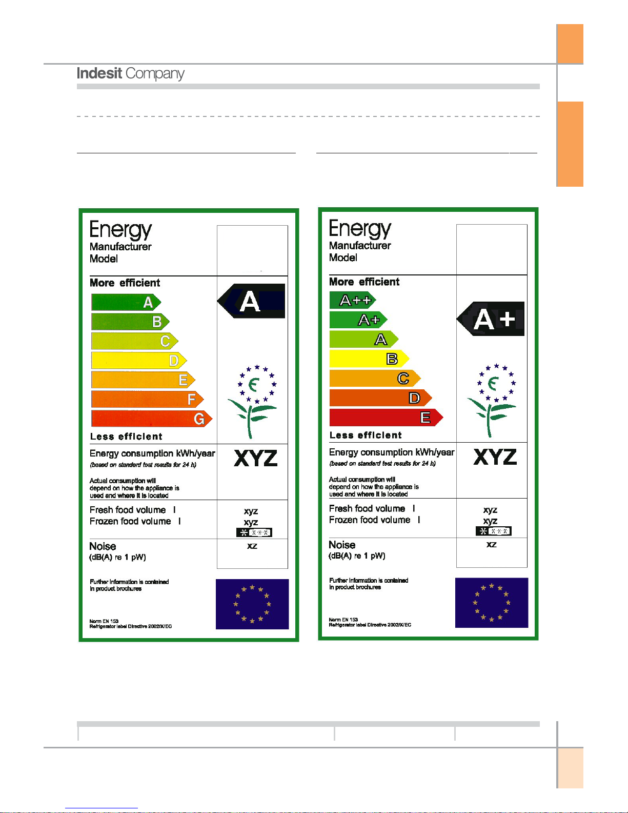
1.3. ENERGY LABEL:
Energy Label for products BAN or TAN:
Class “A” energy label
Energy Label for products BAAN or TAAN:
Class “A+” energy label
Indesit
BAN e TAN
2005
Indesit
BAAN e TAAN
2005
O
PERATION
G
B
7
Service Manual
New Electronic Cold Platform 2005
Edition
2005.03.25
Language
English
2. PRODUCT TYPE:
NO FROST FRIDGE-FREEZER AND ELECTRONIC THERMOSTAT DOUBLE DOOR.
The user interface is located on the fridge cabinet in Fridge-Freezer models and on the freezer
cabinet in Double Door models.
COMPRESSOR OPERATION:
The compressor serves to compress the gas in the
thermodynamic circuit in order to generate the necessary cooling capacity to chill the appliance compartments.
The compressor is managed by the Main PCB with
the aid of a relay and a triac that trips, in parallel
with the relay, only at the time of compressor poweron and power-off to protect the relay from electrical
arcing when the contact is opened and closed. The
compressor
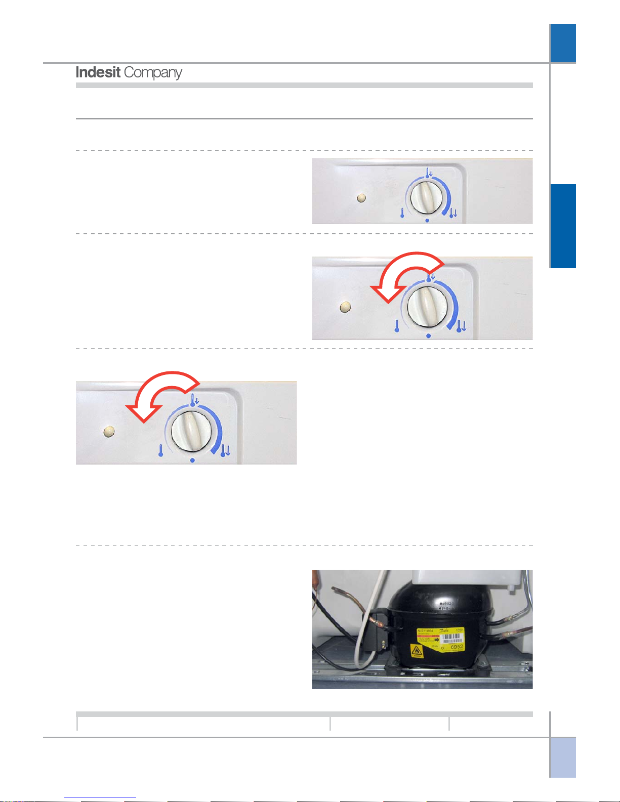
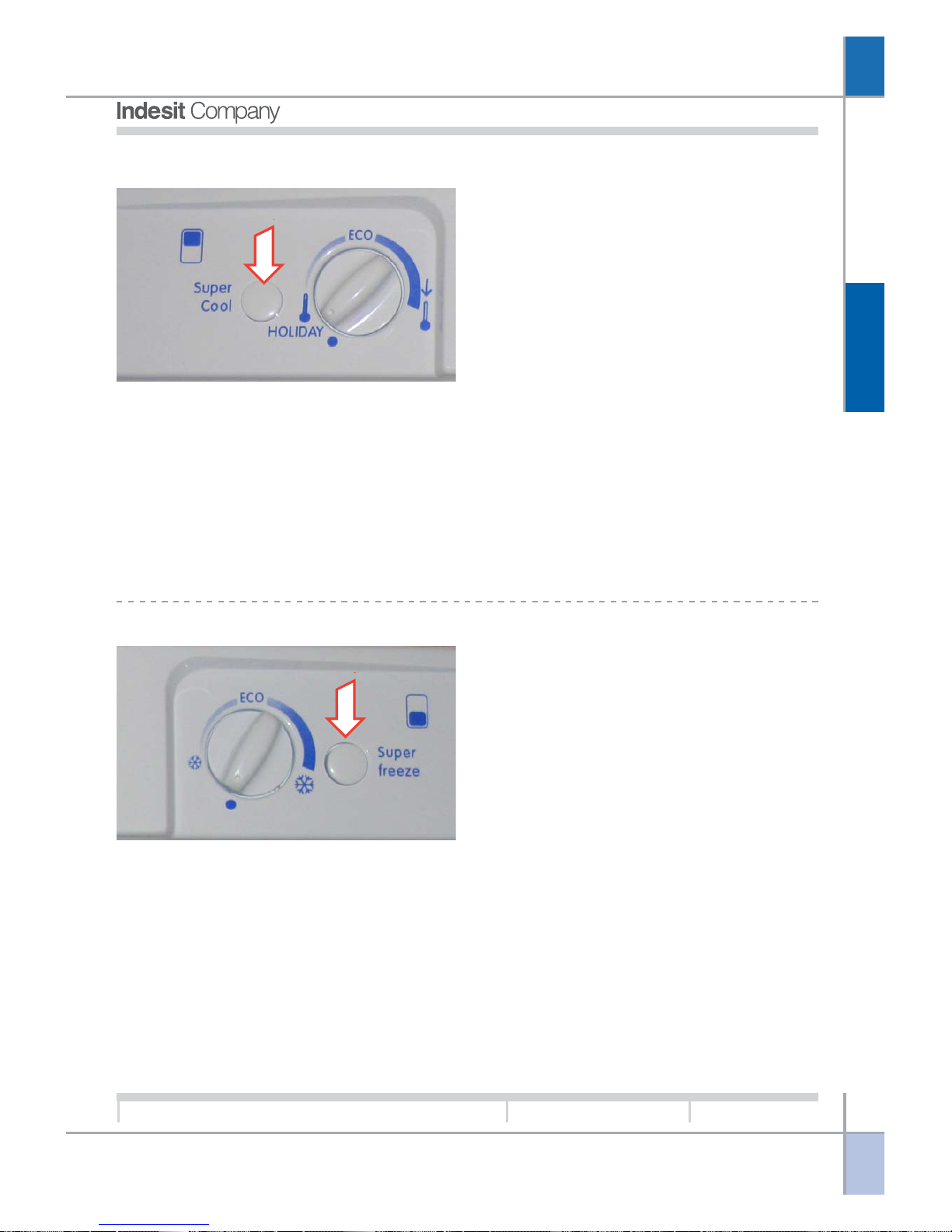
SWITCHING THE APPLIANCE OFF AND ON:
The appliance is switched Off when the knob is set
to Minimum. To switch on the appliance turn the knob
clockwise away from the Minimum position (appliance OFF). Turn the knob counterclockwise to the
Minimum position to switch off the appliance.
TEMPERATURE ADJUSTMENT:
ture. The refrigerator compartment temperature is
controlled by a mechanical damper located on the
multiflow unit. The damper enables cold air from the
evaporator coil to cool the refrigerator compartment.
Temperature adjustment is performed in accordance
with specific rules if the following conditions occur:
• Temperature detected by PCB sensor (on the
board) is between two values parameterised in
the EEPROM memory;
• The time that has elapsed from the last time the
door was opened is greater than the relative parameter stored in the EEPROM memory;
• The compressor power-on time is lower than the
parameter stored in the EEPROM;
The freezer compartment temperature is adjusted
by the electronic PCB. To set a lower temperature
turn the knob clockwise, turning the knob
counterclockwise gives a higher temperature. The
refrigerator compartment temperature depends on
the adjustment of the freezer compartment tempera-
O
PERATION
G
B
8
Service Manual
New Electronic Cold Platform 2005
Edition
2005.03.25
Language
English
OFF
ON
Ventola Freezer
Compressore
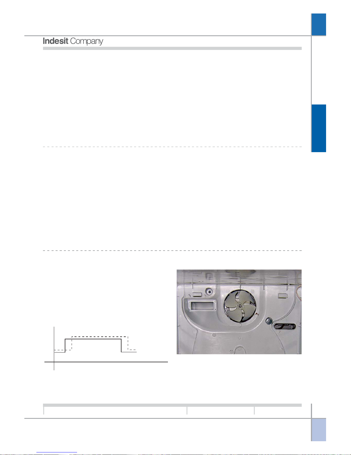
FREEZER FAN OPERATION:
The freezer van is located in front of the evaporator
coil and is designed to distribute the cold air produced by the evaporator coil uniformly inside the
freezer compartment.
The freezer fan is managed by the PCB and is
switched on/off after a preset time interval that is
parameterised in the EEPROM after a compressor
start/stop.
The defrost procedure is preceded by activation of
the fan for a time interval that is parameterised in
the EEPROM memory.
switches on whenever a demand for cooling is received.
There are situations of cooling demand in which the
compressor remains off. These are as follows:
1. Compressor protection: the compressor switches
on once a minimum safety time lag has elapsed
since the last power-off, thereby allowing gas
pressure to reach a point of equilibrium in the
refrigerant circuit. The same minimum safety time
is observed in the event of a mains power interruption (voluntary or involuntary). This compressor protection strategy is observed only after the
product has been operating continuously for the
number of hours defined in the EEPROM memory.
This facilitates the execution of factory tests.
2. Long periods of activity: if the compressor remains
on for more than a value set in EEPROM memory
it is switched off, even in the presence of a cooling demand.
3. Pause after defrost: at the end of the defrost cycle the compressor observes a protection time
parameterised in the EEPROM so that the water
formed during the defrost can be completely
drained.
DEFROST AND DRIP TRAY HEATING ELEMENTS:
There are two defrost heating elements connected
in parallel and controlled by the Main PCB:
The defrost heating element, which serves to melt
any ice that has formed on the evaporator coil that
could have a negative effect on the thermal exchange
between the evaporator and surrounding air.
The drip tray heating element, which is designed to
melt any ice that detaches from the evaporator.
In addition, the drip tray heating element prevents
blockage of the pipe that transfers the water from
the drip tray to the drain tube.
During the defrost cycle the compressor is switched
off, even in the presence of a cooling demand from
the freezer compartment. The heating elements are
switched off by means of a thermal protection (closed
when the appliance is cold and open when it is hot).
The parameters utilised to start the defrost cycle are
as follows:
1. Compressor ON time since last defrost cycle.
2. Duration of last defrost cycle; if the duration of
the last defrost cycle was short, the next defrost
cycle will be longer, and vice versa.
3. Duration of doors open condition.
After the defrost cycle the fan starts after a time interval following a compressor start, also this interval
is parameterised in the EEPROM memory;
thi}Ëinterval is different from the interval programmed
for normal operating conditions.
O
PERATION
G
B
9
Service Manual
New Electronic Cold Platform 2005
Edition
2005.03.25
Language
English
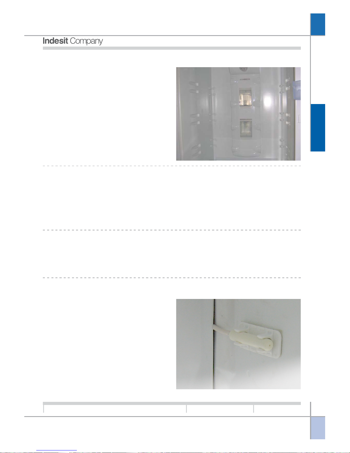
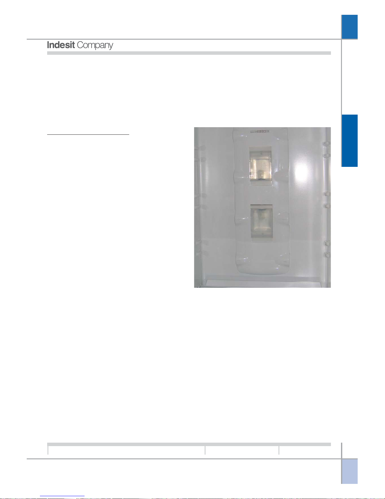
FRIDGE LAMP OPERATION:
FAULT MANAGEMENT:
The refrigerator lamp is located inside the multiflow
unit. The Fridge-Freezer appliance has one lamp
while the Double Door appliance has two lamps. The
lamps are controlled by a triac on the PCB, and
switch on when the fridge door is open (assuming
the appliance is switched on). If the door remains
open for a time period that is greater than the time
interval stored in the EEPROM memory, the lamp
will start flashing and continue until the door is
closed.
The appliance is designed to recognise faults, specifically those relative to the temperature sensors and the
EEPROM memory.
For faults of this type there are various alternative operating modes that can be activated to allow the
appliance to continue to function normally.
Normal operation of the appliance will resume after mains power has been disconnected and reconnected
(if the problem persists the appliance will resume alternative mode operation).
FRIDGE DOOR OPEN:
If the door remains open for a prolonged time period the fridge lamp flashes at regular intervals. Close the
door to reset the alarm.
FREEZER AIR SENSOR FAULT:
In the event of a fault of the freezer air sensor, the
appliance will no longer be able to execute thermostatic control with the parameters set in the EEPROM
memory.
The appliance will continue to function controlled by
the main PCB, which assumes timer control of operation in accordance with the temperature set by
the user and parameters stored in the EEPROM
memory.
O
PERATION
G
B
10
Service Manual
New Electronic Cold Platform 2005
Edition
2005.03.25
Language
English
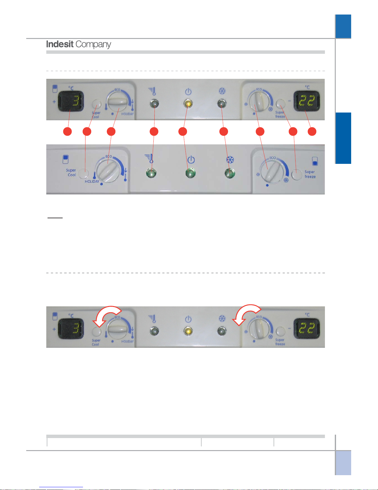
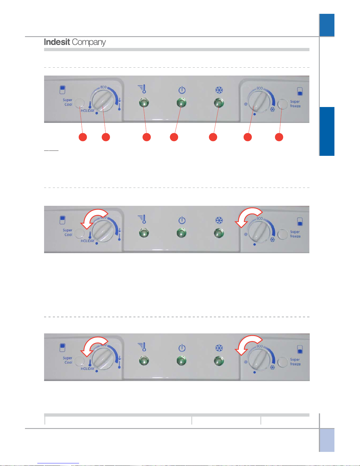
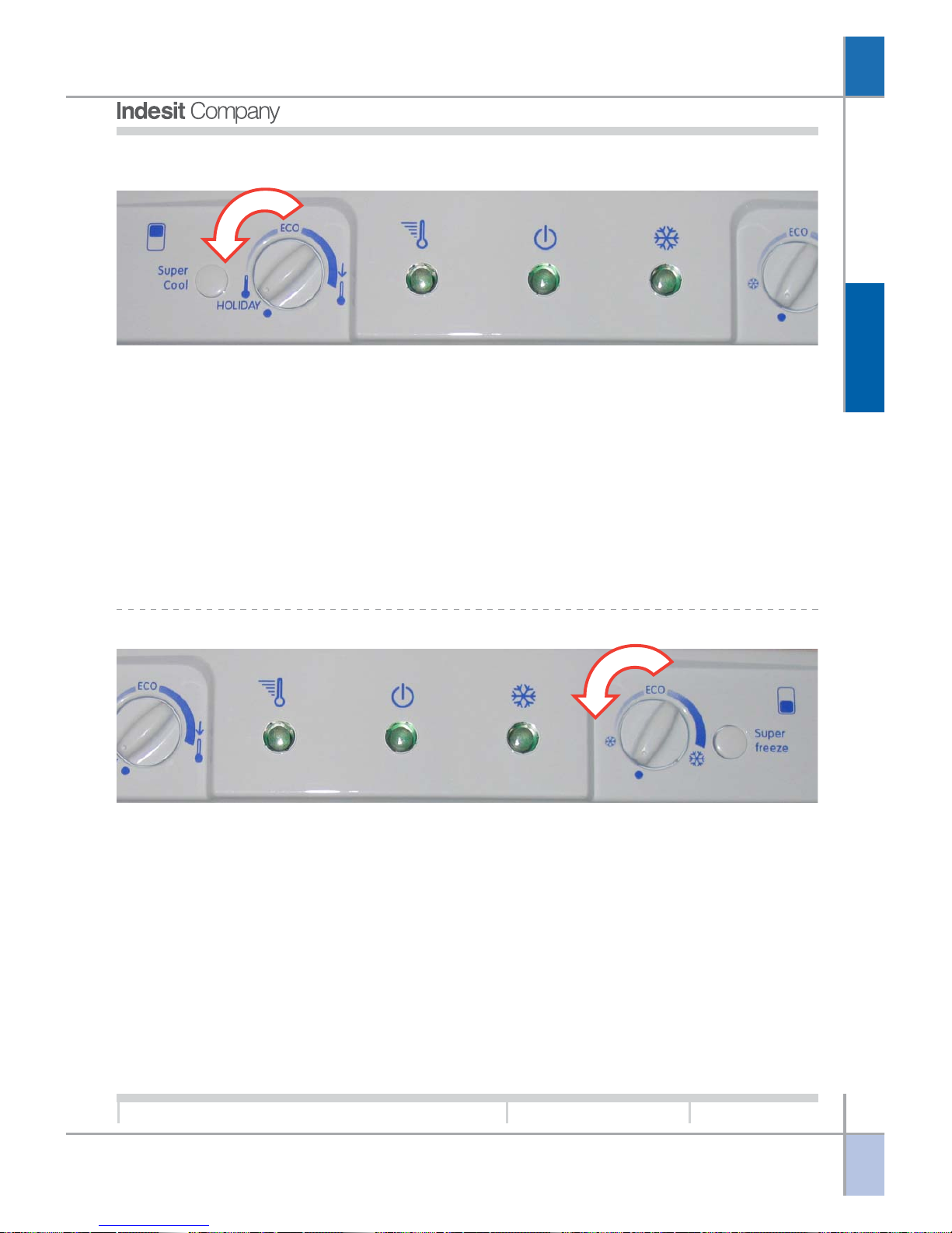
BASIC ELECTRONIC STATIC FRIDGE-FREEZER AND EVOLUTION MODEL.
Key:
1. SUPER FRIDGE button.
2. FRIDGE knob.
3. SUPER FRIDGE LED.
4. Power indicator LED.
5. SUPER FREEZER LED.
6. FREEZER knob.
7. SUPER FREEZER button.
8. FRIDGE temperature display. (7-segment)
9. FREEZER temperature display. (7-segment)
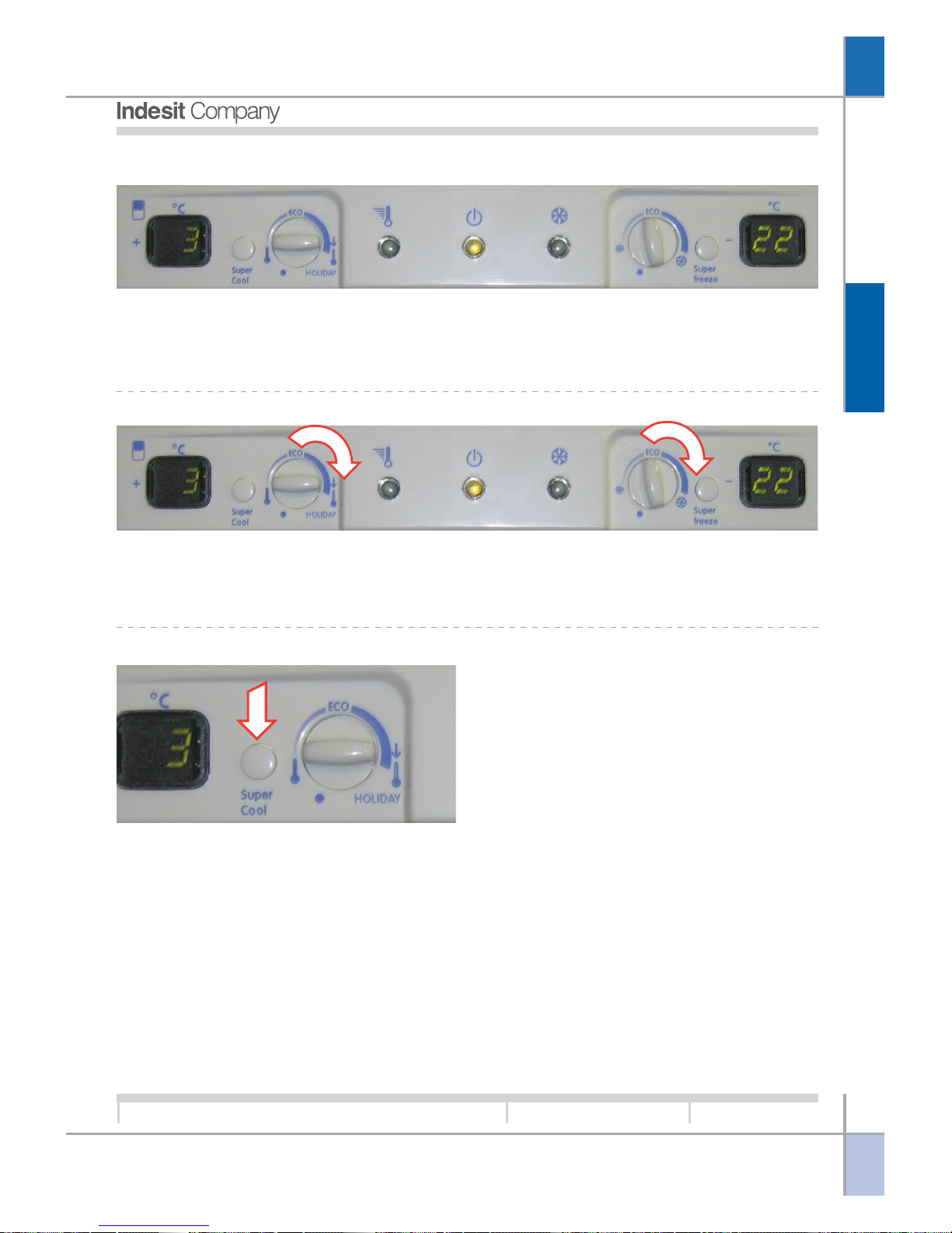
SWITCHING THE APPLIANCE OFF AND ON:
The appliance is Off when the freezer compartment
knob (6) is set to Minimum.
To switch the appliance on turn the freezer knob
clockwise, away from the Minimum position.
To switch it off turn the knob counterclockwise to the
Minimum position. All active functions are deactivated when the appliance is switched off. If the appliance is On and the refrigerator compartment knob
(2) is set to minimum, the refrigerator compartment
is Off.
To switch on the refrigerator compartment, turn the
knob clockwise away from the Minimum position; to
switch it off turn the knob counterclockwise to the
Minimum position. If the SUPER COOL function is
active it will be automatically deactivated by switching the refrigerator compartment off.
1 2 3 4 5 6 78 9
O
PERATION
G
B
11
Service Manual
New Electronic Cold Platform 2005
Edition
2005.03.25
Language
English
TEMPERATURE SETTING:
Turn the refrigerator knob (2) or freezer knob (6)
clockwise to decrease the temperature or
counterclockwise to increase the temperature until
reaching the minimum position; when the refrigera-
tor knob is set to minimum the refrigerator compartment will be switched off, while setting the freezer
knob to minimum switches off the entire appliance.
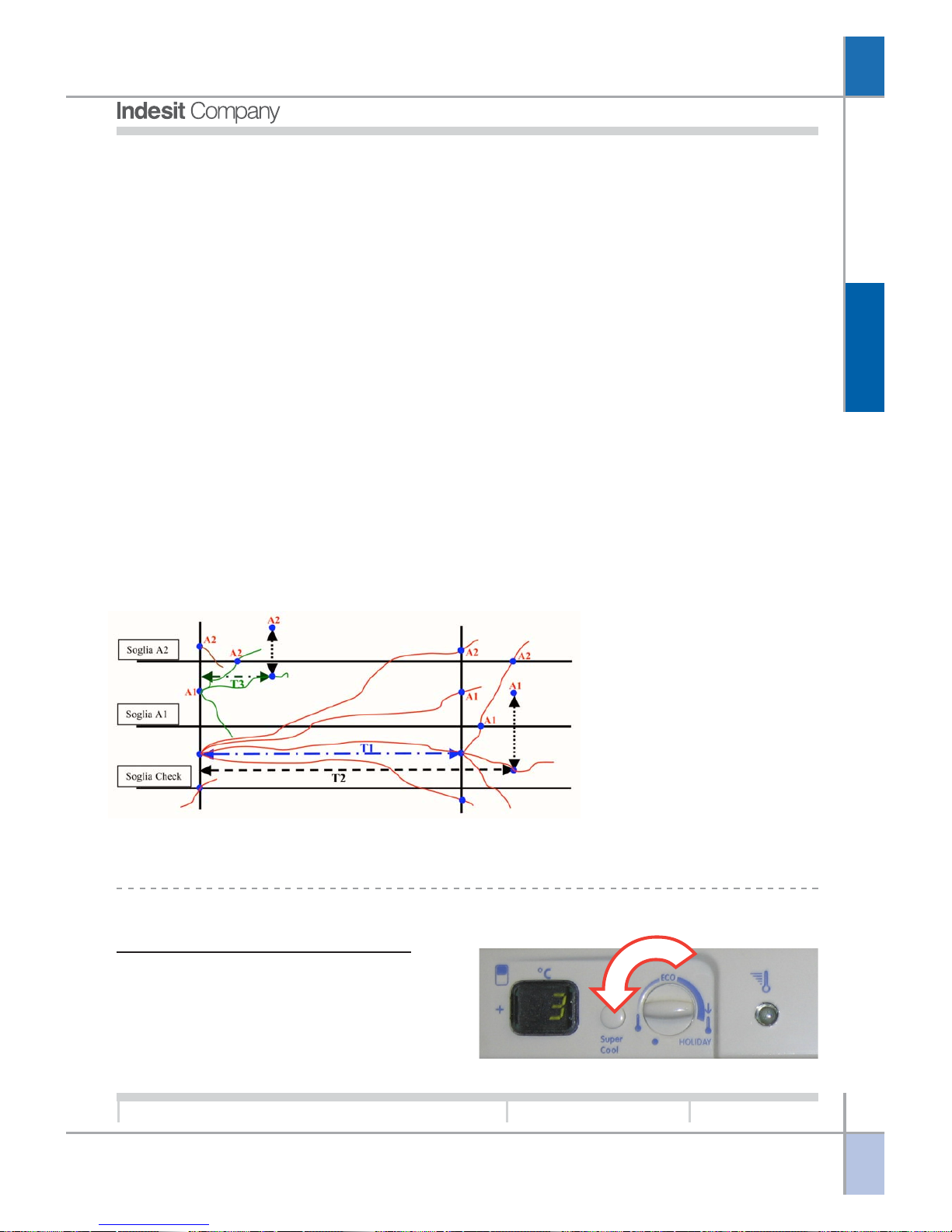
“SUPER COOL” FUNCTION:
TEMPERATURE DISPLAYS (7–SEGMENT):
The displays serve to show the user temperature
setting for the refrigerator compartment and the
freezer compartment in accordance with the position of the knob. Freezer compartment temperature
is from -18°C to -26°C, while refrigerator compartment temperature is from +3°C to +8°C. If either the
refrigerator or freezer is switched off, the display (7–
segment) will remain blank.
This function allows optimal chilling of large quantities of food in the refrigerator compartment by altering the refrigerator On and Off set-points in accordance with parameters stored in the EEPROM
memory.
Activating this function forces the fridge fan, which
starts after a time parameterised in the EEPROM
memory, to run continuously to obtain the maximum
cooling capacity in the refrigerator compartment. The
SUPER COOL function cannot be activated if either
of the two freezer temperature alarm conditions is
active. Activation of an alarm mode or switching off
the appliance or only the refrigerator compartment
automatically causes this function to be deactivated.
Press button (1) to activate the function. In the case
of the basic interface LED (3) will illuminate confirming activation of the function. Deactivation of the
SUPER COOL function can be performed by the
user pressing the relative button again, or will occur
automatically at the end of the procedure (number
of cycles) as defined in the EEPROM memory.
If the appliance is equipped with the Digit interface,
the relative 7-segment display will show temperature 1 until deactivation of the function, at which point
the display will return to the temperature value set
on the freezer knob. The user can also activate the
ECO or HOLIDAY functions, which will become operational as soon as the SUPER COOL function has
been deactivated The SUPER COOL function cannot be selected if the HOLIDAY function is active. In
case of electrical power failures the function is resumed automatically when power is restored, completing the remaining cycles except in the presence
of a temperature alarm
O
PERATION
G
B
12
Service Manual
New Electronic Cold Platform 2005
Edition
2005.03.25
Language
English
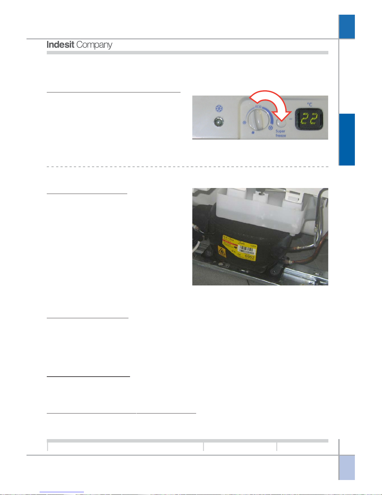
This function provides optimal freezing of food in the
freezer compartment, conserving properties of texture and flavour.
Activating this function forces the compressor run
continuously thereby obtaining maximum freezing
power in the freezer compartment.
There are two modes: SUPER FREEZE 24h, which
is used for freezing small quantities of food (this function should ideally be activated immediately before
before placing the food in the compartment).
The SUPER FREEZE function is activated by pressing button (7); this will cause LED (5) to illuminate to
confirm that the function is active. The second mode
is SUPER FREEZE 48h, which is activated by holding down button (7); this function is used for freez-
ing large quantities of food (should be activated 24h
before placing the food in the compartment). In this
case LED (5) will flash for the first 24 h and then
remain steadily illuminated for the second 24 h period. If the appliance is equipped with the Digit inter-
face, the temperature of -35 °C will be displayed on
the 7-segment display until the function is deactivated, at which point the LED will extinguish and the
value set on the freezer knob will be shown on the
display.
The function cannot be activated in the presence of
alarm signals. Activation of an alarm mode or switching off the appliance automatically causes this function to be deactivated. This mode can be deactivated
by pressing the relative button again. The function is
deactivated automatically when the maximum time
has elapsed (24 or 48 hours) or, in the case of 24 h
mode, once a given temperature has been reached
and maintained for a time interval parameterised in
the EEPROM memory.
The ECO or HOLIDAY functions can be selected,
although they will only become operational when the
SUPER FREEZER function has terminated.
In case of electrical power failures the function will
be reactivated automatically when power is restored,
completing the remaining hours, unless a temperature alarm occurs in this interval.
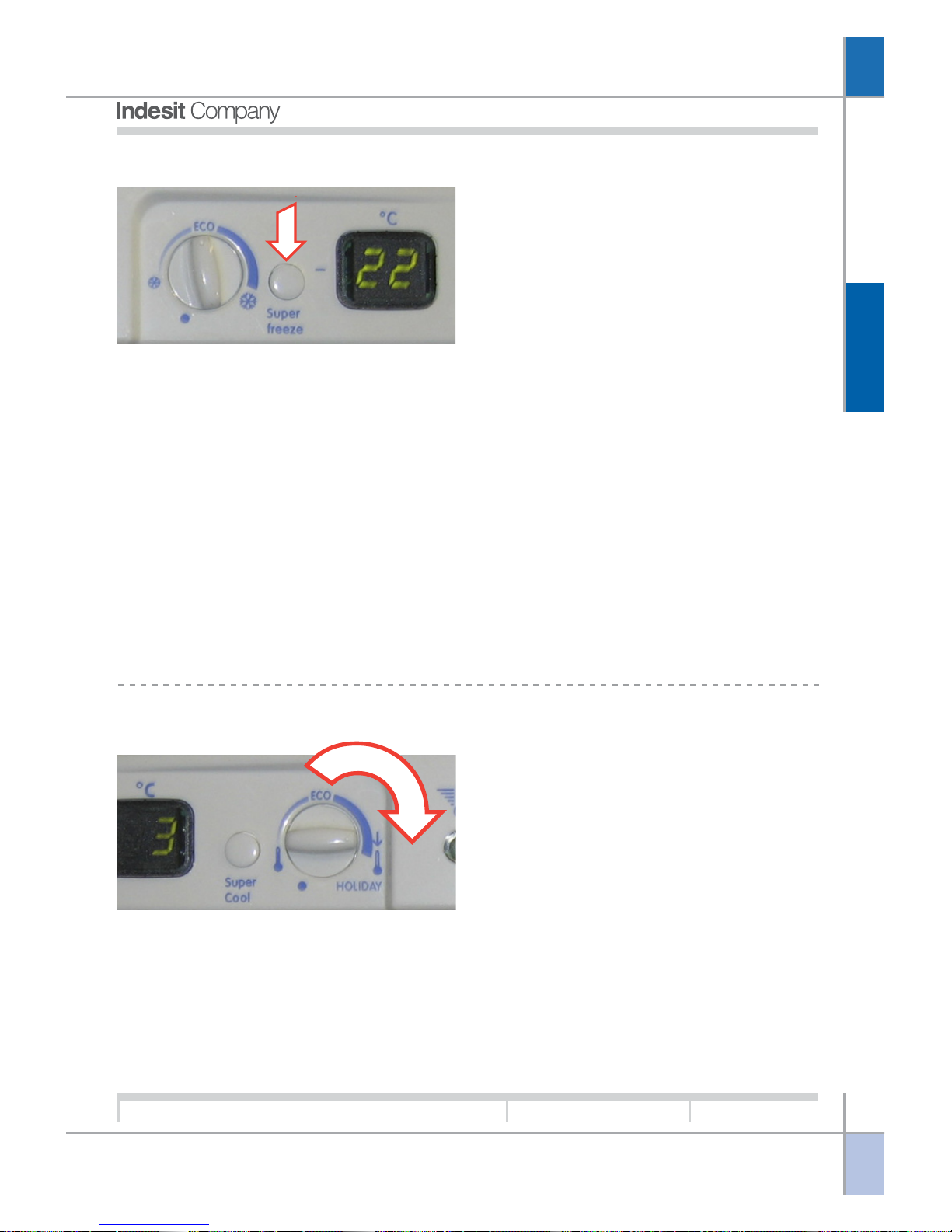
SUPER FREEZER FUNCTION:
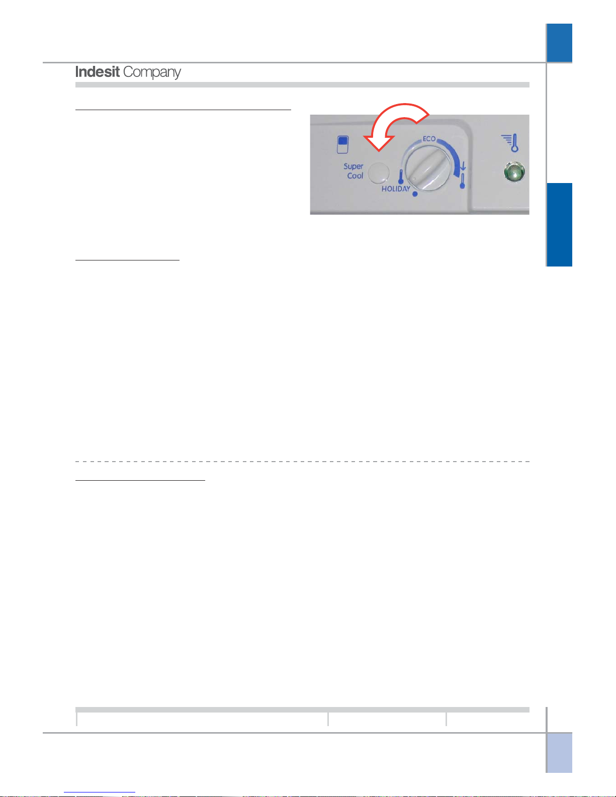
HOLIDAY FUNCTION:
In case of minimum use of the refrigerator compartment this function makes it possible to store food
while reducing power consumption to the minimum
(E.g. during holiday periods the freezer can remain
full and the refrigerator empty). The function is activated by turning the refrigerator knob (2) to the
HOLIDAY setting (a double beep will sound to indi-
cate that the function is active). To deactivate the
function move the knob away from the HOLIDAY
position (the appliance will emit a single beep) or
switch off the refrigerator compartment or the entire
appliance. The HOLIDAY function cannot be activated when alarms are present. Since the two functions are not compatible it is not possible to select
the SUPER COOL or SUPER FREEZER functions
if the knob is set to HOLIDAY. If these two functions
are already active when the HOLIDAY function is
selected, SUPER COOL and SUPER FREEZER will
be terminated normally, after which the HOLIDAY
function will start. If one or more of the sensors is
faulty, the function will be controlled by the main PCB
utilising alternative parameters. In case of electrical
power failures the function will be reactivated automatically when power is restored.
O
PERATION
G
B
13
Service Manual
New Electronic Cold Platform 2005
Edition
2005.03.25
Language
English
ECO FUNCTION:
ALARMS MANAGEMENT:
Alarms serve to notify the user of specific conditions such as: prolonged opening of fridge door; excessively
high temperature in freezer compartment.
Door Open Alarm:
If the fridge door is kept open for a time longer than that defined by a parameter set in EEPROM memory,
an audible signal is emitted and the fridge lamp flashes at regular intervals. Close the door to reset the
alarm.
Freezer Compartment Temperature Alarm:
There are two types of alarms that can be generated if the freezer compartment temperature rises excessively:
Alarm A1:
In this case it is still possible to recover the food in the freezer by cooking it immediately and either consuming it or re-freezing it once cooked.
LEDs 3 and 5 flash on the appliance control panel to indicate the presence of the alarm (if the refrigerator
is equipped with the Digit interface the message A1 is displayed on the freezer temperature display).
Alarm A2:
In this case the food in the freezer compartment must be discarded. LEDs 3, 4 and 5 flash on the appliance
control panel to indicate the presence of the alarm (if the refrigerator is equipped with the Digit interface the
message A2 is displayed on the freezer temperature display).
At the same time an audible signal is emitted by the beeper during both alarm modes.
This function allows storage of food with the lowest
possible power consumption while ensuring excellent results. The ECO function can be activated by
turning the refrigerator (2) and freezer (6) knobs to
the ECO setting. To deactivate the function simply
turn one of the two knobs away from the ECO setting. The compressor starts in the presence of a
cooling demand from either of the two compartments.
To optimise operation of the appliance there is a fixed
time setting for operation of the freezer at the end of
a refrigerator cooling demand by means of a switch
over of the relative solenoid valve without having to
disconnect the compressor.
Normally, the ECO function adjustment corresponds
to the adjustment utilised to calculate power consumption in compliance with European regulations.
The function cannot be activated in the presence of
alarm signals.
The SUPER FREEZER and SUPER FRIDGE functions can be activated when the ECO function is set.
These functions will assume priority over the ECO
function. The appliance returns to ECO function
mode once the conditions are met to deactivate the
priority procedure. If one or more of the sensors is
faulty, the appliance will be controlled by the main
PCB utilising alternative parameters. In case of electrical power failures the function will be reactivated
automatically when power is restored.
O
PERATION
G
B
14
Service Manual
New Electronic Cold Platform 2005
Edition
2005.03.25
Language
English
In alarm status the appliance forces operation utilising specific On / Off parameters that control the temperature in the freezer compartment at specific values depending on the type of alarm. To reset the alarm
and restore normal operation, the appliance must be set to LOGICAL OFF (freezer knob set to minimum).
Control of freezer compartment temperature is continuous during operation of the appliance, by means of
the freezer air temperature sensor; this control will proceed even if the appliance is in one of the two
available alarm conditions. In the event of a freezer air sensor fault, the alarms will no longer be displayed.
Temperature control is not performed for a time parameterised in the EEPROM memory to prevent false
alarms both during the testing process and at the time of power-on immediately after the appliance has
been purchased.
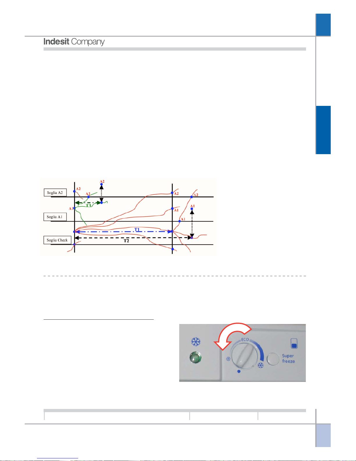
Temperature control and alarm signalling are managed by means of three thresholds: Check Threshold
(the control strategy becomes more intensive when this threshold is exceeded); Threshold A1: when exceeded, alarm A1 is activated; Threshold A2: when exceeded, alarm A2 is activated. The values of the three
thresholds are parameterised in the EEPROM memory.
If the control temperature exceeds the Check Threshold but does not exceed the A1 Alarm threshold, a
delay time T1 is activated (parameterised in the EEPROM) before performing the next control, to prevent
the generation of alarm signals when the placement of large quantities of warm food in the freezer compartment near the freezer air sensor causes unreliable transient temperature readings. At the same time another time interval T2 is activated (parameterised on the EEPROM) after which, if the temperature is constantly maintained between the Check Threshold and the Alarm A1 Threshold, alarm A1 is forced because
the persistence of a temperature in this range for this period of time is anyway a symptom of faulty operation
and constitutes a risk for the correct preservation of the food.
At the time of activation of alarm A1 also a time interval T3 is activated (parameterised in the EEPROM)
after which, if an alarm reset has not been executed, alarm A2 is forced, since in the situation of alarm A1
the freezer compartment is set to a temperature that may not be the same as the temperature selected by
the user. This time interval is reset also when power is restored after a mains power failure.
THERMOSTAT CONTROL.
The temperature adjustments in both the compartments are independent from each other and set individually by the relative knobs.
Freezer Compartment Adjustment:
8°C
-6°C
2°C
T1 = 2 1/2 Hours
T2 = 24 Hours
T1 = 120 Hours
N. B.: The time and temperature values shown in this graph are EEPROM parameters and as such they are subject to modification
Freezer temperature is managed by the PCB utilising
the value detected by the freezer air sensor to switch
the compressor on/off.
The On / Off threshold is detected by the EEPROM
and it depends on the user setting.on the interface.
O
PERATION
G
B
15
Service Manual
New Electronic Cold Platform 2005
Edition
2005.03.25
Language
English
Compressor Operation:
The compressor serves to compress the gas in the
thermodynamic circuit in order to generate the necessary cooling capacity to chill the appliance compartments.
The compressor is managed by the Main PCB with
the aid of a relay and a triac that trips, in parallel with
the relay, only at the time of compressor power-on
and power-off to protect the relay from electrical arcing when the contact is opened and closed, otherwise the compressor is powered exclusively via the
relay when it is running.
The compressor is started whenever a cooling demand is received.
In certain conditions the compressor will remain stopped despite the presence cooling demands; these
situations are as follows:
Compressor protection:
The compressor switches on once a minimum safety time interval (parameterised in the EEPROM) has
elapsed since the last power off, thereby allowing the pressure of gas to reach a point of equilibrium in the
refrigerant circuit. The same minimum safety time is observed in the event of a mains power interruption
(voluntary or involuntary). This compressor protection strategy is observed only after the product has been
operating continuously for a number of hours defined in the memory. This facilitates the execution of factory
tests.
Long periods of activity:
If the compressor runs for a time greater than a value defined in the EEPROM memory, it is switched off
even in the presence of a cooling demand from either or both compartments. This feature is designed to
protect the compressor.
Fridge Fan Operation: (only in Digit models)
The fan is designed to distribute cold air uniformly inside the fridge compartment. The fan is controlled by
If the temperature measured by the freezer air sensor is above the On threshold a cooling demand is
activated thereby starting the compressor; on the contrary, if the freezer air sensor detects a temperature
lower than the Off temperature, the cooling demand is deactivated.
Refrigerator Compartment Adjustment:
Refrigerator temperature control is managed by the
PCB according to the temperature measured by the
refrigerator air sensor in relation to the user settings
on the interface.
If the temperature measured by the refrigerator air
sensor is above the On threshold, a cooling demand
is activated thereby starting the compressor and the refrigerator fan (if present); on the contrary, if the
refrigerator air sensor detects a temperature lower than the Off temperature, the cooling demand is deactivated.
LOADS MANAGEMENT:
O
PERATION
G
B
16
Service Manual
New Electronic Cold Platform 2005
Edition
2005.03.25
Language
English
the PCB and it starts on receipt of a refrigerator compartment cooling demand after a time interval
parameterised in the EEPROM following start-up of the compressor.
It may occur that the fan is kept switched off, even though the compressor is running.
This occurs in the event that the fridge door is open.
In order to check that the refrigerator fan is functioning correctly “door closed” conditions must be simulated
by applying a magnet.
Fridge Lamp Operation:
Housed in a light fixture, the fridge lamp serves to
illuminate the refrigerator compartment. The lamp is
controlled by a triac on the PCB and it switches on
when the door is opened and switches off when it is
closed.
If the door is kept open for more than a time interval
parameterised on the PCB, the lamp will flash until
the door is closed.
O
PERATION
G
B
17
Service Manual
New Electronic Cold Platform 2005
Edition
2005.03.25
Language
English
1 2 3 4 5 6 7
BASIC ELECTRONIC NO FROST FRIDGE-FREEZER.
Key:
1. SUPER FRIDGE button.
2. FRIDGE knob.
3. SUPER FRIDGE LED.
4. Power indicator LED.
5. SUPER FREEZER LED.
6. FREEZER knob.
7.
SUPER FREEZER button.Accensione/Spegnimento del prodotto:
SWITCHING THE APPLIANCE OFF AND ON:
TEMPERATURE SETTING:
Turn the refrigerator knob (2) or freezer knob (6) clockwise to
decrease the temperature or counterclockwise to increase the
temperature until reaching the minimum position; when the re-
frigerator knob is set to minimum the refrigerator compartment
will be switched off, while setting the freezer knob to minimum
switches off the entire appliance.
The appliance is Off when the freezer compartment
knob (6) is set to Minimum.
To switch the appliance on turn the freezer knob
clockwise, away from the Minimum position. To switch
it off turn the knob counterclockwise to the Minimum
position. All active functions are deactivated when
the appliance is switched off.
If the appliance is On and the refrigerator compart-
ment knob (2) is set to minimum, the refrigerator
compartment is Off. To switch on the refrigerator
compartment, turn the knob clockwise away from
the Minimum position; to switch it off turn the knob
counterclockwise to the Minimum position. If the
SUPER COOL function is active it will be automatically deactivated by switching the refrigerator compartment off.
O
PERATION
G
B
18
Service Manual
New Electronic Cold Platform 2005
Edition
2005.03.25
Language
English
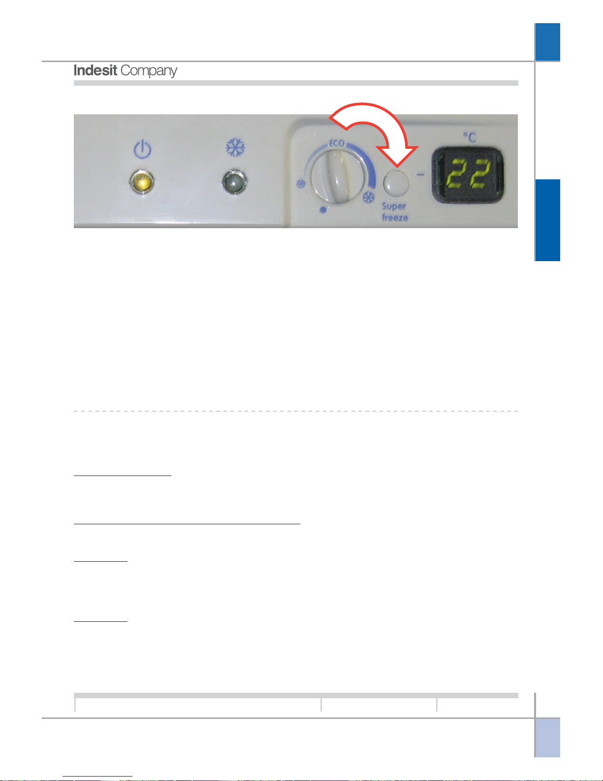
SUPER FREEZER FUNCTION:
This function provides optimal freezing of food in the
freezer compartment, conserving properties of texture and flavour.
Activating this function forces the compressor run
continuously thereby obtaining maximum freezing
power in the freezer compartment.
The fan starts after a time interval parameterised in
the EEPROM memory from the compressor ON
time, thereby displacing the cold air from the evaporator coil and allowing the freezer compartment to
be chilled.
The function cannot be activated in the presence of
alarm signals. Activation of an alarm mode or switching off the appliance automatically causes this function to be deactivated.
This function is deactivated in the following cases:
pressing the relative button again; automatically,
when the maximum activation time (24 hours) is
reached; when the freezer air temperature sensor
detects a temperature below a value parameterised
in the EEPROM for a time parameterised in the
memory.
When the function is deactivated the appliance
resumes the operating mode defined previously by
the user. The ECO or HOLIDAY functions can be
selected, although they will only become operational
when the SUPER FREEZER procedure has terminated.
In the case of a faulty freezer air sensor this function is timer controlled.
In case of electrical power failures the function will
be reactivated automatically when power is restored,
completing the remaining hours, unless a temperature alarm occurs in this interval.
SUPER COOL FUNCTION:
When the SUPER COOL function is inhibited the
appliance returns to the setting that was active before the SUPER COOL function was selected.
The user can also activate the ECO or HOLIDAY
functions, which will become operational as soon as
the SUPER COOL function has been deactivated. The
SUPER COOL function cannot be activated if the HOLI-
DAY function is active. In the case of a faulty refrigerator air sensor, this function is timer controlled.
In case of electrical power failures the function is
resumed automatically when power is restored, completing the remaining cycles, except in the presence
of a temperature alarm.
This function allows optimal chilling of large quantities of food in the refrigerator compartment by altering the refrigerator On and Off set-points in accordance with parameters stored in the EEPROM
memory and it is maintained for the number of cycles stored in the memory. The cold air transferred
by the fan via the damper serves to chill the refrigerator compartment.
The SUPER COOL function cannot be activated if
either of the two alarm modes is active.
Activation of an alarm mode or switching off the appliance or only the refrigerator compartment automatically causes this function to be deactivated.
Activation of the SUPER COOL function can be performed by the user pressing button (1) in which case
LED (3) will illuminate to confirm the function is active; the function is deactivated by the user pressing
the button again, or it will be deactivated automatically at the end of the procedure (number of cycles)
as defined in the EEPROM memory.
O
PERATION
G
B
19
Service Manual
New Electronic Cold Platform 2005
Edition
2005.03.25
Language
English
HOLIDAY FUNCTION:
alarms are present. Since the two functions are not
compatible it is not possible to select the SUPER
COOL or SUPER FREEZER functions if the knob is
set to HOLIDAY. If these two functions are already
active when the HOLIDAY function is selected, SUPER COOL and SUPER FREEZER will be terminated normally, after which the HOLIDAY function
will start. If one or more of the sensors is faulty, the
function will be controlled by the main PCB utilising
alternative parameters. In case of electrical power
failures the function will be reactivated automatically
when power is restored.
In case of minimum use of the refrigerator compartment this function makes it possible to store food
while reducing power consumption to the minimum
(E.g. during holiday periods the freezer can remain
full and the refrigerator empty).
The function is activated by turning the refrigerator knob
(2) to the HOLIDAY setting (a double beep will sound
to indicate that the function is active)., To deactivate
the function move the knob away from the HOLIDAY
position (the appliance will emit a single beep) and the
appliance will resume normal operation.
The HOLIDAY function cannot be activated when
ECO FUNCTION:
This function allows storage of food with the lowest
possible power consumption while ensuring excellent results.
The function can be activated by turning the fridge
(2) and freezer (6) knobs to the ECO setting.
To deactivate the function simply turn one of the two
knobs away from the ECO setting.
The compressor starts in the presence of a cooling
demand from either of the two compartments. To
optimise operation of the appliance there is a fixed
time setting for operation of the freezer at the end of
a refrigerator cooling demand; this interval can vary
in accordance with the temperature read by the
freezer sensor. Normally, the ECO function adjustment corresponds to the adjustment utilised to calculate power consumption in compliance with European regulations. The SUPER FREEZER and SUPER FRIDGE functions can be activated when the
ECO function is set. These functions will assume
priority over the ECO function. The appliance returns
to ECO function mode once the conditions are met
to deactivate the priority procedure. If one or more
of the sensors is faulty, the appliance will be controlled by the main PCB utilising alternative parameters.
In case of electrical power failures the function will
be reactivated automatically when power is restored.
O
PERATION
G
B
20
Service Manual
New Electronic Cold Platform 2005
Edition
2005.03.25
Language
English
ALARMS MANAGEMENT:
Alarms serve to notify the user of specific conditions such as: prolonged opening of fridge door; excessive
temperature in freezer compartment.
Door Open Alarm:
If the fridge door is kept open for a time longer than that defined by a parameter set in EEPROM memory,
an audible signal is emitted and the fridge lamp flashes at regular intervals. Close the door to reset the
alarm.
Freezer Compartment Temperature Alarm:
There are two types of alarms that can be generated if the freezer compartment temperature rises excessively:
Alarm A1:
In this case it is still possible to recover the food in the freezer by cooking it immediately and either consuming it or re-freezing it once cooked. LEDs 3 and 5 flash on the appliance control panel to indicate the
presence of the alarm, while a beeper signal is emitted at the same time.
Alarm A2:
In this case the food in the freezer compartment must be discarded. LEDs 3, 4 and 5 flash on the appliance
control panel to indicate the presence of the alarm, while a beeper signal is emitted at the same time.
In alarm status the appliance inhibits all functions or adjustments to force a specific operating mode with
specific On/ Off thresholds that set the freezer compartment temperature to given values in relation to the
type of alarm (A1 or A2); the new On / Off thresholds for the two alarm types are parameterised in the
EEPROM memory. During alarm status forced defrost cycles are executed, activated once the number of
hours parameterised in the EEPROM memory have elapsed, as in normal operation. To reset the alarm and
restore normal operation, the appliance must be set to LOGICAL OFF (freezer knob set to minimum).
The beeper can be muted by opening and closing the refrigerator door. When alarm status is reset the
timer-controlled defrost cycles are deactivated, but if the alarm reset occurs during a defrost cycle, the
alarm is reset but the current defrost cycle continues to its natural conclusion. If the appliance is set to
logical OFF with A1 or A2 active, and then switched on again after a fixed number of minutes as parameterised
in the EEPROM memory, a defrost cycle is forced after which the appliance will resume operation in accordance with the settings that were present before the alarm.
Once the appliance has entered alarm status it is not possible to quit except by means of a reset procedure
(the only possible change is the transition from alarm A1 to alarm A2). In the event of a power failure, the
state present at the time of interruption is resumed when power is restored.
Control of freezer compartment temperature, performed by means of the freezer air temperature sensor, is
executed continuously during appliance operation. In the event of a freezer air sensor fault, the alarms will
no longer be displayed.
Temperature control does not start for a time parameterised in the EEPROM memory from the first poweron of the appliance, thus avoiding the possible occurrence of alarms during the testing phases at the first
power-on at the user’s home.
When the appliance is ON, the temperature control is inhibited for a given time interval parameterised in the
EEPROM memory in order to give the compartment time to cool without generating any superfluous alarms.
After a mains power failure the freezer compartment temperature is checked immediately, since prolonged
absence of electrical power is the main cause for heating of the appliance.
O
PERATION
G
B
21
Service Manual
New Electronic Cold Platform 2005
Edition
2005.03.25
Language
English
8°C
-6°C
2°C
Temperature control and alarm signalling are managed by means of three thresholds: Check Threshold
(the control strategy becomes more intensive when this threshold is exceeded); Threshold A1: when exceeded, alarm
A1 is activated; Alarm threshold A2: when exceeded, alarm A2 is activated. The values of the three thresholds are parameterised in the EEPROM memory..
If the control temperature exceeds the Check Threshold but does not exceed the A1 Alarm threshold, a
delay time T1 is activated (parameterised in the EEPROM) before performing the next control, to prevent
the generation of alarm signals when the placement of large quantities of warm food in the freezer compartment near the freezer air sensor causes unreliable transient temperature readings. At the same time another time interval T2 is activated (parameterised on the EEPROM) after which, if the temperature is constantly maintained between the Check Threshold and the Alarm A1 Threshold, alarm A1 is forced because
the persistence of a temperature in this range for this period of time is anyway a symptom of faulty operation
and constitutes a risk for the correct preservation of the food.
At the time of activation of alarm A1 also a time interval T3 is activated (parameterised in the EEPROM)
after which, if an alarm reset has not been executed, alarm A2 is forced, since in the situation of alarm A1
the freezer compartment is set to a temperature that may not be the same as the temperature selected by
the user. This time interval is reset also when power is restored after a mains power failure.
THERMOSTAT CONTROL.
The temperature adjustments in both the compartments are independent from each other and set individually by the relative knobs.
Freezer Compartment Adjustment:
Freezer temperature is managed by the PCB utilising the value detected by the freezer air sensor to
switch the compressor on/off.
The On / Off threshold is detected by the EEPROM
and it depends on the setting
selected by the user on the interface.
If the temperature measured by the freezer air sen-
sor is above the On threshold, a cooling demand is
activated thereby starting the compressor, the fan, and opening the damper; on the contrary, if the freezer
air sensor detects a temperature lower than the Off temperature, the cooling demand is deactivated.
T1 = 2 1/2 Hours
T2 = 24 Hours
T3 = 120 Hours
N. B.: The time and temperature values shown in this graph are EEPROM parameters and as such they are subject to modification
O
PERATION
G
B
22
Service Manual
New Electronic Cold Platform 2005
Edition
2005.03.25
Language
English
Refrigerator Compartment Adjustment:
Refrigerator temperature control is managed by the
PCB according to the temperature measured by the
refrigerator air sensor in relation to the user settings
on the interface. If the temperature measured by the
refrigerator air sensor is above the On threshold, a
cooling demand is activated thereby starting the
compressor and the refrigerator fan and opening the
damper; on the contrary, if the refrigerator air sensor detects a temperature lower than the Off temperature, the cooling demand is deactivated.
Special Conditions
Optimisation of power consumption: Temperature adjustment follows different rules if the following conditions occur:
· Only ECO ON
· Temperature detected by PCB sensor (on the PCB) between two values parameterised in the EEPROM
memory.
· Time since the last time the door was opened greater than the parameters stored in the EEPROM
memory.
· Duration of last compressor On cycle less than a parameter stored in the EEPROM memory.
If these conditions are all met, with every cooling demand from the refrigerator compartment, because of
the rise in the relative temperature above the set On threshold, also the freezer compartment is forced to
transmit a cooling demand.
Cancellation of this situation can occur if at least one of the previous conditions is no longer detected, or
because the condition persists for a time greater than the relative parameter set in the EEPROM memory.
LOADS MANAGEMENT:
Compressor Operation:
The compressor serves to compress the gas in the thermodynamic circuit in order to generate the necessary cooling capacity to chill the appliance compartments.
The compressor is managed by the Main PCB with the aid of a relay and a triac that trips, in parallel with the
relay, only at the time of compressor power-on and power-off to protect the relay from electrical arcing when
the contact is opened and closed, otherwise the compressor is powered exclusively via the relay when it is
running.
The compressor is started whenever a cooling demand is received from either of the two compartments.
When both compartments no longer require cooling, the compressor will be switched off.
In certain conditions the compressor will remain stopped despite the presence cooling demands; these
situations are as follows:
Compressor protection: the compressor switches on once a minimum safety time interval (parameterised
in the EEPROM) has elapsed since the last power off, thereby allowing the pressure of gas to reach a point
of equilibrium in the refrigerant circuit. The same minimum safety time is observed in the event of a mains
power interruption (voluntary or involuntary). This compressor protection strategy is observed only after the
product has been operating continuously for a number of hours defined in the memory. This facilitates the
execution of factory tests.

O
PERATION
G
B
23
Service Manual
New Electronic Cold Platform 2005
Edition
2005.03.25
Language
English
Long periods of activity: if the compressor runs for a time greater than a value defined in the EEPROM
memory, it is switched off even in the presence of a cooling demand from either or both compartments. This
feature is designed to protect the compressor.
Pause after defrost: at the end of every defrost cycle the compressor observes a number of protection
minutes parameterised in the EEPROM memory to allow the defrost water to drain completely.
DEFROST HEATING ELEMENTS AND DRIP TRAY:
Connection of the defrost and drip tray heating elements occurs when a defrost cycle is required; this event
is controlled by the PCB by means of a procedure that considers that total compressor run time since the
last defrost cycle, the duration of the last defrost cycle, and the duration of door open times. The purpose of
the defrost heating element is to melt any ice on the evaporating coil. This ice compromises the heat
exchange between the evaporator and the air, reducing the refrigeration properties in the two compartments of the appliance. The drip tray heating element melts any ice that detaches from the evaporator and
falls into the drip tray, and also prevents blockage of the tube that transfers defrost water from the drip tray
to the drain pipe.
The defrost and drip tray heating elements are connected in parallel and controlled by the PCB. When these
heating elements are switched on, the compressor remains switched off, even in presence of cooling demands from either of the two compartments.
Deactivation of the heating elements is managed by the freezer evaporator sensor. When the temperature
detected by the evaporator sensor reaches the value parameterised in the EEPROM memory, the defrost
and drip tray heating elements are switched off. A defrost cycle cannot last more than a given time
parameterised in the EEPROM memory.
At the end of each defrost cycle the number of hours is calculated that the compressor needs to run before
starting the next defrost cycle. This calculation is performed on the basis of the duration of the defrost cycle
that has just been terminated; specifically, if said duration is greater than an ideal value stored in the
memory, for each fixed number of extra minutes parameterised in the memory one hour is deducted from
the ideal value of compressor run hours parameterised in the memory; on the contrary, if the duration is less
than the ideal value, for each fixed number of minutes below the ideal number an hour is added to the ideal
value of compressor run hours.
This control makes it possible to anticipate the next defrost cycle if the defrost cycle that has just ended
lasted too long, and vice versa. The duration of the defrost cycle can be related to the presence of ice on the
evaporator coil, because a long defrost cycle means that an excessive amount of ice has accumulated on
the coil. The duration of door open times between two defrost cycles contributes to reducing the number of
compressor run hours that must be accumulated before the next defrost cycle. Specifically, each fixed
number of minutes in which the door is open, as parameterised in the EEPROM memory, serves to reduce
by one unit the number of compressor run hours that must be accumulated before the next defrost cycle.
Finally, the time that elapses between two defrost cycle can never be greater than a value parameterised in
the EEPROM memory or lower than another value parameterised in the EEPROM; the first strategy serves
to guarantee a defrost cycle at least every number of preset hours, while the second serves to avoid
excessively frequent defrost cycles. If the last defrost cycle was interrupted according to timer control, the
minimum time between defrost cycles is equal to another value parameterised in the EEPROM memory.
Special conditions in which a defrost cycle can occur:
1. If the SUPER FREEZE function is activated, there may be an immediate defrost cycle if the accumulated
compressor run hours are more than a parameter set in the EEPROM memory, otherwise the function
proceeds as specified.
 Loading...