

Page 1

G
B
Service Manual
MBZE 45 - 2005
Edition
18.06.2005
Language
English
All the parts included in this document are the property of Indesit Company S.p.A.
All rights reserved. This document and the information it contains are supplied without liability for possible errors or omissions; no part of this document can be reproduced, used or copied without written
permission or without being authorised by the terms of a contract clause.
SERVICE MANUAL
MBZE45 FLAGSHIP / EVER FRESH
FULL NO FROST FRIDGE-FREEZER
2005
SERVICE MANUAL
MBZE45 FLAGSHIP / EVER FRESH
FULL NO FROST FRIDGE-FREEZER
2005
Page 2
G
B
2
Service Manual
MBZE 45 - 2005
Edition
2005.06.114
Language
English
CONTENTS OF THE MANUAL: NOTE FOR THE ENGINEER
This manual is a supporting document for technical personnel. It contains a description of the various
product types, the general operating principle, and indications concerning assistance.
Technical personnel should anyway consult the specific model on
(servicenet.indesitcompany.com) to access data and updates of electrical diagrams, technical bul-
letins, and spare parts.
Page 3

G
B
3
Service Manual
MBZE 45 - 2005
Edition
2005.06.114
Language
English
CONTENTS
1. OPERATING LOGIC 4-6
Product specifications 4
EVER FRESH function/Display/Alarms 5
Description of the Pneumatic Circuit 6
2. COMPONENTS 7-8
3. WIRING DIAGRAMS 9-11
4. ASSISTANCE 12-16
Disassembly 12
Removing the HOME BAR Door 12
Adjusting the HOME BAR Door 12
Removing the HOME BAR Seal 13
Removing the Fridge Door 13-16
Page 4
G
B
4
Service Manual
MBZE 45 - 2005
Edition
2005.06.114
O
PERATION
Language
English
1. OPERATING LOGIC:
1.1. PRODUCT SPECIFICATIONS:
NF EVER FRESH VFD
On FR door:
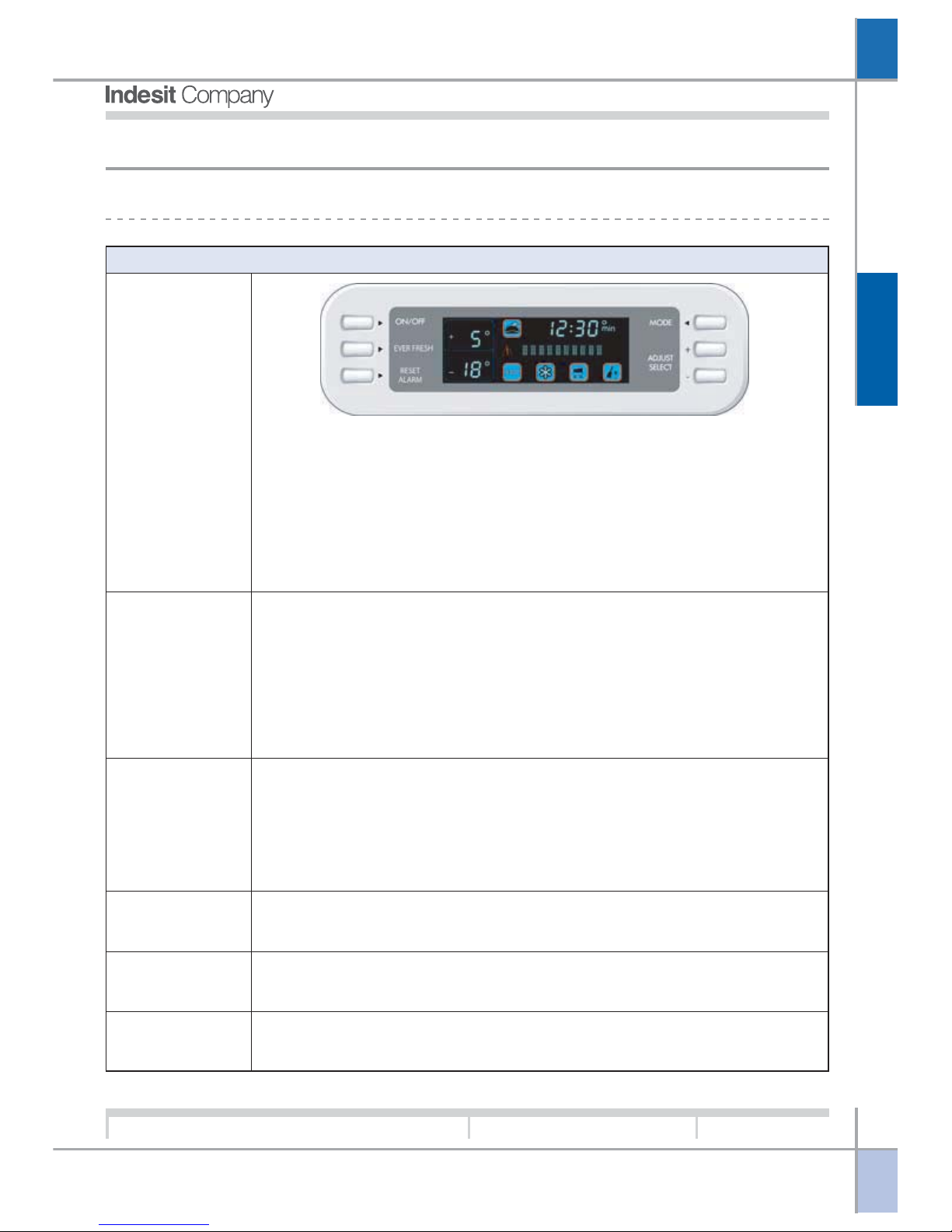
6 Buttons: (1) ON/OFF for switching appliance on and off; (2) EVER FRESH for
activation and deactivation of EVER FRESH function; (3) ALARM RESET to reset
alarms; (4) MODE, (5) ADJUST SELECT + and (6) ADJUST SELECT - to select the
required option on the display
1 VFD Display: for adjusting the freezer (FZ) and fridge (FR), setting the various
functions and user indications
1 Buzzer: on the electronic circuit board housed in the Loads control panel
User Interface
Input-Output
1 COMPRESSOR
2 FR LAMPS (in Multiflow shell)
4 DEFROST HEATING ELEMENTS in parallel (evaporator, drip tray, compartments
partition, elbow bend)
1 FZ FAN (in FZ compartment)
1 FR FAN (in FR compartment)
1 VACUUM PUMP
2 FUSES
Loads
1 FZ SOLENOID VALVE SENSOR (in contact with the FZ evaporator)
1 FZ AIR SENSOR (inside the FZ compartment)
1 FR AIR SENSOR (inside the FR compartment)
1 PCB SENSOR (on the electronic circuit board)
1 FR DOOR SWITCH (magnetic reed switch on circuit board behind control panel)
1 VACUUM SWITCH
Sensors
Between the two boards; passage on FR door hinge
Internal serial line
Outlet in the compressor compartment
External serial line
On the electronic circuit board
EEPROM memory
Page 5

G
B
5
Service Manual
MBZE 45 - 2005
Edition
2005.06.114
O
PERATION
Language
English
1.2 EVER FRESH FUNCTION / DISPLAY / ALARMS:
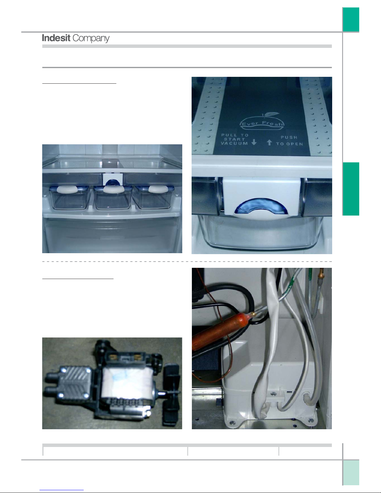
Select the vacuum position on the container cover
and position the container in the central part of the
shelf inside the fridge compartment (vacuum station) in correspondence with the mobile containervacuum pump connection; pull the lever under the
shelf to its forward position
To activate the Ever Fresh function press the relevant button once, this will cause the icon to illuminate in
blue and the message EVER FRESH ON will scroll across the display; at this point the vacuum will be
applied automatically thanks to the intervention of a vacuum switch that detects vacuum conditions in the
container. To deactivate the vacuum function manually, press the button once (the blue icon will extinguish
and the display will scroll the message EVER FRESH OFF).
After approximately 80 seconds if vacuum conditions are not detected in the containers, the appliance will emit two initial beeps, the alarm icon will
illuminate steadily, and the message “VACUUM NOT
POSSIBLE, CHECK CONTAINER” will scroll across
the display. To reset this alarm and restore normal
operation, press the ALARM RESET button twice
Page 6
G
B
6
Service Manual
MBZE 45 - 2005
Edition
2005.06.114
O
PERATION
Language
English
1.3 DESCRIPTION OF THE PNEUMATIC CIRCUIT:
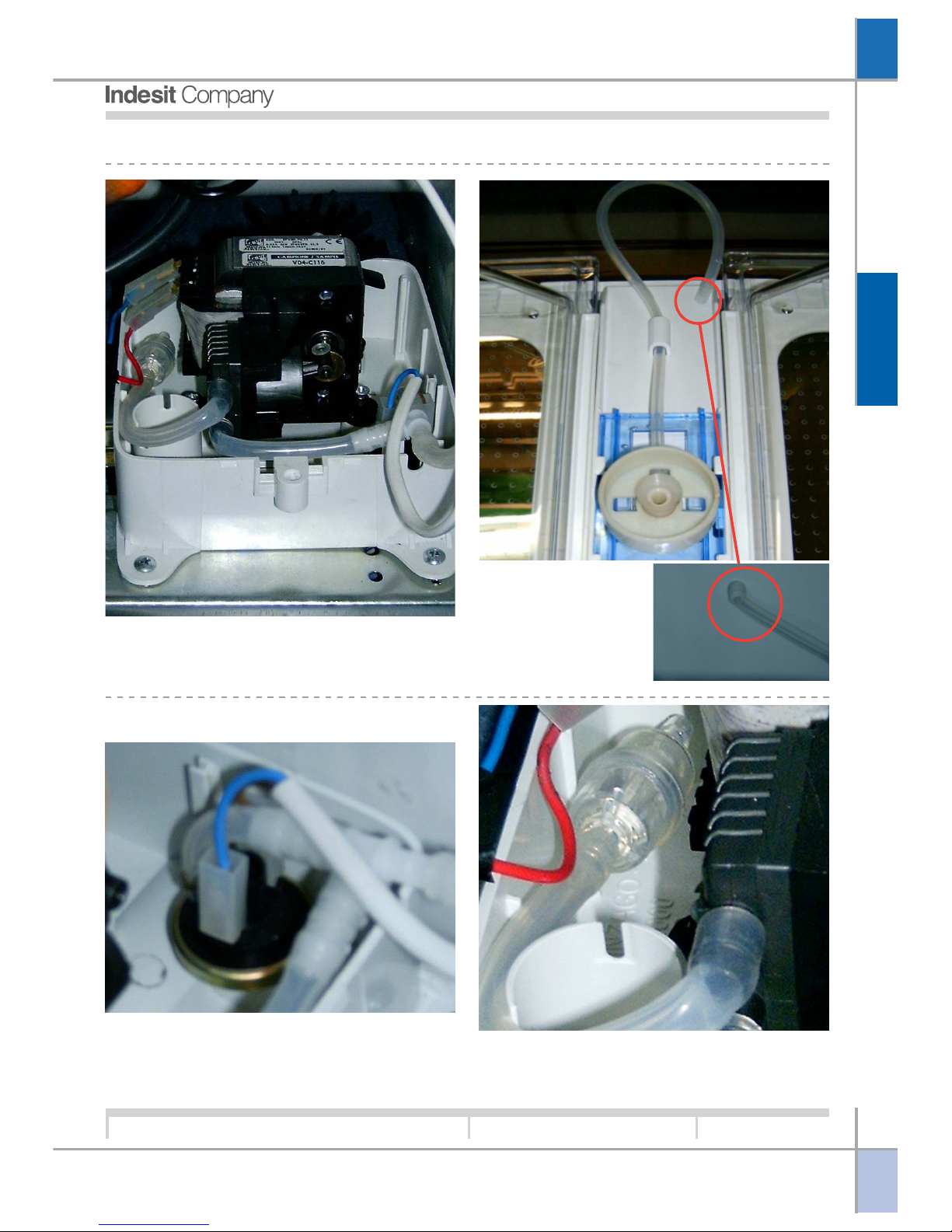
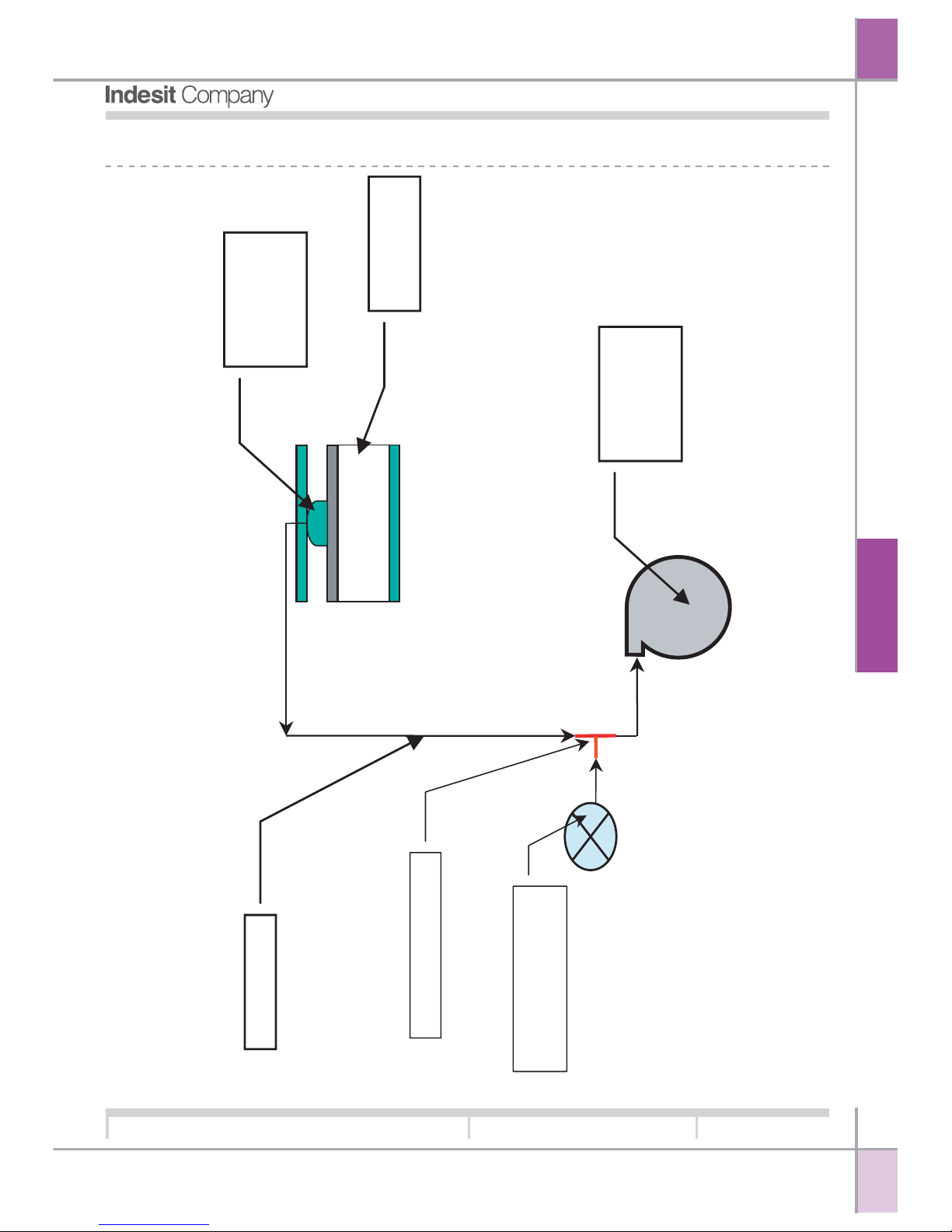
The pump is connected to the vacuum station (under the glass shelf) by a 7 mm
diameter silicone rubber hose lodged in the cabinet by embedding in foam and
coupled to the shelf at the rear of the fridge wall
The vacuum pump compartment also contains:
1 The vacuum switch responsible for detecting
vacuum conditions inside the container and consequently disconnecting the vacuum pump.
2 A filter coupled to the aspirated air extraction
hose.
Page 7
G
B
7
Service Manual
MBZE 45 - 2005
Edition
2005.06.114
C
OMPONENTS
Language
English
2. COMPONENTS:
IThe EVER FRESH device fitted to Full No Frost
fridge-freezer allows the user to store food for longer
periods by pressing the relevant button on the display and positioning the vacuum container in the
specific area of the fridge compartment.
A vacuum is created inside the containers by means
of a vacuum pump located in the area of the compressor compartment.
EVER FRESH device.
EVER FRESH pump.
Page 8
G
B
8
Service Manual
MBZE 45 - 2005
Edition
2005.06.114
C
OMPONENTS
Language
English
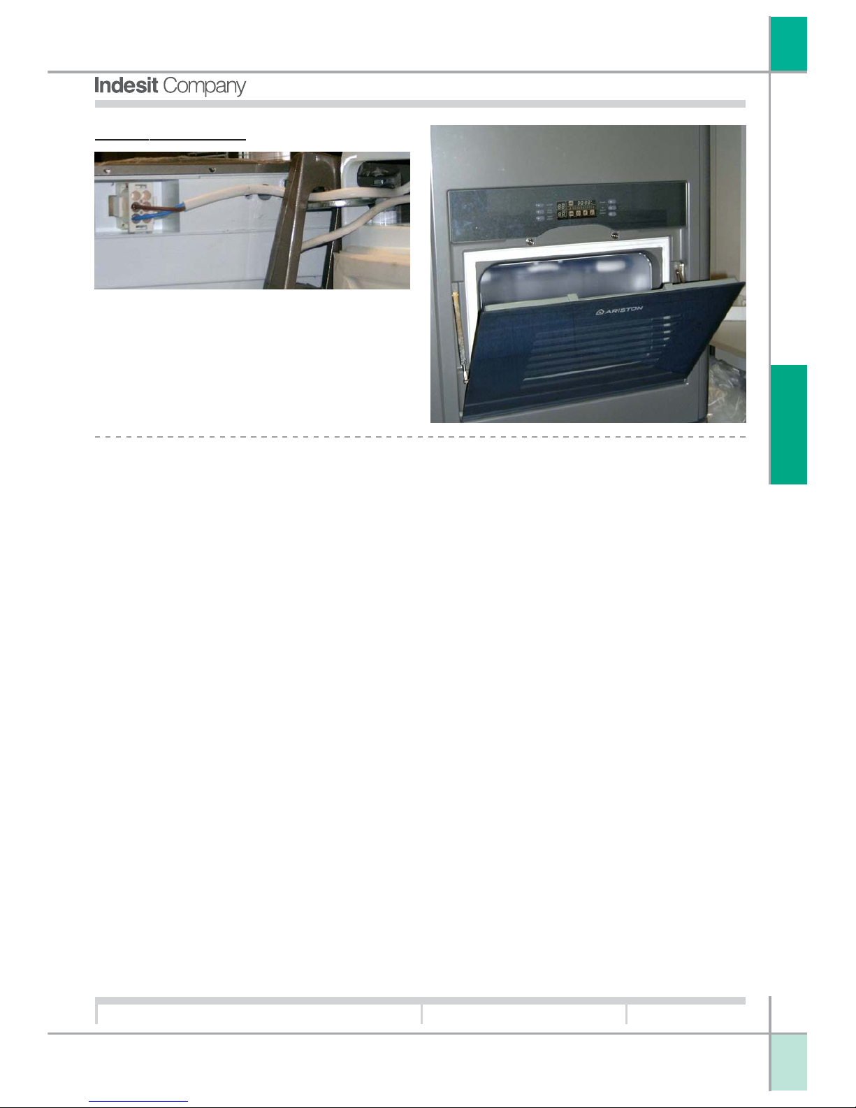
There is a flap on the fridge door allowing the user
to extract bottles from the door shelf inside the compartment without opening the fridge door.
The electrical wiring of the Home Bar door perimeter heating element transits behind the control panel
and inside the fridge door.
HOME BAR device.
Page 9
G
B
9
Service Manual
MBZE 45 - 2005
Edition
2005.06.114
W
IRING
D
IAGRAMS
Language
English
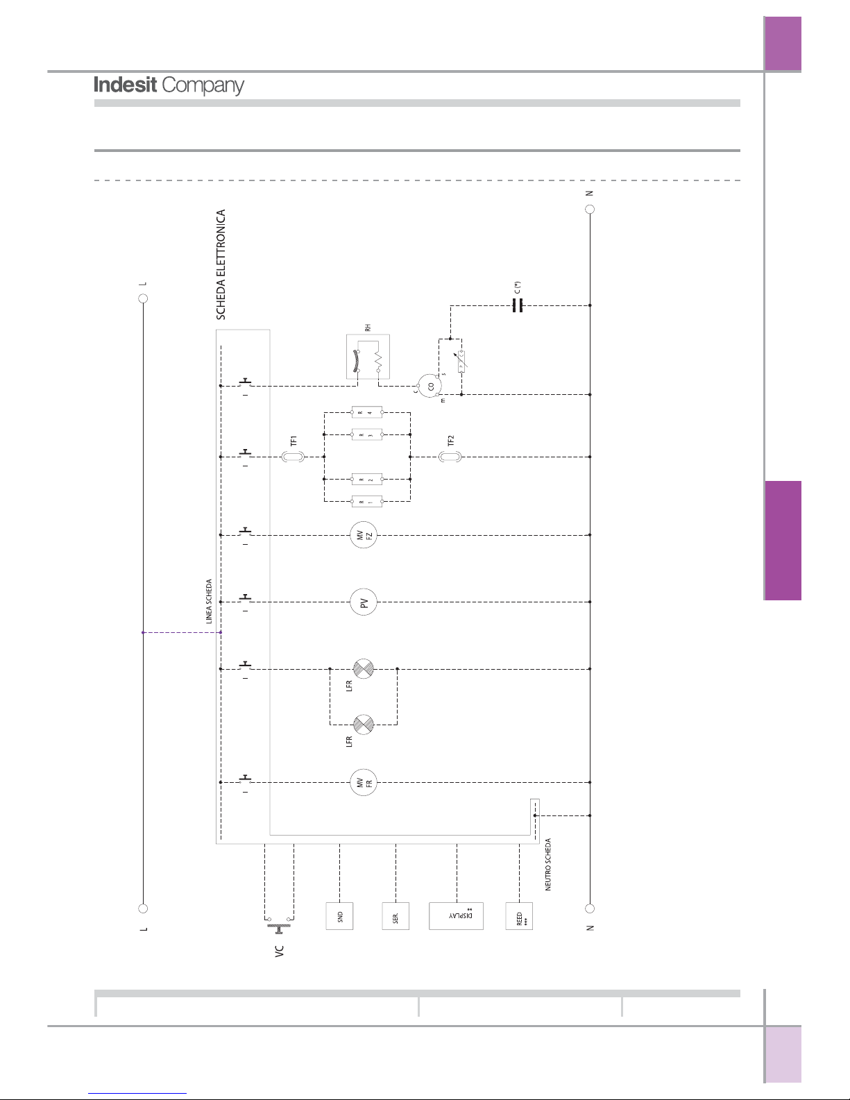
3. WIRING DIAGRAMS:
3.1 MAIN WIRING DIAGRAM:
KEY L = LINE CO: COMPRESSOR
N = NEUTRAL PTC: PTC RELAY
LFR: FRIDGE LAMP RH: THERMAL CUT-OUT
PV: VACUUM PUMP SND: SENSORS
VC: VACUUM SWITCH SER.: EXTERNAL SERIAL LINE (IF PRESENT)
MVFR: FRIDGE COMPARTMENT NF FAN C (*): START CONDENSER (IF PRESENT)
MVFZ: FREEZER COMPARTMENT NF FAN DISPLAY (**): SHOWS TEMPERATURES AND SPECIAL FUNCTIONS (IF PRESENT)
R1-R2-R3-R4: DEFROST HEATING ELEMENTS REED (***): FR DOOR SWITCH (ON PCB)
TF1 - TF2: FUSES I: CONTROL SWITCH, MANAGED BY THE CIRCUIT BOARD
Page 10
G
B
10
Service Manual
MBZE 45 - 2005
Edition
2005.06.114
W
IRING
D
IAGRAMS
Language
English
3.2 PNEUMATIC CIRCUIT:
Vacuum
Pump
ìTî Conn ection
Pressure Switch
Vacuum box
Tube
Vacuum
Station
Page 11
G
B
11
Service Manual
MBZE 45 - 2005
Edition
2005.06.114
W
IRING
D
IAGRAMS
Language
English
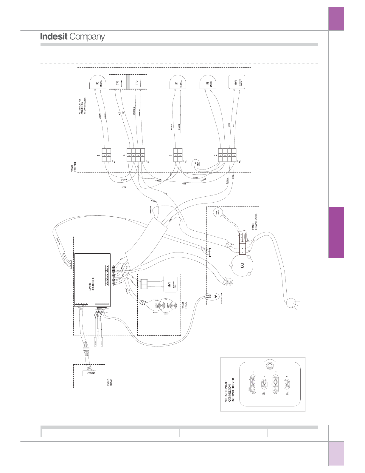
3.3 CONNECTION DIAGRAM:
Page 12
G
B
12
Service Manual
MBZE 45 - 2005
Edition
2005.06.114
A
SSISTANCE
Language
English
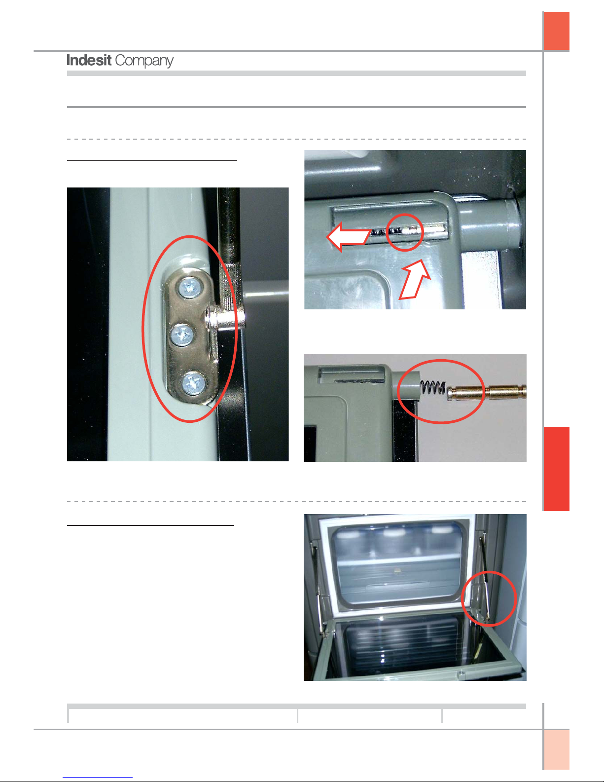
Removing the Home Bar Door:
To remove the Home Bar door:
2. Insert a screwdriver into the channel in the fixing
pins and force them inwards.
N.B. When removing the door use caution because the
spring could cause the pin to be ejected from its seat
4. ASSISTANCE:
4.1. DISASSEMBLY:
1. Remove the 6 screws securing the 2 arms
Adjusting the Home Bar Door:
To adjust the opening force of the home bar door,
rotate the arms:
1 rotate clockwise to increase opening force.
2 rotate counter-clockwise to decrease opening
force.
Page 13
G
B
13
Service Manual
MBZE 45 - 2005
Edition
2005.06.114
A
SSISTANCE
Language
English
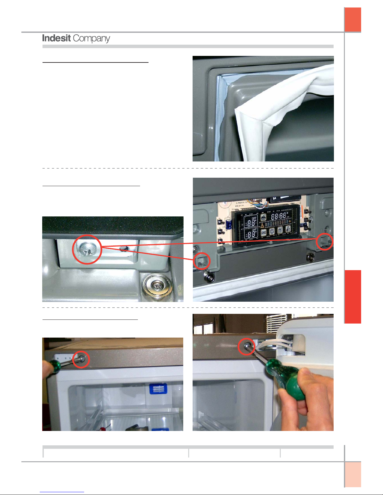
Removing the Home Bar Seal:
The seal is glued to the door; if it needs replacing
use single-component neutral cure silicone adhesive/sealant (e.g.: Dow Corning 7091)
Removing the Display PCB:
To gain access to the display PCB under the control
panel window open the home bar door and undo the
2 screws at the bottom of the control panel window.
Removing the Fridge Door:
1. Remove the control panel covers and undo the 2
screws
Page 14
G
B
14
Service Manual
MBZE 45 - 2005
Edition
2005.06.114
A
SSISTANCE
Language
English
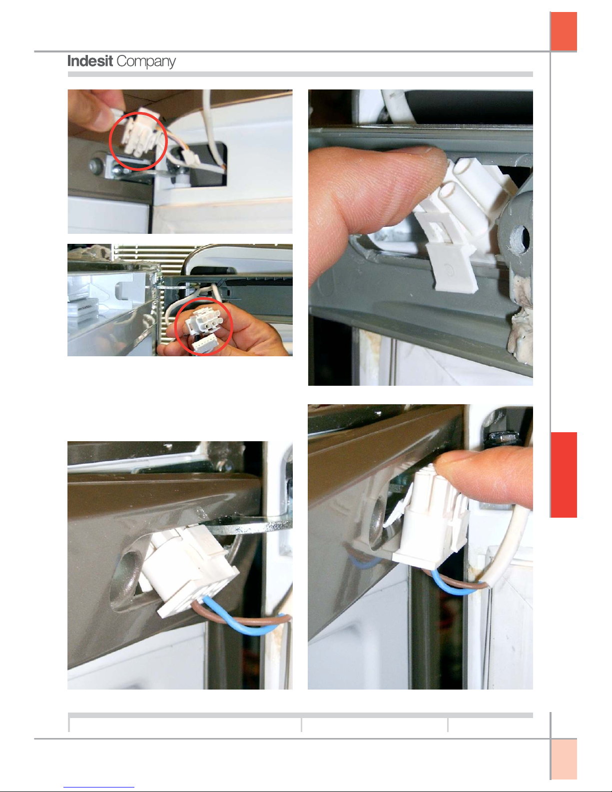
2. Disconnect the wiring from the PCB and control
panel connector.
N.B.: When routing the connector through the
hole in the instrument panel cover (and when
re-inserting it) perform the operation as shown
in the photos (1- 2-3)
1 3
2
Page 15
G
B
15
Service Manual
MBZE 45 - 2005
Edition
2005.06.114
A
SSISTANCE
Language
English
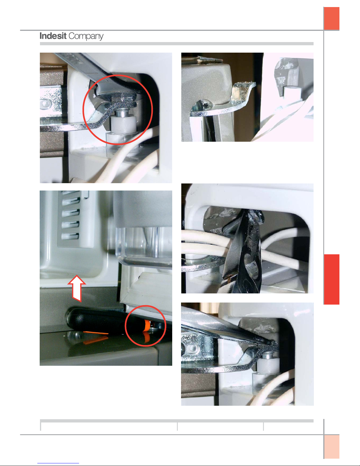
3. Unscrew the pin with a 10 mm wrench, keeping
the door slightly raised to facilitate the operation
(e.g. insert a rubber screwdriver handle in the area
of the central hinge between the fridge and freezer
doors)
4. Disengage the door from the hinge and lift
N.B. Important: when refitting the pin in its seat,
keep the door slightly raised and use a pair of
long-nosed pliers.
Page 16
G
B
16
Service Manual
MBZE 45 - 2005
Edition
2005.06.114
A
SSISTANCE
Language
English
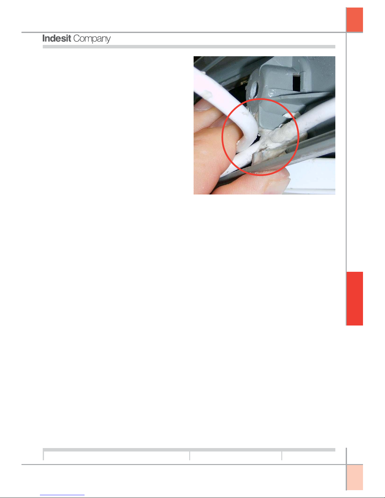
N.B. When refitting the wiring behind the control panel ensure the cables are fitted correctly
into their original locations
Page 17
G
B
Indesit Company
viale Aristide Merloni, 47
60044 Fabriano - Italy
tel. +39 0732 66 11 - telex 560196 - fax +39 0732 66 2954 - www.indesitcompany.com
Service Manual
MBZE 45 - 2005
Edition
2005.06.114
Language
English
 Loading...