

Indesit KN3N65SA/BG Operating Instructions Manual
English
GB
Operating Instructions
COOKER AND OVEN
Contents
Operating Instructions,1
Description of the appliance-Control Panel,1
Description of the appliance-Overall view,2
Installation,3
Start-up and use,7
Cooking modes,8,
Precautions and tips,12
Care and maintenance,13
Assistance,13
KN3N65SA/BG
Polski
PL
Instrukcja obsługi
KUCHENKA I PIEKARNIK
Spis treści
Instrukcja obsługi,1
Opis urządzenia-Panel sterowania,1
Opis urządzenia-Widok ogólny,2
Instalacja,14
Uruchomienie i użytkowanie,18
Użytkowanie piekarnika,19
Zalecenia i środki ostrożności,24
Konserwacja i utrzymanie,25
Serwis Techniczny,25
P L
BG
4
5
2
1
3
6
7
8
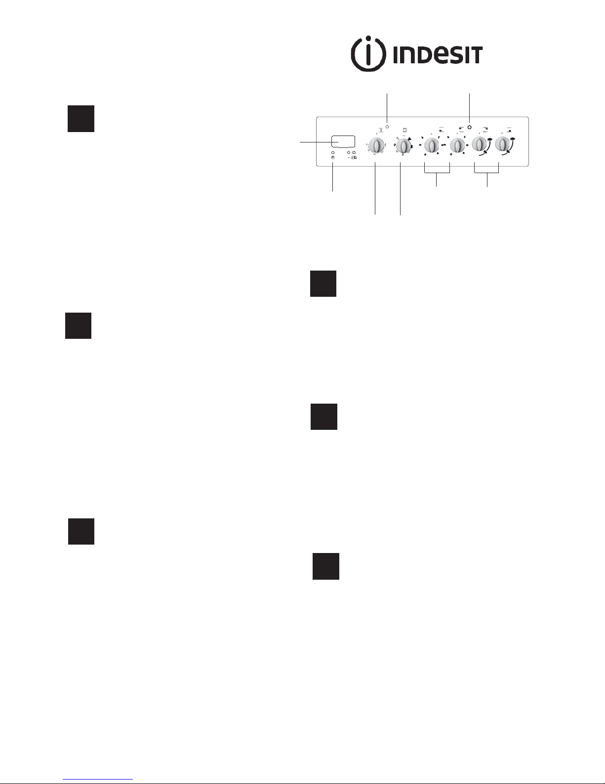
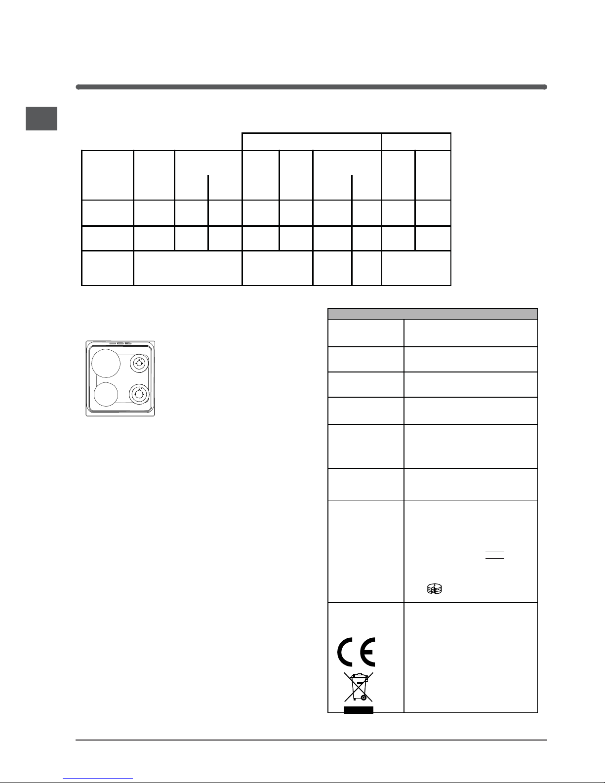
Description of the appliance
Control panel
GB
1.Electronic cooking programmer
2.TIMER button
3.THERMOSTAT knob
4.SELECTOR knob
5.THERMOSTAT indicator light
6.Electric HOTPLATE control knob
7.Hob BURNER control knob
8.ELECTRIC HOTPLATE indicator light
PL
Opis urządzenia
Panel kontrolny
1.Programator elektroniczny
2.Przycisk MINUTNIKA
3.Pokrętło TERMOSTATU
4.Pokrętło PROGRAMÓW PIEKARNIKA
5.Lampka kontrolna TERMOSTATU
6.Pokrętła ELEKTRYCZNYCH PÓL GRZEJNYCH
7.Pokrętło PALNIKÓW PŁYTY GRZEJNEJ
8.Lapmka kontrolna ELEKTRYCZNYCH PÓL GRZEJNYCH
RS
Инструкции за употреба
ЕЛЕКТРИЧЕСКА ПЕЧКА И ФУРНА
Резюме
Инструкции за употреба,1
Описание на уреда- Управляващ панел,1
Описание на уреда-Общ преглед,2
Инсталиране,26
Пуск и експлоатация, 30
Използване на фурната,33
Предпазни мерки и препоръки,35
Поддръжка и почистване,36
Техническо обслужване,36
Описание на уреда
Управляващ панел
BG
1. Електронна готвене програмист
2. TIMER
3. Бучка термостат
4. ключа за избор
5. Светлинен индикатор на термостата
6. Копчето за управление на електрически котлон
7. Копчето за управление на Котлон горелката
8. Светлинен индикатор на електрически котлон
Български
2
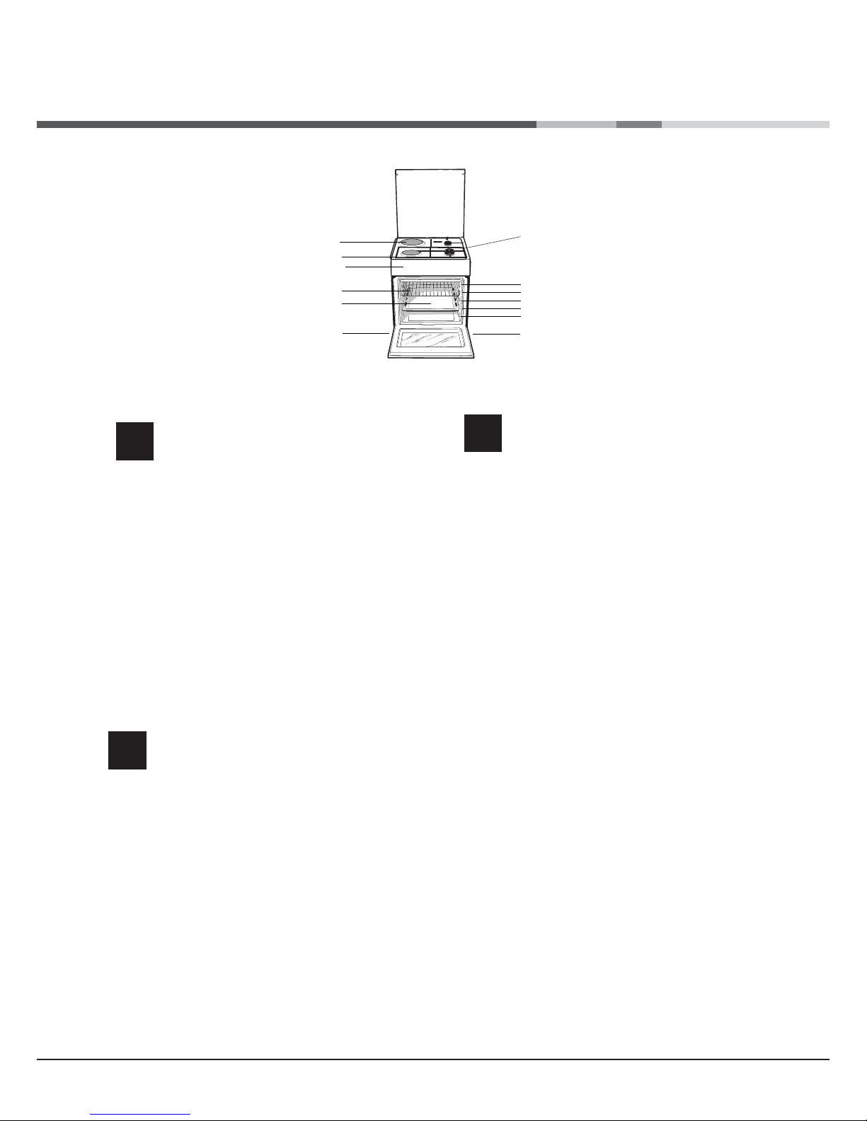
1.ELECTRIC HOTPLATE
2. Hob Grid
3.Control panel
4.Sliding grill rack
5.DRIPPING pan
6.Adjustable foot
7. Hob burner
8.Containment surface for spills
9.GUIDE RAILS for the sliding racks
10.position 5
11.position 4
12.position 3
13.position 2
14.position 1
Description of the appliance
Overall view
GB
PL
1.Elektryczna płyta grzejna
2 Ruszta płyty podpalnikowej
3.Panel kontrolny
4.Półka ruszt
5.Półka brytfanna
6.Nóżki regulowane
7.Palnik gazowy
8. Płyta podpalnikowa
9. Prowadnice półek
10. pozycja 5
11.pozycja 4
12.pozycja 3
13.pozycja 2
14.pozycja 1
Opis urządzenia
Widok ogólny
1 .Електрически котлони
2 .Горна решетка
3 .Командно табло
4 .Решетка
5 .Тава
6 .Регулируеми крачета
7. Газови горелки
8 .Плот
9. BOДAЧИ за двата
10.Положение 5
11 Положение 4
12 Положение 3
13 Положение 2
14 Положение 1
Описание на уреда
Общ преглед
BG
2
1
3
4
5
6
6
10
11
12
13
14
9
8
7
GB
3
! Before operating your new appliance please read
this instruction booklet carefully. It contains important
information concerning the safe installation and
operation of the appliance.
! Please keep these operating instructions for future
reference. Make sure that the instructions are kept with
the appliance if it is sold, given away or moved.
! The appliance must be installed by a qualified
professional according to the instructions provided.
! Any necessary adjustment or maintenance must be
performed after the cooker has been disconnected
from the electricity supply.
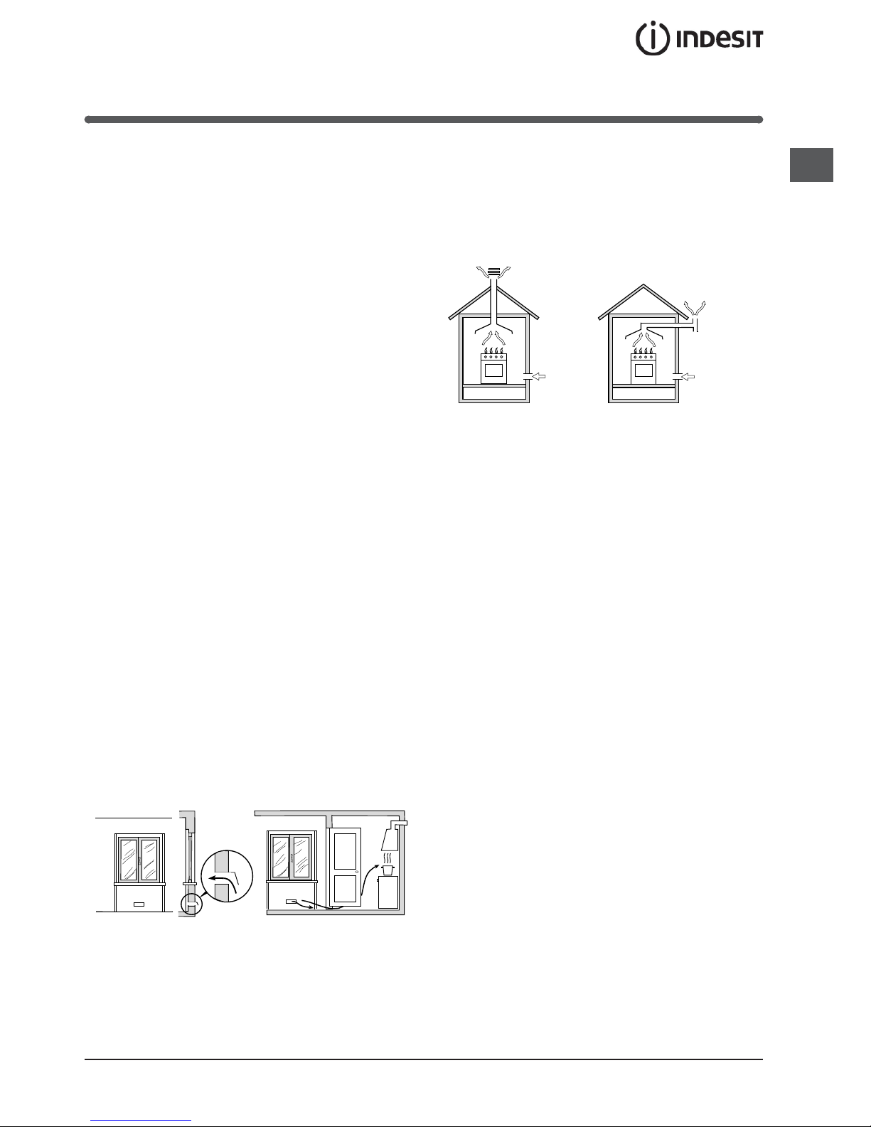
Room ventilation
The appliance may only be installed in permanentlyventilated rooms, according to current national
legislation. The room in which the appliance is installed
must be ventilated adequately so as to provide as
much air as is needed by the normal gas combustion
process (the flow of air must not be lower than 2 m
3
/h
per kW of installed power).
The air inlets, protected by grilles, should have a duct
with an inner cross section of at least 100 cm
2
and
should be positioned so that they are not liable to even
partial obstruction (see gure A).
These inlets should be enlarged by 100% - with a
minimum of 200 cm
2
- whenever the surface of the
hob is not equipped with a flame failure safety device.
When the flow of air is provided in an indirect manner
from adjacent rooms (see gure B), provided that these
are not communal parts of a building, areas with
increased fire hazards or bedrooms, the inlets should
be fitted with a ventilation duct leading outside as
described above.
! After prolonged use of the appliance, it is advisable to
open a window or increase the speed of any fans used.
Disposing of combustion fumes
The disposal of combustion fumes should be
guaranteed using a hood connected to a safe and
efficient natural suction chimney, or using an electric
fan that begins to operate automatically every time the
appliance is switched on (see gure).
! The liquefied petroleum gases are heavier than air
and collect by the floor, therefore all rooms containing
LPG cylinders must have openings leading outside so
that any leaked gas can escape easily.
LPG cylinders, therefore, whether partially or
completely full, must not be installed or stored in rooms
or storage areas that are below ground level (cellars,
etc.). Only the cylinder being used should be stored
in the room; this should also be kept well away from
sources of heat (ovens, chimneys, stoves) that may
cause the temperature of the cylinder to rise above
50°C.
Positioning and levelling
! It is possible to install the appliance alongside
cupboards whose height does not exceed that of the
hob surface.
! Make sure that the wall in contact with the back of
the appliance is made from a non-flammable, heatresistant material (T 90°C).
To install the appliance correctly:
• Place it in the kitchen, dining room or the bed-sit (not
in the bathroom).
• If the top of the hob is higher than the cupboards,
the appliance must be installed at least 200 mm away
from them.
• If the cooker is installed underneath a wall cabinet,
there must be a minimum distance of 420 mm
between this cabinet and the top of the hob.
Installation
Adjacent room Room requiring
ventilation
A
B
Ventilation opening for
comburent air
Increase in the gap
between the door and
the flooring
A
Fumes channelled
straight outside
Fumes channelled through a
chimney or a branched flue
system (reserved for cooking
appliances)

4
GB
• If the cooker is
installed underneath a
wall cabinet, there must
be a minimum distance
of 420 mm between this
cabinet and the top of
the hob.
This distance should be
increased to 700 mm
if the wall cabinets are
flammable (see gure).
• Do not position blinds behind the cooker or less than
200 mm away from its sides.
• Any hoods must be installed according to the
instructions listed in the relevant operating manual.
Levelling
If it is necessary to level the
appliance, screw the adjustable
feet into the places provided on
each corner of the base of the
cooker (see gure).
The legs* fit into the slots on the
underside of the base of the
cooker.
Electrical connection
Install a standardised plug corresponding to the load
indicated on the appliance data plate (see Technical
data table).
The appliance must be directly connected to the
mains using an omnipolar circuit-breaker with a
minimum contact opening of 3 mm installed between
the appliance and the mains. The circuit-breaker must
be suitable for the charge indicated and must comply
with NFC 15-100 regulations (the earthing wire must
not be interrupted by the circuit-breaker). The supply
cable must be positioned so that it does not come into
contact with temperatures higher than 50°C at any
point.
Before connecting the appliance to the power supply,
make sure that:
• The appliance is earthed and the plug is compliant with
the law.
• The socket can withstand the maximum power of the
appliance, which is indicated by the data plate.
HOOD
420
Min.
min.
650
mm. with hood
min.
700
mm. without hood
mm.
600
Min. mm.
420
Min. mm.
• The voltage is in the range between the values
indicated on the data plate.
• The socket is compatible with the plug of the
appliance. If the socket is incompatible with the
plug, ask an authorised technician to replace it. Do
not use extension cords or multiple sockets.
! Once the appliance has been installed, the power
supply cable and the electrical socket must be easily
accessible.
! The cable must not be bent or compressed.
! The cable must be checked regularly and replaced
by authorised technicians only.
! The manufacturer declines any liability should
these safety measures not be observed.
Gas connection
Connection to the gas network or to the gas cylinder
may be carried out using a flexible rubber or steel hose,
in accordance with current national legislation and after
making sure that the appliance is suited to the type of
gas with which it will be supplied (see the rating sticker
on the cover: if this is not the case see below). When
using liquid gas from a cylinder, install a pressure
regulator which complies with current national
regulations. To make connection easier, the gas
supply may be turned sideways*: reverse the position
of the hose holder with that of the cap and replace the
gasket that is supplied with the appliance.
! Check that the pressure of the gas supply is
consistent with the values indicated in the Table
of burner and nozzle specifications (see below).
This will ensure the safe operation and durability of
your appliance while maintaining efficient energy
consumption.
Gas connection using a flexible rubber hose
Make sure that the hose complies with current national
legislation. The internal diameter of the hose must
measure: 8 mm for liquid gas supply; 13 mm for
methane gas supply.
Once the connection has been performed, make sure
that the hose:
• Does not come into contact with any parts that
reach temperatures of over 50°C.
• Is not subject to any pulling or twisting forces and
that it is not kinked or bent.
• Does not come into contact with blades, sharp
corners or moving parts and that it is not
compressed.
GB
5
• Is easy to inspect along its whole length so that its
condition may be checked.
• Is shorter than 1500 mm.
• Fits firmly into place at both ends, where it will
be fixed using clamps that comply with current
regulations.
! If one or more of these conditions is not fulfilled
or if the cooker must be installed according to the
conditions listed for class 2 - subclass 1 appliances
(installed between two cupboards), the flexible steel
hose must be used instead (see below).
Connecting a flexible jointless stainless steel pipe
to a threaded attachment
Make sure that the hose and gaskets comply with
current national legislation.
To begin using the hose, remove the hose holder on
the appliance (the gas supply inlet on the appliance is
a cylindrical threaded 1/2 gas male attachment).
! Perform the connection in such a way that the hose
length does not exceed a maximum of 2 metres,
making sure that the hose is not compressed and does
not come into contact with moving parts.
Checking the tightness of the connection
When the installation process is complete, check the
hose fittings for leaks using a soapy solution. Never
use a flame.
Adapting to different types of gas
It is possible to adapt the appliance to a type of gas
other than the default type (this is indicated on the
rating label on the cover).
Adapting the hob
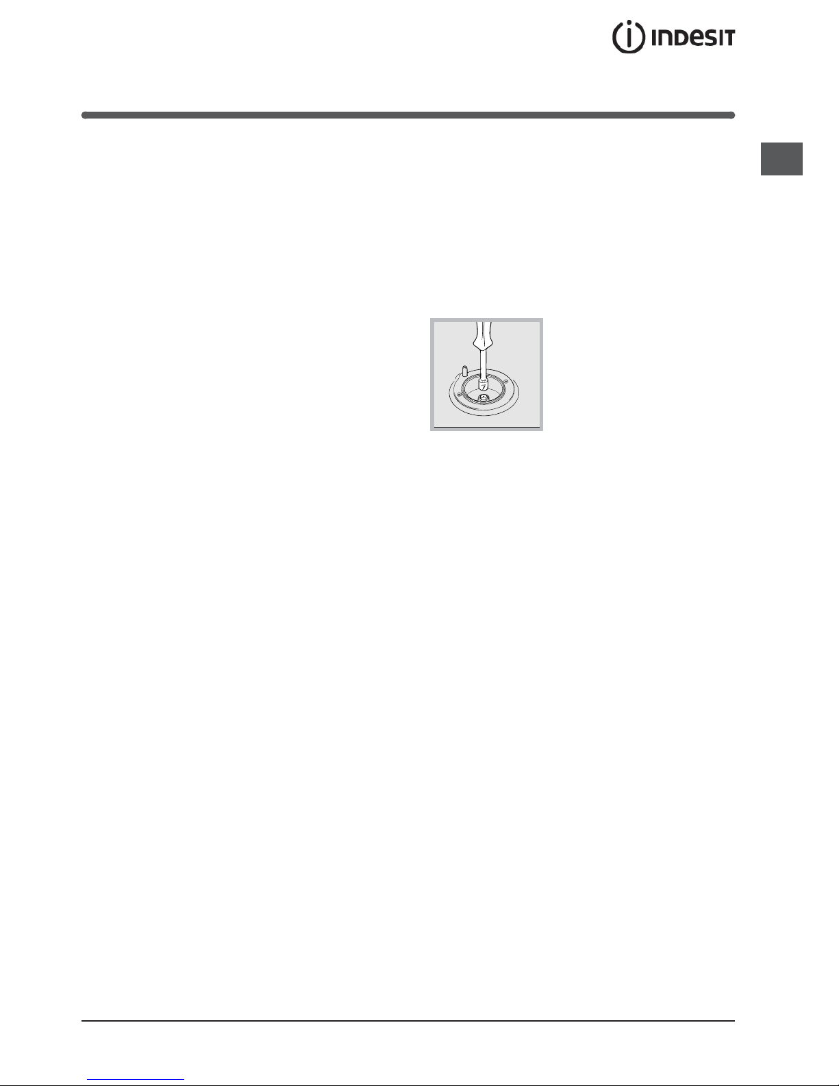
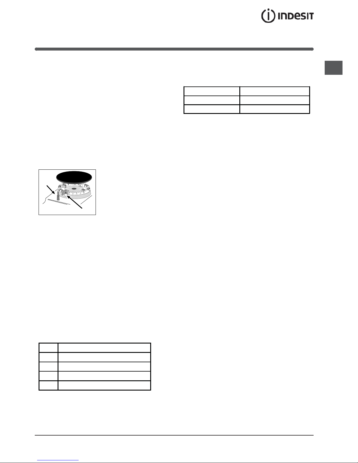
Replacing the nozzles for the hob burners:
1. Remove the hob grids and slide the burners off their
seats.
2. Unscrew the nozzles using
a 7 mm socket spanner (see
gure), and replace them with
nozzles suited to the new type
of gas (see Burner and nozzle
speci cations table).
3. Replace all the components
by following the above
instructions in reverse.
Adjusting the hob burners’ minimum setting:
1. Turn the tap to the minimum position.
2. Remove the knob and adjust the regulatory screw,
which is positioned inside or next to the tap pin, until
the flame is small but steady.
! If the appliance is connected to a liquid gas supply,
the regulatory screw must be fastened as tightly as
possible.
3. While the burner is alight, quickly change the
position of the knob from minimum to maximum and
vice versa several times, checking that the flame is not
extinguished.
! The hob burners do not require primary air
adjustment.
! After adjusting the appliance so it may be used with
a different type of gas, replace the old rating label with
a new one that corresponds to the new type of gas
(these labels are available from Authorised Technical
Assistance Centres).
! Should the gas pressure used be different (or vary
slightly) from the recommended pressure, a suitable
pressure regulator must be fitted to the inlet hose in
accordance with current national regulations relating to
“regulators for channelled gas”.
6
GB
Table of burner and nozzle specifications
S
R
ø 145
ø 180
KN3N65SA/BG
At 15°C and 1013 mbar- dry gas
** Propane P.C.S. = 50,37 MJ/Kg
*** Butane P.C.S. = 49,47 MJ/Kg
Natural P.C.S. = 37,78 MJ/m
3
Table 1 Liquid Gas Natural Gas
Burner Diameter
(mm)
Thermal Power
kW (p .c.s.*)
By-Pass
1/100
Nozzle
1/100
Flow*
g/h
Nozzle
1/100
Flow*
l/h
Nominal Reduce-d(mm) (mm) *** ** (mm)
Fast
(Large)(R)
100 3.00 0.7 41 87 218 214 128 286
Semi Fast
(Medium)(S)
75 1.90 0.4 30 70 138 136 104 181
Supply
Pressures
Nominal (mbar)
Minimum (mbar)
Maxi mu m (mb ar)
28-30
20
35
37
25
45
20
17
25
TABLE OF CHARACTERISTSICS
Dimensions (with
drawn guide rails)
width 39 cm
height 34 cm
depth 41 cm
Volume (with
drawn guide rails)
54 l
Maximum absorber
power:
5600 W
Dimensions of the
lower compartment
width 42 cm
height 23 cm
depth 44 cm
Burners
may be adapted for use with any type
of gas shown on the data plate, which
is located inside the flap or, after the
oven compartment has been opened,
on the left-hand wall inside the oven.
Electric Plate
Rapid Ø 145 mm: 1500 W
Rapid Ø 180 mm: 2000 W
ENERGY LABEL
Directive 2002/40/EC on the label of
electric ovens.
Standard EN 50304
Energy consumption for Natural
convection – heating mode:
Convection;
Declared energy consumption for
Forced convection Class – heating
mode: Baking
This appliance conforms to the
following European Economic
Community directives: 2006/95/EC
dated 12/12/06 (Low Voltage) and
subsequent amendments 2004/108/EC dated 15/12/04
(Electromagnetic Compatibility) and
subsequent amendments - 93/68/EEC
dated 22/07/93 and subsequent
amendments.
2002/96/EC
2009/142 of 30/11/09 (Gas)
1275/2008 (Stand-by/ Off mode)
GB
7
Start-up and use
Using the hob
Lighting the burners
For each BURNER knob there is a full ring showing the
strength of the flame for the relevant burner.
To light one of the burners on the hob:
1. Bring a flame or gas lighter close to the burner.
2. Press the BURNER knob and turn it in an
anticlockwise direction so that it is pointing to the
maximum flame setting .
3. Adjust the intensity of the flame to the desired level
by turning the BURNER knob in an anticlockwise
direction. This may be the minimum setting , the
maximum setting or any position in between the two.
If the appliance is fitted with an electronic lighting
device* (C), press the
BURNER knob and turn it in
an anticlockwise direction,
towards the minimum flame
setting, until the burner
is lit. The burner may be
extinguished when the knob
is released. If this occurs,
repeat the operation, holding the knob down for a longer
period of time.
f the appliance is equipped with a flame failure safety
device (X), press and hold the BURNER knob for
approximately 3-7 seconds to keep the flame alight
and to activate the device.
! If the flame is accidentally extinguished, switch off the
burner and wait for at least 1 minute before attempting
to relight it.
To switch the burner off, turn the knob until it reaches
the stop position •.
Electric hotplates
The corresponding knob may be turned clockwise
or anti-clockwise and set to any of the six different
positions:
When the selector knob is in any position other than the
off position, the ‘on’ light is illuminated.
Practical advice on using the burners
For the burners to work in the most efficient way
possible and to save on the amount of gas consumed,
it is recommended that only pans that have a lid and
a flat base are used. They should also be suited to the
size of the burner:
To identify the type of burner, please refer to the
diagrams contained in the “Burner and nozzle
specifications”.
Using the oven
! The first time you use your appliance, heat the empty
oven with its door closed at its maximum temperature
for at least half an hour. Ensure that the room is well
ventilated before switching the oven off and opening
the oven door. The appliance may emit a slightly
unpleasant odour caused by protective substances
used during the manufacturing process burning away.
! Before operating the product, remove all plastic film
from the sides of the appliance.
! Never put objects directly on the bottom of the oven;
this will avoid the enamel coating being damaged.
1. Select the desired cooking mode by turning the
SELECTOR knob.
2. Select the recommended temperature for the
cooking mode or the desired temperature by turning
the THERMOSTAT knob.
A list detailing cooking modes and suggested cooking
temperatures can be found in the relevant table (see
Oven cooking advice table).
During cooking it is always possible to:
• Change the cooking mode by turning the
SELECTOR knob.
• Change the temperature by turning the
THERMOSTAT knob.
• Stop cooking by turning the SELECTOR knob to the
“0” position.
! Always place cookware on the rack(s) provided.
THERMOSTAT indicator light
When this is illuminated, the oven is generating heat.
It switches off when the inside of the oven reaches
the selected temperature. At this point the light
illuminates and switches off alternately, indicating
that the thermostat is working and is maintaining the
temperature at a constant level.
X
C
Setting Normal or Fast Plate
0
Off
1
Low
2 - 5
Medium
6
High
Burner ř Cookware diameter (cm)
Fast (R) 24 - 2 6
Semi Fa st (S) 16 - 2 0
8
GB
same. A maximum of 2 racks can be used at the same
time, following the instructions in the section entitled:
“Cooking On More Than One Rack”.
This fan assisted mode is particularly recommended
for dishes requiring a gratin finish or for those
requiring considerably prolonged cooking times,
such as for example: lasagne, pasta bakes, roast
chicken and potatoes, etc… Moreover, the excellent
heat distribution makes it possible to use lower
temperatures when cooking roasts. This results in
less loss of juices, meat which is more tender and a
decrease in the loss of weight for the roast. The fan
assisted mode is especially suited for cooking fish,
which can be prepared with the addition of a limited
amount of condiments, thus maintaining their flavour
and appearance.
Desserts: the fan assisted mode is also perfect for
baking leavened cakes.
Moreover, this mode can also be used to thaw quickly
white or red meat and bread by setting the temperature
to 80 °C. To thaw more delicate foods, set the
thermostat to 60°C or use only the cold air circulation
feature by setting the thermostat to 0°C.
TOP OVEN mode
Temperature: any temperature between 50°C and Max.
The top heating element comes on.
This mode can be used to brown food at the end of
cooking.
GRILL mode
Temperature: any temperature between 50°C and Max.
The top heating element and the turnspit come on.
The extremely high and direct temperature of the grill
makes it possible to brown the surface of meats and
roasts while locking in the juices to keep them tender.
The grill is also highly recommended for dishes that
require a high temperature on the surface: such as
beef steaks, veal, rib steak, filets, hamburgers etc...
Always leave the oven door ajar during cooking,
except when using the turnspit.
Some grilling examples are included in the “Practical
Cooking Advice” paragraph..
FAN ASSISTED GRILL mode
Temperature: any temperature between 50°C and 200°C.
The top central heating element and the fan come
on. This combination of features increases the
effectiveness of the unidirectional thermal radiation of
the heating elements through forced circulation of the
air throughout the oven. This helps prevent food from
burning on the surface, allowing the heat to penetrate
right into the food. Excellent results are achieved with
kebabs made with meats and vegetables, sausages,
Oven light
This is switched on by turning the SELECTOR knob to
any position other than “0”. It remains lit as long as the
oven is operating. By selecting
with the knob, the
light is switched on without any of the heating elements
being activated.
Cooking modes
BAKING mode
Temperature: any temperature between 50°C and Max.
The rear heating element and the fan come on,
guaranteeing delicate heat distributed uniformly
throughout the oven.
This mode is ideal for baking and cooking delicate
foods - especially cakes that need to rise - and for the
preparation of certain tartlets on 3 shelves at the same
time. Here are a few examples: cream puffs, sweet and
savoury biscuits, savoury puffs, Swiss rolls and small
portions of vegetables au gratin, etc…..
CONVECTION mode
Temperature: any temperature between 50°C and Max.
On this setting, the top and bottom heating elements
come on. This is the classic, traditional type of oven
which has been perfected, with exceptional heat
distribution and reduced energy consumption. The
convection oven is still unequalled when it comes to
cooking dishes made up of several ingredients, e.g.
cabbage with ribs, Spanish style cod, Ancona style
stockfish, tender veal strips with rice, etc. Excellent
results are achieved when preparing veal or beefbased dishes as well (braised meats, stew, goulash,
wild game, ham etc.) which need to cook slowly and
require basting or the addition of liquid. It nonetheless
remains the best system for baking cakes as well as
fruit and cooking using covered casserole dishes
for oven baking. When cooking in convection mode,
only use one dripping pan or cooking rack at a time,
otherwise the heat distribution will be uneven. Using
the different rack heights available, you can balance
the amount of heat between the top and the bottom of
the oven. Select from among the various rack heights
based on whether the dish needs more or less heat
from the top.
FAN ASSISTED mode
Temperature: any temperature between 50°C and Max.
The heating elements, as well as the fan, will come
on. Since the heat remains constant and uniform
throughout the oven, the air cooks and browns food
uniformly over its entire surface. With this mode, you
can also cook various dishes at the same time, as
long as their respective cooking temperatures are the
GB
9
• Positions 2 and 4 are used and that food that
requires more heat is placed on the rack in position
2.
• When cooking foods that require different cooking
times and temperatures, set a temperature
that is halfway between the two recommended
temperatures (see Oven cooking advice table) and
place the more delicate food on the rack in position
4. Remove the food that requires a shorter cooking
time first.
• When cooking pizzas on several racks with the
temperature set to 220°C, the oven is preheated for
15 minutes. Generally speaking, cooking on the rack
in position 4 takes longer: we recommend that the
pizza cooked on the lowest rack position is removed
first, followed by the pizza cooked in position 4 a few
minutes later.
• Place the dripping pan on the bottom and the rack
on top.
Electronic timer
This function displays the time and works as a timer
which counts down to zero.
! All functions will be implemented approximately 7
seconds after they have been set.
Resetting the clock
After the appliance has been connected to the power
supply, or after a power cut, the clock display will
begin to blink, showing the figure: 0:00
• Press button
and then buttons - and + to set the
exact time. Press and hold the buttons to quicken
the count upwards.
Any necessary modifications can be made by
repeating the above process.
Timer feature
This function may be accessed by pressing the
button, after which the display will show the symbol
. Every time the + button is pressed it corresponds
to a time increase of 10 seconds, until it reaches 99
minutes and 50 seconds. After this point, each press of
the button represents an increase of one minute, up to a
maximum of 10 hours.
Pressing the - button reduces the time.
After the time period has been set, the timer will begin
to count down. When the timer reaches zero, the
buzzer will sound (this may be stopped by pressing
any button).
ribs, lamb chops, chicken in a spicy sauce, quail, pork
chops, etc.
This mode is also ideal for cooking fish steaks, like
swordfish, tuna, grouper, stuffed cuttlefish etc.
! The TOP OVEN, GRILL and FAN ASSISTED GRILL
cooking modes must be performed with the oven door
shut.
! When using the TOP OVEN and GRILL cooking
modes, place the rack in position 5 and the dripping
pan in position 1 to collect cooking residues (fat and/
or grease). When using the FAN ASSISTED GRILL
cooking mode, place the rack in position 2 or 3 and the
dripping pan in position 1 to collect cooking residues.
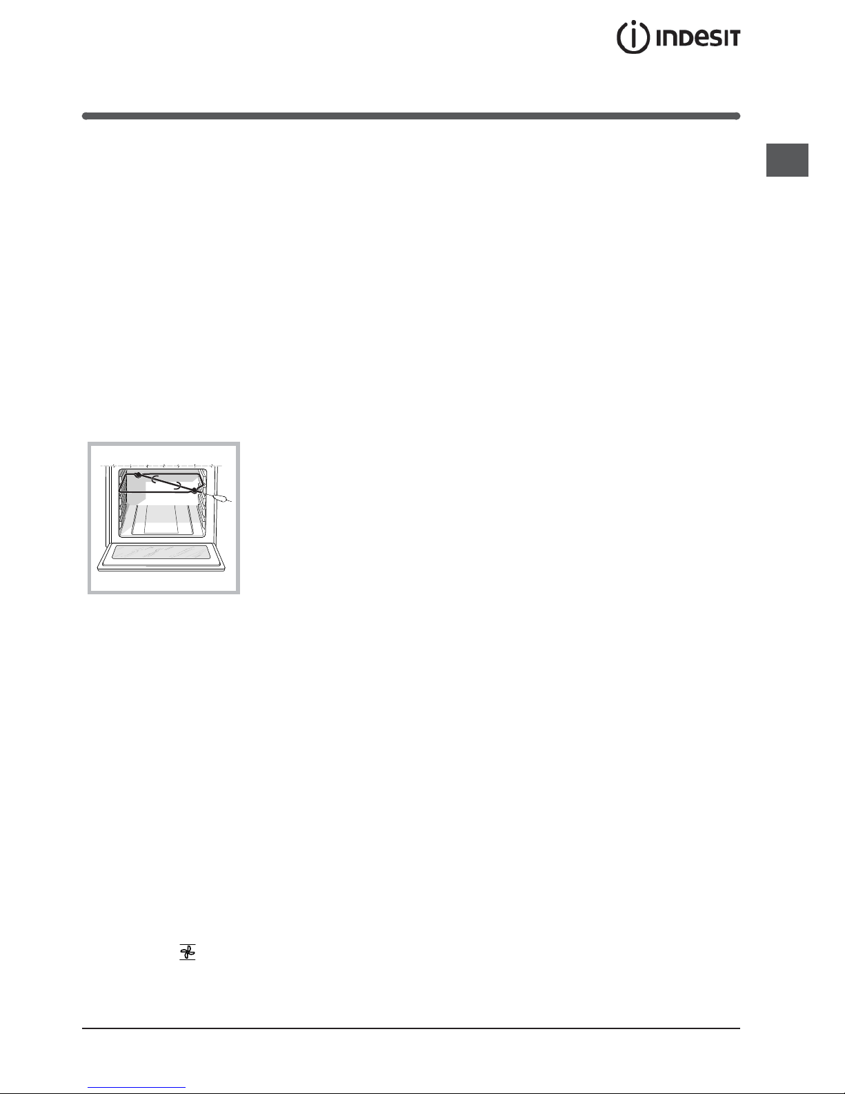
Rotisserie
To activate the rotisserie
function (see diagram)
proceed as follows:
1. Place the dripping pan
in position 1.
2. Place the rotisserie
support in position 4 and
insert the spit in the hole
provided on the back
panel of the oven.
3. Activate the rotisserie
by selecting
with the SELECTOR knob.
Practical advice on using the electric
hotplates
To avoid heat loss and damage to the hotplates use
pans with a flat base, whose diameter is no less than
that of the hotplate itself.
! Before using the hotplates for the first time, you should
heat them at maximum temperature for approximately
4 minutes, without placing any pans on them. During
this initial stage, their protective coating hardens and
reaches its maximum resistance.
Practical cooking advice
Cooking on several shelves simultaneously
If it is necessary to use two racks, use the FAN
ASSITED mode
, as this is the only cooking mode
suited to this type of cooking. We also recommend that:
• Positions 1 and 5 are not used. This is because
excessive direct heat can burn temperature sensitive
foods.

10
GB
The time may be displayed by pressing the button,
and the symbol indicates that the timer function has
been set. After approximately 7 seconds, the display will
automatically revert to the timer.
Cancelling a time that has already been set
Press the - button until the display shows 0:00.
Adjusting the buzzer volume
After selecting and confirming the clock settings, use
the - button to adjust the volume of the alarm buzzer.
GB
11
Oven cooking advice table
Selector knob
setting
Food to be cooked Weight
(in kg)
Cooking rack
position from
bottom
Preheating time
(minutes)
Thermostat
knob
setting
Cooking
time
(minutes)
Baking
Tarts
Fruit cakes
Plum cake
Sponge cake
Stuffed pancakes (on 2
racks)
Small cakes (on 2 racks)
Cheese puffs (on 2
racks)
Cream puffs (on 3 racks)
Biscuits (on 3 racks)
Meringues (on 3 racks)
0.5
1
0.7
0.5
1.2
0.6
0.4
0.7
0.7
0.5
3
2/3
3
3
2-4
2-4
2-4
1-3-5
1-3-5
1-3-5
15
15
15
15
15
15
15
15
15
15
180
180
180
160
200
190
210
180
180
90
20-30
40-45
40-50
25-30
30-35
20-25
15-20
20-25
20-25
180
Convection
Duck
Roast veal or beef
Pork roast
Biscuits (short pastry)
Tarts
1
1
1
1
3
3
3
3
3
15
15
15
15
15
200
200
200
180
180
65-75
70-75
70-80
15-20
30-35
Fan assisted
Pizza (on 2 racks)
Lasagne
Lamb
Roast chicken +
potatoes Mackerel
Plum-cake
Cream puffs (on 2 racks)
Biscuits (on 2 racks)
Sponge cake (on 1 rack)
Sponge cake (on 2
racks)
Savoury pies
1
1
1
1
1
1
0.5
0.5
0.5
1.0
1.5
2-4
3
2
2-4
2
2
2-4
2-4
2
2-4
3
15
10
10
10
10
10
10
10
10
10
15
220
200
180
180
180
170
190
180
170
170
200
15-20
30-35
50-60
60-75
30-35
40-50
20-25
10-15
15-20
20-25
25-30
Top Oven
Browning food to perfect
cooking
- 3/4 15 220 -
Grill
Soles and cuttlefish
Squid and prawn
kebabs
Cod filet
Grilled vegetables
Veal steak
Cutlets
Hamburgers
Mackerels
Toasted sandwiches
1
1
1
1
1
1
1
1
n.° 4
4
4
4
3/4
4
4
4
4
4
5
5
5
5
5
5
5
5
5
Max
Max
Max
Max
Max
Max
Max
Max
Max
8-10
6-8
10
10-15
15-20
15-20
7-10
15-20
2-3
Fan assisted
grill
Grilled chicken
Cuttlefish
1.5
1.5
3
3
5
5
200
200
55-60
30-35
!
cooking times are approximate and may vary according to personal taste. When cooking using the grill or fan
assisted grill, the dripping pan must always be placed on the 1st oven rack from the bottom.
 Loading...