

Page 1

Mode d’emploi
FR
Français, 1
K3M1S/FR
KN3M1S/FR
GB
English,13
CUISINIERE
FR
Sommaire
Installation, 2-5
Positionnement et nivellement
Raccordement électrique
Raccordement gaz
Adaptation aux différents types de gaz
Caractéristiques techniques
Tableau Caractéristiques des brûleurs et des
injecteurs
Description de l’appareil, 6
Vue d’ensemble
Tableau de bord
Mise en marche et utilisation,7-10
Utilisation du plan de cuisson
Mise en marche du four
Programmes de cuisson
Conseils pratiques pour l’utilisation des plaques
électriques
Conseils de cuisson
Tableau de cuisson au four
Précautions et conseils, 11
Sécurité générale
Mise au rebut
Economies et respect de l’environnement
Nettoyage et entretien, 12
Mise hors tension
Nettoyage de l’appareil
Remplacement de l’ampoule d’éclairage du four
Entretien robinets gaz
Assistance
Page 2
Installation
FR
! Conservez ce mode d’emploi pour pouvoir le
consulter à tout moment. En cas de vente, de cession
ou de déménagement, veillez à ce qu’il suive
l’appareil.
! Lisez attentivement les instructions : elles
contiennent des conseils importants sur l’installation,
l’utilisation et la sécurité de votre appareil.
! L’installation de l’appareil doit être effectuée par un
professionnel du secteur conformément aux
instructions du fabricant.
! N’importe quelle opération de réglage, d’entretien,
etc., doit être effectuée après avoir débranché la prise
de la cuisinière.
Conditions réglementaires d’installation
Le raccordement gaz devra être fait par un
professionnel qualifié qui assurera la bonne
alimentation en gaz et le meilleur réglage de la
combustion des brûleurs. Ces opérations
d’installation, quoique simples, sont délicates et
primordiales pour que votre cuisinière vous rende le
meilleur service. L’installation doit être effectuée
conformément aux textes réglementaires et règles de
l’art en vigueur, notamment:
• Arrêté du 2 août 1977. Règles techniques et de
sécurité applicables aux installations de gaz
combustibles et d’hydro-carbures liquéfiés situées
à l’intérieur des bâtiments d’habitation et de leur
dépendances.
• Norme DTU P45-204. Installations de gaz
(anciennement DTU n° 61-1-installations de gaz Avril 1982 + additif n°1 Juillet 1984).
• Règlement sanitaire départemental.
pièces voisines (voir figure B) – à condition qu’il ne
s’agisse pas de parties communes du bâtiment, de
chambres à coucher ou de locaux à risque d’incendie
– équipées d’un conduit d’aération avec l’extérieur
comme décrit plus haut.
Local adjacent Local à ventiler
A B
A
Ouverture de ventilation
pour l’air comburant
! Après une utilisation prolongée de l’appareil, il est
conseillé d’ouvrir une fenêtre ou d’augmenter la
vitesse de ventilateurs éventuels.
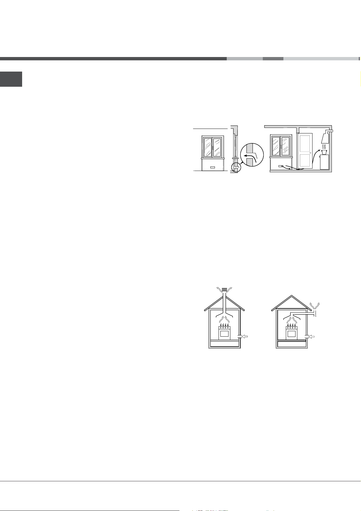
Evacuation des fumées de combustion
La pièce doit prévoir un système d’évacuation vers
l’extérieur des fumées de combustion réalisé au
moyen d’une hotte reliée à une cheminée à tirage
naturel ou par ventilateur électrique qui entre
automatiquement en fonction dès qu’on allume
l’appareil (voir figures).
Agrandissement de la
fissure entre la porte et
le sol
Aération des locaux
L’appareil doit être installé dans des locaux qui sont
aérés en permanence, selon les prescriptions des
Normes en vigueur dans le pays d’installation. Il est
indispensable que la pièce où l’appareil est installé
dispose d’une quantité d’air égale à la quantité d’air
comburant nécessaire à une bonne combustion du
gaz (le flux d’air doit être d’au moins 3 m
puissance installée).
Les prises d’air, protégées par des grilles, doivent
disposer d’un conduit d’au moins 2 cm2 de section
utile et dans une position qui leur évite tout risque
d’être bouchées accidentellement, même
partiellement (voir figure A).
Ces ouvertures doivent être agrandies de 100%
(surface minimale 2 cm2) en cas d’appareils
dépourvus du dispositif de sécurité de flamme et
quand l’afflux de l’air provient de manière indirecte de
22
2
22
3
/h par kW de
Evacuation
directement à
l’extérieur
! Les gaz de pétrole liquéfiés, plus lourds que l’air, se
déposent et stagnent dans le bas. Les locaux qui
contiennent des bouteilles de G.P.L doivent donc
prévoir des ouvertures vers l’extérieur afin de permettre
l’évacuation du gaz par le bas en cas de fuites
accidentelles. Ne pas installer ou entreposer de
bouteilles de GPL, vides ou partiellement pleines, dans
des locaux qui se trouvent en sous-sol (caves etc.). Ne
gardez dans la pièce que la bouteille que vous êtes en
train d’utiliser, loin de sources de chaleur (fours, feux
de bois, poêles etc.) qui pourraient amener sa
température à plus de 50°C.
Evacuation par cheminée ou
conduit de fumée ramifié (réservé
aux appareils de cuisson)
Page 3

Positionnement et nivellement
! L’appareil peut être installé à côté de meubles dont
la hauteur ne dépasse pas celle du plan de cuisson.
! Assurez-vous que le mur en contact avec la paroi
arrière de l’appareil est réalisée en matériel ignifuge
résistant à la chaleur (T 90°C).
Pour une installation correcte :
• installez cet appareil dans une cuisine, une salle à
manger ou un studio (jamais dans une salle de
bains);
• si le plan de cuisson de la cuisinière dépasse le
plan de travail des meubles, ces derniers doivent
être placés à au moins 200 mm de l’appareil;
• si la cuisinière est
HOOD
Min. mm.
600
mm.
420
Min.
420
Min. mm.
• ne placez pas de rideaux derrière la cuisinière ou
sur ses côtés à moins de 200 mm de distance;
• pour l’installation de hottes, conformez-vous aux
instructions de leur notice d’emploi.
installée sous un
élément suspendu, il
faut que ce dernier soit
placé à au moins 420mm
de distance du plan. Il
mm. with hood
mm. without hood
650
700
faut prévoir une distance
min.
min.
de 700mm si les
éléments suspendus sont
inflammables (
);
figure
voir
intercaler entre l’appareil et le réseau un interrupteur à
coupure omnipolaire ayant au moins 3 mm
d’écartement entre les contacts, dimensionné à la
charge et conforme aux normes NFC 15-100 (le fil de
terre ne doit pas être interrompu par l’interrupteur). Le
câble d’alimentation ne doit atteindre, en aucun point,
des températures dépassant de 50°C la température
ambiante.
Avant de procéder au branchement, assurez-vous que :
• la prise est bien munie d’une terre conforme à la loi;
• la prise est bien apte à supporter la puissance
maximale de l’appareil, indiquée sur la plaquette
signalétique;
• la tension d’alimentation est bien comprise entre les
valeurs indiquées sur la plaquette signalétique;
• la prise est bien compatible avec la fiche de
l’appareil. Si ce n’est pas le cas, remplacez la prise
ou la fiche, n’utilisez ni rallonges ni prises multiples.
! Après installation de l’appareil, le câble électrique et
la prise de courant doivent être facilement
accessibles
! Le câble ne doit être ni plié ni excessivement écrasé.
! Le câble doit être contrôlé périodiquement et ne
peut être remplacé que par un technicien agréé.
! Nous déclinons toute responsabilité en cas de
non respect des normes énumérées ci-dessus.
Raccordement gaz
FR
Nivellement
Pour mettre l’appareil bien à
plat, vissez les pieds de
réglage fournis aux
emplacements prévus aux
coins à la base de la cuisinière
(voir figure).
Montage des pieds* par
encastrement sous la base.
Raccordement électrique
Montez sur le câble une prise normalisée pour la
charge indiquée sur l’étiquette des caractéristiques
(
voir tableau des caractéristiques techniques
En cas de raccordement direct au réseau, il faut
).
Pour raccorder l’appareil au réseau de distribution du
gaz ou à la bouteille de gaz utilisez un tuyau flexible
en caoutchouc ou en acier, conformément à la
réglementation en vigueur. Assurez-vous auparavant
que l’appareil est bien réglé pour le type de gaz
d’alimentation utilisé (
autrement voir ci-dessous
voir étiquette sur le couvercle :
). Si l’alimentation s’effectue
avec du gaz liquide en bouteille, utilisez des
régulateurs de pression conformes à la
réglementation en vigueur dans le pays. Pour
simplifier le raccordement, l’alimentation du gaz est
orientable latéralement* : inversez l’about annelé avec
le bouchon de fermeture et remplacez le joint
d’étanchéité (
fourni avec l’appareil
).
! Pour un fonctionnement en toute sécurité, pour un
meilleur emploi de l’énergie et une plus longue durée
de vie de l’appareil, vérifiez que la pression
d’alimentation respecte bien les valeurs indiquées
dans le tableau Caractéristiques des brûleurs et des
injecteurs (voir ci-dessous).
*N’existe que sur certains modèles
33
3
33
Page 4
FR
Raccordement gaz par tuyau flexible en caoutchouc
Assurez-vous que le tuyau est bien conforme aux
normes applicables dans le pays d’installation. Le
tuyau doit avoir un diamètre intérieur de : 8 mm en cas
d’alimentation au gaz liquide; 15 mm en cas
d’alimentation au gaz naturel.
Après avoir effectué le raccordement, assurez-vous
que le tuyau :
• ne touche en aucun point à des parties pouvant
atteindre plus de 50°C;
• ne soit pas soumis à traction ou torsion et ne
présente pas de pliures ou étranglements;
• ne risque pas d’entrer en contact avec des corps
tranchants, des arêtes vives, des parties mobiles et
ne soit pas écrasé;
• puisse être facilement contrôlable sur toute sa
longueur pour vérifier son état de conservation;
• ait moins de 1500mm de long;
• soit bien fixé à ses deux extrémités à l’aide de
bagues de serrage conformes à la réglementation
en vigueur dans le pays.
! Si une ou plusieurs de ces conditions ne peuvent
être remplies ou que la cuisinière est installée dans
des conditions de classe 2 – sous-classe 1 (appareil
encastré entre deux meubles), il faut utiliser un tuyau
flexible en acier (
voir ci-dessous
).
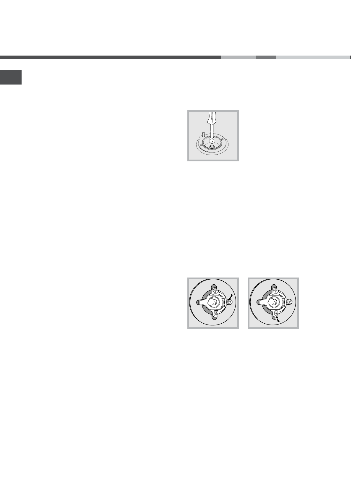
Adaptation du plan de cuisson
Remplacement des injecteurs des brûleurs du plan de
cuisson:
1.enlevez les grilles du plan de cuisson et sortez les
brûleurs de leur logement;
2. dévissez les injecteurs à
l’aide d’une clé à tube de 7mm
(voir figure), et remplacez-les
par les injecteurs adaptés au
nouveau type de gaz (voir
tableau Caractéristiques des
brûleurs et des injecteurs) ;
3.remontez les différentes parties en effectuant les
opérations dans le sens inverse.
Réglage des minima des brûleurs du plan de
cuisson :
1.placez le robinet sur la position minimum;
2.enlevez le bouton et tournez la vis de réglage
positionnée à l’intérieur ou sur le côté de la tige du
robinet jusqu’à obtenir une petite flamme régulière;
! En cas de gaz liquides, il faut visser à fond la vis de
réglage ;
3.vérifiez si, en tournant rapidement le robinet du
maximum au minimum, le brûleur ne s’éteint pas.
! Les brûleurs du plan de cuisson ne nécessitent pas
de réglage de l’air primaire.
Raccordement gaz par tuyau flexible en acier inox,
à paroi continue avec raccords filetés
Assurez-vous que le tuyau et les joints sont bien
conformes aux normes applicables dans le pays
d’installation.
Pour installer le tuyau, enlevez l’about annelé équipant
l’appareil (le raccord d’entrée du gaz à l’appareil est
fileté 1/2 gaz mâle cylindrique).
! Procédez au raccordement de manière à ce que la
longueur du tuyau ne dépasse pas 2 mètres
d’extension maximale. Veillez à ce que le tuyau ne
soit pas écrasé et ne touche en aucun point à des
parties mobiles.
Vérification de l’étanchéité
Une fois l’installation terminée, vérifiez l’étanchéité de
tous les raccords en utilisant une solution
savonneuse, n’utilisez jamais de flamme.
Adaptation aux différents types de gaz
L’appareil peut être adapté à un type de gaz autre
que celui pour le quel il a été conçu (indiqué sur
l’étiquette de réglage sur le couvercle).
44
4
44
Page 5
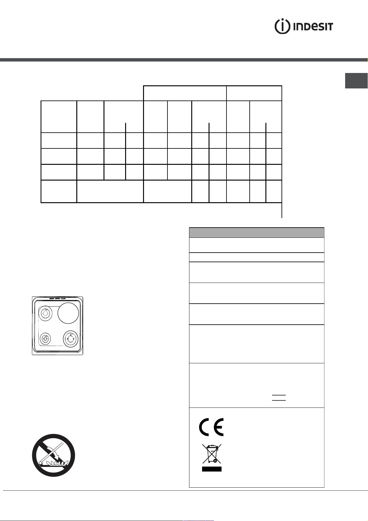
Tableau Caractéristiques des brûleurs et des injecteurs
Tableau 1 Gaz liquide Gaz naturel
FR
Brûleur Diamètre Puissance
thermique
Bipasse
1/100
injecteur
1/100
débit*
g/h
injecteur
1/100
kW (p.c.s.*)
(mm) Nomin. Réd. (mm) (mm) *** ** (mm) G20 G25
Rapide
(Grand)(R)
Semi Rapide
(Moyen)(S)
Auxiliaire
(Petit)(A)
Pressions
d'alimentation
100 3,00 0,7 41 87 218 214 128 286 332
75 1,90 0,4 30 70 138 136 104 181 210
51 1,00 0,4 30 52 73 71 76 95 111
20
35
37
25
45
Nominale (mbar)
Minimum (mbar)
Maximum (mbar)
28-30
(1) Uniquement pour la France, voir la plaquette des caractéristiques de l'appareil . Pour le passage au
gaz à air propané, commandez le kit injecteurs à un Service Après-vente Indesit Company.
* A 15°C et 1013 mbar-gaz sec
** Propane P.C.S. = 50,37 MJ/Kg
*** Butane P.C.S. = 49,47 MJ/Kg
Naturel G20 P.C.S. = 37,78 MJ/m3
Naturel G25 P.C.S. = 32,49 MJ/m3
Ø180
S
R
A
K3M1S/FR
KN3M1S/FR
CARACTERISTIQUES TECHNIQUES
Dimensions du
four HxLxP
Volume
Dimensions
utiles du tiroir
chauffe-plats
Tension et
fréquence
d'alimentation :
Plaque de
cuisson
électrique:
Brûleurs
ETIQUETTE
ENERGIE
34x39x44 cm
l 58
largeur 42 cm
profondeur 44 cm
hauteur 18 cm
voir plaquette signalétique
Rapid Ø 180 mm: 2000 W
adaptables à n'importe quel type
de gaz parmi ceux indiqués sur
l'étiquette collée à l'intérieur du
portillon ou sur la paroi intérieure
gauche (visible après avoir sorti
le tiroir chauffe-plats).
Directive 2002/40/CE sur
l’étiquette d es fours é lectri ques
Norme EN 50304
Consommation énergie déclarée
pour Classe convection naturelle
fonction four : Statique
20
17
25
débit*
l/h
25
20
30
ATTENTION! Le couvercle en verre
peut se casser s’il est chauffé. Il faut
éteindre tous les brûleurs et les
plaques électriques avant de le fermer.
Directives Communautaires:
2006/95/EC du 12/12/06 (Basse
Tension) et modifications
successives - 2004/108/EC du
15/12/04 (Compatibilité
Electromagnétique) et
modifications successives 2009/142/EC du 30/11/09 (Gaz) et
modifications successives
93/68/EC du 22/07/93 et
modifications successives 2002/96/EC.
1275/2008 (Stand-by/ Off mode)
55
5
55
Page 6

Description de l’appareil
FR
Vue d’ensemble
Brûleur à gaz
Grille du plan de cuisson
Tableau de bord
Support GRILLE
Support LECHEFRITE
Pied de réglage
Tableau de bord
Plaque électrique
Plateau du plan de cuisson
GLISSIERES de
coulissement
niveau 5
niveau 4
niveau 3
niveau 2
niveau 1
Pied de réglage
Bougie d’allumage des
BRÛLEURS GAZ*
Bougie d’allumage des
BRÛLEURS GAZ*
66
6
66
Boutons BRULEURS/
plaque électrique
Boutons BRULEURS/
plaque électrique
du plan de cuisson
du plan de cuisson
Page 7
Mise en marche et
X
C
utilisation
Utilisation du plan de cuisson
Allumage des brûleurs
Un petit cercle plein près de chaque bouton
BRULEUR indique le brûleur associé à ce dernier.
Pour allumer un brûleur du plan de cuisson :
1. approchez une flamme ou un allume-gaz ;
2. poussez sur le bouton du BRULEUR tout en le
tournant dans le sens inverse des aiguilles d’une
montre jusqu’au symbole grande flamme E.
3. pour régler la puissance de la flamme souhaitée,
tournez le bouton BRULEUR dans le sens inverse
des aiguilles d’une montre : sur la position
minimum C, sur la position maximum E ou sur une
position intermédiaire.
Si l'appareil est équipé
d'un allumage
électronique*
d'abord appuyer sur la
touche d'allumage,
repérée par le symbole
correspondant
pousser à fond et tourner
en même temps dans le
sens inverse des aiguilles d'une montre le bouton
BRULEUR pour l'amener en face du symbole grande
flamme, jusqu'à l'allumage.
! En cas d’extinction accidentelle des flammes,
éteignez le brûleur et attendez au moins 1 minute
avant de tenter de rallumer.
Pour éteindre le brûleur, tournez le bouton jusqu’à la
position d’arrêt
Si l’appareil est équipé d’un dispositif de sécurité*
de flamme (C), pousser sur le bouton BRULEUR
pendant 2-3 secondes pour garder la flamme
allumée et pour activer le dispositif.
Plaques électriques*
Pour procéder au réglage, tournez la manette
correspondante dans le sens des aiguilles d’une
montre ou dans le sens inverse en choisissant une
des 6 positions possibles :
Position Plaque normale ou rapide
0 Eteint
1 Poissance minimum
2 - 5
6 Poissance maximum
.
Poissance intermédiaires
(X)
il faut
, puis
Toute position de la manette autre que la position
“éteint” entraîne l’allumage du voyant de
fonctionnement.
Conseils pratiques pour l’utilisation des brûleurs
Pour un meilleur rendement des brûleurs et une
moindre consommation de gaz, utilisez des
casseroles à fond plat, munies de couvercle et d’un
diamètre adapté au brûleur:
Brûleur ø Diamètre récipients (cm)
Rapide (R) 24 26
Semi-Rapide (S) 16 20
Auxi liaire (A) 10 14
Pour distinguer le type de brûleur reportez-vous aux
dessins figurant dans le paragraphe
"Caractéristiques des brûleurs et des injecteurs"
! Pour les modèles équipés d'une grille de réduction,
n'utilisez cette dernière que pour le brûleur auxiliaire
quand vous utilisez des casseroles ayant moins de
12 cm de diamètre.
Mise en marche du four
! Lors de son premier allumage, faire fonctionner le
four à vide, porte fermée, pendant au moins une
heure en réglant la température à son maximum.
Puis éteindre le four, ouvrir la porte et aérer la pièce.
L’odeur qui se dégage est due à l’évaporation des
produits utilisés pour protéger le four.
! Avant toute utilisation, vous devez impérativement
enlever les films plastiques situés sur les côtés de
l’appareil
! Ne jamais poser d’objets à même la sole du four,
l’émail risque de s’abîmer. N’utiliser la position 1 du
four qu’en cas de cuissons au tournebroche.
1. Pour sélectionner le programme de cuisson
souhaité, tourner le bouton PROGRAMMES.
2. Choisir la température conseillée pour ce
programme ou celle qu’on préfère à l’aide du bouton
THERMOSTAT.
Un tableau de cuisson sert de guide et indique
notamment les températures conseillées pour
plusieurs préparations culinaires (
cuisson au four
).
voir tableau
FR
* N’existe que sur certains modèles
77
7
77
Page 8

FR
En cours de cuisson, on peut à tout moment :
• modifier le programme de cuisson à l’aide du
bouton PROGRAMMES;
• modifier la température à l’aide du bouton
THERMOSTAT ;
• programmer la durée et l’heure de fin de cuisson
(
voir ci-dessous
• interrompre la cuisson en ramenant le bouton
PROGRAMMES sur “0”.
! Il faut toujours placer les plats sur la grille fournie
avec l’appareil.
Voyant THERMOSTAT
Allumé, il signale la montée en chaleur du four. Il
s’éteint dès que la température sélectionnée est
atteinte. Le voyant s’allume et s’éteint tour à tour
pour indiquer que le thermostat fonctionne et
maintient la température au degré près.
Eclairage du four
Pour l’allumer, amener le bouton PROGRAMMES sur
une position autre que la position “0”. Il reste allumé
tant que le four est en marche. Si on tourne le
bouton sur
aucune résistance.
);
, la lampe s’allume sans activer
Programmes de cuisson
! Pour tous les programmes il est possible de
sélectionner une température comprise entre 50°C et
MAX., sauf pour le programme GRIL, pour lequel il
est préconisé de sélectionner MAX.
Programme Four Statique
Mise en marche des résistances de voûte et de
sole. Pour cette cuisson traditionnelle mieux vaut
cuire sur un seul niveau : la cuisson sur plusieurs
niveaux entraînerait une mauvaise distribution de la
chaleur.
Programme Pâtisserie
permet pas d’atteindre une température maximum à
l’intérieur du four (250°C), il est par conséquent
déconseillé de cuire en maintenant longuement le
four dans cette position à moins qu’il ne s’agisse de
gâteaux qui exigent des températures inférieures ou
égales à 180°C.
Programme Résistance de voûte
Mise en marche de la résistance de voûte. La
température plutôt élevée et directe du gril permet
de saisir immédiatement les viandes évitant ainsi
qu’elles ne durcissent en perdant leur jus.
Programme Grill
Mise en marche de la résistance de voûte et du
tournebroche. La cuisson au gril est particulièrement
recommandée pour les plats qui exigent une
température élevée à leur surface : côtes de veau et
de bœuf, entrecôtes, filet, hamburgers, etc...
! Les cuissons Grill et Résistance de voûte doivent avoir
lieu porte fermée.
Tiroir dessous de four*
Vous pouvez utiliser le
tiroir situé en dessous
du four pour ranger vos
poêles et vos
accessoires de cuisine.
Quand le four est
branché, vous pouvez
aussi vous en servir
pour garder vos plats au
chaud. Le tiroir s’ouvre
vers le bas.
Attention Attention
Attention : n’y déposez pas de matériel
Attention Attention
inflammable.
! Les surfaces intérieures du tiroir (s'il y en a un)
peuvent devenir chaudes.
Attention: Attention:
Attention: ne placez jamais de récipients
Attention: Attention:
bouillants, de mets chauds ou du matériel
inflammable à l'intérieur du tiroir chauffe-plats.
L’élément chauffant inférieur est branché. Cette
position est conseillée pour parfaire la cuisson
d’aliments (placés dans des plats à rôti) qui sont
déjà bien cuits à la surface mais encore mous à
l’intérieur ou pour des gâteaux garnis de fruits ou de
confiture qui ont besoin de se colorer modérément à
leur surface. A remarquer que cette fonction ne
*N’existe que sur certains modèles
88
8
88
Conseils pratiques pour l’utilisation des
plaques électriques
Pour éviter toute déperdition de chaleur et ne pas
endommager la plaque, il est conseillé d’utiliser des
casseroles à fond plat n’ayant pas un plus petit
diamètre que celui de la plaque.
Page 9

Position Plaque normale ou rapide
0
1 Cuisson de légumes verts, poissons
2
Eteint
Cuisson de pommes de terre (à la
vapeur) soupes, pois chiches, haricots
Conseils de cuisson
FR
! En cas de cuisson en mode GRIL, placer la
lèchefrite au gradin 1 pour récupérer les jus de
cuisson.
GRIL
3
4 Rôtir (moyen)
5 Rôtir (fort)
6
! Avant d’utiliser leos plaques de cuisson pour la
première fois, les faire chauffer pendant 4 minutes à
leur température maximum sans casserole. Au cours
de cette phase initiale, le revêtement protecteur
durcit et atteint sa résistance maximum.
Pour continuer la cuisson de grandes
quantités d'aliments, minestrone
Rissoler ou rejoindre l'ébullition en peu
de temps
• Placer la grille au gradin 3 ou 4, enfourner les
plats au milieu de la grille.
• Nous conseillons de sélectionner le niveau
d’énergie maximum. Ne pas s’inquiéter si la
résistance de voûte n’est pas allumée en
permanence: son fonctionnement est contrôlé par
un thermostat.
PIZZA
• Utiliser un plat en aluminium léger et l’enfourner
sur la grille du four.
En cas d’utilisation du plateau émaillé, le temps
de cuisson sera plus long et la pizza beaucoup
moins croustillante.
• Si les pizzas sont bien garnies, n’ajouter la
mozzarelle qu’à mi-cuisson.
*N’existe que sur certains modèles
99
9
99
Page 10

FR
Tableau de cuisson
Position
sélecteur
1 Statique -
Tra ditionnel
2 Four
Pâtisserie
3 Résistance
de voûte
Aliments à cuire Poids
(Kg)
Canard
Rôti de veau ou de buf
Rôti de porc
Biscuits (pâte brisée)
Tartes
Lasagnes
Agneau
Maquereau
Plum-cake
Choux
Génoise
Quiches
Gâteaux levés
Tartes
Gâteaux aux fruits
Brioches
Pour parfaire la cuisson - 3/4 15 220 -
1
1
1
1
1
1
1
1
0.3
0.5
1.5
0,5
1
1
0,5
Position
gradins en
partant du
bas
3
3
3
3
3
3
2
2
2
3
3
3
3
3
3
3
Temps de
préchauffage
(minutes)
15
15
15
15
15
10
10
10
10
10
10
15
15
15
15
15
Position
sélecteur de
températures
200
200
200
180
180
190
180
180
170
180
170
200
160
180
180
160
Temps de
cuisson
(minutes)
65-75
70-75
70-80
15-20
30-35
35-40
50-60
30-35
40-50
30-35
20-25
30-35
30-40
35-40
50-60
25-30
4 Gril
N.B. : les temps de cuisson sont purement indicatifs et peuvent être modifiés selon les goûts de chacun. En cas de
cuisson au gril, placez toujours la lèchefrite sur le 1er gradin en partant du bas.
Soles et seiches
Brochettes de calmars et
crevettes
Tranches de colin
Légumes grillés
Côte de veau
Côtelettes
Hamburgers
Maquereaux
Croque-monsieur
Avec tournebroche (sur
certains modèles)
Veau à la broche
Poulet à la broche
Agneau à la broche
1
1
1
1
1
1
1
1
n.° 4
1.0
1.5
1.0
4
4
4
3/4
4
4
4
4
4
5
5
5
5
5
5
5
5
5
-
-
-
5
5
5
Max
Max
Max
Max
Max
Max
Max
Max
Max
Max
Max
Max
8-10
6-8
10
10-15
15-20
15-20
7-10
15-20
2-3
80-90
70-80
70-80
1010
10
1010
Page 11

Précautions et conseils
! Cet appareil a été conçu et fabriqué conformément
aux normes internationales de sécurité.
Ces conseils sont fournis pour des raisons de sécurité
et doivent être lus attentivement.
Sécurité générale
• Cet appareil a été conçu pour un usage familial, de
type non professionnel.
• Cet appareil ne doit pas être installé en extérieur,
même dans un endroit abrité, il est en effet très
dangereux de le laisser exposé à la pluie et aux
orages.
• Ne touchez pas à l’appareil si vous êtes pieds
nus ou si vous avez les mains ou les pieds
mouillés ou humides.
• Cet appareil a été conçu pour cuire des aliments
et pour être utilisé par des adultes conformément
aux instructions fournies par cette notice,
applicables à tous les pays dont les symboles
figurent au début de la notice. .
• Cette notice concerne un appareil classe 1 (libre
pose) ou classe 2 - sous-classe 1 (encastré entre
deux meubles).
• Eloignez les enfants.
• Evitez que le cordon d’alimentation d’autres petits
électroménagers touche à des parties chaudes de
l’appareil.
• Les orifices ou les fentes d’aération ou d’évacuation
de la chaleur ne doivent pas être bouchés
• Evitez de fermer le couvercle en verre du plan de
cuisson (équipant certains modèles) si les brûleurs
sont allumés ou encore chauds.
• Utilisez toujours des gants de protection pour
enfourner ou sortir des plats du four.
• N’utilisez pas de solutions inflammables (alcool,
essence..) à proximité de l’appareil lorsqu’il est en
marche.
• Ne stockez pas de matériel inflammable dans la
niche de rangement du bas ou dans le four : si
l’appareil était par inadvertance mis en marche, il
pourrait prendre feu.
• Lorsque l’appareil n’est pas utilisé, assurez-vous
que les boutons sont bien sur la position
le robinet du gaz est fermé.
• Ne tirez surtout pas sur le câble pour débrancher
la fiche de la prise de courant.
• N’effectuez aucune opération de nettoyage ou
d’entretien sans avoir auparavant débranché la
fiche de la prise de courant.
• En cas de panne, n’essayez en aucun cas
d’accéder aux mécanismes internes pour tenter
de réparer l’appareil. Faites appel au service
d’assistance.
et que
• Ne posez pas d’objets lourds sur la porte du four
ouverte.
• Cet appareil doit être exclusivement destiné à
l’usage pour lequel il a été conçu. Toute
autre utilisation (telle que le chauffage d’une
pièce, par exemple) est impropre et, en tant
que telle, dangereuse. Le fabricant décline
topute responsabilité en cas de dommages
provoqués par l’usage impropre de
l’appareil.
Mise au rebut
• Mise au rebut du matériel d’emballage :
conformez-vous aux réglementations locales, les
emballages pourront ainsi être recyclés.
• La directive européenne 2002/96/CE relative aux
déchets d’équipements électriques et électroniques
(DEEE), prévoit que les électroménagers ne
peuvent pas être traités comme des déchets
solides urbains normaux. Les appareils usagés
doivent faire l’objet d’une collecte séparée pour
optimiser le taux de récupération et de recyclage
des matériaux qui les composent et empêcher tout
danger pour la santé et pour l’environnement. Le
symbole de la poubelle barrée sur roues est
appliqué sur tous les produits pour rappeler qu’ils
font l’objet d’une collecte sélective.
Les électroménagers usagés pourront être remis au
service de collecte public, déposés dans les
déchetteries communales prévues à cet effet ou, si
la loi du pays le prévoit, repris par les revendeurs
lors de l’achat d’un nouvel appareil de même type.
Tous les principaux fabricants d’électroménagers
s’appliquent à créer et gérer des systèmes de
collecte et d’élimination des appareils usagés.
Economies et respect de
l’environnement
• Pour faire des économies d’électricité, utilisez
autant que possible votre four pendant les heures
creuses.
• Pour vos cuissons au Gratin, nous vous conseillons
de garder la porte du four fermée : Vous obtiendrez
de meilleurs résultats tout en faisant de sensibles
économies d’énergie (10% environ).
• Gardez toujours les joints propres et en bon état
pour qu’ils adhèrent bien à la porte et ne causent
pas de déperditions de chaleur.
FR
1111
11
1111
Page 12

Nettoyage et entretien
FR
Mise hors tension
Avant toute opération de nettoyage ou d’entretien
coupez l’alimentation électrique de l’appareil.
Nettoyage de l’appareil
! Ne nettojez jamais l’appareil avec des nettoyeurs
vapeur ou haute pression.
• Nettoyez l’extérieur émaillé ou inox et les joints en
caoutchouc à l’aide d’une éponge imbibée d’eau
tiède additionnée de savon neutre Si les taches sont
difficiles à enlever, utilisez des produits spéciaux.
Rincez abondamment et essuyez soigneusement.
N’utilisez ni poudres abrasives ni produits corrosifs.
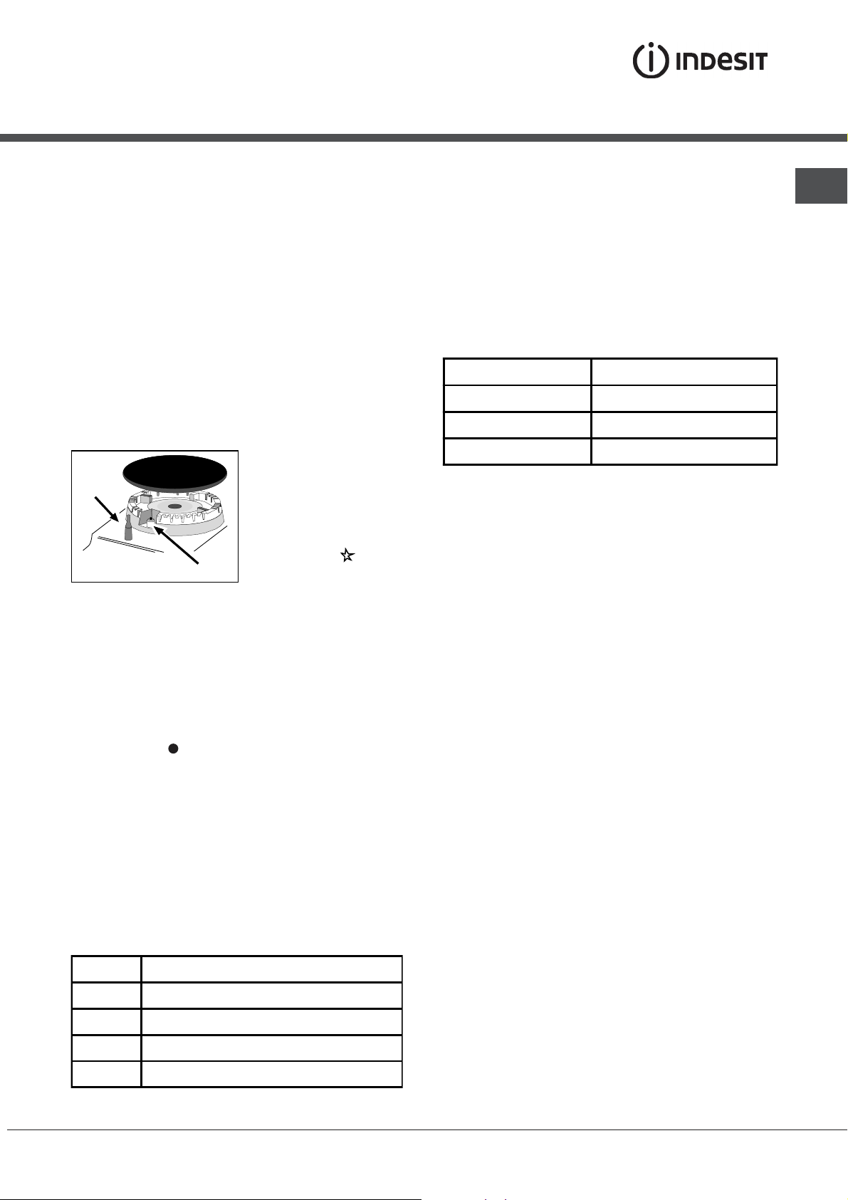
• Les grilles, les chapeaux, les couronnes et les
brûleurs du plan de cuisson sont amovibles et
peuvent ainsi être nettoyés plus facilement.
Lavez-les à l’eau chaude additionnée d’un
détergent non abrasif, éliminez toute incrustation
et attendez qu’ils soient parfaitement secs avant
de les remonter.
• Nettoyez fréquemment l’extrémité des dispositifs
de sécurité* de flamme.
complètement et tirez vers le haut (
! Evitez de refermer le couvercle si les brûleurs sont
allumés ou encore chauds.
Contrôler les joints du four
Contrôlez périodiquement l’état du joint autour de la
porte du four. S’il est abîmé, adressez-vous au service
après-vente le plus proche de votre domicile. Mieux
vaut ne pas utiliser le four tant qu’il n’est pas réparé.
voir figure
).
Remplacement de l’ampoule d’éclairage
du four
1. Débranchez le four,
enlevez le couvercle en verre
du logement de la lampe (
).
figure
2. Dévissez l’ampoule et
remplacez-la par une autre de
même type : tension 230 V, puissance 25 W, culot E
14.
3.Remontez le couvercle et rebranchez le four au
réseau électrique.
voir
Assistance
• Nettoyez l’enceinte du four après toute utilisation,
quand il est encore tiède. Utilisez de l’eau chaude
et du détergent, rincez et séchez avec un chiffon
doux. Evitez tout produit abrasif.
• Nettoyer la vitre de la porte avec des produits non
abrasifs et des éponges non grattantes, essuyer
ensuite avec un chiffon doux. Ne pas utiliser de
matériaux abrasifs ou de racloirs métalliques aiguisés
qui risquent de rayer la surface et de briser le verre.
• Les accessoires peuvent être lavés comme de la
vaisselle courante y compris en lave-vaisselle.
Le couvercle
Pour le nettoyage des
modèles équipés de
couvercle en verre,
utilisez de l’eau tiède.
Evitez tout produit
abrasif. Vous pouvez
déposer le couvercle
pour simplifier le
nettoyage de la zone
arrière du plan de
cuisson : ouvrez-le
Indiquez-lui :
• le modèle de votre appareil (Mod.)
• son numéro de série (S/N)
Ces informations figurent sur la plaquette
signalétique apposée sur votre appareil et/ou sur
son emballage.
Nettoyage automatique du four par catalyse*
Dans certains modèles de four, les parois verticales intérieures sont revêtues
d’un émail poreux dit émail catalytique. Il a pour propriété de détruire les corps
gras sous l’effet de la chaleur. Ceci est possible quand la température des
parois dépasse 170°C.
En fin de cuisson, s’il y a encore des traces de graisse sur les parois
catalytiques, continuez à faire fonctionner le four, à vide, porte fermée, en
amenant le bouton FOUR sur la position MAX, pendant un laps de temps
compris entre 60 et 90 minutes selon le degré de salissure. Vous pouvez
accélérer le dégraissage en nettoyant les projections alimentaires plus
importantes avec un peu d’eau chaude et une brosse souple.
! L’émail catalytique est résistant mais il faut éviter :
de gratter l’émail avec des objets tranchants (couteaux …)
et d’utiliser des détergents ou des produits de nettoyage abrasifs, les propriétés
autonettoyantes de l’émail risqueraient autrement d’être détruites irrémédiablement.
N’existe que sur certains modèles
*
1212
12
1212
Page 13

Operating Instructions
COOKER
FR
Français, 1
K3M1S/FR
KN3M1S/FR
GB
English,13
Contents
GB
Installation, 14-17
Positioning and levelling
Electrical connection
Gas connection
Adapting to different types of gas
Table of burner and nozzle specifications
Table of characteristics
Description of the appliance, 18
Overall view
Control panel
Start-up and use, 19-21
Using the hob
Using the oven
Cooking modes
Practical advice on using the electric hotplates
Practical cooking advice
Oven cooking advice table
Precautions and tips, 22
General safety
Disposal
Respecting and conserving the environment
Care and maintenance, 23
Switching the appliance off
Cleaning the appliance
Replacing the oven light bulb
Gas tap maintenance
Assistance
Page 14

Installation
GB
! Before operating your new appliance please read
this instruction booklet carefully. It contains
important information concerning the safe installation
and operation of the appliance.
! Please keep these operating instructions for future
reference. Make sure that the instructions are kept
with the appliance if it is sold, given away or moved.
! The appliance must be installed by a qualified
professional according to the instructions provided.
! Any necessary adjustment or maintenance must be
performed after the cooker has been disconnected
from the electricity supply.
Room ventilation
The appliance may only be installed in permanentlyventilated rooms, according to current national
legislation. The room in which the appliance is
installed must be ventilated adequately so as to
provide as much air as is needed by the normal gas
combustion process (the flow of air must not be
lower than 2 m
3
/h per kW of installed power).
The air inlets, protected by grilles, should have a
duct with an inner cross section of at least 100 cm
2
and should be positioned so that they are not liable
to even partial obstruction (
see figure A
).
These inlets should be enlarged by 100% - with a
minimum of 200 cm
2
- whenever the surface of the
hob is not equipped with a flame failure safety
device. When the flow of air is provided in an
indirect manner from adjacent rooms (
see figure B
),
provided that these are not communal parts of a
building, areas with increased fire hazards or
bedrooms, the inlets should be fitted with a
ventilation duct leading outside as described above.
AB
Adjacent room Room requiring
ventilation
Disposing of combustion fumes
The disposal of combustion fumes should be
guaranteed using a hood connected to a safe and
efficient natural suction chimney, or using an electric
fan that begins to operate automatically every time
the appliance is switched on (
Fumes channelled
straight outside
see figure
Fumes channelled through
a chimney or branched
flue system reserved for
cooking appliances)
).
! The liquefied petroleum gases are heavier than air
and collect by the floor, therefore all rooms
containing LPG cylinders must have openings
leading outside so that any leaked gas can escape
easily.
LPG cylinders, therefore, whether partially or
completely full, must not be installed or stored in
rooms or storage areas that are below ground level
(cellars, etc.). Only the
cylinder being used should be stored in the room;
this should also be kept well away from sources
of heat (ovens, chimneys, stoves) that may cause
the temperature of the cylinder to rise above 50°C.
Positioning and levelling
! It is possible to install the appliance alongside
cupboards whose height does not exceed that of the
hob surface.
! Make sure that the wall in contact with the back of
the appliance is made from a non-flammable, heatresistant material (T 90°C).
A
Ventilation opening for
comburent air
Increase in the gap between
the door and the flooring
! After prolonged use of the appliance, it is
advisable to open a window or increase the speed of
any fans used.
14
To install the appliance correctly:
• Place it in the kitchen, dining room or the bed-sit
(not in the bathroom).
• If the top of the hob is higher than the cupboards,
the appliance must be installed at least 200 mm
away from them.
• If the cooker is installed underneath a wall cabinet,
there must be a minimum distance of 420 mm
between this cabinet and the top of the hob.
This distance should be increased to 700 mm if
the wall cabinets are flammable (
see figure
).
Page 15

mm.
420
Min.
Levelling
HOOD
Min. mm.
600
• Do not position
blinds behind the
cooker or less than 200
mm away from its
sides.
mm. with hood
420
mm. without hood
• Any hoods must be
650
700
Min. mm.
min.
installed according to
min.
the instructions listed in
the relevant operating
manual.
If it is necessary to level the
appliance, screw the
adjustable feet into the places
provided on each corner of the
base of the cooker (
).
figure
see
The legs* fit into the slots on
the underside of the base of
the cooker.
! Once the appliance has been installed, the power
supply cable and the electrical socket must be
easily accessible.
! The cable must not be bent or compressed.
! The cable must be checked regularly and replaced
by authorised technicians only.
! The manufacturer declines any liability should
these safety measures not be observed.
Gas connection
Connection to the gas network or to the gas cylinder
may be carried out using a flexible rubber or steel
hose, in accordance with current national legislation
and after making sure that the appliance is suited to
the type of gas with which it will be supplied (see the
rating sticker on the cover: if this is not the case
). When using liquid gas from a cylinder, install a
below
pressure regulator which complies with current national
regulations. To make connection easier, the gas
supply may be turned sideways*: reverse the position
of the hose holder with that of the cap and replace the
gasket that is supplied with the appliance.
see
GB
Electrical connection
Install a standardised plug corresponding to the
load indicated on the appliance data plate (
Technical data table
).
The appliance must be directly connected to the mains
using an omnipolar circuit-breaker with a minimum
contact opening of 3 mm installed between the
appliance and the mains. The circuit-breaker must be
suitable for the charge indicated and must comply with
NFC 15-100 regulations (the earthing wire must not be
interrupted by the circuit-breaker). The supply cable
must be positioned so that it does not come into
contact with temperatures higher than 50°C at any point.
Before connecting the appliance to the power
supply, make sure that:
• The appliance is earthed and the plug is compliant
with the law.
• The socket can withstand the maximum power of
the appliance, which is indicated by the data plate.
• The voltage is in the range between the values
indicated on the data plate.
• The socket is compatible with the plug of the
appliance. If the socket is incompatible with the
plug, ask an authorised technician to replace it.
Do not use extension cords or multiple sockets.
* Only available in certain models
see
! Check that the pressure of the gas supply is
consistent with the values indicated in the Table of
burner and nozzle specifications (
see below
). This
will ensure the safe operation and durability of your
appliance while maintaining efficient energy
consumption.
Gas connection using a flexible rubber hose
Make sure that the hose complies with current
national legislation. The internal diameter of the hose
must measure: 8 mm for liquid gas supply; 13 mm
for methane gas supply.
Once the connection has been performed, make
sure that the hose:
• Does not come into contact with any parts that
reach temperatures of over 50°C.
• Is not subject to any pulling or twisting forces and
that it is not kinked or bent.
• Does not come into contact with blades, sharp
corners or moving parts and that it is not
compressed.
• Is easy to inspect along its whole length so that
its condition may be checked.
• Is shorter than 1500 mm.
• Fits firmly into place at both ends, where it will be
fixed using clamps that comply with current
regulations.
15
Page 16

GB
! If one or more of these conditions is not fulfilled or
if the cooker must be installed according to the
conditions listed for class 2 - subclass 1 appliances
(installed between two cupboards), the flexible steel
hose must be used instead (
Connecting a flexible jointless stainless steel pipe
to a threaded attachment
Make sure that the hose and gaskets comply with
current national legislation.
To begin using the hose, remove the hose holder on the
appliance (the gas supply inlet on the appliance is a
cylindrical threaded 1/2 gas male attachment).
! Perform the connection in such a way that the hose
length does not exceed a maximum of 2 metres,
making sure that the hose is not compressed and
does not come into contact with moving parts.
Checking the connection for leaks
When the installation process is complete, check
the hose fittings for leaks using a soapy solution.
Never use a flame.
see below
).
3. While the burner is alight, quickly change the position
of the knob from minimum to maximum and vice versa
several times, checking that the flame is not
extinguished.
! The hob burners do not require primary air adjustment.
Adjusting the gas oven burner’s minimum setting:
1. Light the burner (
2. Turn the knob to the minimum position (MIN) after
it has been in the maximum position (MAX) for
approximately 10 minutes.
3. Remove the knob.
4. Tighten or loosen the adjustment screws on the
outside of the thermostat pin (
flame is small but steady.
! If the appliance is connected to liquid gas, the
adjustment screw must be fastened as tightly as
possible.
5. Turn the knob from the MAX position to the MIN
position quickly or open and shut the oven door,
making sure that the burner is not extinguished.
see Start-up and Use
see figure
).
) until the
Adapting to different types of gas
It is possible to adapt the appliance to a type of gas
other than the default type (this is indicated on the
rating label on the cover).
Adapting the hob
Replacing the nozzles for the hob burners:
1. Remove the hob grids and slide the burners off
their seats.
2. Unscrew the nozzles using a
7 mm socket spanner (
figure
), and replace them with
nozzles suited to the new type
of gas(
see Burner and nozzle
specifications table
3. Replace all the components
by following the above
instructions in reverse.
Adjusting the hob burners’ minimum setting:
1. Turn the tap to the minimum position.
2. Remove the knob and adjust the regulatory
screw, which is positioned inside or next to the tap
pin, until the flame is small but steady.
! If the appliance is connected to a liquid gas
supply, the regulatory screw must be fastened as
tightly as possible.
see
).
16
Page 17

Table of burner and nozzle specifications
Table 1 Liquid gas Natural gas
Burner Diameter
(mm)
Rapid (Large)
(R)
Semi-rapid
(Medium) (S)
Auxiliary
(Small) (A)
Supply
pressure
* At 15°C and 1013 mbar - dry gas
** Propane P.C.S. = 50.37 MJ/kg
*** Butane P.C.S. = 49.47 MJ/kg
Natural P.C.S. = 37.78 MJ/m³
100 3.00 0.70 41 87 218 214 128 286 332
75 1.90 0.40 30 70 138 136 104 181 210
51 1.00 0.40 30 52 73 71 76 95 111
Maximised (mbar)
Thermal power
kW (p.c.s.*)
Nominal Reduced
Nominal (mbar)
Minimal (mbar)
Bypass
1/100
(mm)
Nozzle
1/100
(mm)
Capacity*
g/h
*** **
28-30
20
35
37
25
45
Nozzle
1/100
(mm)
Capacity*
l/h
G20 G25
20
17
25
GB
Ø180
S
R
A
K3M1S/FR
KN3M1S/FR
WARNING! The glass lid canWARNING! The glass lid can
WARNING! The glass lid can
WARNING! The glass lid canWARNING! The glass lid can
break in if it is heated up.break in if it is heated up.
break in if it is heated up.
break in if it is heated up.break in if it is heated up.
Turn off all the burners andTurn off all the burners and
Turn off all the burners and
Turn off all the burners andTurn off all the burners and
the electric plates beforethe electric plates before
the electric plates before
the electric plates beforethe electric plates before
closing the lid.closing the lid.
closing the lid.
closing the lid.closing the lid.
TECHNICAL DATA
Oven dimensions
(HxWxD)
Vol ume
Useful
measurements
relating to the oven
compartment
Bur ner s
Voltage and
frequency
Electric Hotplate
ENERGY LABEL
34x39x44 cm
58 l
width 42 cm
depth 44 cm
height 18 cm
may be adapted for use with any
type of gas shown on the data plate
see data plate
Rapid Ø 180 mm: 2000 W
Directive 2002/ 40/EC on the label
of electric ovens.
Regulation EN 50304
Declared energy consumption for
Natural convection Class –
heating mode
Static
EC Directives: 2006/95/EC dated
12/12/06 (Low Voltage) and
subsequent amendments 2004/108/EC dated 15/12/04
(Electromagnetic Compatibility)
and subsequent amendments 2009/142/EC dated 30/11/09
(Gas)
1275/2008 (Stand-by/ Off mode)
17
Page 18

Description of the
appliance
GB
Overall view
Gas burner
Control panel
DRIPPING PAN
Adjustable foot
Hob grid
GRILL
Glass cover*
Electric Hotplate
Containment surface
for spills
GUIDE RAILS
for the sliding racks
position 5
position 4
position 3
position 2
position 1
Adjustable foot
Control panel
THERMOSTAT
indicator light
GAS BURNER
ignition button*
THERMOSTAT
indicator light
THERMOSTAT
knob
SELECTOR
knob
THERMOSTAT
knob
ACTIVE HOTPLATE
indicator light
Hob BURNER or ELECTRIC HOTPLATE
control knobs
ACTIVE HOTPLATE
indicator light
GAS BURNER
ignition button*
* Only available in certain models.
18
SELECTOR
knob
Hob BURNER or ELECTRIC HOTPLATE
control knobs
Page 19

Start-up and use
Using the hob
Lighting the burners
For each BURNER knob there is a complete ring
showing the strength of the flame for the relevant burner.
To light one of the burners on the hob:
1. Bring a flame or gas lighter close to the burner.
2. Press the BURNER knob and turn it in an
anticlockwise direction so that it is pointing to the
maximum flame setting E.
3. Adjust the intensity of the flame to the desired level
by turning the BURNER knob in an anticlockwise
direction. This may be the minimum setting C, the
maximum setting E or any position in between the two.
If the appliance is fitted with an electronic lighting
device* (
ignition button, marked
X
C
burner is lit.The burner may be extinguished when
the knob is released. If this occurs, repeat the
operation, holding the knob down for a longer period
of time.
! If the flame is accidentally extinguished, switch off
the burner and wait for at least 1 minute before
attempting to relight it.
If the appliance is equipped with a flame failure
safety device*(C), press and hold the BURNER knob
for approximately 2-3 seconds to keep the flame
alight and to activate the device.
with the symbol 1, then
hold the BURNER knob
down and turn it in an
anticlockwise direction,
towards the maximum
flame setting, until the
X
), press the
Practical advice on using the burners
For the burners to work in the most efficient way
possible and to save on the amount of gas
consumed, it is recommended that only pans that
have a lid and a flat base are used. They should
also be suited to the size of the burner:
Burner ø Cookware diameter (cm)
Fast (R) 24 - 26
Semi Fast (S) 16 - 20
Auxiliary (A) 10 - 14
To identify the type of burner, please refer to the
diagrams contained in the “Burner and nozzle
specifications”.
! For models equipped with a reducer grid, the latter
must be used only for the auxiliary burner, when
pans with a diameter of less than 12 cm are used.
Using the oven
! The first time you use your appliance, heat the empty
oven with its door closed at its maximum temperature
for at least half an hour. Ensure that the room is well
ventilated before switching the oven off and opening
the oven door. The appliance may emit a slightly
unpleasant odour caused by protective substances
used during the manufacturing process burning away.
! Before operating the product, remove all plastic
film from the sides of the appliance.
GB
To switch the burner off, turn the knob until it
reaches the stop position •.
Electric hotplates*
The corresponding knob may be turned clockwise or
anti-clockwise and set to six different positions:
Setting Normal or Fast Plate
0 Off
1 Low
2 - 5 Medium
6
High
When the selector knob is in any position other than
the off position, the ‘on’ light comes on.
! Never put objects directly on the bottom of the oven;
this will avoid the enamel coating being damaged.
1. Select the desired cooking mode by turning the
SELECTOR knob.
2. Select the recommended temperature for the
cooking mode or the desired temperature by turning
the THERMOSTAT knob.
A list detailing cooking modes and suggested
cooking temperatures can be found in the relevant
table (
see Oven cooking advice table
During cooking it is always possible to:
• Change the cooking mode by turning the
SELECTOR knob.
• Change the temperature by turning the
THERMOSTAT knob.
Only available in certain models.
*
).
19
Page 20

GB
• Stop cooking by turning the SELECTOR knob to
the “0” position.
! Always place cookware on the rack(s) provided.
THERMOSTAT indicator light
When this is illuminated, the oven is generating
heat. It switches off when the inside of the oven
reaches the selected temperature. At this point the
light illuminates and switches off alternately,
indicating that the thermostat is working and is
maintaining the temperature at a constant level.
Oven light
This is switched on by turning the SELECTOR knob
to any position other than “0”. It remains lit as long
as the oven is operating. By selecting
knob, the light is switched on without any of the
heating elements being activated.
with the
GRILL mode
The top heating element and the rotisserie spit will
be activated. The grill is also highly recommended
for dishes that require a high surface temperature:
beef steaks, veal, rib steak, fillets, hamburgers
etc...
! The GRILL and OVEN TOP cooking modes must be
performed with the oven door shut.
Practical advice on using the electric
hotplates
To avoid heat loss and damage to the hotplates use
pans with a flat base, whose diameter is no less
than that of the hotplate itself.
Setting Normal or Fast Plate
Cooking modes
! A temperature value can be set for all cooking
modes between 50°C and MAX, except for the
GRILL programme, for which only the MAX power
level is recommended.
STATIC OVEN STATIC OVEN
STATIC OVEN mode
STATIC OVEN STATIC OVEN
Both the top and bottom heating elements will come
on. When using this traditional cooking mode, it is
best to use one cooking rack only. If more than one
rack is used, the heat will be distributed in an
uneven manner.
OVEN B OVEN B
OVEN B
OVEN B OVEN B
The lower heating element is activated. This position
is recommended for perfecting the cooking of
dishes (in baking trays) which are already cooked on
the surface but require further cooking in the centre,
or for desserts with a covering of fruit or jam, which
only require moderate colouring on the surface. It
should be noted that this function does not allow the
maximum temperature to be reached inside the oven
(250°C) and it is therefore not recommended that
foods are cooked using only this setting, unless you
are baking cakes (which should be baked at a
temperature of 180°C or lower).
OVEN TOP mode
The top heating element is activated. The extremely
high and direct temperature of the grill makes it
possible to brown the surface of meats and roasts
while locking in the juices to keep them tender.
* Only available in certain models.
OTTOMOTTOM
OTTOM mode
OTTOMOTTOM
0 Off
1 Cooking vegetables, fish
Cooking potatoes (using steam) soups,
2
chickpeas, beans.
Continuing the cooking of large quantities
3
of food, minestrone
4
For roasting (average)
5 For roasting (above average)
For browning and reaching a boil in a
6
short time.
! Before using the hotplates for the first time, you
should heat them at maximum temperature for
approximately 4 minutes, without placing any pans
on them. During this initial stage, their protective
coating hardens and reaches its maximum
resistance.
Lower compartment*
There is a compartment underneath the oven that
may be used to store oven accessories or deep
dishes. To open the
door pull it downwards
(
see figure
! The internal surfaces
of the compartment
(where present) may
become hot.
! Do not place
flammable materials in
the lower oven
compartment.
).
20
Page 21

Practical cooking advice
! In the GRILL cooking mode, place the dripping
pan in position 1 to collect cooking residues (fat
and/or grease).
GRILL
• Insert the rack in position 3 or 4. Place the food in
the centre of the rack.
• We recommend that the power level is set to
maximum. The top heating element is regulated
by a thermostat and may not always operate
constantly.
Oven cooking advice table
PIZZA
• Use a light aluminium pizza pan. Place it on the
rack provided.
For a crispy crust, do not use the dripping pan as
it prevents the crust from forming by extending
the total cooking time.
• If the pizza has a lot of toppings, we recommend
adding the mozzarella cheese on top of the pizza
halfway through the cooking process.
GB
Selector knob
setting
1 Static
2 Bottom
Oven
3 Top Oven
4 Grill
NB: cooking times are approximate and may vary according to personal taste. When cooking using the
dripping pan must always be placed on the 1st oven rack from the bottom.
Food to be cooked Weight
(in kg)
Duck
Roast veal or beef
Pork roast
Biscuits (short pastry)
Tar ts
Lasagne
Lamb
Mackerel
Plum-cake
Cream puffs
Sponge-cake
Savoury pies
Raised Cakes
Tar ts
Fru it cakes
Brioches
Browning food to
perfect cooking
Soles and cuttlefish
Squid and prawn
kebabs
Cod filet
Grilled vegetables
Veal steak
Cutlets
Hamburgers
Mackerels
Toasted sandwiches
With rotisserie (where
present)
Veal on the spit
Chicken on the spit
Lamb on the spit
1
1
1
1
1
1
1
1
0.3
0.5
1.5
0,5
1
1
0,5
- 3/415 220 -
1
1
1
1
1
1
1
1
n.° 4
1.0
1.5
1.0
Cooking rack
position from
bottom
3
3
3
3
3
3
2
2
2
3
3
3
3
3
3
3
4
4
4
3/4
4
4
4
4
4
-
-
-
Preheating time
(minutes)
15
15
15
1
5
15
10
10
10
10
10
10
15
15
15
15
15
5
5
5
5
5
5
5
5
5
5
5
5
Thermostat
knob
setting
200
200
200
180
180
190
180
180
170
180
170
200
160
180
180
160
Max
Max
Max
Max
Max
Max
Max
Max
Max
Max
Max
Max
Cooking
time
(minutes)
65-75
70-75
70-80
15-20
30-35
35-40
50-60
30-35
40-50
30-35
20-25
30-35
30-40
35-40
50-60
25-30
8-10
6-8
10
10-15
15-20
15-20
7-10
15-20
2-3
80-90
70-80
70-80
grill, the
* Only available in certain models.
21
Page 22

Precautions and tips
GB
! This appliance has been designed and manufactured in
compliance with international safety standards.
The following warnings are provided for safety reasons and must
be read carefully.
General safety
• These instructions are only valid for the
countries whose symbols appear in the
manual and on the serial number plate.
• The appliance was designed for domestic use inside the home
and is not intended for commercial or industrial use.
• The appliance must not be installed outdoors, even in covered
areas. It is extremely dangerous to leave the appliance
exposed to rain and storms.
• Do not touch the appliance with bare feet or with wet or damp
hands and feet.
• The appliance must be used by adults only for
the preparation of food, in accordance with the
instructions outlined in this booklet. Any other
use of the appliance (e.g. for heating the room)
constitutes improper use and is dangerous.
The manufacturer may not be held liable for
any damage resulting from improper, incorrect
and unreasonable use of the appliance.
• The instruction booklet accompanies a class 1 (insulated) or
class 2 - subclass 1 (recessed between 2 cupboards)
appliance.
• Keep children away from the oven.
• Make sure that the power supply cables of other electrical
appliances do not come into contact with the hot parts of the
oven.
• The openings used for the ventilation and dispersion of heat
must never be covered.
• Do not close the glass hob cover (selected models only) when
the burners are alight or when they are still hot.
• Always use oven gloves when placing cookware in the oven or
when removing it.
• Do not use flammable liquids (alcohol, petrol, etc...) near the
appliance while it is in use.
• Do not place flammable material in the lower storage
compartment or in the oven itself. If the appliance is switched
on accidentally, it could catch fire.
• Always make sure the knobs are in the • position and that the
gas tap is closed when the appliance is not in use.
• When unplugging the appliance, always pull the plug from the
mains socket; do not pull on the cable.
• Never perform any cleaning or maintenance work without
having disconnected the appliance from the electricity mains.
• If the appliance breaks down, under no circumstances should
you attempt to repair the appliance yourself. Repairs carried
out by inexperienced persons may cause injury or further
malfunctioning of the appliance. Contact Assistance.
• Do not rest heavy objects on the open oven door.
• Do not let children play with the appliance.
• The appliance should not be operated by people (including
children) with reduced physical, sensory or mental capacities,
by inexperienced individuals or by anyone who is not familiar
with the product. These individuals should, at the very least,
be supervised by someone who assumes responsibility for their
safety or receive preliminary instructions relating to the
operation of the appliance.
Disposal
• When disposing of packaging material: observe local
legislation so that the packaging may be reused.
• The European Directive 2002/96/EC relating to Waste
Electrical and Electronic Equipment (WEEE) states that
household appliances should not be disposed of using the
normal solid urban waste cycle. Exhausted appliances should
be collected separately in order to optimise the cost of reusing and recycling the materials inside the machine, while
preventing potential damage to the atmosphere and to public
health. The crossed-out dustbin is marked on all products to
remind the owner of their obligations regarding separated
waste collection.
Exhausted appliances may be collected by the public waste
collection service, taken to suitable collection areas in the
area or, if permitted by current national legislation, they may
be returned to the dealers as part of an exchange deal for a
new equivalent product.
All major manufacturers of household appliances
participate in the creation and organisation of
systems for the collection and disposal of old and
disused appliances.
Respecting and conserving the
environment
• You can help to reduce the peak load of the electricity supply
network companies by using the oven in the hours between
late afternoon and the early hours of the morning.
• Check the door seals regularly and wipe them clean to ensure
they are free of debris so that they adhere properly to the
door, thus avoiding
heat dispersion.
22
Page 23

Care and maintenance
Switching the appliance off
Disconnect your appliance from the electricity supply
before carrying out any work on it.
Cleaning the appliance
! Do not use abrasive or corrosive detergents such as
stain removers, anti-rust products, powder detergents or
sponges with abrasive surfaces: these may scratch the
surface beyond repair.
! Never use steam cleaners or pressure cleaners on the
appliance.
• It is usually sufficient simply to wash the hob using a
damp sponge and dry it with absorbent kitchen roll.
• The stainless steel or enamel-coated external parts and
the rubber seals may be cleaned using a sponge that
has been soaked in lukewarm water and neutral soap.
Use specialised products for the removal of stubborn
stains. After cleaning, rinse well and dry thoroughly. Do
not use abrasive powders or corrosive substances.
• The hob grids, burner caps, flame spreader rings
and the hob burners can be removed
to make cleaning easier; wash them in hot water and
non-abrasive detergent, making sure all burnt-on
residue is removed before drying them thoroughly.
• For hobs with electronic ignition, the terminal part of the
electronic lighting devices should be cleaned
frequently and the gas outlet holes should be checked
for blockages.
The cover
If the cooker is fitted with a
glass cover, this cover
should be cleaned using
lukewarm water. Do not use
abrasive products.
It is possible to remove the
cover in order to make
cleaning the area behind
the hob easier. Open the
cover fully and pull it
upwards (
! Do not close the cover when the burners are alight or
when they are still hot.
Inspecting the oven seals
Check the door seals around the oven periodically. If the
seals are damaged, please contact your nearest
Authorised After-sales Service Centre. We recommend
that the oven is not used until the seals have been
replaced.
see figure
).
Gas tap maintenance
Over time, the taps may become jammed or difficult to
turn. If this occurs, the tap must be replaced.
This procedure must be performed by a qualifiedThis procedure must be performed by a qualified
!
This procedure must be performed by a qualified
This procedure must be performed by a qualifiedThis procedure must be performed by a qualified
technician who has been authorised by thetechnician who has been authorised by the
technician who has been authorised by the
technician who has been authorised by thetechnician who has been authorised by the
manufacturer.manufacturer.
manufacturer.
manufacturer.manufacturer.
Replacing the oven light bulb
GB
• The inside of the oven should ideally be cleaned after
each use, while it is still lukewarm. Use hot water and
detergent, then rinse well and dry with a soft cloth. Do
not use abrasive products.
•
Clean the glass part of the oven door using a sponge
and a non-abrasive cleaning product, then dry
thoroughly with a soft cloth. Do not use rough abrasive
material or sharp metal scrapers as these could
scratch the surface and cause the glass to crack.
• The accessories can be washed like everyday
crockery, and are even dishwasher safe.
• Stainless steel can be marked by hard water that has
been left on the surface for a long time, or by
aggressive detergents containing phosphorus. After
cleaning, rinse well and dry thoroughly. Any remaining
drops of water should also be dried.
1. After disconnecting the oven
from the electricity mains, remove
the glass lid covering the lamp
socket (
2. Remove the light bulb and
replace it with a similar one:
voltage 230 V, wattage 25 W, cap
E 14.
3. Replace the lid and reconnect the oven to the electricity
supply.
see figure
).
Assistance
Please have the following information handy:
• The appliance model (Mod.).
• The serial number (S/N).
This information can be found on the data plate located on
the appliance and/or on the packaging.
23
Page 24

11/2010 - 195047216.05
XEROX FABRIANO
GB
Catalitic Cleaning*
In some models, the most exposed internal vertical sides of the oven
are coated with porous enamel, which is called catalytic enamel.
When heated, this enamel destroys fat particles given off by the food.
This "oxidation" of the fat particles occurs when the temperature of
the sides exceeds 170°C. The porous quality of the catalytic enamel
increases the surface area where the exchange vital to the oxidation
of the fats takes place.
If there is still grime on the catalytic surfaces after the cooking
programme has ended, leave the empty oven on with the door shut,
turning the temperature adjustment knob to its maximum setting.
Leave the oven like this for a period of time between 60 and 90
minutes, according to how much dirt was left inside. The cleaning
process for more stubborn food residues may be quickened by using
hot water and a soft brush.
* Only available in certain models.
24
 Loading...