


I6TMH2AF /IL
English
GB
Operating Instructions
COOKER AND OVEN
Contents
Operating Instructions,1
Warnings,2
Description of the appliance-Control Panel,3
Description of the appliance-Overall view,3
Installation,4
Start-up and use,8
Cooking modes,9
Precautions and tips,12
Care and maintenance,13
Assistance,13
תילגנא
HE
לועפת תוארוה
םייריכו רונת
םיניינעה ןכות
1 לועפת תוארוה
2 תורהזה
3,רישכמה לש הרקבה חול לע הטילשה רואית
3,רישכמה לש תיללכ הריקס
16,הנקתה
20,שומישו תינושאר לעפה
21,לושיב יבצמ
24,שומיש תוצלמהו תוריהז
25,הקוזחתו לופיט
25,הרזע
WARNING
GB
WARNING: The appliance and its
accessible parts become hot during use.
Care should be taken to avoid touching
heating elements.
Children less than 8 years of age shall be
kept away unless continuously supervised.
This appliance can be used by children
aged from 8 years and above and persons
with reduced physical, sensory or mental
capabilities or lack of experience and
knowledge if they have been given
supervision or instruction concerning
use of the appliance in a safe way
and understand the hazards involved.
Children shall not play with the appliance.
Cleaning and user maintenance shall not
be made by children without supervision.
WARNING: Unattended cooking on a hob
with fat or oil can be dangerous and may
result in fire.
NEVER try to extinguish a fire with water,
but switch off the appliance and then
cover flame e.g. with a lid or a fire blanket.
Do not use harsh abrasive cleaners or
sharp metal scrapers to clean the oven
door glass since they can scratch the
surface, which may result in shattering of
the glass.
The internal surfaces of the compartment
(where present) may become hot.
Never use steam cleaners or pressure
cleaners on the appliance.
Remove any liquid from the lid before
opening it.
Do not close the glass cover (if present)
when the gas burners or electric hotplates
are still hot.
WARNING: Ensure that the appliance is
switched off before replacing the lamp to
avoid the possibility of electric shock.
CAUTION: the use of inappropriate hob
guards can cause accidents.
! When you place the rack inside, make
sure that the stop is directed upwards and
in the back of the cavity .
HE
הרהזא
םיממחתמ םישיגנה םיקלחהו רישכמה :הרהזה
.שומישה ךלהמב
.םומיחה יפוגב עגממ ענמיהל שי
.רישכמהמ 8 ליגל תחתמ םידלי קיחרהל שי
ילעבל וא ךליאו 8 ליגמ םידליל רשפאל ןתינ
ירסחל וא הדורי תילכש וא תיתשיח ,תיזיפ תלוכי
קר רישכמב שמתשהל ,םימלוה עדי וא ןויסינ
יארחאה םדא לש ותארוה יפל וא ותחגשהב
תונכסה תא םיניבמ
םהש אדיו רשא ,םתוחיטבל
םידליל תושרהל ןיא .רישכמב שומישב תוכורכה
תוקנל םידליל תושרהל ןיא .רישכמב קחשל
אלל הקוזחת תולועפ וב עצבל וא רישכמה תא
.החגשה
החגשה אלל ןמש וא ןמוש םע לושיב :הרהזה
.הפירשל םורגלו ןכוסמ תויהל לולע
תא הבכ ךא ,םימב הפירש תובכל תוסנל ןיא
וא הסכמב המגודל ,הבהלה תא
הסכו רישכמה
.שא תכימשב
תוטירשל םימרוגה םיסג יוקינ ילכב שמתשת לא
תלד יוקינ ךרוצל תכתממ םידח דוריג ילכב וא
םילולע הלאש רחאמ ,רונתה לש תיכוכזה
.תיכוכזה תוצפנתהל םורגלו חטשמה תא טורשל
.םמחתהל יושע אתה לש ימינפה חטשה
.ץחלב וא םידאב יוקינב שמתשהל ןיא
.ותחיתפ ינפל הסכמהמ לזונ לכ קחרה
רשאכ (
םייק םא) תיכוכזה הסכמ תא רוגסל ןיא
.תומח ןיידע תוילמשח תוחלצ וא זגה ירעבמ
רישכמהש אדו ,הרונה תפלחה ינפל :הרהזה
.תולמשחתה עונמל ידכ ,יובכ
יושע רונתה יניגמב ןוכנ אל שומיש :תוריהז
.תונואתל םורגל
יכ אדו ,םינפב שגמה תא םקממ התא רשאכ !
.ללחה ירוחאב אצמנו הלעמ ןווכמ רוצעמה
2
GB
2
14
3
4
5
8
11
12
13
1
7
6
6
9
10
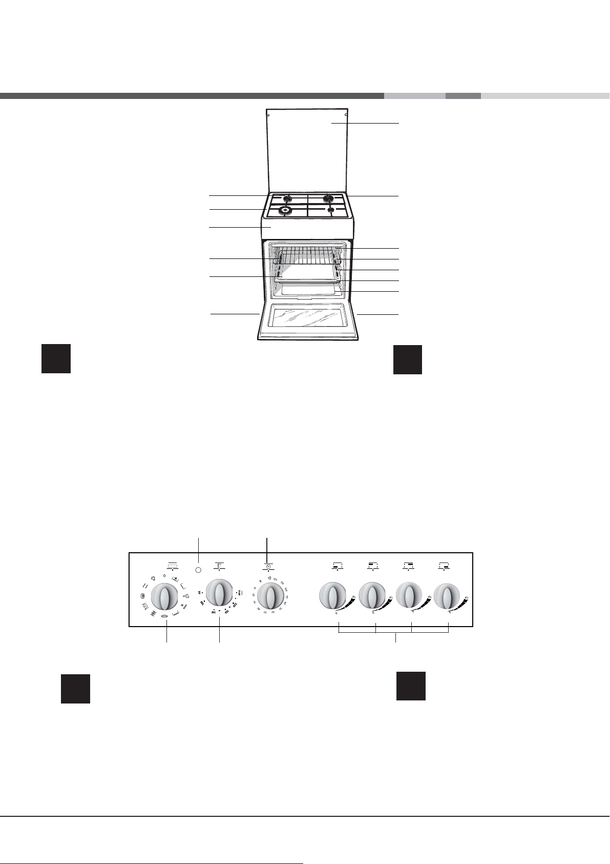
Description of the appliance
Overall view
1. Hob burner
2.Hob Grid
3.Control panel
4.Sliding grill rack
5.DRIPPING pan
6.Adjustable foot
7.Containment surface for spills
8.GUIDE RAILS for the sliding racks
9.position 5
10.position 4
11.position 3
12.position 2
13.position 1
14.Glass Cover
רישכמה רואית
HE
תיללכ הריקס
רונתה ירעבמ .1
םייריכה דירג .2
הרקב חול .3
קילחמ לירג שגמ .4
ףוטפט שגמ .5
תננווכתמ לגר .6
תופילדל חטשמ .7
םיקילחמה םישגמל תוליסמ .8
5 החונת.9
4 החונת.10
3 החונת.11
2 החונת.12
1 החונת.13
2
4
תיכוכז הסכמ.14
15
GB
Description of the appliance
Control panel
1.SELECTOR knob
2.THERMOSTAT indicator light
3.THERMOSTAT knob
4.TIMER knob*
5.Hob BURNER control knob
3
רישכמה רואית
HE
טטסומרט ןווחמ רוא .2
םייריכ רעבמ הרקב תידי .5
הרקב חול
הריחב תידי .1
טטסומרט תידי .3
*ןמז בצוק תידי .4
3
Installation
GB
! Before operating your new appliance please read
this instruction booklet carefully. It contains important
information concerning the safe installation and operation
of the appliance.
! Please keep these operating instructions for future
reference. Make sure that the instructions are kept with
the appliance if it is sold, given away or moved.
! The appliance must be installed by a qualified
professional according to the instructions provided.
! Any necessary adjustment or maintenance must be
performed after the cooker has been disconnected from
the electricity supply.
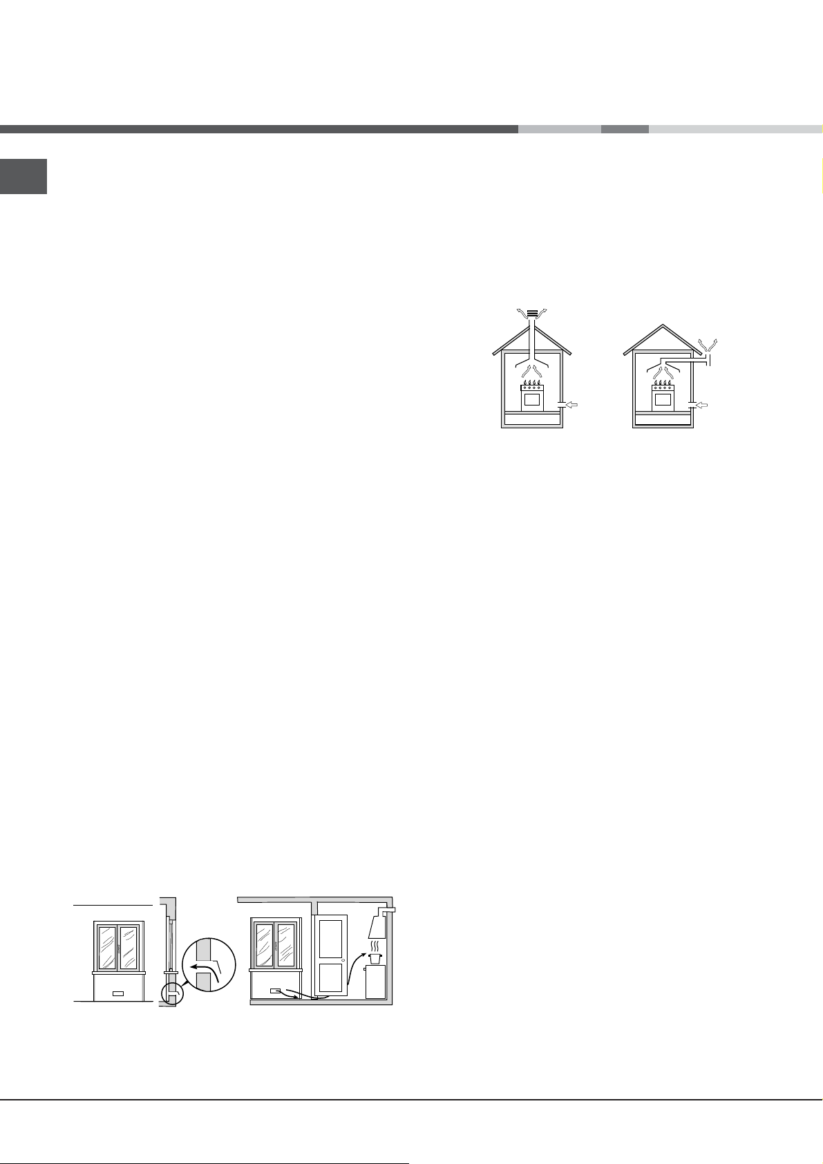
Room ventilation
The appliance may only be installed in permanentlyventilated rooms, in accordance with current national
legislation. The room in which the appliance is installed
must be ventilated adequately so as to provide as much
air as is needed by the normal gas combustion process
(the flow of air must not be lower than 2 m
installed power).
The air inlets, protected by grilles, should have a duct
with an inner cross section of at least 100 cm
be positioned so that they are not liable to even partial
obstruction (see gure A).
These inlets should be enlarged by 100% - with a
minimum of 200 cm
is not equipped with a flame failure safety device. When
the flow of air is provided in an indirect manner from
adjacent rooms (see gure B), provided that these are
not communal parts of a building, areas with increased
fire hazards or bedrooms, the inlets should be fitted with
a ventilation duct leading outside as described above.
Adjacent room Room requiring ventilation
A B
Ventilation opening Increase in the gap
between
for comburent air the door and the
flooring
! After prolonged use of the appliance, it is advisable to
open a window or increase the speed of any fans used.
2
- whenever the surface of the hob
A
3
/h per kW of
2
and should
Disposing of combustion fumes
The disposal of combustion fumes should be guaranteed
using a hood connected to a safe and efficient natural
suction chimney, or using an electric fan that begins
to operate automatically every time the appliance is
switched on (see gure).
Fumes channelled Fumes channelled through
straight outside a chimney or a branched
flue system (reserved for
cooking appliances)
! The liquefied petroleum gases are heavier than air and
collect by the floor, therefore all rooms containing LPG
cylinders must have openings leading outside so that
any leaked gas can escape easily.
LPG cylinders, therefore, whether partially or completely
full, must not be installed or stored in rooms or storage
areas that are below ground level (cellars, etc.). Only
the cylinder being used should be stored in the room;
this should also be kept well away from sources of
heat (ovens, chimneys, stoves) that may cause the
temperature of the cylinder to rise above 50°C.
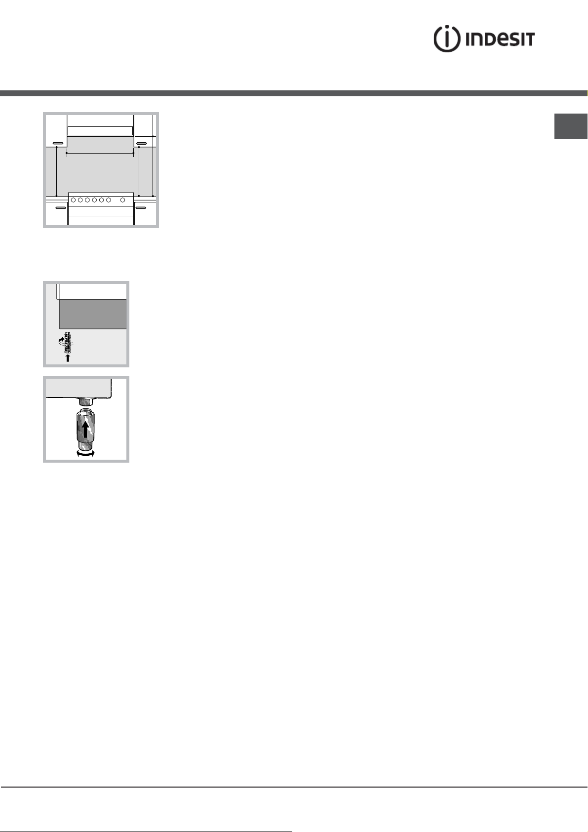
Positioning and levelling
! It is possible to install the appliance alongside
cupboards whose height does not exceed that of the
hob surface.
! Make sure that the wall in contact with the back of the
appliance is made from a non-flammable, heat-resistant
material (T 90°C).
To install the appliance correctly:
• Place it in the kitchen, the dining room or the bed-sit
(not in the bathroom).
• If the top of the hob is higher than the cupboards, the
appliance must be installed at least 600 mm away from
them.
• If the cooker is installed underneath a wall cabinet,
there must be a minimum distance of 420 mm between
this cabinet and the top of the hob.
This distance should be increased to 700 mm if the wall
cabinets are flammable (see gure).
4
Levelling
HOOD
420
Min.
min.
650
mm. with hood
min.
700
mm. without hood
mm.
600
Min. mm.
420
Min. mm.
• Do not position blinds
behind the cooker or less
than 200 mm away from
its sides.
• Any hoods must be
installed according to
the instructions listed in
the relevant operating
manual.
If it is necessary to level the
appliance, screw the adjustable
feet into the places provided on
each corner of the base of the
cooker (see gure).
The legs* fit into the slots on the
underside of the base of the
cooker.
! Once the appliance has been installed, the power
supply cable and the electrical socket must be easily
accessible.
! The cable must not be bent or compressed.
! The cable must be checked regularly and replaced by
authorised technicians only.
! The manufacturer declines any liability should these
safety measures not be observed.
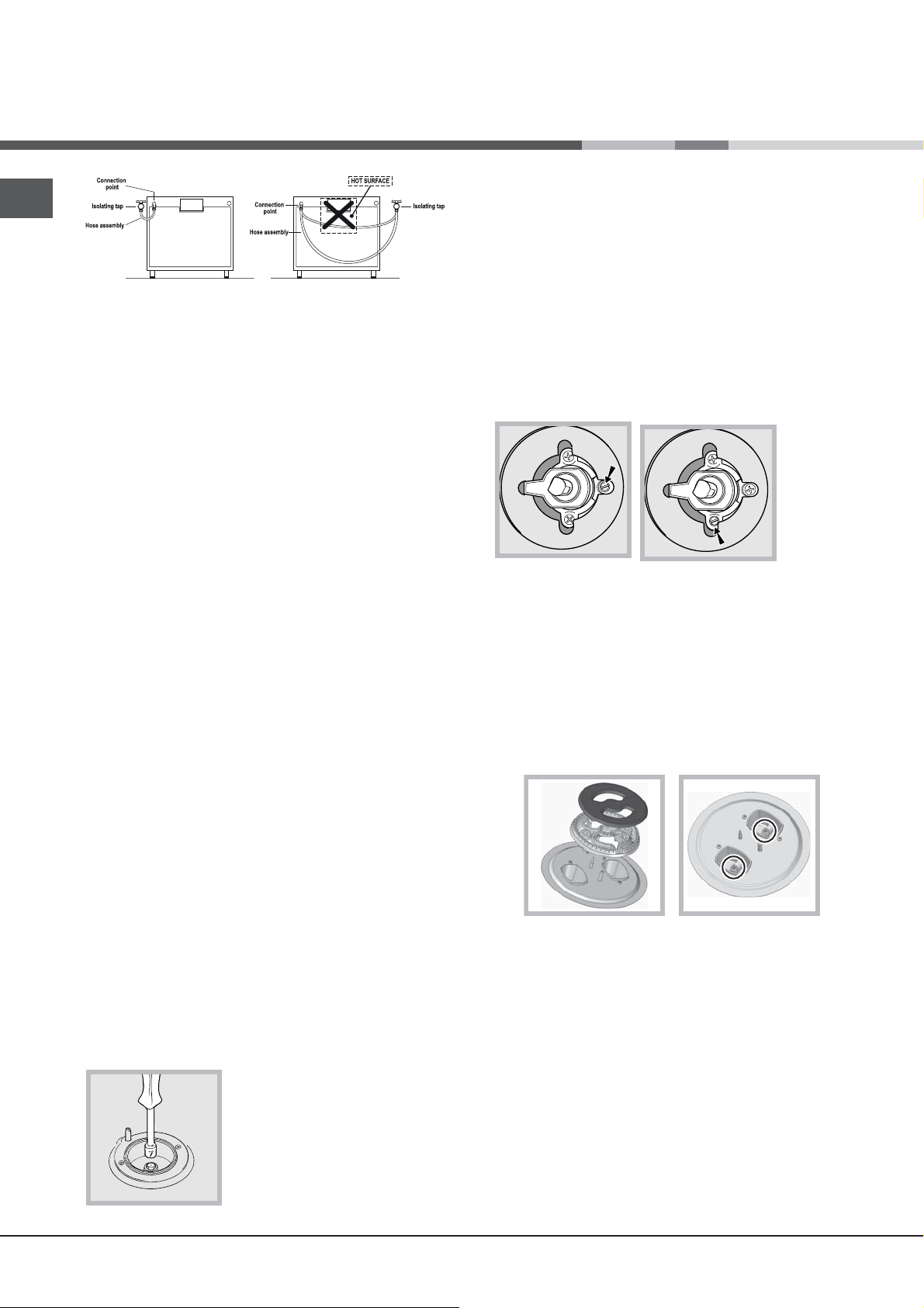
Gas connection
Connection to the gas network or to the gas cylinder
may be carried out using a flexible rubber or steel hose,
in accordance with current national legislation and after
making sure that the appliance is suited to the type of gas
with which it will be supplied (see the rating sticker on
the cover: if this is not the case see below). When using
liquid gas from a cylinder, install a pressure regulator
which complies with current national regulations. To
make connection easier, the gas supply may be turned
sideways*: reverse the position of the hose holder with
that of the cap and replace the gasket that is supplied
with the appliance.
GB
Electrical connection
Install a standardised plug corresponding to the load
indicated on the appliance data plate (see Technical data
table).
The appliance must be directly connected to the mains using
an omnipolar circuit-breaker with a minimum contact opening
of 3 mm installed between the appliance and the mains. The
circuit-breaker must be suitable for the charge indicated and
must comply with current electrical regulations (the earthing
wire must not be interrupted by the circuit-breaker). The
supply cable must be positioned so that it does not come
into contact with temperatures higher than 50°C at any point.
Before connecting the appliance to the power supply,
make sure that:
• The appliance is earthed and the plug is compliant with
the law.
• The socket can withstand the maximum power of the
appliance, which is indicated by the data plate.
• The voltage is in the range between the values
indicated on the data plate.
• The socket is compatible with the plug of the appliance.
If the socket is incompatible with the plug, ask
an authorised technician to replace it. Do not use
extension cords or multiple sockets.
! Check that the pressure of the gas supply is consistent
with the values indicated in the Table of burner and
nozzle specifications (see below). This will ensure the
safe operation and durability of your appliance while
maintaining efficient energy consumption.
Gas connection using a flexible rubber hose
Make sure that the hose complies with current national
legislation. The internal diameter of the hose must
measure: 8 mm for liquid gas supply; 13 mm for methane
gas supply.
Once the connection has been performed, make sure
that the hose:
• Does not come into contact with any parts that reach
temperatures of over 50°C.
• Is not subject to any pulling or twisting forces and that
it is not kinked or bent.
• Does not come into contact with blades, sharp corners
or moving parts and that it is not compressed.
• Is easy to inspect along its whole length so that its
condition may be checked.
• Is shorter than 1500 mm.
• Fits firmly into place at both ends, where it will be fixed
using clamps that comply with current regulations.
*Available only on certain models
5
GB
! If one or more of these conditions is not fulfilled or if
the cooker must be installed according to the conditions
listed for class 2 - subclass 1 appliances (installed
between two cupboards), the flexible steel hose must
be used instead (see below).
Connecting a flexible jointless stainless steel pipe to
a threaded attachment
Make sure that the hose and gaskets comply with current
national legislation.
To begin using the hose, remove the hose holder on the
appliance (the gas supply inlet on the appliance is a
cylindrical threaded 1/2 gas male attachment).
quickly change the position of the knob from minimum
to maximum and vice versa several times, checking that
the flame is not extinguished.
! The hob burners do not require primary air adjustment.
! After adjusting the appliance so it may be used with a
different type of gas, replace the old rating label with a
new one that corresponds to the new type of gas (these
labels are available from Authorised Technical Assistance
Centres).
! Should the gas pressure used be different (or vary
slightly) from the recommended pressure, a suitable
pressure regulator must be fitted to the inlet hose in
accordance with current national regulations relating
! Perform the connection in such a way that the hose
length does not exceed a maximum of 2 metres, making
sure that the hose is not compressed and does not come
into contact with moving parts.
Checking the tightness of the connection
When the installation process is complete, check the hose
fittings for leaks using a soapy solution. Never use a flame.
Adapting to different types of gas
It is possible to adapt the appliance to a type of gas other
than the default type (this is indicated on the rating label
on the cover).
Adapting the hob
Replacing the nozzles for the hob burners:
1. Remove the hob grids and slide the burners off their
seats.
2. Unscrew the nozzles using a 7 mm socket spanner
(see gure), and replace them with nozzles suited to the
new type of gas (see Burner and nozzle speci cations table).
3. Replace all the components by following the above
instructions in reverse.
Adjusting the hob burners’ minimum setting:
1. Turn the tap to the minimum position.
2. Remove the knob and adjust the regulatory screw,
which is positioned inside or next
to the tap pin, until the flame is
small but steady.
! If the appliance is connected to
a liquid gas supply, the regulatory
screw must be fastened as tightly
as possible:
3. While the burner is alight,
Replacing the Triple ring burner nozzles
1. Remove the pan supports and lift the burners out of
their housing. The burner consists of two separate
parts (see pictures).
2. Unscrew the nozzles using a 7 mm socket spanner.
Replace the nozzles with models that are configured
for use with the new type of gas (see Table 1). The two
nozzles have the same hole diameter.
3. Replace all the components by completing the above
operations in reverse order.
• Adjusting the burners’ primary air :
Does not require adjusting.
• Setting the burners to minimum:
1. Turn the tap to the low flame position.
2. Remove the knob and adjust the adjustment screw,
which is positioned in or next to the tap pin, until the
flame is small but steady.
3. Having adjusted the flame to the required low setting,
while the burner is alight, quickly change the position
of the knob from minimum to maximum and vice versa
several times, checking that the flame does not go out
4. Some appliances have a safety device (thermocouple)
fitted. If the device fails to work when the burners are
set to the low flame setting, increase this low flame
setting using the adjusting screw.
6
S
R
TC A
5. Once the adjustment has been made, replace the seals
on the by-passes using sealing wax
! If the appliance is connected to liquid gas, the regulation
screw must be fastened as tightly as possible.
! Once this procedure is finished, replace the old rating
sticker with one indicating the new type of gas used.
Stickers are available from any of our Service Centres.
! Should the gas pressure used be different (or vary
slightly) from the recommended pressure, a suitable
pressure regulator must be fitted to the inlet pipe (in order
to comply with current national regulations).
I6TMH2AF /IL
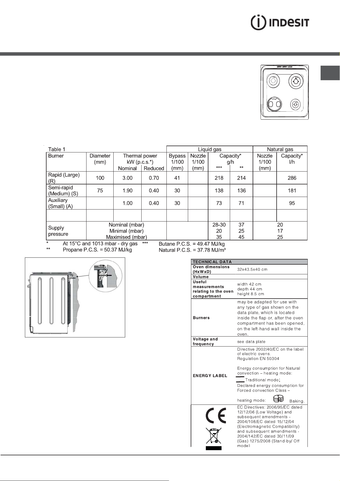
Table of burner and nozzle specifications
GB
51
3.25 1.50 2x65
Tripple Ring (TC)
130
Safety Chain
! In order to prevent accidental tipping of the appliance,
for example by a child climbing onto the oven door, the
supplied safety chain MUST be installed!
The cooker is fitted with a safety chain to be fixed by
means of a screw (not supplied with the cooker) to the
wall behind the appliance, at the same height as the chain
is attached to the appliance.
Choose the screw and the screw anchor according to
the type of material of the wall behind the appliance. If
the head of the screw has a diameter smaller than 9mm,
a washer should be used. Concrete wall requires the
screw of at least 8mm of diameter, and 60mm of length.
Ensure that the chain is fixed to the rear wall of the cooker
and to the wall, as shown in figure, so that after installation
it is tensioned and parallel to the ground level.
63
87
69
50
128
104
78
236 232 2x99 309
59 l
7
Start-up and use
GB
Using the hob
Lighting the burners
For each BURNER knob there is a complete ring showing
the strength of the flame for the relevant burner.
To light one of the burners on the hob:
1. Bring a flame or gas lighter close to the burner.
2. Press the BURNER knob and turn it in an anticlockwise
direction so that it is pointing to the maximum flame
setting .
3. Adjust the intensity of the flame to the desired level by
turning the BURNER knob in an anticlockwise direction. This
may be the minimum setting , the maximum setting or
any position in between the two.
If the appliance is fitted with an
electronic lighting device* (see
gure), press the ignition button,
marked with the symbol
hold the BURNER knob down
and turn it in an anticlockwise
direction, towards the maximum
flame setting, until the burner
is lit.The burner may be extinguished when the knob is
released. If this occurs, repeat the operation, holding the
knob down for a longer period of time.
! If the flame is accidentally extinguished, switch off the
burner and wait for at least 1 minute before attempting
to relight it.
If the appliance is equipped with a flame failure
safety device*, press and hold the BURNER knob for
approximately 2-3 seconds to keep the flame alight and
to activate the device.
To switch the burner off, turn the knob until it reaches
the stop position •.
Flame adjustment according to levels
the burner flame intensity can be adjusted with the knob
according to 6 power levels, from maximum to minimum
with 4 intermediate positions:
a click will indicate the change from one level to another
when turning the knob. The system guarantees a more
precise adjustment, allows to replicate the flame intensity
and to identify easily the preferred level for different
cooking operations.
WARNING! The glass lid can break
in if it is heated up. Turn off all the
burners and the electric plates before closing the lid.
, then
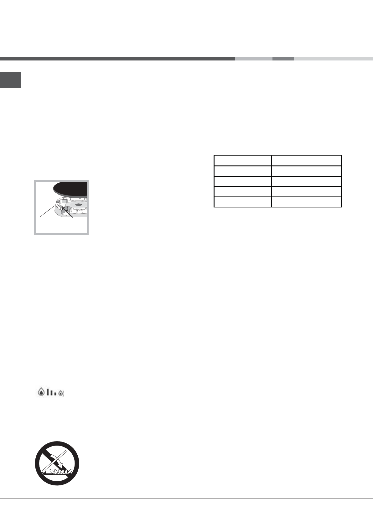
Practical advice on using the burners
For the burners to work in the most efficient
way possible and to save on the amount of gas
consumed, it is recommended that only pans that have
a lid and a flat base are used. They should also be suited
to the size of the burner:
To identify the type of burner, please refer to the diagrams
contained in the “Burner and nozzle specifications”.
Burner Cookware Diameter (cm)
Fast (R) 24 - 26
Semi Fast (S) 16 - 20
Auxiliary (A) 10 - 14
Triple Crown (TC) 24 - 26
! For models equipped with a reducer grid, the latter must
be used only for the auxiliary burner, when pans with a
diameter of less than 12 cm are used.
Using the oven
! The first time you use your appliance, heat the empty
oven with its door closed at its maximum temperature
for at least half an hour. Ensure that the room is well
ventilated before switching the oven off and opening the
oven door. The appliance may emit a slightly unpleasant
odour caused by protective substances used during the
manufacturing process burning away.
! Before operating the product, remove all plastic film
from the sides of the appliance.
! Never put objects directly on the bottom of the oven; this
will avoid the enamel coating being damaged.
1. Select the desired cooking mode by turning the
SELECTOR knob.
2. Select the recommended temperature for the
cooking mode or the desired temperature by turning the
THERMOSTAT knob.
A list detailing cooking modes and suggested cooking
temperatures can be found in the relevant table (see Oven
cooking advice table).
During cooking it is always possible to:
• Change the cooking mode by turning the SELECTOR
knob.
• Change the temperature by turning the THERMOSTAT
knob.
• Stop cooking by turning the SELECTOR knob to the
“0” position.
*
Only available in certain models.
8
! Always place cookware on the rack(s) provided.
THERMOSTAT indicator light
When this is illuminated, the oven is generating heat.
It switches off when the inside of the oven reaches the
selected temperature. At this point the light illuminates
and switches off alternately, indicating that the thermostat
is working and is maintaining the temperature at a
constant level.
Oven light
This is switched on by turning the SELECTOR knob to
any position other than “0”. It remains lit as long as the
oven is operating. By selecting
light is switched on without any of the heating elements
being activated.
with the knob, the
Cooking modes
! A temperature value can be set for all cooking modes
between 60°C and Max, except for the following modes
• GRILL (recommended: set only to MAX power level)
• GRATIN (recommended: do not exceed 200°C).
constant throughout the oven, the air cooks and browns
food in a uniform manner. A maximum of two racks may
be used at the same time.
PIZZA mode
The circular heating elements and the elements at
the bottom of the oven are switched on and the fan is
activated. This combination heats the oven rapidly by
producing a considerable amount of heat, particularly
from the element at the bottom. If you use more than one
rack at a time, switch the position of the dishes halfway
through the cooking process.
GRILL mode
The central part of the top heating element is switched
on. The high and direct temperature of the grill is
recommended for food that requires a high surface
temperature (veal and beef steaks, fillet steak and
entrecôte). This cooking mode uses a limited amount of
energy and is ideal for grilling small dishes. Place the food
in the centre of the rack, as it will not be cooked properly
if it is placed in the corners.
GB
TRADITIONAL OVEN mode
Both the top and bottom heating elements will come on.
When using this traditional cooking mode, it is best to use
one cooking rack only. If more than one rack is used, the
heat will be distributed in an uneven manner.
BAKING mode
The rear heating element and the fan are switched on,
thus guaranteeing the distribution of heat in a delicate and
uniform manner throughout the entire oven. This mode is
ideal for baking and cooking temperature sensitive foods
(such as cakes that need to rise) and for the preparation
of pastries on 3 shelves simultaneously.
FAST COOKING mode
The heating elements and the fan come on, guaranteeing
the distribution of heat consistently and uniformly
throughout the oven.
Preheating is not necessary for this cooking mode. This
mode is particularly suitable for cooking pre-packed
food quickly (frozen or pre-cooked). The best results are
achieved using one cooking rack only.
MULTI-COOKING mode
GRATIN
The top heating element and the rotisserie (where
present) are activated and the fan begins to operate.
This combination of features increases the effectiveness
of the unidirectional thermal radiation provided by the
heating elements through forced circulation of the air
throughout the oven. This helps prevent food from burning
on the surface and allows the heat to penetrate right into
the food.
! The GRILL and GRATIN cooking modes must be
performed with the oven door shut.
DEFROSTING mode
The fan located on the bottom of the oven makes the air
circulate at room temperature around the food. This is
recommended for the defrosting of all types of food, but in
particular for delicate types of food which do not require
heat, such as for example: ice cream cakes, cream or
custard desserts, fruit cakes. By using the fan, the
defrosting time is approximately halved. In the case of
meat, fish and bread, it is possible to accelerate the
process using the “multi-cooking” mode and setting the
temperature to 80° - 100°C.
mode
All the heating elements (top, bottom and circular) switch
on and the fan begins to operate. Since the heat remains
9

GB
BOTTOM VENTILATED mode
The bottom heating element and the fan is activated,
which allows for the heat distribution within the whole
cavity of the oven. This combination is useful for light
cooking of vegetables and fish.
BOTTOM mode :
The lower heating element is activated. This position
is recommended for perfecting the cooking of dishes
(in baking trays) which are already cooked on the
surface but require further cooking in the centre, or
for desserts with a covering of fruit or jam, which only
require moderate colouring on the surface. It should
be noted that this function does not allow the maximum
temperature to be reached inside the oven (250°C)
and it is therefore not recommended that foods are
cooked using only this setting, unless you are baking
cakes (which should be baked at a temperature of
180°C or lower).
Practical cooking advice
Cooking Control Timer Knob
Some models are equipped with a timer program to
control when the oven shuts off during cooking. To use
this feature, you must wind the knob one full turn in the
counter-clockwise direction
; Then, turn the knob in
the clockwise direction , to set the time by matching
up the indicator on the control panel with the number
of minutes on the knob.
At the end of the programmed length of time, the timer
will sound and automatically turn off the oven.
Attention: to use the oven in manual mode without the
cooking control timer, match the indicator on the
control panel with the
symbol on the timer knob.
When the oven is not in use, the cooking control timer
can be used like a normal timer.
! In the GRILL cooking mode, place the dripping pan in
position 1 to collect cooking residues (fat and/or grease).
GRILL
• Insert the rack in position 3 or 4. Place the food in the
centre of the rack.
• We recommend that the power level is set to maximum.
The top heating element is regulated by a thermostat
and may not always operate constantly.
PIZZA
• Use a light aluminium pizza pan. Place it on the rack
provided.
For a crispy crust, do not use the dripping pan as it
prevents the crust from forming by extending the total
cooking time.
• If the pizza has a lot of toppings, we recommend
adding the mozzarella cheese on top of the pizza
halfway through the cooking process.
WARNING! The oven is provided with
a stop system to extract the racks and
prevent them from coming out of the
oven.(1)
As shown in the drawing, to extract
them completely , simply lift the racks,
holding them on the front part, and
pull (2).
10

Oven cooking advice table
GB
Cooking
modes
Traditional
Oven
Baking
Mode
Fast
cooking
Multi-
cooking
Pizza Mode
Grill
Gratin
Foods Weight
(in kg)
Rack Position Pre-heating
time
(minutes)
Duck
Roast veal or beef
Pork roast
Biscuits (short pastry)
Tarts
Tarts
Fruit cakes
Plum c ake
Sponge cake
Stuffed pancakes (on 2 racks)
Small cakes (on 2 racks)
Cheese puffs (on 2 racks)
Cream puffs (on 3 racks)
Biscuits (on 3 racks)
Meringues (on 3 racks)
Frozen food
Pizza
Courgette and prawn pie
Country style spinach pie
Turnovers
Lasagne
Golden Rolls
Chicken morsels
Pre-cooked food
Golden chicken wings
Fresh Food
Biscuits (short pastry)
Plum c ake
Cheese puffs
Pizza (on 2 racks)
Lasagne
Lamb
Roast chicken + potatoes
Mackerel
Plum c ake
Cream puffs (on 2 racks)
Biscuits (on 2 racks)
Sponge cake (on 1 rack)
Sponge cake (on 2 racks)
Savoury pies
Pizza
Roast veal or beef
Chicken
Soles and cuttlefish
Squid and prawn kebabs
Cuttlefish
Cod filet
Grilled vegetables
Veal steak
Sausages
Hamburgers
Mackerels
Toasted sandwiches (or toast)
Grilled chicken
Cuttlefish
1
1
1
-
1
0.5
1
0.7
0.5
1.2
0.6
0.4
0.7
0.7
0.5
0.3
0.4
0.5
0.3
0.5
0.4
0.4
0.4
0.3
0.6
0.2
1
1
1
1+1
1
1
0.5
0.5
0.5
1
1.5
0.5
1
1
0.7
0.6
0.6
0.8
0.4
0.8
0.6
0.6
1
4 and 6
1.5
1.5
3
3
3
3
3
3
2 or 3
3
3
2 and 4
2 and 4
2 and 4
1 and 3 and 5
1 and 3 and 5
1 and 3 and 5
2
2
2
2
2
2
2
2
2
2
2
2 and 4
3
2
2 and 4
2
2
2 and 4
2 and 4
2
2 and 4
3
3
2
2 or 3
4
4
4
4
3 or 4
4
4
4
4
4
2
2
15
15
15
15
15
15
15
15
15
15
15
15
15
15
15
15
10
10
15
10
10
10
10
10
10
15
15
10
10
10
10
-
-
-
-
-
-
-
-
-
-
-
-
-
-
-
-
-
-
-
-
-
Recommended
temperature
200
200
200
180
180
180
180
180
160
200
190
210
180
180
90
250
200
220
200
200
180
220
200
200
180
210
230
180
180
200
180
170
190
180
170
170
200
220
220
180
Max
Max
Max
Max
Max
Max
Max
Max
Max
Max
200
200
Cooking
time
(minutes)
65-75
70-75
70-80
15-20
30-35
20-30
40-45
40-50
25-30
30-35
20-25
15-20
20-25
20-25
180
12
20
30-35
25
35
25-30
15-20
20-25
15-18
45
10-12
15-20
30-35
40-45
60-70
30-35
40-50
20-25
10-15
15-20
20-25
25-30
15-20
25-30
60-70
10-12
8-10
10-15
10-15
15-20
15-20
15-20
10-12
15-20
3-5
55-60
30-35
Bottom
Ventilated
Bottom
For perfecting cooking
11

Precautions and tips
GB
! This appliance has been designed and manufactured
in compliance with international safety standards.
The following warnings are provided for safety reasons
and must be read carefully.
General safety
• The appliance was designed for domestic use inside
the home and is not intended for commercial or
industrial use.
• The appliance must not be installed outdoors, even in
covered areas. It is extremely dangerous to leave the
appliance exposed to rain and storms.
• Do not touch the appliance with bare feet or with wet
or damp hands and feet.
• The appliance must be used by adults only for
the preparation of food, in accordance with the
instructions outlined in this booklet. Any other
use of the appliance (e.g. for heating the room)
constitutes improper use and is dangerous.
The manufacturer may not be held liable for any
damage resulting from improper, incorrect and
unreasonable use of the appliance.
• The instruction booklet accompanies a class 1
(insulated) or class 2 - subclass 1 (recessed between
2 cupboards) appliance.
• Do not touch the heating elements or certain parts
of the oven door when the appliance is in use;
these parts become extremely hot. Keep children
well away from the appliance.
• Make sure that the power supply cables of other
electrical appliances do not come into contact with
the hot parts of the oven.
• The openings used for the ventilation and dispersion
of heat must never be covered.
• Always use oven gloves when placing cookware in the
oven or when removing it.
• Do not use flammable liquids (alcohol, petrol, etc...)
near the appliance while it is in use.
• Do not place flammable material in the lower storage
compartment or in the oven itself. if the appliance is
switched on accidentally, they could catch fire.
• The internal surfaces of the compartment (where
present) may become hot.
•
• Always make sure the knobs are in the
the appliance is not in use.
• When unplugging the appliance, always pull the plug
from the mains socket; do not pull on the cable.
• Never perform any cleaning or maintenance work
without having disconnected the appliance from the
electricity mains.
• If the appliance breaks down, under no circumstances
should you attempt to perform the repairs yourself.
Repairs carried out by inexperienced persons may
cause injury or further malfunctioning of the appliance.
Contact Assistance.
position when
• Do not rest heavy objects on the open oven door.
• The appliance should not be operated by people
(including children) with reduced physical, sensory
or mental capacities, by inexperienced individuals or
by anyone who is not familiar with the product. These
individuals should, at the very least, be supervised
by someone who assumes responsibility for their
safety or receive preliminary instructions relating to
the operation of the appliance.
• Do not let children play with the appliance.
•If the cooker is placed on a pedestal, take the necessary
precautions to prevent the cooker from sliding off the
pedestal itself.
Disposal
• When disposing of packaging material: observe local
legislation so that the packaging may be reused.
• The European Directive 2002/96/EC relating to Waste
Electrical and Electronic Equipment (WEEE) states
that household appliances should not be disposed of
using the normal solid urban waste cycle. Exhausted
appliances should be collected separately in order to
optimise the cost of re-using and recycling the materials
inside the machine, while preventing potential damage
to the atmosphere and to public health. The crossedout dustbin is marked on all products to remind the
owner of their obligations regarding separated waste
collection.
For further information relating to the correct disposal of
exhausted household appliances, owners may contact
the public service provided or their local dealer.
Respecting and conserving the
environment
• You can help to reduce the peak load of the electricity
supply network companies by using the oven in the
hours between late afternoon and the early hours of
the morning.
• Always keep the oven door closed when using the
GRILL and DOUBLE GRILL modes. This will achieve
better results while saving energy (approximately
10%).
• Check the door seals regularly and wipe them clean
to ensure they are free of debris so that they adhere
properly to the door, thus avoiding heat dispersion.
12

Care and maintenance
Switching the appliance off
Disconnect your appliance from the electricity supply
before carrying out any work on it.
Cleaning the appliance
! Never use steam cleaners or pressure cleaners on the
appliance.
• The stainless steel or enamel-coated external parts and
the rubber seals may be cleaned using a sponge that
has been soaked in lukewarm water and neutral soap.
Use specialised products for the removal of stubborn
stains. After cleaning, rinse well and dry thoroughly.
Do not use abrasive powders or corrosive substances.
• The hob grids, burner caps, flame spreader rings and
burners may be removed to make cleaning easier;
wash them in hot water and non-abrasive detergent,
making sure all burnt-on residue is removed before
drying them thoroughly.
Replacing the oven light bulb
1. After disconnecting the oven
from the electricity mains, remove
the glass lid covering the lamp
socket (see gure).
2. Remove the light bulb and
replace it with a similar one:
voltage 230 V, wattage 25 W,
cap E 14.
3. Replace the lid and reconnect
the oven to the electricity supply.
! Do not use the oven lamp as/for ambient lighting.
Gas tap maintenance
Over time, the taps may become jammed or difficult to
turn. If this occurs, the tap must be replaced.
! This procedure must be performed by a qualified
technician authorised by the manufacturer.
Assistance
GB
• Clean the terminal part of the flame failure safety
devices* frequently.
• The inside of the oven should ideally be cleaned after
each use, while it is still lukewarm. Use hot water and
detergent, then rinse well and dry with a soft cloth. Do
not use abrasive products.
• Clean the glass part of the oven door using a sponge
and a non-abrasive cleaning product, then dry
thoroughly with a soft cloth. Do not use rough abrasive
material or sharp metal scrapers as these could
scratch the surface and cause the glass to crack.
• The accessories can be washed like everyday
crockery, and are even dishwasher safe.
• Do not close the cover when the burners are alight or
when they are still hot.
Inspecting the oven seals
Check the door seals around the oven regularly. If
the seals are damaged, please contact your nearest
Authorised After-sales Service Centre. We recommend
that the oven is not used until the seals have been
replaced.
! Never use the services of an unauthorised technician.
Please have the following information to hand:
• The type of problem encountered.
• The appliance model (Mod.).
• The serial number (S/N).
The latter two pieces of information can be found on the
data plate located on the appliance.
Removing and fitting the oven door:
1.Open the door
2.Make the hinge clamps of the oven door rotate
backwards completely (see photo)
3.Close the door until the clamps stop (the door will
remain open for 40° approx.) (see photo)
13

GB
40°
4.Press the two buttons on the upper profile and
extract the profile (see photo)
10.Now the door can be completely closed and the
oven can be started for normal use.
5.Remove the glass sheet and do the cleaning as
indicated in chapter: "Care and maintenance".
6.Replace the glass.
WARNING! Oven must not be operated with inner
door glass removed!
WARNING! When reassembling the inner door
glass insert the glass panel correctly so that the
text written on the panel is not reversed and
can be easily legible.
7.Replace the profile, a click will indicate that the
part is positioned correctly.
8.Open the door completely.
9.Close the supports (see photo).
14

Steam-Assisted Oven Cleaning
This method of cleaning is recommended especially after
cooking very fatty (roasted)meats.
This cleaning process allows to facilitate the removal of
dirt of the walls of the oven by the generation of steam
that is created inside the oven cavity for easier cleaning.
! Important! Before you start steam -cleaning:
-Remove any food residue and grease from the bottom
of the oven.
- Remove any oven accessories (grids and drip pans).
Perform the above operations according to the following
procedure:
1. pour 300ml of water into the baking tray in the oven,
placing it in the bottom shelf. In the models where the
drip pan is not present, use a baking sheet and place it
on the grill at the bottom shelf;
2. select the function of the oven: BOTTOM
set the temperature to 100 ° C;
3. keep it in the oven for 15min;
4. turn off the oven;
5. Once cooled the oven, you can open the door to
complete the cleaning with water and a damp cloth;
6. eliminate any residual water from the cavity after
finishing cleaning
and
GB
When the steam –cleaning is done, after cooking
especially fatty foods, or when grease is difficult to
remove, you may need to complete the cleaning with the
traditional method, described in the previous paragraph.
! Perform cleaning only in the cold oven!
15

הנקתה
HE
הריעב ידא קוליס
רבוחמה ימיכ ףדנמב שומיש ידי לע הריעב ידא קוליס חיטבהל שי
ררוואמב שומיש ידי לע וא ,החוטב תיעבט הביאש תבוראל
האר( קלדנ רישכמהש םעפ לכב תיטמוטוא לעפומה ינורטקלא
.)רויא
הצוחה תורישי םילעותמ םידא
,הפצרל ךומס ףסאנו ריוואמ רתוי דבכ הבועמ ינומימחפ זג !
םיליבומה םיחתפ תויהל םיבייח מ”פג שי םהב םירדחה לכב ןכל
.תולקב קלסיהל לכוי ףלוד זג לכש ךכ הצוחה
תחתמ םיללחב מ”פגה ילילג תא ןסחאל וא ןיקתהל רוסא ,ןכ לע
תויהל םיכירצ שומישבש םילילגה קר )המודכו םיפתרמ( עקרקל
םוח תורוקממ םתקחרהל בטיה גואדל שי ;רדחב םינסחואמ
לילגה תרוטרפמטל םורגל םייושעש )םייריכ ,תובורא ,םירונת(
וא הבורא ךרד םילעותמ םידא
ירישכמל תדחוימ( קלד תכרעמ
)לושיב
.50°C-ל לעמ תולועל
.הז תוארוה רפס ןויעב ארק אנא שדחה ךרישכמ תלעפה ינפל !
.רישכמה לש החוטב הלעפהו הנקתה יבגל בושח עדימ ליכמ אוה
םג ןהב ןייעל לכותש ידכ ולא תוארוה די גשיהב רומש אנא !
התאו הדימב רישכמה םע דחי תואצמנ תוארוהה יכ אדו .דיתעב
.הריד ותוא ריבעמ וא ,הנתמב ותוא רסומ ,ותוא רכומ
םאתהב רשכומ עוצקמ לעב ידי לע ןקתומ תויהל בייח רישכמה !
.תוקפוסמה תוארוהל
גוס לכ וב עצבמ התאש ינפל למשחהמ רישכמה תא קתנל שי !
.לופיט לש
רדחה רורוויא
,דימת םיררוואמה םירדחב קרו ךא רישכמה תא ןיקתהל שי
ןקתומ רישכמה וב רדחה .תיחכונה תימואלה הקיקחל םאתהב
ריווא תומכ קפסי אוהש ךכ ,היואר הרוצב ררוואמ תויהל בייח
ריוואה םרז לע( ליגר זג תריעב ךילהת ךרוצל הצוחנה תקפסמ
)ןקתומ חכ לש kW לכל העש/m3 2 לעמ תויהל
םע רוניצ היהי םיגרוס ידי לע םינגומה ריוואה יחתפלש גואדל שי
ךכ םיבצומ תויהל םהילעו תוחפל 2מ”ס 100 לדוגב ימינפ ךתח
האר( .תיקלח אל וליפא ,איהש המיתס םושל םיפושח ויהי אלש
.)’א רויא
הדימב -ר”מס 200 םומינימ -אלמה םלדוגל ולא םיחתפ לידגהל שי
ריווא םרז קפוסמ רשאכ .ןוחטיב ןקתהב הוולמ אל םייריכה סיסבו
םיקלחב רבודמש הדימב ,)’ב רויא האר( ךומס רדחמ רישי אל
,הניש ירדח וא תרבגומ הפירש תנכסב םיללח ,ןיינבב םיירוביצ אל
הצוחה ליבומה רורוויא רוניצב םירזבואמ תויהל םיבייח םיחתפה
.ליעל ראותמכ
סוליפו הבצה
לע הלוע וניא םלקשמש תונורא דיל רישכמה תא ביצהל ןתינ !
.ףדנמה סיסב לקשמ
םוחל ןיסח רמוחמ יושע רישכמה ירוחא םע עגמבש ריקה יכ אדו !
.)90°C ’פמט( קילד וניאש
:הנוכנה הרוצב רישכמה תא ןיקתהל תנמ לע
אל( רדחה תריד ךותב וא לכואה רדחב ,חבטמב ותוא םקמ
.)תחלקמב וא םיתורישב
שי ,ןוראהמ רתוי הובג םייריכה לש ןוילעה הצקהו הדימב
.םהמ מ”מ 600 תוחפל לש קחרמב רישכמה תא ןיקתהל
קחרמ תויהל ךירצ ,ריק ןוראל תחתמ ןקתומ רישכמהו הדימב
.םייריכה הצקל ןוראה ןיב מ”מ 420 לש ילמינימ
.)רויא האר( קילד רמוחמ יושע ריקה ןוראו הדימב מ”מ 700 וא
רורוויא שרודה רדח ךומס רדח
א
ריווא תפצר רובע רורוויא חתפ
הריעב
A
ריבגהל וא ןולח חותפל ץלמומ ,רישכמב ךשוממ שומיש רחאל !
.שומישב אצמנ אוהו הדימב ,ררוואמה תוריהמ תא
חוורמב הלדגה
תלדה ןיב
ב
16

תויהל םיבייח עקשהו למשחה לבכ ,רישכמה תא תנקתהש עגרב !
.השיגל םיחונ
.סוחד וא ףפוכמ היהי לבכהש רוסא !
יאשר השרומ יאנכט קר .לבכה תא רידס ןפואב קודבל שי !
.ותוא ףילחהל
רבדה ,הכלהכ תמשוימ אל ל”נה תוחיטבה תוארוהו הדימב !
.ןרציה תוירחאב וניא
ירוחאמ תונוליו חינהל ןיא
לש קחרמב וא רישכמה
.וידדצמ מ”מ 200-מ תוחפ
ףדנמה תא ןיקהל שי
תוטרופמה תוארוהה יפל
.יטנוולרה הלעפהה ךירדמב
HE
זג רוביח
ימוג רוניצ תועצמאב זג ילילגל וא זג תשרל רוביח עצבל ןתינ
רחאל ,תיחכונה תימואלה הקיקחל םאתהב ,הדלפ רוניצ וא שימג
הקבדמ האר( קפוסמה זגה גוסל םיאתמ רישכמה יכ תאדיו יכ
ךניהו הדימב .)הטמל האר בצמה אל הזו הדימב :הפיטעה לע
תא םאות רשא ץחל תסו ןקתה אנא ,לילגמ ילזונ זגב שמתשמ
בבוסל שי ,רוביחה לע לקהל תנמ לע .תיחכונה תימואלה הקיקחה
רוניצה קיזחמ לש םוקימה ןיב ךופה :*דצה לע זגה תקפסא תא
.רישכמה םע קפוסמ רשא םטאה תא ףלחהו הקיפה םוקימל
םינייוצמה םיכרעה תא םאות זגה תקפסא לש ץחלה יכ אדו !
חיטבי רבדה .)הטמל האר( ”תיבוברזו רעבמ יטרפמ“ הלבטב
תכירצ לע הרימש ןמזב ,ותודימע תאו רישכמה לש חוטב לועפת
.הליעי היגרנא
ימוג רוניצב שומיש תועצמאב זגל רוביח
ךרוא .תיחכונה תימואלה הקיקחה תא םאות רוניצה יכ אדו אנא
זג תקפסא רובע מ”מ 8 :תויהל ךירצ רוניצה לש ימינפה רטוקה
.ןאתמ זג תקפסא רובע מ”מ 13 ;ילזונ
:רוניצה יכ אדו אנא ,רוביחה תא תעציבש עגרב
.50°C לעמ הרוטרפמטל םיעיגמ רשא םיקלח םע עגמב אב אל
,ותוא בבוסמ וא ותוא ךשומ רשא חכ רוניצה לע לעפומ אל
.ףפוכמ וא לתופמ וניא אוהשו
אוהשו ,םיזז םיקלח וא תודח תוניפ ,םיבהל םע עגמב אב אל
.סוחד וניא
קודבל היהי ןתינש ךכ ,וכרוא לכ ךרואל שמתשמל שיגנ רוניצה
.ובצמ תא
.מ”מ 1500-מ רתוי ךומנ רוניצה
ינשב ותוא חטבאל שי ;ויתווצק ינשב תוחיטבב םוקמב בשוי
.תיחכונה הקיקחה תא םימאותה םייצחלמ תועצמאב ויתווצק
סוליפ
שי ,רישכמה תא סלפל ךרוצ שיו הדימ
לא תוננווכתמה םיילגרה תא גירבהל
ןמ תחא לכב םיקפוסמה םידמעמה
.)רויא האר( רונתה סיסב לש תוניפה
קלחב םיצירחל תומיאתמ םיילגרה
.רונתה סיסב לש ןותחתה
למשחל רוביח
חול לע ןייוצמה ילמשחה סמועל םיאתמה יטרדנטס עקת ןקתה
.)םיינכט םינותנ תלבט האר( רישכמה לש םינותנה
שומיש ידי לע למשח תשרל תורישי רבוחמ תויהל רישכמה לע
מ”מ 3 לש םומינימ לש לדוגב למשח יכילומ רוביח חתפ קספמב
תויהל בייח קספמה .תילמשחה תשרל רישכמה ןיב ןקתומה
תויחכונה למשחה תונקתב דומעל וילעו תנייוצמה הניעטל םיאתמ
לבכ תא םקמל שי .)קספמה ידי לע ערפוי הקראהה טוח יכ רוסא(
תורוטרפמט םע עגמב אובת אל ולש הדוקנ םושש ךכ למשחה
50°C לעמ
:יכ אדו אנא למשחל רישכמה רוביח ינפל
.קוחל םיאתמ עקתהו קראומ רישכמה
לע ןייוצמ רשא ,רישכמה לש םומיסקמה חכב דומעל לוכי עקשה
.םינותנה חול
.םינותנה חול לע םינייוצמה םיכרעה ןיב חווטב אצמנ חתמה
םיאתמ וניא עקשהו הדימב .רישכמה לש עקתל םיאתמ עקשה
ןיא .ותוא ףילחהל השרומ יאנכטמ שקב ,רישכמה לש עקתל
.םיעקש לצפמב וא םיכיראמ םילבכב שמתשהל
םימגדהמ קלחב ןימז*
17

HE
.ינושאר ריווא תקרזה תמאתה םישרוד אל םייריכה ירעבמ !
תא ףלחה ,הנוש זג גוס םע שומישל רישכמה תמאתה רחאל !
גישהל ןתינ( שדחה זגה גוס תא תמאותה השדחב הנשיה תיוותה
.)םישרומ םיאנכטל עויסה יזכרמב ולא תויוות
)לע היציראו וניה וא( הנוש שומישב אצמנה זגה ץחלו הדימב !
םאתהב םייריכה חתפב ץחל תסו ןיקתהל שי ,ץלמומה ץחלהמ
.תיבוברזו רעבמ יטרפמ תלבט ךכל תורושקה תוימואלה תונקתל
םח
רוביח תדִוקֱ
דִודִיב זרב
רוניצ
תבכרה
נ
רוביח
תדִוקֱנ
רוניצ
תבכרה
חטשמ
דִודִיב זרב
הדימב וא ,םשוימ אל ל”נה םיבצמה ןמ רתוי וא דחאו הדימב !
רובע םיטרופמה םיאנתל םאתהב ןקתומ תויהל בייח רונתהו
,)תונורא ינש ןיב הנקתה( 1 הצובק תת 2- הצובק למשח ירישכמ
.)הטמל האר( שימגה הדלפה רוניצב שמתשהל שי
גרבותמ ףרצמל שימג דלח לא תדלפ רוניצ רוביח
תימואלה הקיקחה תא םימאות םימטאהו רוניצה יכ אדו אנא
.תיחכונה
לע רוניצה קיזחמ תא רסה ,רוניצב שמתשהל ליחתהל תנמ לע
רכז זג 1/2 ףרצמ וניה רישכמה לע זגה קופיס חתפ( רישכמה
.)גרבותמ ילילג
ידכ ךות ,רטמ 2 לע הלעי אל רוניצה ךרואש ךכ רוביחה תא עצב !
.םיזז םיקלח םע עגמב אב אלו סוחד אל רוניצה יכ אדומ התאש
תשלושמה תעבטה לש רעבמה תויבוברז תפלחה
.)הנומת האר( םידרפנ םיקלח ינש ללוכ רעבמה
שדחה זגה גוס םע שומישל םיאתמ רשא םגדב תויבוברזה
.ההז רוח רטוק תויבוברזה יתשל .)1 הלבט האר(
.הלחתהל ףוסהמ ,הלעמל
.ןונווכ םישרוד אל
.הביצי לבא הנטק הבהלהש דע ,זרבה ןיפ דיל וא
םומיסקמל םומיניממ זרבה בצמ תא תוריהמב הנש ,קלוד
אל הבהלה יכ קדוב התאש ידכ ךות ,םימעפ רפסמ הרזחבו
.תיבכנ
הבהל בצמל םינווכמ םירעבמה רשאכ דבוע אל רישכמה
גרובב שומיש ידי לע וז הכומנ הבהל תורדגה תא רבגה ,הכומנ
.המאתה
1 . .םמוקממ םירעבמה תא אצוהו תבחמל םיכמותה תא רסה
2 . תא ףלחה .מ”מ 7 גרבמב שומיש ידי לע תויבוברזה תא רתה
רוניצהמ תופילד שי םאה קודב ,םלשוה הנקתהה ךילהת רשאכ
.הבהלב שמתשת לא םלועל .ינונמש רמוח תועצמאב
םינוש זג יגוסל המאתה
רוביחה ביט תקידב
3 . תוארוהב םיטרופמה םיבלשה יפל םיביכרמה לכ תא ףלחה .
:םירעבמה לש תינושארה ריוואה תקרזה ןונווכ
:םומינימל םירעבמה ןונווכ
1 ..הכומנ הבהל בצמל זרבה תא בבוס
2 . ךותב םקוממ רשא ,היצלוגרה גרוב תא םאתהו תידיה תא רסה
3 . רעבמהש ןמזב ,הכומנ הבהל בצמל הבהלה תא תנוויכש רחאל
4 . םא .)ימרת דמצ( תוחיטב ןקתה ןקתומ םירישכמה ןמ קלחב
ןייוצמכ( לדחמה תרירבמ הנוש זג גוסל רישכמה תא םיאתהל ןתינ
)הפיטעה לע תיוותב
םייריכה תמאתה
:םייריכה ירעבמ רובע תויבוברזה תפלחה
.םמוקמל םירעבמה תא קלחהו םייריכה תותשר תא רסה .1
מ”מ 7 םיגרב חתפמב שומיש תועצמאב תויבוברזה תא רתה .2
זגה גוסל תומיאתמה תויבוברז םע םתוא ףלחהו ,)רויא האר(
.)תויבוברזו רעבמ יטרפמ תלבט האר( שדחה
תוארוהב םיטרופמה םיבלשה יפל םיביכרמה לכ תא ףלחה .3
.הלחתהל ףוסהמ ,הלעמל
:םייריכה ירעבמ לש םומינימה תרדגה תמאתה
.םומינימ בצמל זרבה תא בבוס .1
גרוב תא םאתהו תידיה תא רסה .2
דיל וא ךותב םקוממ רשא ,היצלוגרה
לבא הנטק הבהלהש דע ,זרבה ןיפ
.הביצי
תקפסאל רבוחמ רישכמהו הדימב !
תויהל בייח היצלוגרה גרוב ,ילזונ זג
:קזח רתויש המכ קדוהמ
הרהמב הנש ,קלוד רעבמהש ןמזב .3
םומיסקמל םומיניממ תידיה בצמ תא
.היובכ אל הבהלהש קודבל תנמ לע ,םימעפ רפסמ הרזחבו
18

I6TMH2AF /IL
תיבוברזו רעבמ טרפמ תלבט
S
R
TC A
םתוח גנודב שומיש ידי
בייח היצלוגרה גרוב ,ילזונ זג תקפסאל רבוחמ רישכמהו הדימב !
.קזח רתויש המכ קדוהמ תויהל
תיוותב הנשיה תויוותה תא ףלחה ,הז ךילהת תמיסש עגרב !
אוצמל ןתינ .שומישב אצמנה שדחה זגה גוס ןייוצמ הילע ,השדח
.ונלש תורישה יזכרממ דחא לכב תוקבדמה תא
ץחלהמ ,תצק וליפא ,הנוש שומישב אצמנה זגה ץחלו הדימב !
הקיקחה יאנתב דומעל ידכ( רוניצב ץחל תסו ןיקתהל שי ,ץלמומה
.)תיחכונה תימואלה
5 . לע תולעתב םימטאה תא ףלחה ,המאתהה תא תעציבש רחאל
HE
59 l
תוחיטב תרשרש
דליו הדימב רישכמה תליפנ אמגודל ,הנואת עונמל תנמ לע !
.תוחיטבה תרשרש תא ןיקתהל הבוח ,רונתה תלד לע ספטמ
ירוחאמ ריקל הניקתהל ןתינש תוחיטב תרשרשב הוולמ רונתה
תועצמאב ,רישכמל תרבוחמ תרשרשה וב הבוגה ותואב רישכמה
.)רונתה םע קפוסמ אל רשא( גרוב
ירוחאמ ריקה יושע ונממ רמוחה גוס יפל ונגוע תאו גרובה תא רחב
שמתשהל שי ,מ”מ 9-מ רצק רטוק גרובה שארלו הדימב .רישכמה
רצק וכרואו ,מ”מ 8-מ רצק ורטוקש גרוב שרוד ןוטב ריק .תיקסדב
.מ”מ 60-מ
ריקה לעו רונתה לש ירוחאה ודיצ לע הביצי תרשרשה יכ אדו
חותמ אוה הנקתהה רחאלש ךכ ,רויאב תוארל ןתינש יפכ ,וירוחאמ
.הפצרל ליבקמו
19

הלעפהו הקלדה
HE
םירעבמב שומיש רובע תישומיש הצע
רתויב הליעיה הרוצב ודבעי םירעבמהש תנמ לע
קרו ךא שמתשהל ץלמומ ,תוכרצנה זגה תויומכב ךוסחל תנמ לעו
םיאתהל ןהילע ,ףסונב .חוטש סיסבו הסכמ תולעב תותבחמב
:רעבמה לדוגל
יטרפמ“ -ב תומרגאידב ןייע אנא ,רעבמה גוס תא תוהזל תנמ לע
.”תיבוברזו רעבמ
שמתשהל שי ,התחפה תשרב םירזבואמה םימגד רובע !
רטוק םע תותבחמ רשאכ ,יאוולה רעבמ רובע קרו ךא תומרגאידב
.שומישב תואצמנ מ”ס 12-מ רצק
רונתב שומישה
רונתה תא קלדה ,רישכמב שמתשמ התאש הנושארה םעפב !
תילמיסקמה הרוטרפמטל ותוא ןווכ ,תורוגס ויתותלד רשאכ קירה
הכלהכ ררוואמ רדחה יכ אדו .העש יצח ךשמב קלוד ותוא ראשהו
רישכמהו ןכתי .ותלד תא חתופו רונתה תא הבכמ התאש ינפל
הנגה ירמוח תפירשמ האצותכ םרגנה םיענ אל חיר טולפי
.רוצייה ךילהתב שומישב םיאצמנה
םייריכב שומיש
םירעבמה תקלדה
ץחלה תא הארמה המלש תעבט תמייק רעבמ תידי לכ רובע
.יטנוולרה רעבמב
:םייריכה לש םירעבמה ןמ דחא קילדהל תנמ לע
.רעבמל זג וא הבהל תיצמ ברק .1
איהש ךכ ןועשה ןוויכ דגנ התוא בבוסו רעבמה תידי לע ץחל .2
.
תילמיסקמ הבהל בצמל תנווכמ היהת
תידי בוביס ידי לע היוצרה המרל הבהלה קזוח תא םאתה .3
םומינימ בצמל הבהלה תא ןווכל ןתינ .ןועשה ןוויכ דגנ רעבמה
,
.םהיניב הדוקנ לכל וא
הרואת ןקתהב דיוצמ רישכמהו הדימב
לע ץחל ,)רויא האר( *ינורטקלא
,
למסב ןמוסמה התצהה רותפכ
בבוסו רעבמה תידי לע ץחל ןכמ רחאל
בצמ ןוויכל ,ןועשה ןוויכ דגנ התוא
.קלדנ רעבמהש דע ,ילמיסקמ הבהל
התא רשאכ הבכית הבהלה יכ ןכתי
,הרוק הזו הדימב .תידיה תא ררחשמ
.רתוי ךורא ןמז קרפל תידיה תא קזחהו ,הלועפה לע רוזח
תוחפל ןתמהו רעבמה תא הבכ ,תועטב תיבכנ הבהלהו הדימב !
.תינש התוא קילדהל הסנמ התאש ינפל תחא הקד
קזחהו ץחל ,הקלדה ןולשיכ דגנ תוחיטב ןקתהב דיוצמ רישכמה
הבהלה לע רומשל תנמ לע תוינש 2-3 ךרעב רעבמה תידי תא
.ןקתהה תא ליעפהלו הקולד
העיגמ איהש דע תידיה תא בבוס ,רעבמה תא תובכל תנמ לע
םומיסקמ בצמ
.
הריצע בצמל
.רישכמה ידדצמ קיטסלפה תא רסה ,רישכמה תלעפה ינפל !
םיטקייבוא חינת לע םלועל ,ליימאה יופיצל קזנ עונמל תנמ לע !
.רונתה תיתחת לע תורישי
.הריחבה תידי בוביס ידי לע יוצרה לושיבה בצמב רחב .1
תא וא לושיבה בצמ רובע תצלמומה הרוטרפמטה תא רחב .2
.טטסומרתה תידי ידי לע היוצרה ’פמטה
תיטנוולרה הלבטב לושיבה יבצמ תא תטרפמה המישר אוצמל ןתינ
.)לושיבל תוצלמה תלבט האר(
:ןתינ דימת לושיבה ןמזב
.הריחבה תידי בוביס ידי לע לושיבה בצמ תא תונשל
.טטסומרתה תידי בוביס ידי לע הרוטרפמטה תא תונשל
.”0“ בצמל הריחבה תידי בוביס ידי לע לשבל קיספהל
.
םימגדה ןמ קלחב קר םייק *
תומר יפל הבהלה תמאתה
םאתהב ,תידיה תרזעב רעבמה תבהל תמצוע תא םיאתהל ןתינ
:םייתניב יבצמ 4 םע םומינימל םומיסקממ ,תונוש תומר 6-ל
התא רשאכ תרחאל תחא המרמ רבעמה תא ןייצי ”קילק“ לילצ
,רתוי תקיודמ המאתה החיטבמ תכרעמה .תידיה תא בבוסמ
המרה תא תולקב תוהזלו הבהלה תמצוע תא רוחבל תרשפאמ
.תונוש לושיב תולועפ רובע היוצרה
םירעבמב שומיש רובע תישומיש הצע
הסכמ !הרהזא
יושע תיכוכזה
אוה םא רבשיהל
תא הבכ .םמוחמ
תאו םירעבמה
םיילמשחה תוחולה
.הסכמה תריגס ינפל
20

הציפ בצמ
.לעפומ ררוואמהו םיקלדנ רונתה תיתחתב םיילגעמה םומיחה יפוג
,םוח לש הבר תומכ רוצי ידי לע הרהמב רונתה תא םמחמ בולישה
ףדממ רתויב שמתשמ ךנהו הדימב .ןותחתה םומיחה ףוגמ דוחייב
.לושיבה ךילהת עצמאב םומיחה תוינבת םוקימ תא ףלחה ,דחא
.)םי(קפוסמה )םי(גרוסה לע לושיבה ילכ תא דימת חנה !
HE
”טטסומרת“ יוויחה תירונ
םינפ רשאכ תיבכנ איה .םוח רציימ רונתה ,תקלוד תירונה רשאכ
הבכנו קלדנ רואה וז הדוקנב .הרחבנש ’פמטל עיגמ רונתה
הרוטרפמט לע רמושו דבוע טטסומרתה יכ ןייצל תנמ לע ,ןיגורסל
.תיבקע המרב
לירג בצמ
ההובגה ’פמטה .קלדנ ןוילעה םומיחה ףוגב יזכרמה קלחה
םומיח ’פמט שרוד רשא ןוזמ רובע תצלמומ לירגה לש הרישיהו
בצמ .)טוקירטנאו הליפ קייטס ,הרפו לגע יחתנ( ההובג תיתחת
רובע ילאידיא אוהו היגרנא לש תלבגומ תומכב שמתשמ הז לושיב
לשובי אל ןוזמה ;ףדמה עצמאב ןוזמה תא םקמ .תונטק תונמ
.ףדמה תוניפב םקוממ אוהו הדימב הכלהכ
המרקה בצמ
ררוואמהו םיקלדנ )םייק םא( היילצה ןקתמו ןוילעה םומיחה ףוג
הנירקה תוליעי תא הלעמ ולא תונוכת בוליש .לועפל ליחתמ
ךרד םומיחה יפוג ידי לע תקפוסמה תינוויכ דחה תימרתה
עונמל רזוע רבדה .רונתה ךותב ריוואה לש תנווכמ היצלוקריס
.ןוזמה לא רודחל םוחל רשפאמו ףרשיהל ןוזמה תיתחתמ
תלד רשאכ ”המרקה”ו ”לירג“ לושיבה יבצמב שמתשהל שי !
הרשפה בצמ
רונתה תיתחתב אצמנה ררוואמה
רבדה .ןוזמל ביבסמ רדחה ’פמטב םורזל ריוואל םרוג
,ןוזמה יגוס לכ תרשפה רובע ץלמומ
:םומיח םישרוד אל רשא םינידע ןוזמ יגוס רובע דחוימב ךא
וא תנמש ,הדילג תוגוע :ןוגכ
,ררוואמב שומישה ידי לע .תוריפ תוגוע ,הפיצק יחוניק
לש הרקמב .יצחב רצקתמ הרשפהה ןמז
ךילהתה תא ץיאהל ןתינ ,םחלו םיגד ,רשב
”לושיב יטלומ„ בצמב שומיש תועצמאב
.100°C דע 80°-ל הרוטרפמטה תרדגהו
.הרוגס רונתה
רונתה תירונ
לעמ בצמ לכל הריחבה תידי תא םיבבוסמ רשאכ תקלדנ וז תירונ
-ב הריחב ידי לע .דבוע רונתה דוע לכ הקולד תראשנ איה .”0“
.םיליעפ םומיחה יפוגש ילבמ קלדנ רואה ,תידיה תועצמאב
לושיב יבצמ
לושיבה יבצממ דחא לכ רובע הרוטרפמטה ךרע תא רידגהל ןתינ !
:םיאבה םיבצמה דבלמ ,”םומיסקמ”ו 60°C ןיב
)”םומיסקמ“ בצמל קר ןווכל ץלמומ( לירג
.)200°C לעמ ’פמטל ןווכל אל ץלמומ( המרקה
יתרוסמ רונת בצמ
שמתשמ ךניה רשאכ וקלדי )ןוילעהו ןותחתה( םומיחה יפוג ינש
.דחא לושיב ףדמב קר שמתשהל ףידע ,”יתרוסמ לושיב“ בצמב
היהי אל םוחה רוזיפ ,דחא ףדממ רתויב שמתשמ ךניהו הדימב
הייפא בצמ
רוזיפ חטבומ ךכ ידי לע ,םיקלדנ ררוואמהו ירוחאה םומיחה ףוג
רובע ילאידיא הז בצמ .רונתה לכב הדיחאו הנידע הרוצב םוח
רובעו )חופתל תוכירצש תוגוע ןוגכ( השיגר לושיב ’פמט םע תונוזמ
.תינמז וב םיפדמ השולשב םיפאמ תנכה
ריהמ לושיב בצמ
ןפואב םוחה רוזיפ תא םיחיטבמ ,וקלדי ררוואמהו םומיחה יפוג
.רונתה לכב יבקעו דיחא
רובע דחוימב םיאתמ הז בצמ .הז בצמב שארמ םומיחב ךרוצ ןיא
.)שארמ לשובמ וא אופק( תוריהמב שארמ לשובמ ןוזמ םומיח
דחא לושיב ףדמב שומיש ידי לע תוגשומ רתויב תובוטה תואצותה
.דיחא
.דבלב
לושיב-יטלומ בצמ
ליחתמ ררוואמהו םיקלדנ )ילגעמו ןותחת ,ןוילע( םומיחה יפוג לכ
םיחשמו לשבמ ריוואה ,רונתה לכב יבקע םוחהש ןוויכמ .לועפל
םיפדמ ינש םומיסקמב שמתשהל ןתינ .הדיחא הרוצב ןוזמה תא
.תינמז וב
21

HE
ןמז בצוק תידי
יתחת רורווא בצמ
עובקל תנמ לע ןמז בצוק תינכותב םירזבואמ םימגדהמ קלח
תא בבוסל שי ,וז הנוכתב שמתשהל תנמ לע .רונתה הבכי יתמ
בבוס ,ןכמ רחאל ;
ידי לע ןמזה תא רידגהל תנמ לע ,
.תידיה לעש תוקדה רפסמל הרקבה חול לע יוויחה תמאתה
הבכי רונתהו עמשי ןמזה בצוק ,רדגומה ןמזה קרפ םות רחאל
שמתשהל ילבמ ,ינדי בצמב רונתב שמתשהל תנמ לע :תוריהז
הרקבה חול לע ןווחמה תא םאתה ,לושיבב טלושה ןמזה בצוקב
ןמז בצוקב שמתשהל ןתינ ,שומישב אצמנ וניא רונתה רשאכ
ןוויכל ןועשה ןוויכ דגנ םלש בוביס תידיה
ןועשה ןוויכל תידיה תא
.יטמוטוא ןפואב
.ןמזה בצוק תידי לע
.ליגר ןמז בצוקכ לושיבה
-ה למסל
,םיקלדנ ררוואמהו ןותחתה םומיחה ףוג
.רונתה ללח לכ ךותב םוח רוזיפ רשפאמש המ
.םיגדו תוקרי לש לק לק לושיב רובע ישומיש הז בוליש
:ןותחת בצמ
הז בצמ .לעפומ ןותחתה םומיחה ףוג
תונוזמ לש לושיבה תמלשה רובע ץלמומ
םילשובמ רבכ רשא )היפא תוינבתב(
וא ,זכרמב ףסונ לושיב םישרוד ךא ,תיתחתב
םישרוד רשא ,הבירב וא תוריפב םיפוצמ רשא םיחוניק רובע
שי .סיסבב הלק המחשה קר
תילמיסקמה ’פמטל עיגהל תרשפאמ אל וז היצקנופ יכ יכ תעדל
קרו ךא תונוזמ לשבל יכ ץלמומ אל ןכ לעו )250°C( רונתה ךותב
ןהילעש( תוגוע הפוא התא םא אלא ,הז בצמב שומיש ידי לע
.180°C-ל תחתמ קפמטב תופאהל
תישומיש לושיב תצע
תנמ לע 1 בצמב ףוטפטה שגמ תא םקמ ,”לירג“ לושיב בצמב !
.)ןמש וא/ו ןמוש( לושיבה יעקשמ תא ףוסאל
לירג
.ףדמה זכרמב ןוזמה תא םקמ .4 וא 3 בצמב ףדמה תא םקמ
םומיחה ףוג .םומיסקמל לועפתה תמצוע תא ןווכל םיצילממ ונא
.יבקע ןפואב דובעי דימת אלו טטסומרת ידי לע תסוומ ןוילעה
הציפ
אוהש ןוויכמ ףוטפטה שגמב שמתשת לא ,יפסירק םורק תגשהל
.ללוכה לושיבה ןמז תלדגה ידי לע םורק תריצי ענומ
.לושיבה ךילהת עצמאב הציפה לעמ הלרצומה תניבג
תכרעמ םע קפוסמ רונתה !הרהזא
םיפדמה תא ץולחל תנמ לע הקספה
)1(.רונתהמ תאצל םהמ עונמלו
איצוהל תנמ לע ,רויצב תוארל ןתינש יפכ
לע ,םיפדמה תא םירהל שי ,ירמגל םתוא
.)2( ךושמלו ימדקה םדיצמ םתקזחה ידי
.ףדמב התוא םקמ .הלק םוינימולא תינבתב שמתשה
תא ףיסוהל םיצילממ ונא ,תופסות הברה הציפה לע שיו הדימב
22

לושיבל תוצלמה תלבט
HE
23

םיפיטו תוריהז יעצמא
HE
הכלשה
.רוזחימל םינתינ הזיראה ירמוחמ קלח יכ ןכתי ;תוימוקמה
םייתיב למשח ירישכמ קורזל ןיא יכ תסרוג )WEEE( ינורטקלא
םיאל םירישכמ .ליגרה הקצומה תינוריעה הפשאה רוזחמל
רוזחימו רזוח שומיש דדועל הרטמב ,דרפנב ףסאהל םיכירצ
הריפסומטאל לאיצנטופ קזנ תעינמ ךות ,רישכמה ירמוח לש
לכ לע עיפומ קוחמ הפשא חפ לש למס .רוביצה תואירבלו
ףוסיא יבגל םהיתוביוחמ תא םילעבל ריכזהל תנמ לע ,םירצומה
.דרפנב הפשא
םייתיב למשח ירישכמ לש הנוכנ הכלשהל עגונב ףסונ עדימל
.ימוקמה קוושמל וא קפוסמה רוביצה תורישל תונפל ןתינ ,םיאל
הביבסה לע הרימשו דובכ
רחא ןיבש תועשב רונתב שומיש ידי לע למשחה תקפסא
.תומדקומה רקובה תועשו םירחואמה םירהצה
רתוי תובוט תואצות גישת ךכ .”לופכ לירג”-ו ”לירג“ םיבצמב
.)10%-כ( היגרנא ךסוח התאש ןמזב
תעינמל ,תלדל יוארכ םיקובד םהשו תלוספ םהילע ןיא יכ אדוו
.םוח תורזפתה
.תוימואלניבה תוחיטבה תונקתל םאתהב רצויו ןנכות הז רישכמ !
ןויעב ןתוא אורקל שיו תוחיטב יכרצל תוקפוסמ תואבה תורהזאה
תונקתה תא קודב :הזיראה ירמוח תא קרוז התא רשאכ
דויצו תינורטקלא הפשא תכלשהל עגונב תיאפוריאה היחנהה
.יתיישעת וא ירחסמ שומישל
.תורעסו םשגל ףושח רישכמה תא ריאשהל רתויב ןכוסמ
שומיש לכ .הז ךירדמב תוטרופמה תוארוהל םאתהב ,ןוזמ
יואר יתלב שומיש וניה )רדחה םומיח ,אמגודל( רישכמב רחא
םרגנש קזנ לש הרקמב תויארחאב אשי אל ןרציה .ןכוסמו
.רישכמב ינויגה יתלב וא יוגש ,יואר יתלב שומישמ האצותכ
תשר תורבח לש אישה סמוע תא תיחפהל רוזעל לוכי התא
’פמטל םיעיגמ הלא םיקלח ;שומישב אצמנ רישכמה רשאכ
שמתשמ התא רשאכ הרוגס רונתה תלד לע דימת רומש
םתוא הקנו םתוא בגנ ,רידס ןפואב תותלדה ימטא תא קודב
העיצפל םורגל םילולע םיסונמ אל םישנא ידי לע ועצובש םינוקית
םדא .רצומה תא ריכמ אל רשא םדא לכ ידי לע וא םיסונמ אל
ידי לע חקופמ תויהל ,תוחפה לכל ,בייח רצומה תא ריכמ וניאש
לביקש וא תוחיטבה תוארוה תא ריכמ אוהש ןעוטש רשא םדא
.רישכמה ןמ םידלי בטיה קיחרהל שי .דואמ ההובג
.רונתה לש םימחה םיקלחה םע עגמב םיאב אל םירחא
.ףרשהל םילולע םה תועטב קלדי רונתהו הרקמב .ומצע
םישנא ידי לע ,תותחפומ תויסיפ וא תוישוח ,תוילטנמ תולוכי
.)תונורא ינש ןיב םיעוקש( 1 הצובק תת - 2
.שומישב אצמנ אוהש ןמזב
בצמב תוידיה יכ דימת אדו אנא
.לבכה תא ךושמת לא ;םייזכרמה םיעקשהמ
.הרזעל הנפ .רישכמב םיפסונ םימגפל וא
.רישכמה תלעפהל עגונב תוינושאר תוארוה
תיללכ תוחיטב
.תוחל וא תובוטר םיילגר
.םתוא איצומ התא רשאכ
.למשחה תשרמ רישכמה
.בר
דועימ וניא אוהו תיבה ךותב יתיב שומישל בצוע רישכמה
.םיסוכמ םירוזיאב אל וליפא ,ץוחב רישכמה תא ןיקתהל ןיא
וא םיידי םע וא תופחי םיילגר םע התא רשאכ רישכמב תעגל ןיא
תנכה ךרוצל םירגובמ ידי לע קר שומישל דעוימ רישכמה
הצובק וא )םידדובמ( 1 הצובקמ םירישכמ הוולמ תוארוהה רפס
רונתה תלד לש םיקלחהמ קלחב וא םומיחה יפוגב תעגל ןיא
םיילמשח םירישכמ לש למשחה תקפסא ילבכ יכ אדו אנא
.םוחה רוזיפו רורוויאל דעוימה חתפה תא תוסכל ןיא םלועל
וא רונתב לושיב ילכ חינמ התא רשאכ תופפכב דימת שמתשה
רישכמה דיל )’וכו קלד ,לוהוכלא( םיקילד םילזונב שמתשת לא
רונתב וא ןותחתה ןוסחיאה אתב םיקילד םירמוח חינהל ןיא
.םמחתהל יושע )םייק אוהו הדימב( אתה לש ימינפה חטשה
אצמנ אל רישכמה רשאכ
.שומישב
עקתה תא דימת ךושמ ,רישכמה תא קתנמ התא רשאכ
תא קתנל ילבמ ןויקינ וא הקוזחת תדובע עצבת לא םלועל
.ךמצעב ותוא ןקתל תוסנל ךל לא רבשנ רישכמהו הדימב
.החותפה רונתה תלד לע םידבכ םימצע חינת לא
םע )םידלי ללוכ( םישנא ידי לע לעפותמ תויהל לוכי אל רישכמה
.רישכמה םע קחשל םידליל ןתית לא
24
םישורדה תוריהזה יעצמאב טוקנ ,סיסב לע חנומ רונתהו הדימב
.סיסבהמ לופיל רונתהמ עונמל ידכ

הקוזחתו לופיט
רונתה תרונ תפלחה
תשרמ רונתה קותינ רחאל .1
תיכוכזה הסכמ תא רסה ,למשחה
.)רויא האר( עקשה הסכמה
התוא ףלחהו תירונה תא רסה .2
voltage 230 V, :ההז תירונב
.wattage 25 W, cap E 14
תא שדחמ רבחו הסכמה תא ףלחה .3
.למשח תקפסאל רונתה
.רדחה תרואת ליבשב/רותב רונתה תרונב שמתשת לא !
זגה זרב תקוזחת
בבוסל השק היהיו עקתיהל ולחי םיזרבה יכ ןכתי ,ןמזה ךשמב
.זרבה תא ףילחהל שי ,הרוק הזו הדימב .םתוא
ידי לע השרומ ךמסומ יאנכט ידי לע עצובמ תויהל בייח רבדה !
.ןרציה
הרזע
.השרומ אל יאנכט לש ויתורישב שמתשת לא םלועל !
:האבה היצמרופניאה תא ךתושרב שי יכ אדו אנא
רישכמה יוביכ
.וב לופיט לכ עצבמ התאש ינפל למשחהמ רישכמה תא קתנ
רישכמה יוקינ
תא הקנמ התא רשאכ ץחל וא רוטיקב יוקינב שמתשת לא םלועל !
.רישכמה
םיקלחה ,דלח-לא תדלפמ םייושעה םיקלחה תא תוקנל ןתינ
ןובסב גופס תרזעב ימוגה ימטא תאו ליימא םיפוצמה םיינוציחה
םימתכ תרסה ןעמל םידחוימ םירמוחב שמתשה .םירשופ םימו
תוקבאב שמתשת לא .בטיה שביו ףוטש ,יוקינה רחאל .םינשקע
.םייבוזורוק םירמוחב וא תוקחוש
רוזיפ תועבט ,רעבמה תוקיפ ,םייריכה תותשר תא ריסהל ןתינ
ףוטש ;יוקינה ךילהת לע לקהל תנמ לע םירעבמהו הבהלה
התאש ידכ ךות ,קחוש וניאש יוקינ רמוחבו םימח םימב םתוא
.םתוא שבימ התאש ינפל ורסוה תופורשה תויראשה לכש אדוומ
םיתיעל הקלדה ןולשיכ דגנ תוחיטבה ןקתה לש ףוסמה תא הקנ
.תובורק
שומיש לכ רחאל רונתה םינפ תא תוקנל יאדכ ,ילאידיא ןפואב
,יוקינ רמוחבו םימח םימב שמתשה .םימח ןיידע אוהש ןמזב ,וב
שמתשת לא .הכר תילטמ םע שביו בטיה ףוטש ןכמ רחאל
.םיקחוש םירמוחב
HE
.האצמנש היעבה גוס
.).Mod( רישכמה םגד
.)S/N( ירודיס רפסמ
לעש םינותנה חולב םינורחאה םינותנה ינש תא אוצמל ןתינ
.רישכמה
:רונתה תלד תמאתהו תרסה
)הנומת האר( הרוחא ירמגל
)הנומת האר( ).40°-כ לש תיווזב נהחותפ
רמוחו גופס תועצמאב רונתה תלד לש תיכוכזה יקלח תא הקנ
שמתשת לא .הכר תילטמ םע שבי ןכמ רחאל ,קחוש אל יוקינ
םהש ןוויכמ ,םידח תכתמ יפצרקמב וא ספסוחמ קחוש רמוחב
.קדסיהל תיכוכזל םורגלו חטשה תא דרגל םילוכי
םימיאתמ ףא םהו ,סרח ילכ לכ ומכ םירזיבאה תא ףוטשל ןתינה
.םילכ חידמב יוקינל
םה רשאכ וא םיקולד םירעבמה רשאכ הסכמה תא רוגסת לא
.םימח ןיידע
1 .תלדה תא חתפ
2 .תלדה לעש ריצה יקדהמ תא בבוס
3 . ראשית תלדה( םיקיספמ םיקדהמהש דע תלדה תא רוגס
הדימב .רונתל ביבסמ תותלדה ימטא תא רידס ןפואב קודב
השרומה תורישה זכרמ םע רשק רוצ אנא ,וקוזינ םימטאהו
תא תפלחהש דע רונתב שמתשהל אל םיצילממ ונא .ךילא בורקה
רונתה ימטא תקידב
.םימטאה
25

HE
10 . ליגרה שומישה תא ליחתהו תלדה תא ירמגל רוגסל ןתינ תעכ
.רונתב
םידא תרזעב רונתה יוקינ
םירשב לש לושיב רחאל יוקינל רקיעב תצלמומ וז יוקינ תטיש
.דואמ םיינמוש )םייולצ(
תריצי ידי לע רונתה תוריקמ ךולכל תרסה רשפאמ הז יוקינ ךילהת
.רונתה ללח ךותב םידא
40°
4 . תוידדצה תא ץלחו תונוילעה תוידדצב םירותפכה ינש לע ץחל
)הנומת האר(
5 . :קרפב טרופמכ יוקינה תא עצבו תיכוכזה ןויליג תא רסה
.”הקוזחתו לופיט„
:םידאב יוקינב ליחתמ התאש ינפל !רתויב בושח
.רונתה תיתחתמ ןמושו לכוא תויראש לכ רסה-
ישגמו תותשר( רונתל םירבוחמה םירזיבאה לכ תא רסה -
.)ףוטפט
:תואבה תוארוהה יפל ל”נה תולועפה תא עצב
ףדמה לע ותוא חנהו ,הייפאה שגמל םימ ל”מ 300 גוזמ .1
הייפא שגמב שמתשה ,ףוטפט שגמ ןיא םהבש םימגדב .ןותחתה
,ןותחתה ףדמב לירגה לע ותוא חנהו
;C ° 100-ל ’פמטה תא ןווכו
;תוקד 15 ךשמב רונתה ךותב תינבתה תא ראשה .3
םייסל ידכ תלדה תא חותפל לוכי התא ,ררקתה רונתהש עגרב .5
;החל תילטמו םימ םע יוקינה ךילהת תא
יוקינה תא תמייסש רחאל רונתה ללחב םימב ידירשמ רטפיה .6
תונוזמ לש לושיב רחאל ,םידאב יוקינה ךילהת תמלשה םותב
תא םילשהל שי ,הרסהל השק ןמושה רשאכ וא ,רתויב םיינמוש
הקספב תראותמה תיתרוסמה יוקינה הטיש תועצמאב יוקינה
!רק רונתה רשאכ קר ןויקינ עצבל שי !
תיתחת :בצמב רחב .2
;רונתה תא הבכ .4
.תמדוקה
6 ..תיכוכזה תא ףלחה
!תימינפה תיכוכזה תלד אלל רונתה תא ליעפהל ןיא !הרהזא
תימינפה תיכוכזה תלד לש שדחמ הבכרהה ןמזב !הרהזא
לנאפה לע בותכה טסקטהש ךכ יוארכ תיכוכזה לנאפ תא סנכה
אירק היהיו ךופה היהי אל
7 . םוקמב חנומ קלחה יכ ןייצי ”קילק„ לילצ .תידודצה תא ףלחה
.בטיה
8 ..ירמגל תלדה תא חתפ
9 ..)הנומת האר( םיכמותה תא רוגס
26


05/2014 - 195122115.00
XEROX FABRIANO
 Loading...