


Operating Instructions
COOKER AND OVEN
GB
Contents
GB
Warning, 2
Installation, 3-4
Positioning and levelling
Electrical connection
Table of characteristics
Description of the appliance, 5-6
Overall view
Control panel
I6I6C6A/UK Display
Hob control panel
Start-up and use (oven), 7-10
Setting the clock
Setting the timer
Using the oven
Cooking modes
Programming cooking
Table of practical cooking advice
Start-up and use (hob), 11-15
Switching on the hob
Switching on the cooking zones Booster function
Switching off the cooking zones Programming the cooking duration Timer
Control panel lock Switching off the hob “Demo” mode
Practical advice on using the appliance Safety devices
Technical description of the models Practical cooking advice
Precautions and tips, 16-17
General safety
Disposal
Respecting and conserving the environment
Care and maintenance, 18-19
Switching the appliance off
Cleaning the appliance
Replacing the oven light bulb
Cleaning the glass ceramic hob
Removing and fitting the oven door
Assistance, 20

WARNINGS
WARNING: The appliance and its accessible parts become hot during use.
Care should be taken to avoid touching heating elements.
Children less than 8 years of age shall be kept away unless continuously supervised.
This appliance can be used by children aged from 8 years and above and persons with reduced physical, sensory or mental capabilities or lack of experience and knowledge if they have been given supervision or instruction concerning use of the appliance in a safe way and understand the hazards involved. Children shall not play with the appliance. Cleaning and user maintenance shall not be made by children without supervision.
WARNING: Unattended cooking on a hob with fat or oil can be dangerous and may result in fire.
NEVER try to extinguish a fire with water, but switch off the appliance and then cover flame e.g. with a lid or a fire blanket.
WARNING: Danger of fire: do not store items on the cooking surfaces.
WARNING: If the surface in glassceramic is cracked, switch off the appliance to avoid the possibility of electric shock.
! When you place the rack inside, make sure that the stop is directed upwards and in the back of the cavity.
Do not use harsh abrasive cleaners or sharp metal scrapers to clean the oven door glass since they can
scratch the surface, which may result in shattering of the glass.
The internal surfaces of the compartment (where present) may become hot.
Never use steam cleaners or pressure cleaners on the appliance.
Remove any liquid from
the lid before opening it.
Do not close the glass cover (if present) when the gas burners or electric hotplates are still hot.
WARNING: Ensure that the appliance is switched off before replacing the lamp to avoid the possibility of electric shock.
Before initiating the automatic cleaning cycle:
•clean the oven door;
•remove large or coarse food residues from the inside of the oven using a damp sponge. Do not use detergents;
•remove all accessories and the sliding rack kit (where present);
•do not place tea towels
Keep children away from the appliance during the automatic cleaning cycle as surfaces may become very hot.
Do not place metal objects (knives, spoons, pan lids, etc.) on the hob as they may become hot.
After use, switch off the hob element by its control and do not rely on the pan detector.
2

Installation
! Please keep this instruction booklet in a safe place GB for future reference.. Make sure the booklet remains with the appliance if it is sold, given away or moved.
! Please read this manual carefully: it contains important information on installation, operation and safety.
! The appliance must be installed by a qualified professional in accordance with the instructions provided.
! Any necessary adjustment or maintenance must be performed after the cooker has been disconnected from the electricity supply.
Positioning and levelling
!The appliance may be installed alongside any cupboards whose height does not exceed that of the hob surface.
!Make sure that the wall which is in contact with the back of the appliance is made from a nonflammable, heat-resistant material (T 90°C).
To install the appliance correctly:
•Place it in the kitchen, the dining room or the studio flat (not in the bathroom).
•If the top of the hob is higher than the cupboards, the appliance must be installed at least 600 mm away from them.
•If the cooker is installed underneath a wall cabinet, there must be a minimum distance of 420 mm between this cabinet and the top of the hob.
|
|
|
|
This distance should |
|
HOOD |
|
|
|
be increased to 700 |
|
|
|
|
mm if the wall cabinets |
||
|
|
|
|
||
Min. 600mm. |
|
min. 650 mm. with hood |
min. 700 mm. without hood |
are flammable (see |
|
Min. 420mm. |
Min. 420mm. |
figure). |
|||
• Do not position |
|||||
blinds behind the |
|||||
cooker or less than 200 |
|||||
|
|
|
|
||
|
|
|
|
mm away from its |
|
|
|
|
|
sides. |
•Any hoods must be installed in accordance with the instructions listed in the relevant operating manual.
Levelling
If it is necessary to level the appliance, screw the adjustable feet into the positions provided on each corner of the base of the cooker (see figure).
The legs* fit into the slots on the underside of the base of the cooker.
Electrical connection
Fitting the power supply cable
To open the terminal board:
• Insert a screwdriver into the side tabs of the terminal board cover.
• Pull the cover to open it.
To install the cable, follow the instructions below:
• Loosen the cable clamp screw and the wire contact screws.
! The jumpers are pre-set at the Factory for 230 V single-phase connection (see figure).
230V ~
H05RR-F/ 3x4 CEI-UNEL 35363 H05VV-F/ 3x4 CEI-UNEL 35746
N L
5 |
3 |
1 |
4 |
2 |
•To carry out the electrical connections as shown in the figures, use the two jumpers inside the box (see figure - labelled “P”).
|
|
P |
N |
L1 |
|
|
L2 |
L3 |
3
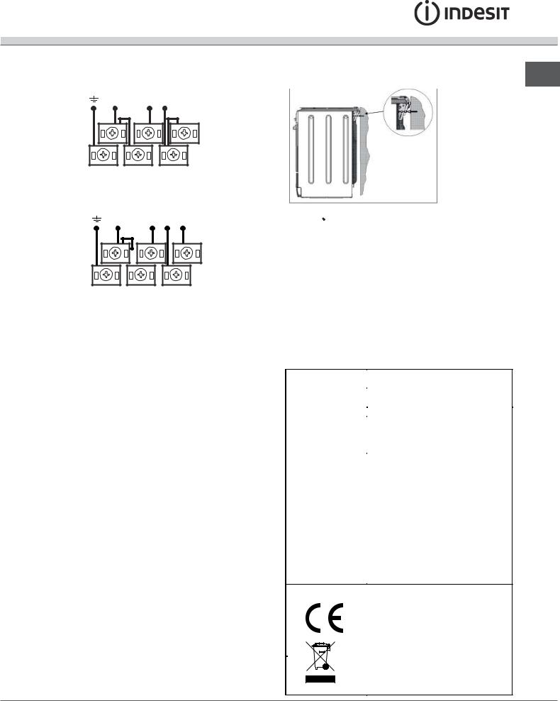
400V 2N~
H05RR-F 4x4 CEI-UNEL 35363 H05VV-F 4x4 CEI-UNEL 357 46
N |
L2 L1 |
5 |
3 |
1 |
|
4 |
2 |
400V 3N~
H05RR-F 5x2.5 CEI-UNEL 35363 H05VV-F 5x2.5 CEI-UNEL 35746
N L3 L2 L1
5 |
3 |
1 |
|
4 |
2 |
•Secure the power supply cable by fastening the cable clamp screw then put the cover back on.
Connecting the supply cable to the electricity mains
Install a standardised plug corresponding to the load indicated on the appliance data plate (see Technical data table).
The appliance must be directly connected to the mains using an omnipolar switch with a minimum contact opening of 3 mm installed between the appliance and the mains. The switch must be suitable for the charge indicated and must comply with current electrical regulations (the earthing wire must not be interrupted by the switch). The supply cable must be positioned so that it does not come into contact with temperatures higher than 50°C at any point.
Before connecting the appliance to the power supply, make sure that:
•The appliance is earthed and the plug is compliant with the law.
•The socket can withstand the maximum power of the appliance, which is indicated by the data plate.
•The voltage falls between the values indicated on the data plate.
•The socket is compatible with the plug of the appliance. If the socket is incompatible with the plug, ask an authorised technician to replace it. Do not use extension cords or multiple sockets.
! Once the appliance has been installed, the power supply cable and the electrical socket must be easily accessible.
!The cable must not be bent or compressed.
!The cable must be checked regularly and replaced
by authorised technicians only.
!The manufacturer declines any liability should these safety measures not be observed.
! In order GB
Safety Chain |
to prevent |
|
|
|
accidental |
|
tipping of the |
|
appliance, for |
|
example by |
|
a child clim- |
|
bing onto the |
|
oven door, the |
|
supplied safety |
|
chain MUST be |
|
installed! |
The cooker is fitted with a safety chain to be fixed by means of a screw (not supplied with the cooker) to the wall behind the appliance, at the same height as the chain is attached to the appliance.
Choose the screw and the screw anchor according to the type of material of the wall behind the appliance. If the head of the screw has a diameter smaller than 9mm, a washer should be used. Concrete wall requires the screw of at least 8mm of diameter, and
60mm of length.
Ensure that the chain is fixed to the rear wall of the cooker and to the wall, as shown in figure, so that
after installation it is tensioned and parallel to the ground level.
TECHNICAL DATA |
|
|
|
|
|
Oven dimensions |
40x43,5x32 cm |
|
(LxDxH) |
|
|
|
|
|
Volume |
58 l |
|
Useful |
width 42 cm |
|
measurements |
|
|
depth 44 cm |
|
|
relating to the oven |
|
|
height 8,5 cm |
|
|
compartment |
|
|
|
|
|
Power supply |
see data plate |
|
voltage and |
|
|
frequency |
|
|
|
Directive 2002/40/EC on the label of |
|
|
electric ovens. Standard EN 50304 |
|
|
Energy consumption for Natural |
|
ENERGY LABEL |
convection – heating mode: |
Static; |
|
|
|
Energy consumption for Forced
convection – heating mode: Baking Mode;
EC Directives: 06/95/EC dated 12/12/06 (Low Voltage) and subsequent amendments –
04/108/EC dated 15/12/04 (Electromagnetic Compatibility) and subsequent amendments – 93/68/EEC dated 22/07/93 and subsequent amendments – 2002/96/EC.
1275/2008 Stand-by/ Off mode
4
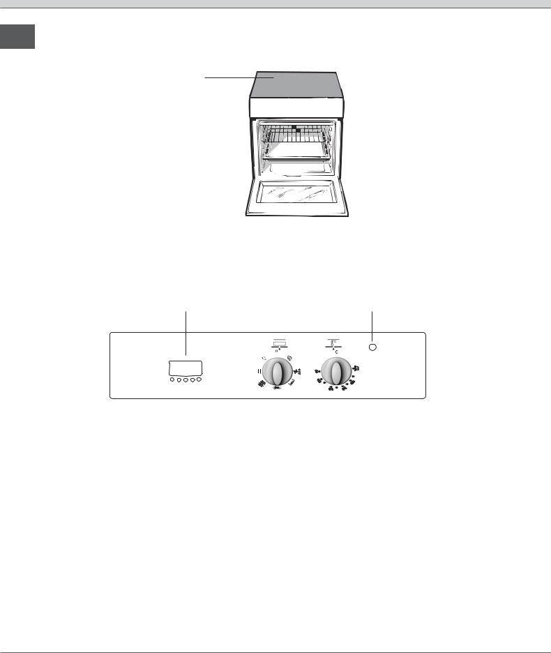
Description of the appliance
Overall view
GB
Glass ceramic hob
Control panel |
|
|
|
|
|
|
|
|
|
|
|
|
|
GUIDE RAILS |
|
|
|
|
|
|
|
|
|
|
|
||||
|
|
|
|
|
|
|
|
|
|
|
|
|
|
for the sliding racks |
RACK shelf |
|
|
|
|
|
|
|
|
|
|
|
|
position 5 |
|
|
|
|
|
|
|
|
|
|
|
|
|
|||
|
|
|
|
|
|
|
|
|
|
|
position 4 |
|||
|
|
|
|
|
|
|
|
|
|
|||||
DRIPPING PAN shelf |
|
|
|
|
|
|
|
|
|
|
|
|
position 3 |
|
|
|
|
|
|
|
|
|
|
|
|
|
|||
|
|
|
|
|
|
|
|
|
|
position 2 |
||||
|
|
|
|
|
|
|
|
|
|
|
|
|
|
|
Adjustable foot |
|
|
|
|
|
|
|
|
|
|
|
position 1 |
||
|
|
|
|
|
|
|
|
|
|
|
||||
|
|
|
|
|
|
|
|
|
Adjustable foot |
|||||
|
|
|
|
|
|
|
|
|||||||
Control panel
ELECTRONIC |
THERMOSTAT |
TIMER |
indicator light |
PROGRAMMER |
|
THERMOSTAT |
knob |
|
knob |
|
|
|
5
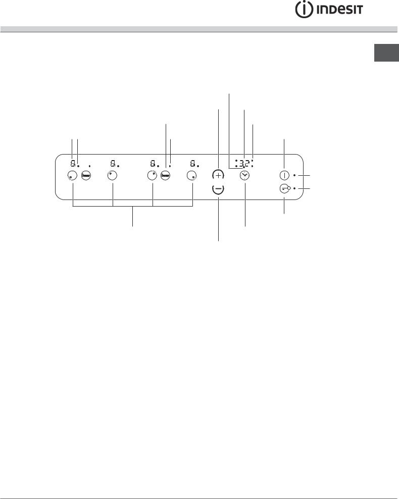
Hob control panel
GB
|
|
|
TIMER* |
|
|
|
indicator light |
|
|
INCREASE |
PROGRAMME TIMER* |
|
|
POWER button |
display |
|
|
BOOSTER* |
COOKING ZONE PROGRAMMED* |
|
|
button |
indicator light |
POWER and |
COOKING ZONE |
BOOSTER* |
ON/OFF |
|
|||
RESIDUAL HEAT |
SELECTED indicator light |
indicator light |
button |
|
|||
indicators |
|
|
|
|
b o o ste r |
b o o ste r |
ON/OFF |
|
indicator light |
||
|
|
|
|
|
|
|
CONTROLS LOCKED |
|
|
|
indicator light |
|
|
|
CONTROL PANEL |
|
|
|
LOCK button |
|
|
COOKING ZONE |
PROGRAMME |
|
|
SELECTOR buttons |
TIMER* button |
REDUCE POWER button
•INCREASE POWER button switches on the hotplate and controls the power (see Start-up and use).
•REDUCE POWER button controls the power and switches off the hotplate (see Start-up and use).
•COOKING ZONE SELECTOR button shows a particular cooking zone has been selected and therefore various adjustments are possible.
•COOKING ZONE SELECTOR button is used to select the desired cooking zone.
•POWER indicator provides a visual display for the current heat level.
•ON/OFF button switches the appliance on and off.
•ON/OFF indicator light shows whether the appliance is on or off.
•PROGRAMME TIMER* button controls the cooking programme times (see Start-up and use).
* Only available in certain models.
•PROGRAMME TIMER* display shows which programme has been selected (see Start-up and use).
•COOKING ZONE PROGRAMMED* indicator lights show which cooking zones are being used during a cooking programme (see Start-up and use).
•CONTROL PANEL LOCK button prevents accidental changes to the hob settings (see Startup and use).
•CONTROL PANEL LOCK indicator light shows the control panel has been locked (see Start-up and use).
•BOOSTER button* activates the booster function - 3000 W - of the cooking zone (see Start-up and use).
•BOOSTER indicator light* shows that the booster function has been activated.
•TIMER* indicator light shows that the timer has been activated
6
 Loading...