

Indesit I6MG1G / EX, I6GG10G /EX, I6TG1G /EX, I6TG1G.K / EX, I6TG1G GH Operating Instructions Manual
English
GB
Operating Instructions
COOKER AND OVEN
Contents
Operating Instructions,1
Description of the appliance-Overall view,2
Description of the appliance-Control Panel,3
Installation,4
Start-up and use,10
Precautions and tips,13
Care and maintenance,14
Assistance,14
FR
Français
Mode d’emploi
CUISINIERE ET FOUR
Sommaire
Mode d’emploi,1
Description de l’appareil-Vue d’ensemble, 2
Description de l’appareil-Tableau de bord, 3
Installation,16
Mise en marche et utilisation,22
Précautions et conseils, 25
Nettoyage et entretien,26
Assistance,27
Español
ES
Manual de instrucciones
COCINA Y HORNO
Sumario
Manual de instrucciones,1
Descripción del aparato-Vista de conjunto,2
Descripción del aparato-Panel de control,3
Instalación,28
Puesta en funcionamiento y uso,34
Precauciones y consejos,37
Mantenimiento y cuidados,38
Asistencia,38
PT
Português
Instruções para a utilização
FOGÃO E FORNO
Índice
Instruções para a utilização,1
Descrição do aparelho-Vista de conjunto,2
Descrição do aparelho-Painel de comandos,3
Instalaçao,40
Início e utilizaçao, 46
Precauçoes e conselhos,49
Manutençao e cuidados,50
Assistencia técnica,50
AR
ﻞﻴﻐﺸﺘﻟا تﺎﻤﻴﻠﻌﺗ
خﺎّﺒﻃ
تﺎﻳﻮﺘﺤﻤﻟا
ﻞﻴﻐﺸﺘﻟا
تﺎﻤﻴﻠﻌﺗ
1
زﺎﻬﺠﻟا
ﻒﺻو
ﺔﻣﺎﻋ ةﺮﻈﻧ
2
ﻢﻜﺤﺘﻟا ﺔﺣﻮﻟ
3
ﺐﻴﻛﺮﺘﻟا
ماﺪﺨﺘﺳﻻاو ﻞﻴﻐﺸﺘﻟا
ﺢﺋﺎﺼﻧو رﺬﺣ ﻞﺋﺎﺳو
ﺔﻧﺎﻴﺼﻟاو
ﺔﻳﺎﻨﻌﻟا
I6TG1G.K / EX
I6TG1G GH / EX
I6MG1G / EX I6GG10G /EX
I6TG1G /EX
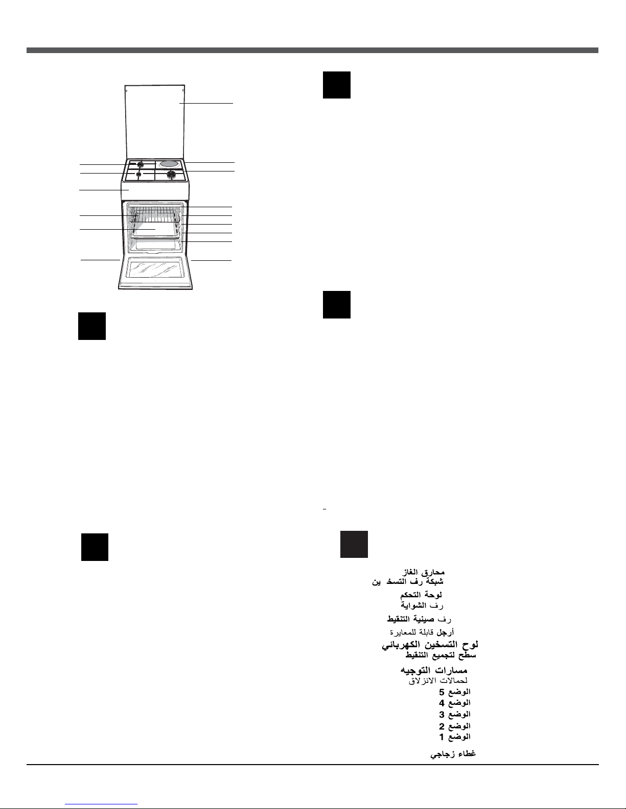
2
1.Hob burner
2.Hob Grid
3.Control panel
4.Sliding grill rack
5.DRIPPING pan
6.Adjustable foot
7.ELECTRIC HOTPLATE
8.Containment surface for spills
9.GUIDE RAILS for the sliding racks
10.position 5
11.position 4
12.position 3
13.position 2
14.position 1
15.Glass Cover *(Available only on certain models)
Description of the appliance
Overall view
GB
1.Brûleur à gaz
2.Grille du plan de cuisson
3.Tableau de bord
4.Support GRILLE
5.Support LECHEFRITE
6.Pied de réglage
7. Table de cuisson electrique
8. Plateau du plan de cuisson
9. GLISSIERES de coulissement
10. niveau 5
11. niveau 4
12. niveau 3
13. niveau 2
14. niveau 1
15.
Couvercle en verre
(N’existe que sur certains modèles)
Description de l’appareil
Vue d’ensemble
FR
1.Quemador de gas
2. Plano de contención eventuales derrames
3.Panel de mandos
4.Rejilla estante del horno
5.Asadera o plano de cocción
6.Patitas regulables
7.E
NCIMERA ELÉCTRICA
8.Rejilla del plano de cocción
9. GUÍAS de deslizamiento de las bandejas
10.
POSICIÓN
5
11.
POSICIÓN 4
12.
POSICIÓN
3
13.
POSICIÓN 2
14.
POSICIÓN 1
15.Tapa de vidrio (Presente sólo en algunos modelos)
Descripción del aparato
Vista de conjunto
ES
1.Queimador a gás
2.Grade do piano de trabalho
3.Painel de comandos
4.Prateleira GRADE
5.Prateleira BANDEJA PINGADEIRA
6. Pé de regulação
7.Plano eléctrico
8.Plano de retenção dos eventuais vazamentos
9.GUIAS de deslizamento das prateleiras
10.Posição 5
11.Posição 4
12.Posição 3
13. Posição 2
14. Posição 1
15.O sobretampo de vidro
(Presente apenas em alguns modelos)
Descrição do aparelho
Vista de conjunto
PT
1
2
3
4
5
6
7
8
9
10
11
12
13
14
15
6
زﺎﻬﺠﻟا
ﻒﺻو
ﺔﻣﺎﻋ ةﺮﻈﻧ
1.
2.
3.
4.
5.
6.
7.
8.
9.
10.
11.
12
13.
14.
15.
AR
GB
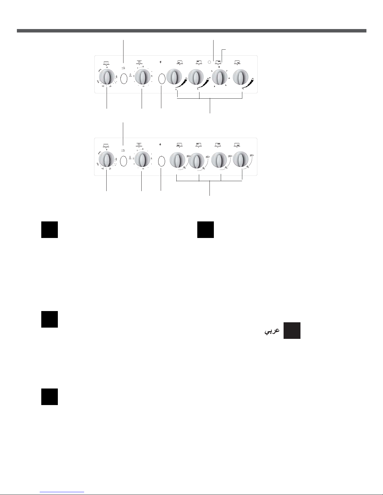
3
Description of the appliance
Control panel
GB
1.THERMOSTAT knob
2.OVEN LIGHT / ROTISSERIE button
3.TIMER knob
4.GAS BURNER IGNITION button
5. Hob BURNER control knob
6.ELECTRIC HOTPLATE indicator light
7.Electric HOTPLATE control knob
Description de l’appareil
Tableau de bord
FR
Descripción del aparato
Panel de control
ES
1.Perilla del termóstato
2.Botón de la luz del forno y asador automático
3.El contador de minutos
4.Encendido electrónico de los quemadores
5.Perillas de mando de los quemadores
6.Luz indicadora de funcionamiento de las placas eléctricas
7.Las perillas de mando de las placas eléctricas de la
encimera
1.Manette du THERMOSTAT
2.Bouton ECLAIRAGE/ TOURNEBROCHE
3.Manette du MINUTEUR
4.Allumage électronique des brûleurs du plan de cuisson
5.Manette BRULEURS
6.Voyant de fonctionnement de la plaque électrique
7.Manette de la plaque électrique
Descrição do aparelho
Painel de comandos
PT
1.Selector para a temperatura de cozedura (termostato)
2.Manípulo luz do forno
3.Manípulo conta-minutos
4.Acendedor electrónico dos queimadores do plano
5.Botão luz do forno e rotisserie
6.Indicador de funcionamento chapas
7.Botões de comando das chapas eléctricas
6
1
2
3
4
5
6*
7*
6
1
2
3
4
5
AR
ﻂﻘﻓ ﺔﻨﻴﻌﻣ تازاﺮﻃ ﻲﻓ ﺮﻓﻮﺘﻣ
*
ﻢﻜﺤﺘﻟا ﺔﺣﻮﻟ
زﺎﻏ قﺮﺤﻣ
*لﺎﻌﺷﻹا رز
ﺔﺤﻴﻔﺻ ﺮﺷﺆﻣ ءﻮﺿ
ﺔﻄﺸﻨﻟﺍ ﻦﻴﺨﺴﺘﻟﺍ
ﺔﻴﺋﺎﺑﺮﻬﻛ ﻦﻴﺨﺴﺗ ﺔﺤﻴﻔﺼﺑ ﻢﻜﺤﺗ
ﻦﻴﺨﺴﺘﻟﺍ ﺔﺤﻴﻔﺻ ﺡﺎﺘﻔﻣ
ﺔﻴﺋﺎﺑﺮﻬﻜﻟﺍ
ﺭﺎﻴﺘﺧﻻﺍ ﺡﺎﺘﻔﻣ
ﺔﻋﺎﺳ حﺎﺘﻔﻣ
ﺖﻴﻗﻮﺘﻟا
*
*
*
رز
نﺮﻔﻟا ةءﺎﺿا و يﻮﺸﻟا روﺪﻣ
*
1.
2.
3.
4.
5.
6.
4
GB
! Before operating your new appliance please read
this instruction booklet carefully. It contains important
information concerning the safe installation and
operation of the appliance.
! Please keep these operating instructions for future
reference. Make sure that the instructions are kept with
the appliance if it is sold, given away or moved.
! The appliance must be installed by a qualified
professional according to the instructions provided.
! Any necessary adjustment or maintenance must be
performed after the cooker has been disconnected
from the electricity supply.
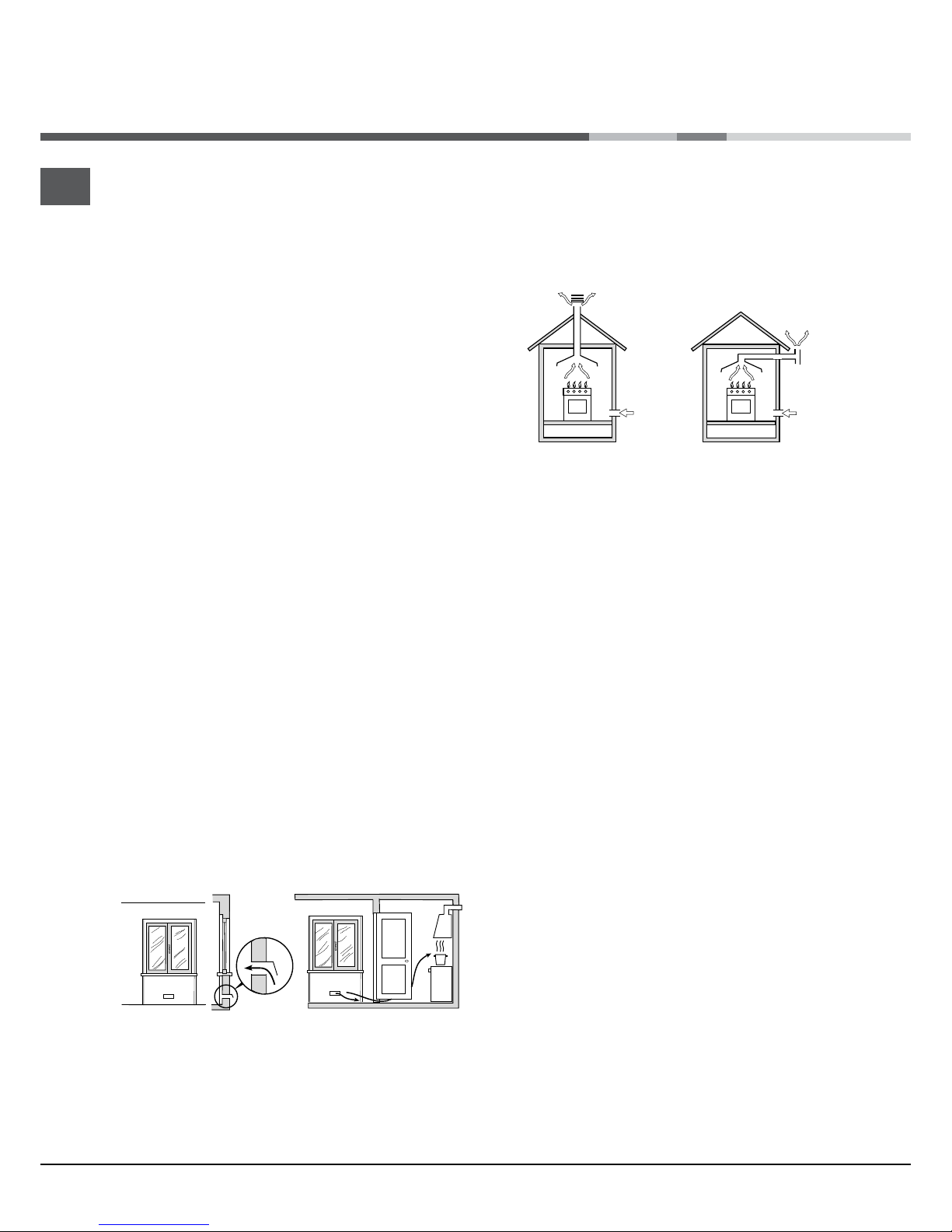
Room ventilation
The appliance may only be installed in permanentlyventilated rooms, according to current national
legislation. The room in which the appliance is installed
must be ventilated adequately so as to provide as
much air as is needed by the normal gas combustion
process (the flow of air must not be lower than 2 m
3
/h
per kW of installed power).
The air inlets, protected by grilles, should have a duct
with an inner cross section of at least 100 cm
2
and
should be positioned so that they are not liable to even
partial obstruction (see figure A).
These inlets should be enlarged by 100% - with a
minimum of 200 cm
2
- whenever the surface of the
hob is not equipped with a flame failure safety device.
When the flow of air is provided in an indirect manner
from adjacent rooms (see figure B), provided that
these are not communal parts of a building, areas with
increased fire hazards or bedrooms, the inlets should
be fitted with a ventilation duct leading outside as
described above.
Adjacent room Room
requiring
ventilation
Disposing of combustion fumes
The disposal of combustion fumes should be
guaranteed using a hood connected to a safe and
efficient natural suction chimney, or using an electric
fan that begins to operate automatically every time the
appliance is switched on (see figure).
Installation
A
A B
! After prolonged use of the appliance, it is advisable to
open a window or increase the speed of any fans used.
! The liquefied petroleum gases are heavier than air
and collect by the floor, therefore all rooms containing
LPG cylinders must have openings leading outside so
that any leaked gas can escape easily.
LPG cylinders, therefore, whether partially or
completely full, must not be installed or stored in rooms
or storage areas that are below ground level (cellars,
etc.). Only the cylinder being used should be stored
in the room; this should also be kept well away from
sources of heat (ovens, chimneys, stoves) that may
cause the temperature of the cylinder to rise above
50°C.
Positioning and levelling
! It is possible to install the appliance alongside
cupboards whose height does not exceed that of the
hob surface.
! Make sure that the wall in contact with the back of
the appliance is made from a non-flammable, heatresistant material (T 90°C).
To install the appliance correctly:
• Place it in the kitchen, dining room or the bed-sit (not
in the bathroom).
• If the top of the hob is higher than the cupboards,
the appliance must be installed at least 600 mm away
from them.
• If the cooker is installed underneath a wall cabinet,
there must be a minimum distance of 420 mm
between this cabinet and the top of the hob.
This distance should be increased to 700 mm if the
wall cabinets are flammable (see figure).
Ventilation opening
for comburent air
Increase in the gap
between the door and
the flooring
Fumes channelled
straight outside
Fumes channelled through
a chimney or a branched
flue system (reserved for
cooking appliances)
GB
5
• Do not position
blinds behind the cooker or less than 200 mm away
from its sides.
• Any hoods must be installed according to the
instructions listed in the relevant operating manual.
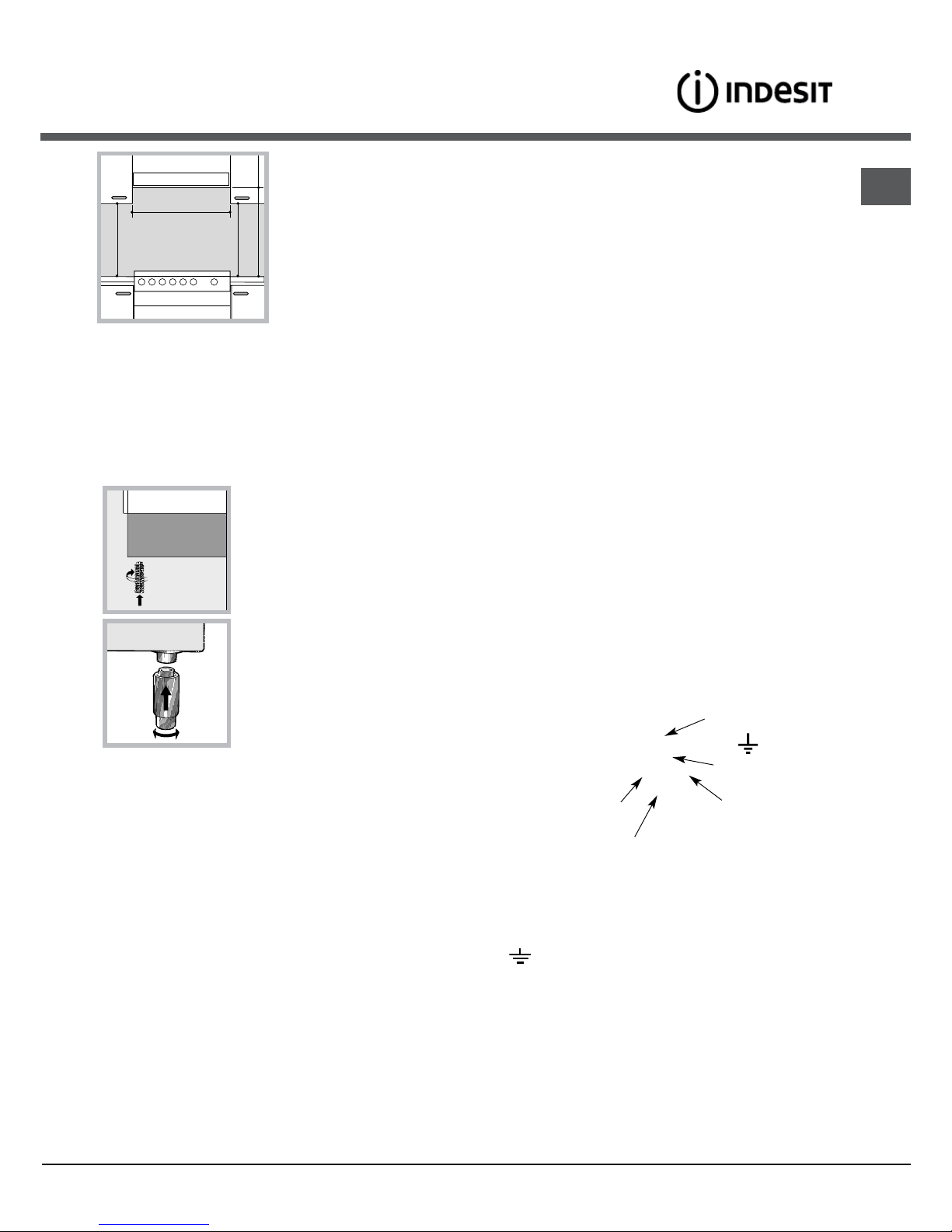
Levelling
If it is necessary to level the
appliance, screw the adjustable
feet into the places provided on
each corner of the base of the
cooker (see figure).
The legs* fit into the slots on the
underside of the base of the
cooker.
Electrical connection
Install a standardised plug corresponding to the load
indicated on the appliance data plate (see Technical
data table).
The appliance must be directly connected to the mains
using an omnipolar circuit-breaker with a minimum contact
opening of 3 mm installed between the appliance and the
mains. The circuit-breaker must be suitable for the charge
indicated and must comply with current national legislation
(the earthing wire must not be interrupted by the circuitbreaker). The supply cable must be positioned so that it
does not come into contact with temperatures higher than
50°C at any point.
Before connecting the appliance to the power supply,
make sure that:
• The appliance is earthed and the plug is compliant with
the law.
• The socket can withstand the maximum power of the
appliance, which is indicated by the data plate.
• The voltage is in the range between the values
indicated on the data plate.
• The socket is compatible with the plug of the
appliance. If the socket is incompatible with the
plug, ask an authorised technician to replace it. Do
not use extension cords or multiple sockets.
! Once the appliance has been installed, the power
supply cable and the electrical socket must be easily
accessible.
! The cable must not be bent or compressed.
! The cable must be checked regularly and replaced
by authorised technicians only.
! The manufacturer declines any liability should
these safety measures not be observed.
HOOD
420
Min.
min.
650
mm. with hood
min.
700
mm. without hood
mm.
600
Min. mm.
420
Min. mm.
* Only available in certain models
IF THE FITTED PLUG IS REMOVED*
The exible mains lead must be correctly connected as
below to a three pin plug of not less than 13 amp capacity.
If a B.S. 1363 fused plug is used, it must be tted with a
fuse which is approved to B.S. 1362.
Important: the wires in the mains lead are coloured in
accordance with the following code:
Green & Yellow - Earth
Blue - Neutral
Brown - Live
The power supply cable must be type H05VV-F
Green &
Yellow to
Earth
Brown
to Live
Blue to
Neutral
Cord
Clamp
3 Amp
Fuse
As the colours of the wires in the mains lead may not
correspond with the coloured markings identifying the
terminals in your plug, proceed as follows:
Connect the Green & Yellow wire to terminal marked “E”
or
or coloured Green or Green & Yellow.
Connect the Brown wire to the terminal marked “L” or
coloured Red.
Connect the Blue wire to the terminal marked “N” or
coloured Black.
FAILURE TO OBSERVE THE ACCIDENT-PREVENTION
REGULATIONS RELIEVES THE MANUFACTURER OF
ALL LIABILITY.
 Loading...